Abstract
Low geometric accuracy is one of the main limitations in double-sided incremental forming (DSIF) with a rough surface finish, long forming time, and excessive sheet thinning. The lost contact between the support tool and the sheet is considered the main reason for the geometric error. Researchers presented different solutions for geometric accuracy improvement, such as toolpath compensation, adaptation, material redistribution, and heat-assisted processes. Toolpath compensations strategies improve geometric precision without adding extra tooling to the setup. It relies on formulas, simulation, and algorithm-based studies to enhance the part accuracy. Toolpath adaptation improves the part accuracy by adding additional equipment such as pneumatically or spring-loaded support tools or changing the conventional toolpath sequence such as accumulative-DSIF (ADSIF) and its variants. It also includes forming multi-region parts with various arrangements. Toolpath adaptation mostly requires experimental trial-and-error experiments to adjust parameters to obtain the desired shape with precision. Material redistribution strategies are effective for high-wall-angle parts. It is the less studied area in the geometric precision context in the DSIF. The heat-assisted process mainly concentrates on hard-to-form material. It can align itself to any toolpath compensation or adaptation strategy. This work aims to provide DSIF variants and studies, which focus on improving geometric accuracy using various methodologies. It includes a brief survey of tool force requirements for different strategies, sheet thickness variation in DSIF, and support tool role on deformation and fracture mechanism. Finally, a brief discussion and future work are suggested based on the insights from several articles.
1. Introduction
Ideas need to be converted quickly into products and analyzed to meet the requirements of the industrial revolution. Manufacturing processes having less changeover time and tooling cost can fulfill the prerequisite of mass customization and prototype development. The prototype allows improvement in the design in the early stages of product development. Conventional manufacturing processes require a long time and capital for small batch production and prototype development. Forming operations require component-specific and expensive dies as their design and preparation are time-consuming. In recent years, incremental sheet forming (ISF) has gained significant attraction due to its capability for prototype and small-batch productions with short lead time and generic tooling. In ISF, flat metal sheets are incrementally deformed into complex three-dimensional components using a computer numerically controlled (CNC) generic tool. During the forming, the sheet is peripherally clamped. Higher formability, less forming forces, high geometric flexibility, less lead time, low cost for production of customized and low-volume components than stamping and deep drawing are the salient features of ISF. Furthermore, a wide range of materials can be formed such as steel, aluminum, copper, polymers, titanium, etc. It has considerable potential in the aerospace industry, prototyping in automotive, on-site repair for military applications, personalized products in the medical, architecture, etc. [1,2].
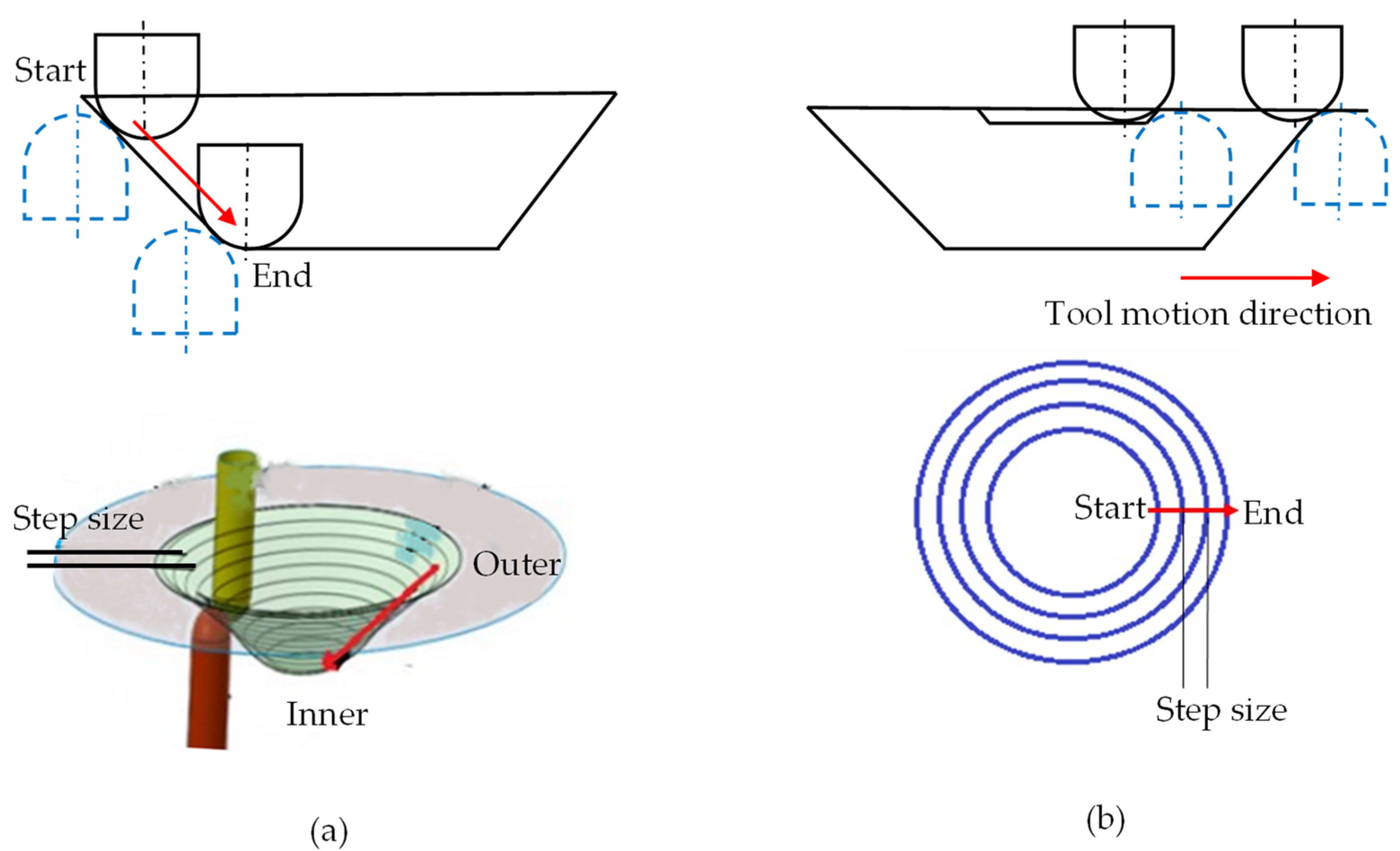
Existing experimental configurations for ISF can broadly be classified into three categories: single-point incremental forming (SPIF), two-point incremental forming (TPIF), and DSIF. In SPIF, a material sheet is clamped peripherally and deformed locally using a small hemispherical-ended tool moving along a predefined toolpath on one side. The local deformations accumulate to impart a required shape to the sheet (Figure 1a). The part accuracy in SPIF is low due to unavoidable and unintended bending of the sheet. The attempts to improve the part accuracy by processing it independently in different regions were unsuccessful. A closed-loop strategy based on spatial impulse responses and partially cut out blank to avoid global deformation was also unable to improve the SPIF accuracy [3,4]. Nasulea and Oancea utilized a circumferential hammering forming tool for improving geometric precision [5]. Different researchers have also evaluated other parameters such as tool size, step size, lubricant type, forming speeds, sheet thickness estimation on formability, sheet thickness, and geometric precision [2,6,7,8,9]. Various options were proposed and trialed; however, part accuracy did not significantly improve in SPIF.

Figure 1.
Schematics of ISF Processes (a) SPIF (b) TPIF (c) DSIF.
In TPIF, an extra full or partial die is used on the other side of the sheet to enhance the part accuracy (Figure 1b) [7]. Tool diameter, step size, and other parameters for geometric accuracy improvement in TPIF were studied. Improvement in geometric accuracy was reported; however, process flexibility is compromised [4,10]. These limitations in SPIF and TPIF lead to the development of DSIF, which enhances part accuracy while maintaining flexibility. In the DSIF process, a second support tool is used on the opposite side of the sheet, acting as local support for the master (forming) tool (Figure 1c). The CAD/CAM software usually gives the master tool coordinates. The coordinates of the support tool are determined relative to the master tool position. The process sequence is almost similar to the SPIF process except for an additional support tooling and synchronized movement with the master tool (Figure 1c).
Many in-depth reviews on the ISF have been published in recent years. Park and Kim [11] studied the formability improvement by the ISF process. Jeswiet et al. [2] presented a study on the advantages, disadvantages, different variants of the ISF process, formability, and tools used in the ISF process. Reddy et al. [12] presented an overview on SPIF, TPIF, and DSIF effects on accuracy, formability, and surface finish improvements. Behera et al. [13] discussed the progress in the SPIF from 2005–2015 and covered almost all the aspects of SPIF. Li et al. [14] presented a study on deformation mechanism, modeling techniques, forming force prediction, and process investigations. Duflou et al. [1] reported process fundamentals, process window enhancement, toolpath strategies, and simulation work performed in the SPIF process in detail. Ai and Long [15] studied the deformation and fracture mechanics of the ISF process. Lu et al. [16] reviewed the work performed on the geometric accuracy in the ISF field. Peng et al. [17] published the review mainly focusing on the DSIF deformation, fracture mechanisms, and formability improvement. Gohil and Modi presented a detailed review of the effect of process parameters on performance measures such as geometric precision, forming time, surface finish, material yield, and formability, etc., in the ISF process [18]. Tomasz et al. studied the SPIF process with a particular interest in the impact of process conditions on the surface finish and formability limit for lightweight materials [19]. A detailed study into these review papers reveals that the main focus was the SPIF process. Some articles presented a brief comparison of the SPIF and DSIF processes briefly.
The current study examines the geometric accuracy enhancement with DSIF toolpath strategies. In addition, material specifications, component profiles, cause-and-effect analyses, and force requirements for different techniques are discussed in detail. Before examining different toolpath strategies for geometric precision enhancement, the DSIF toolpath generating procedure, sheet thickness distribution, deformation, and fracture mechanism for the DSIF variant, are briefly discussed to understand the process fundamentals better. Finally, discussion and suggestions for improving geometric precision are presented.
2. Process Mechanism of DSIF
2.1. Toolpath Generation for DSIF Process
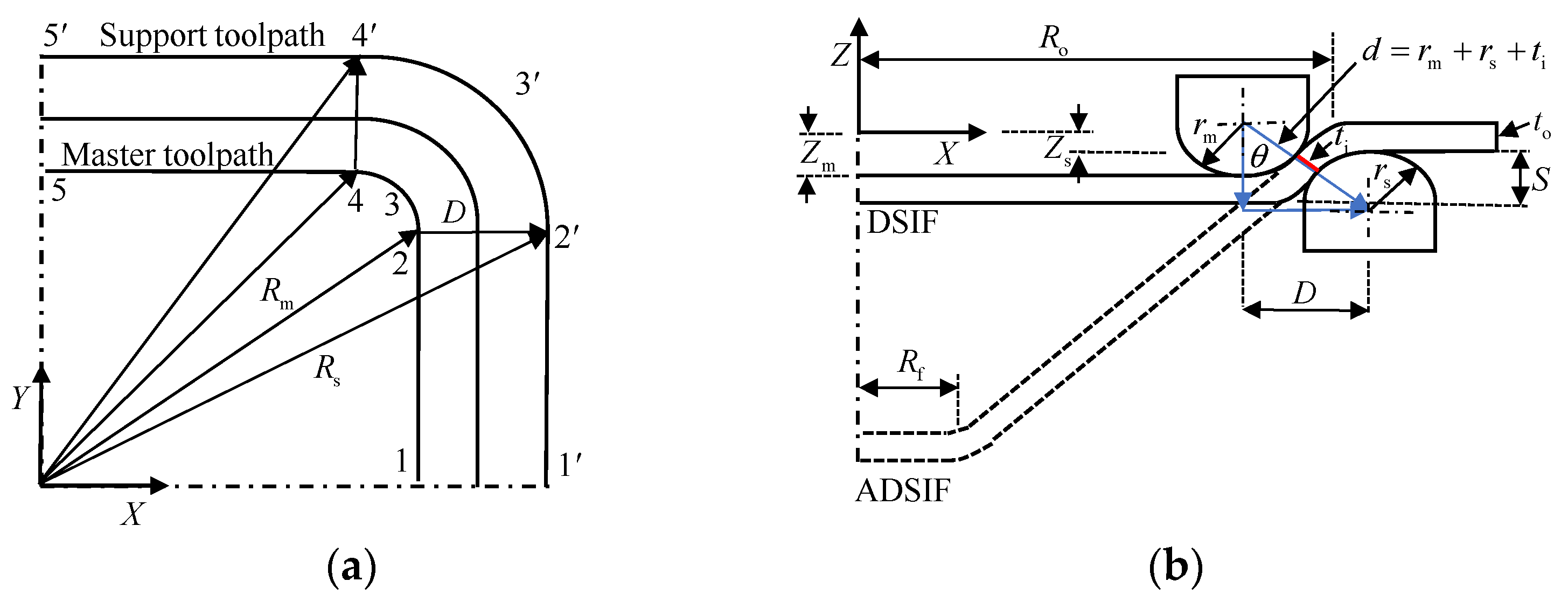
The toolpath strategy categorizes DSIF into conventional-DSIF (DSIF) and accumulative-DSIF (ADSIF). In ADSIF (Figure 2b), both tools move horizontally outward to form the components. The already processed inner material moves downward by rigid body motion [20,21]. In DSIF, the tools’ downward movement from the outer toward the inner annulus obtains the required profile. The part profile is obtained from the synchronized movement of tools via in-plane and normal to the in-plane direction such as in the SPIF process (Figure 2a).
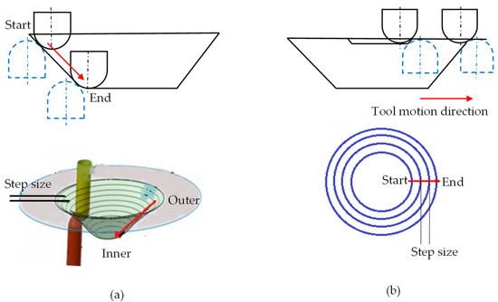
Figure 2.
Schematics of (a) DISF (b) ADSIF toolpath.
Both for DSIF and ADSIF, the master tool coordinates (, and ) are obtained from the CAD/CAM software. The position of the support tool in DSIF and ADSIF was defined via two parameters and (Figure 3) by utilizing Equations (1) and (2).
where, is the distance between the axis of the two tools in the XY plane; is the vertical distance between the bottom of the sheet and the tip of the support tool in the XZ plane; and are the master and support tool position in the XZ plane; and is the master and support tool position in the XY plane. In DSIF, parameters and are determined by utilizing the sine law and the normal tool configuration. From Figure 3b, it is evident that , and , where and is the master and support tool radius, is the local wall angle, and is original sheet thickness. The and should change continuously as part height increases due to the dependence on the sheet thickness at the contact point () (Figure 3b). Due to sine law limitations, they are mostly held constant after the initial setup at the first contour.
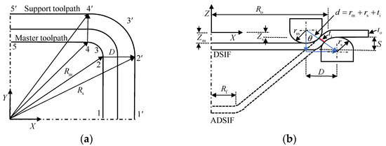
Figure 3.
DSIF and ADSIF toolpath generation strategy (reprinted with permission from S. Ullah et al. [22]). (a) top view (b) side view.
In DSIF, a flexible support tool is used, which can change its position regarding the master tool. Based on this flexibility, many tool configurations are derived. The two tool configurations based on local support to the master tools are: aligned (DSIF-A) and normal (DSIF-LN) (Figure 4a). In DSIF-A, the tool axes are parallel and on the same line. In the DSIF-LN configuration, the tool-tip centers are along the local normal at the contact point of the sheet [23]. Due to the support tool’s ineffective utilization at the component opening, the DSIF-A configuration is not frequently used. Therefore, in this work, DSIF-L will refer to DSIF-LN unless otherwise specified. Two other tool configurations based on the support tool locations are DSIF-L and DSIF-P (Figure 4a,b). In DSIF-P, the support tool moves at the part opening to act as a backing plate. It does not take part in the actual forming operation [24]. The support tool coordinates remain fixed at the initial contour, whereas the master tool coordinates are according to the part profile. In ADSIF, Equations (1) and (2) can acquire the support tool coordinates. However, in most cases in the previous studies, the support tool position is determined based on adjusting the parameters and values iteratively with respect to the master tool (Figure 4c) [21,25].

Figure 4.
(a) Schematics of normal and aligned tool configurations in DSIF-L (b) DSIF-P (c) ADSIF.
Due to DSIF process flexibility, new toolpaths such as mixed-DSIF (MDSIF), multi-stage DSIF, and hybrid DSIF were derived. MDSIF is the combination of ADSIF and DSIF. In multi-stage, the components are formed in several stages. Hybrid DSIF (where the heat source is also incorporated) executed for geometric accuracy and formability improvement. In a nutshell, the flexible DSIF process can use different toolpath strategies to form components.
2.2. The Role of Thickness Variations in DSIF Toolpath
In ISF, the final sheet thickness is usually calculated by sine law, () where : the final sheet thickness after deformation, : the original sheet thickness, and : local wall angle. The local wall angle can be used to find the thickness at any point in the component of complex geometry. The (instant sheet thickness) in Figure 3b is not necessarily the sheet thickness predicted by sine law. This difference in from the sheet thickness indicated by sine law at different forming heights affects the support tool–sheet contacts. It is due to differences in calculated and actual and values. Malhotra et al. [26] initially reported this shortcoming in the sine law while forming the 65° cone. Sine law was used to regulate the gap between the tools. After a certain forming height, the support tool disengaged from the sheet. The process degenerated to SPIF, resulting in early fracture. Squeezing was utilized to improve the support tool–sheet contact; however, it did not ensure accuracy.
According to Moser et al. [27], successfully maintaining contact between tools and the sheet can improve sheet thickness distribution, increase material formability, and reduce early fracture. In their view, factors responsible for the tool–sheet contact lost problem were an inaccurate prediction of thickness predicted by sine law, tool misalignment, and ignoring machine compliance effect. They concentrated on sheet thickness problems in their work and the spring back and machine compliance for the shamrock section with a 65° wall angle. Preliminary work in LS-DYNA determined the thickness profile. The D and S adjustments were according to the projected thickness of the sheet. The sheet thickness distribution was decoupled from wall angle and was associated with in-plane curvature and part height. The gap determined by sine law leads to disengagement of support tools, whereas the new approach works effectively. However, their work was specific to the shamrock part. For 90° wall angle, the sheet thickness becomes zero according to the sine law. Moser et al. [28] modified the sine law for the vertical wall angle component to prevent the tool gap from approaching zero.
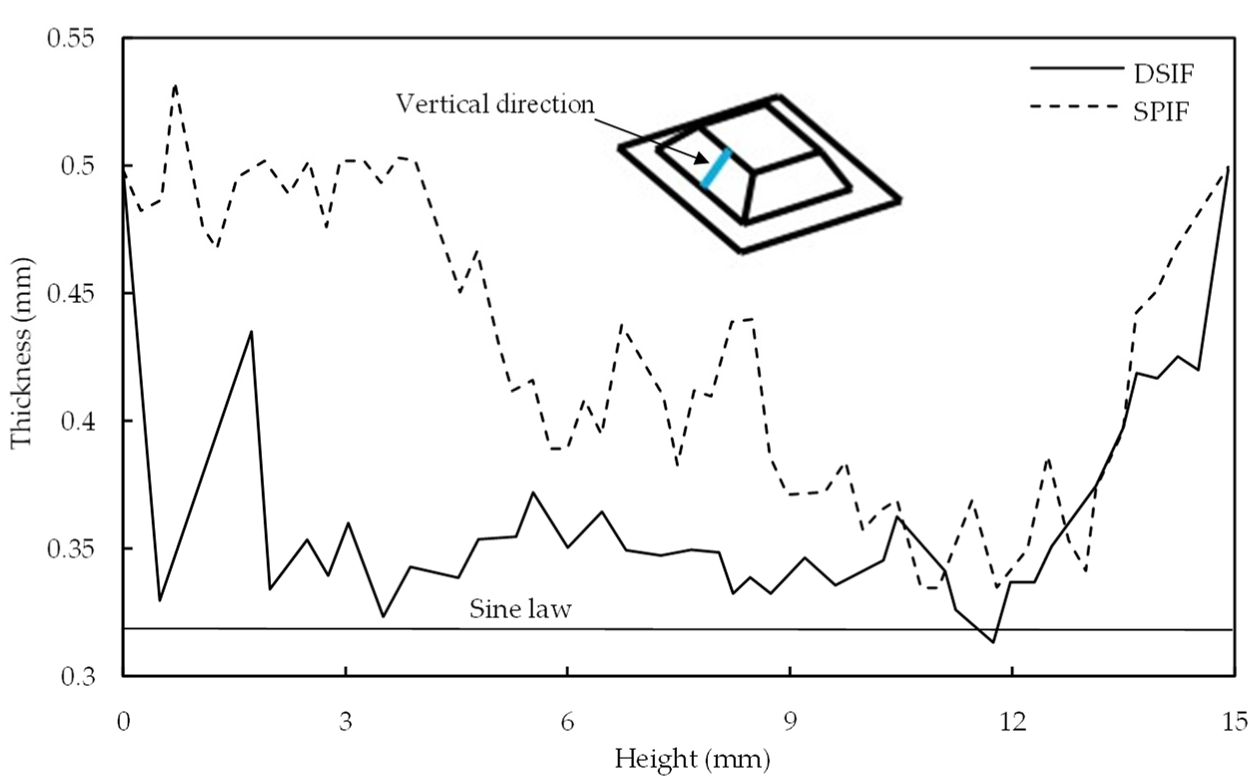
Otsu et al. [29] compared the sheet thickness distribution for SPIF and DSIF-L. SPIF does not observe the sheet thickness variation at the part opening due to global bending effects. In DSIF, the variation in sheet thickness is started from the beginning (Figure 5). It was attributed to the strong restraint on the sheet by the tools from both sides. The wall thickness predicted by sine law was 0.32 mm. As evident from Figure 5, the thickness acquired with DSIF-L is relatively closer to the sine law prediction along the complete section; however, it does not match the thickness predicted by the sine law.
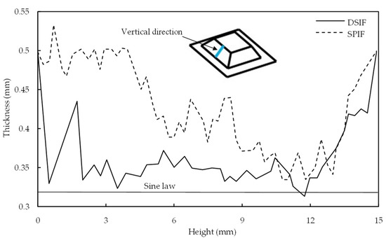
Figure 5.
Distributions of sheet thickness in the vertical direction (reprinted with permission from Otsu et al. [29], Copyright 2018 Elsevier).
Bin Lu et al. [30] compared the DSIF-L and DSIF-P strategies for wall thickness variation in a 0.5 mm sheet. No significant difference was observed in the sheet thickness acquired with DSIF-P (0.463 mm) and DSIF-L (0.461 mm). The slight difference for the DSIF-L, being on the lower side, was attributed to the local squeezing of the sheet. Malhotra et al. [31] compared the ADSIF and SPIF and observed that the sheet thickness acquired with ADSIF was on the lower side. The sheet thickness variation is minimum across the complete part height compared to SPIF. Zhang et al. [32] compared the sheet thickness variation in DSIF-L, ADSIF, and MDSIF. The thickness profile of the DSIF-L deviates relatively more from the sine law prediction, whereas the ADSIF and MDSIF processes were reported to be closer to the sine law curve.
The sheet thickness variation is the main study in SPIF [33,34,35,36]. In DSIF, the sheet thickness variation is relatively better than SPIF; however, the unpredicted thickness variation leads to ineffective tool–sheet contact, which degenerates the process to SPIF. Formability, deformation be improved by avoiding support tool–sheet lost contact.
2.3. Deformation and Fracture Mechanism in DSIF
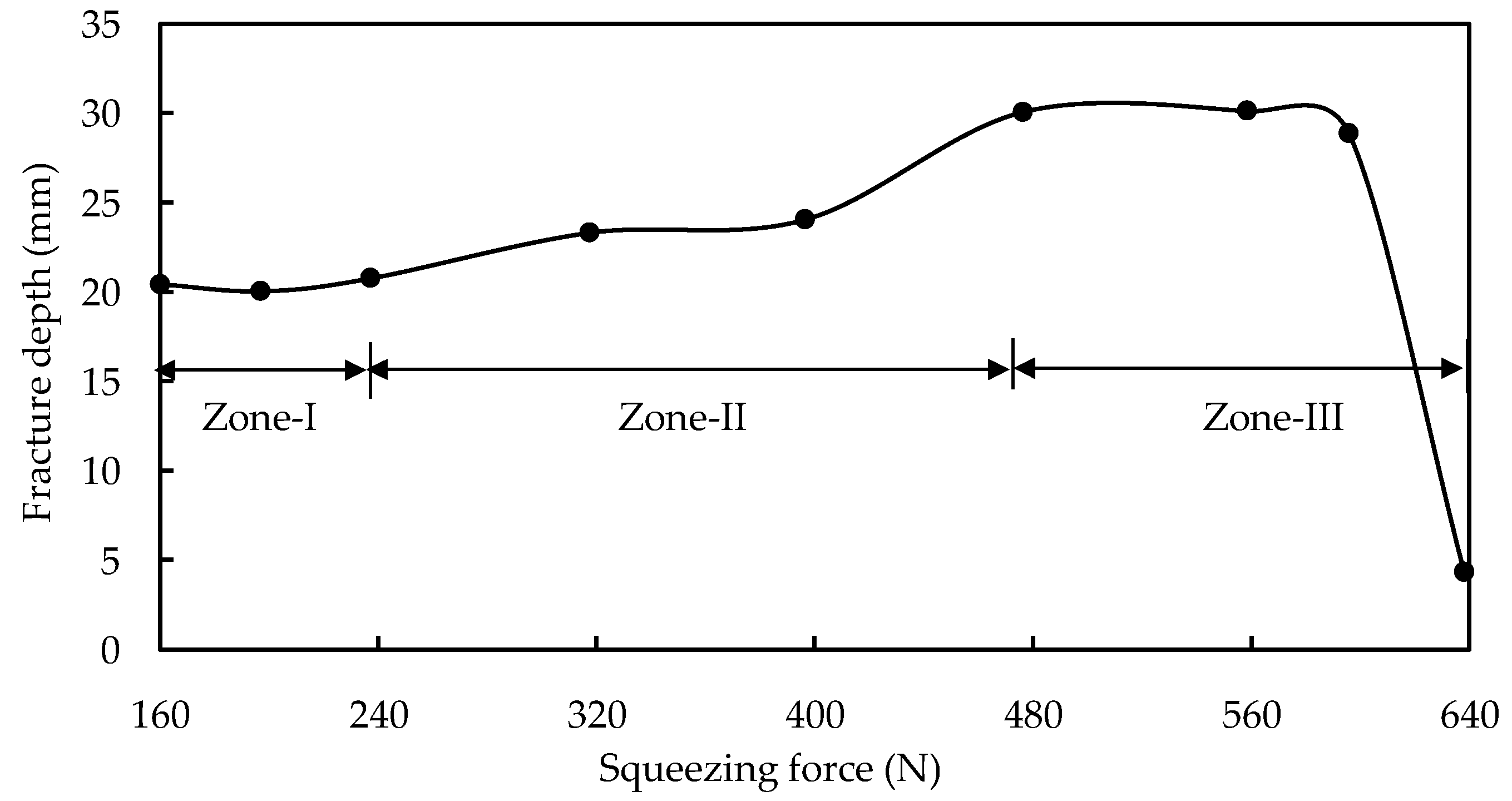
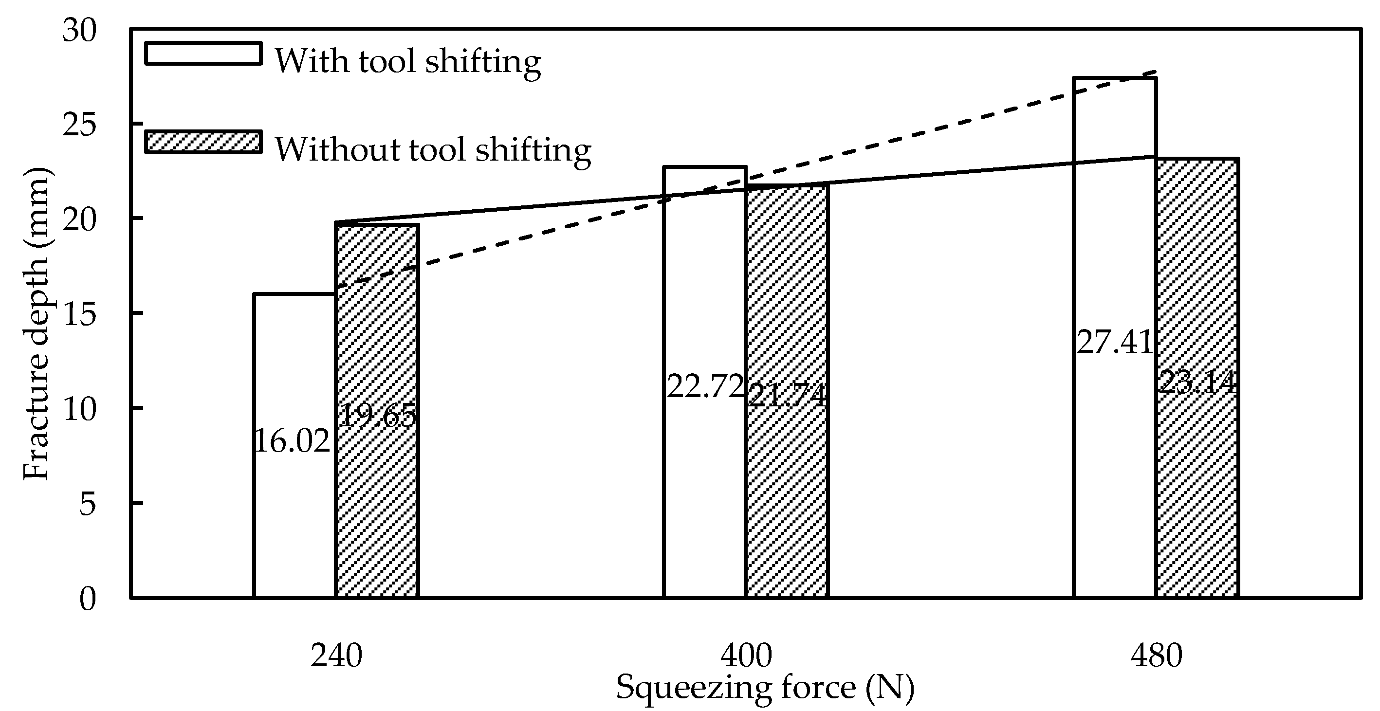
Because of the increased compressive force provided by the support tool, it is usually assumed that the DSIF has higher formability than the SPIF. The support tool must maintain constant contact with the sheet to benefit from the compressive force. Meier et al. [37] utilized the support tool with 300 N force in the DSIF-L orientation to ensure the support tool–sheet contact and reported a wall angle of 72° for the hyperboloid component. An earlier study in SPIF could not acquire a wall angle of more than 65°. The support tool force helped in increasing the formability by 12.5%. According to Malhotra et al. [26], the DSIF toolpath improves precision and formability by stabilizing distortion within a narrow zone surrounding the tool’s contact site. B. Lu et al. [38] observed the evolution of fracture depth in AA7075-T6 with varying squeezing force. For squeezing force less than 240 N, there is no significant change in the fracture depth, and the tool squeezing does not make any apparent effect. Squeezing force from 240 to 480 N increases the formability from 20 to 30 mm. Increasing the squeezing force to 560 N harms the fracture depth (Figure 6). It was analytically proved by a sudden drop in stress triaxiality point for stresses in the 240–480 N range. As illustrated in Figure 7, the forces in this range were observed for various support tool adjustments (without tool shifting is DSIF-L orientation, whereas with tool shift is support tool adjustment in the middle position between DSIF-L and DSIF-A). The increasing squeezing force with tool shift adjustments positively impacts formability improvement than the other tool adjustments. The fracture occurred in both cases in the sheet region, which was in contact with a master tool, emphasizing the relevance of the support tool in delaying the fracture. Under excessive-high contact pressure and high friction, the tools may “clamp” and “stretch” the sheet in the moving direction, leading to high tensile stress conditions around the deformation zone and early failure of the sheet.
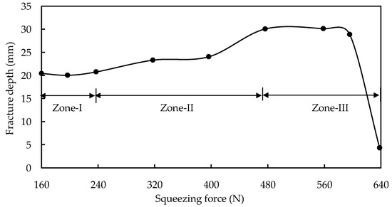
Figure 6.
Variation for forming depth under different supporting forces (reprinted with permission from B. Lu et al. [38], Copyright 2015 Elsevier).
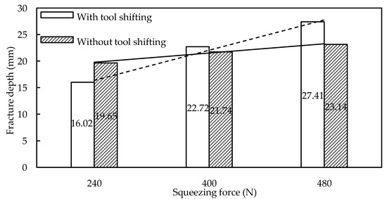
Figure 7.
Influence of slave tool shift on DSIF formability (reprinted with permission from B. Lu et al. [38], Copyright 2015 Elsevier).
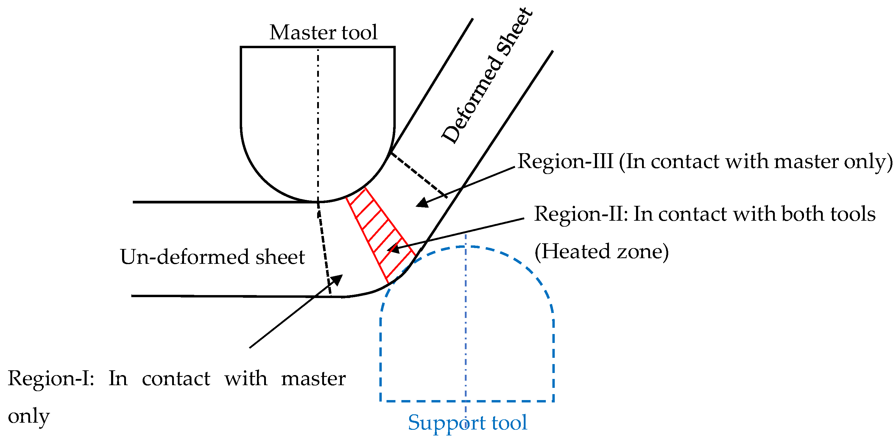
Valoppi et al. [39] utilized the analytical model proposed by B. Lu et al. [38] to investigate the fracture characteristics of Ti6Al4V sheets in the electric-assisted DSIF (E-DSIF) process. The deformation region was divided into three zones (Region-I, II, and III) to investigate the relationship between the E-DSIF fracture surfaces and the stress state (Figure 8). Region-I and III experience meridional tensile stresses, and Region-II experience compressive stresses due to support tool squeezing. They reported that the outer Region-III is more susceptible to fracture due to reduced radial thickness, local bending, more circumferential stress due to tool movement in that direction. It was further exaggerated by current, which increased through the thickness-shear too.
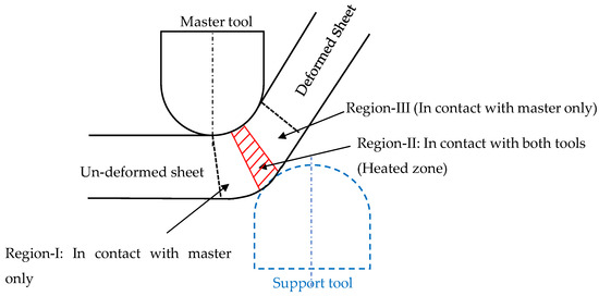
Figure 8.
Deformation zones in the E-DSIF process.
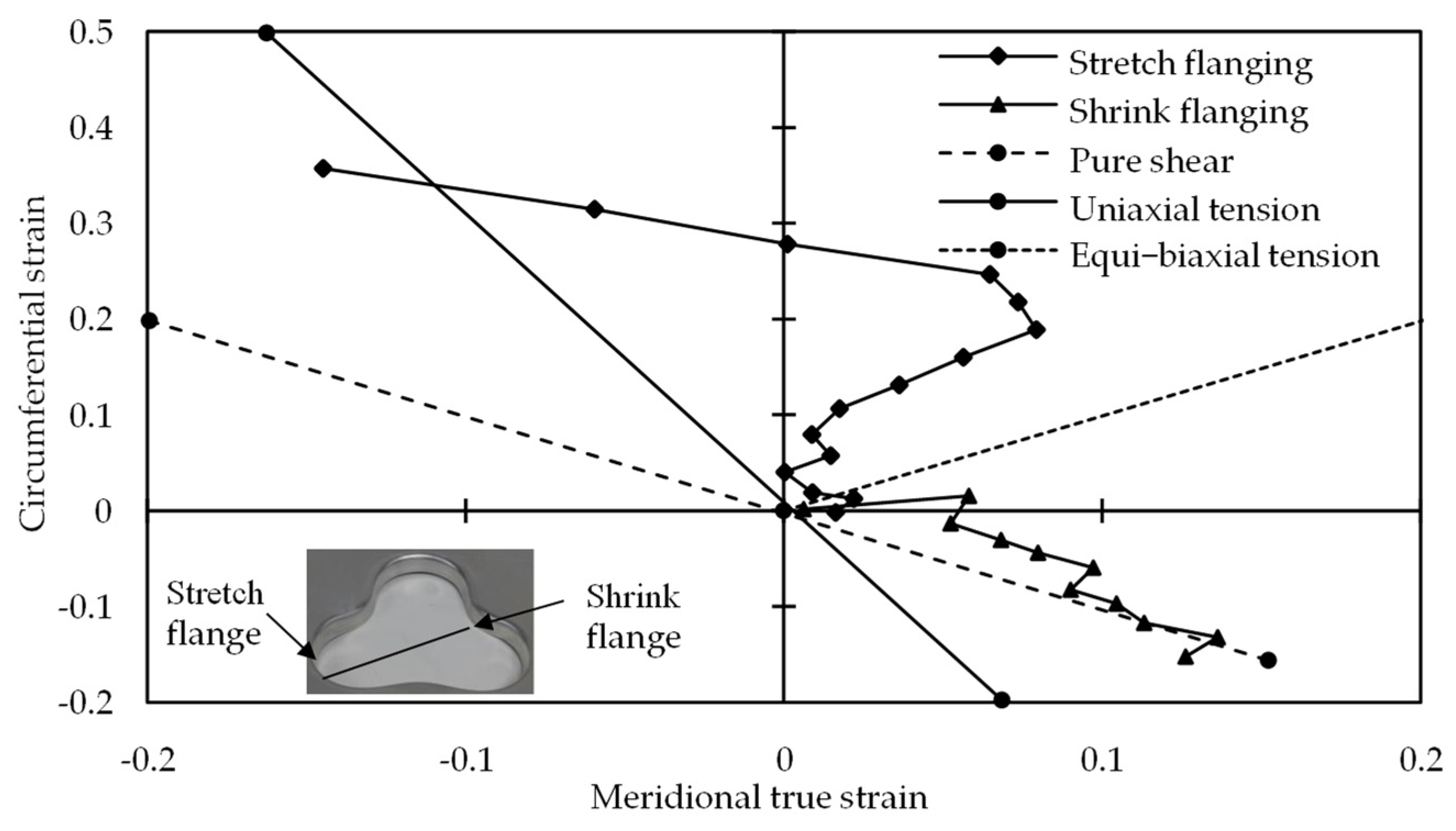
Zhang et al. [40] analyzed the strain evolution for clover flange (Figure 9). Increased circumferential and reduced meridional strain improved formability in stretch flanging. Meridional tensile and the localized deformation mode improved the formability of shrink flanging. With meridional tensile and circumferential compressive, the risk of wrinkling is minimized. With this combination, the strain state was close to pure shear, which was stable for sheet metal forming. Moser et al. [41] investigated the shrink and a stretch portion of the shamrock part. The shrink portion experience a mixture of negative strain (compressive force) and stretching. It resulted in an enlarged contact region of the support tool with the sheet, which helped effective tool–sheet contact. The support tool–sheet contact was not intact in the stretch flange as the formed height increased. It leads to a loss in squeezing, and the process becomes degenerated to SPIF having less geometric precision and formability.
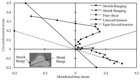
Figure 9.
Strain evolutions on X-axis cross-section (reprinted with permission from Zhang et al. [40], Copyright 2018 Elsevier).
In ADSIF, local bending of the sheet around the tool, a squeezing action due to the support tool, and shear perpendicular to and parallel to the tool motion improved formability [20]. Malhotra et al. [42] have shown that raising hydrostatic pressure and increasing through-the-thickness shear reduces the potential for sheet metal to fracture during the forming process. The higher hydrostatic pressure in ADSIF due to the support tool’s effective contact with the sheet prevents shear bands from forming. If shear bands do form, the compressive load state stops voids from expanding further, preventing material fracture. Davarpanah et al. [43] hypothesized that the support tool’s continuous contact with the sheet improved formability.
In a nutshell, the successful contact of the support tool with the sheet increases the formability and delays the fracture, as evident in the previous studies. The unpredicted thickness variation during the DSIF process, on the other hand, leads to incorrect tool gap adjustment, which in most cases degenerates the DSIF to SPIF and early fracture. It has relation to component geometric precision and is examined in the next section.
3. Accuracy Improvement in DSIF Process
This section presents the geometric error in the part’s various locations generated during the ISF process. Then, the ISF benchmarks shapes are summarized. Finally, the researcher’s toolpath strategies for improving geometric precision are presented.
The required and form profile difference is considered a geometric error [44]. In most cases, the required geometric accuracy for commercial parts is ±1 mm. In some cases, it becomes much stricter up to ±0.2 mm. The reported accuracy in ISF is still struggling to achieve these values [16]. There are mainly three regions where a geometric error occurs in the form part: (a) sheet bending between the sheet support at the periphery and current tool position (b) in-accuracy at the wall region: The error source in this region is due to (i) tool and machine compliance (ii) in-process springback (iii) post-springback after part un-clamping from the fixture. These errors are considered a challenge, and researchers have utilized different techniques to overcome the root cause for these errors (c). The unwanted curvature at the final product base (the pillow effect) is seen below (Figure 10).

Figure 10.
(a) Geometric error (reprinted with permission from Micari et al. [44], Copyright 2007 Elsevier). (b) Wall region error detail.
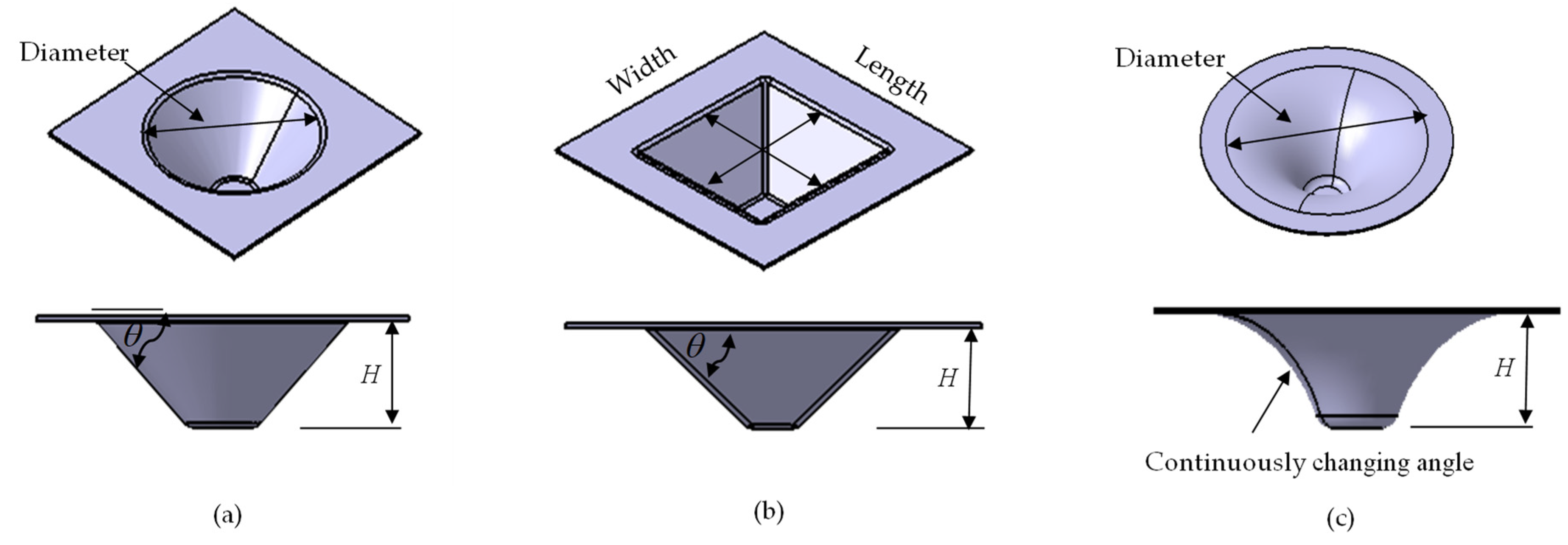
Cone, pyramid, and funnel are some of the benchmark shapes trialed by researchers in ISF (Figure 11). Besides, based on the specific challenge, some researchers have worked on other profiles such as fish fin, shamrock, ellipsoidal, etc. For pyramid, length and width at the part opening are the same unless otherwise specified. Therefore, in (Table 1, Table 2 and Table 3), in the part size column, O is used to represent both the length and width of the pyramid, whereas, for cone and funnel, it is the diameter. In the funnel, the wall angle changes continuously. It is minimum at the part opening and increases along with the part height. The part errors in this study, in most cases, represent the under-forming part. Errors defined with the plus-minus sign are for over and under-forming parts.
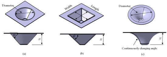
Figure 11.
ISF benchmark shape (a) cone (b) pyramid (c) funnel.

Table 1.
Accuracy improvements based on tool-path compensation.

Table 2.
Accuracy improvements based on tool-path adaptation.

Table 3.
Accuracy improvement based on the heat-assisted process.
The main focus of the early research was to validate the process’s capability to form complex parts. A robot having a 15 kg payload capacity was utilized by Meier et al. [24] to form a cone from the AA 99.5 sheet. The formed part in some regions was undersized due to material springback and oversized at others due to the machine compliance. The part accuracy became homogeneous with the heavy-duty (360 kg payload capacity) robot, as the machine compliances was reduced. Wang et al. [45] formed a complex part having curvature on both sides of the sheet without changing the setup. The machine used was a milling machine. SPIF and DSIF processes were compared for geometric accuracy by forming a sphere on the same blank. DSIF enhanced the accuracy at the part lower region, whereas SPIF performed better at the part opening area than DSIF. The reason was that a sphere was formed first with DSIF, which increased the sheet stiffness. SPIF took advantage of this increase in sheet stiffness for precision improvement at the component opening. Due to the C-frame structure utilized in their work, they were able to form parts with the wall angles in a certain range. While studying the effect of the tool gap for formability enhancement, Wang et al. [46] recommended 0.8–0.9 times the thickness of the original sheet. The machine used was a lathe machine, which can mainly be used for symmetric shapes. Based on these preliminary works, DSIF comes to attention due to its adaptability with a different setup and complex part flexibly forming capability.
Researchers have implemented different strategies for geometric accuracy improvement. For the sake of simplicity, it is divided into four sections. (i) Based on compensating errors in the conventional DSIF toolpath. Such errors may arise due to the (a) machine and tools deflection (b) material springback (c) inaccurate wall thickness predicted by sine law. (ii) Based on toolpath adaptation such as (a) conventional DSIF toolpath is changed for both tools (b) support tool changes its position regarding the master tool (c) both tool’s toolpaths are reformed based on component features; (iii) based on material redistribution with multi-stage toolpath; (iv) heat-assisted process to reduce the material flow stress and is suited for hard-to-form material. This classification is not much stricter. It can be interchanged and can be used in a hybrid manner too.
3.1. Geometry Accuracy Improvement by DSIF Toolpath Compensation
Toolpath improved the geometric precision by compensating it with different factors such as (i) squeezing the sheet between the two tools, (ii) applying tool gap correction algorithm, (iii) maintaining support tool force to some values with a control algorithm (iv) in-situ springback error (v) machine, tool, and sheet deflection compensation. Effects of the above-described factors on the component geometric precision are displayed in Table 1 (NR in Tables stands for not reported).
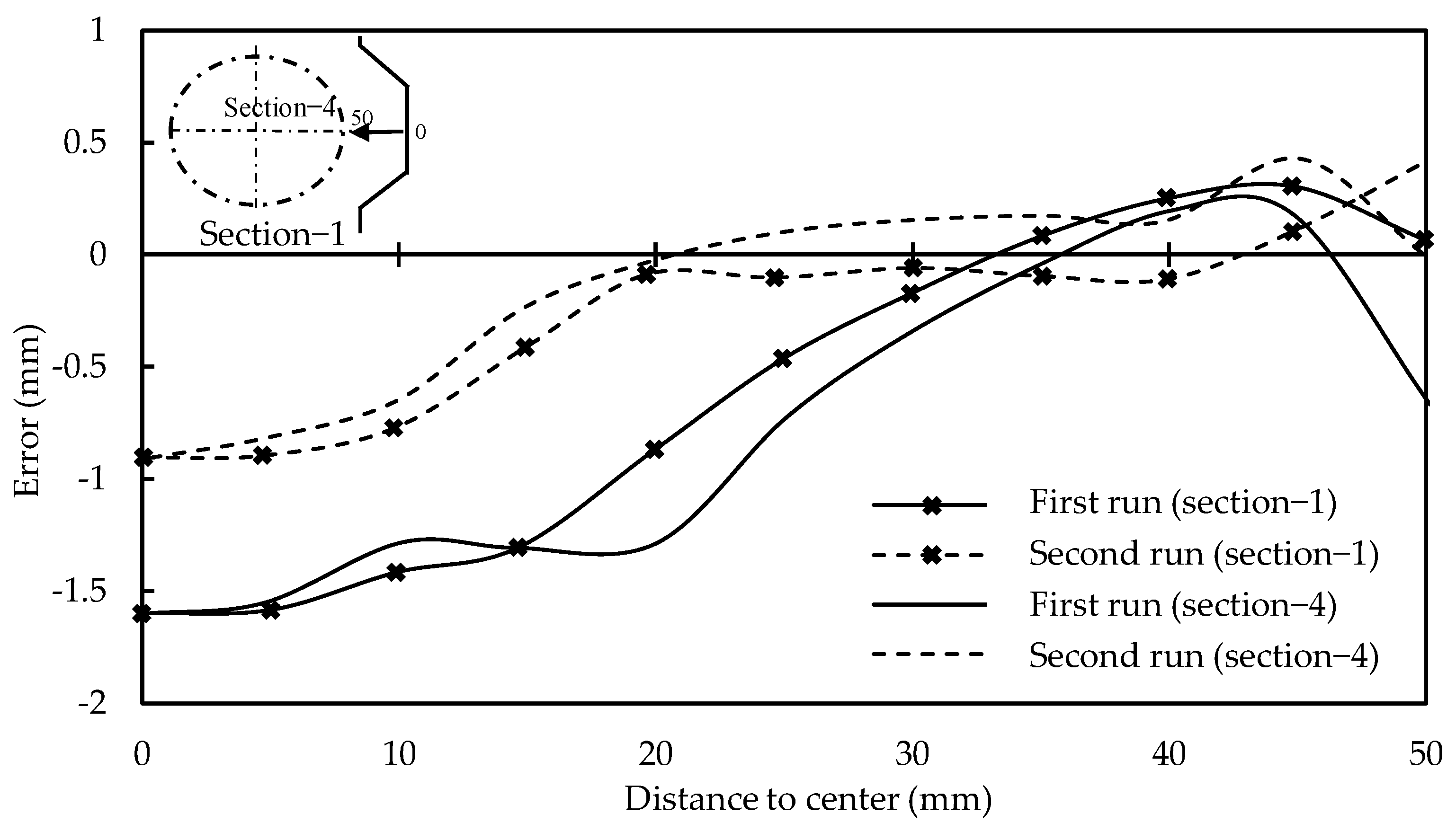
Meier et al. [47] utilized two methods to determine the toolpath deviations from the target path: simulation and optical sensor. Forces determined from the simulation were applied to a multibody system that represented the machine/robot. Toolpath was corrected based on multibody deviation values. With the optical sensor method, part forming was performed in two iterations. In the first iteration, the optical sensor obtained the toolpath deviation. The second compensated toolpath reduced the error significantly (Figure 12). The toolpath deviations include the part springback and machine compliances. Later, Meier et al. [48] presented a complete DSIF toolpath planning and generation procedure.
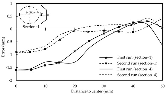
Figure 12.
Accuracy comparison at different sections at first run (with-out compensations) and second run (with compensations), (reprinted with permission from Meier et al. [47], Copyright 2009 Elsevier).
Malhotra et al. [26] formed a cone having dimensions of 130 (diameter) × 36 mm (height) × 65° (wall angle) by using various sets of squeeze factors (1.0, 0.9, and 0.85). The geometric accuracy obtained at a part wall region with DSIF improved compared to SPIF. The faster stabilization of the deformation into a localized zone around the tool’s contact area improved the formability and accuracy. They reported the support tool–sheet lost contact after a certain forming height. Due to the tool–sheet losing contact, the part fractured at approximately 22 mm height, which was less than the required height of 36 mm. For improved geometric accuracy, the gap between the tools should be smaller than the thickness of the contact area; otherwise, it may suffer from the loss of contact between the sheet and the support tool, which will degrade the DPIF process into the SPIF process.
To overcome the tool–sheet contact problem, Moser et al. [27] derived and utilized a toolpath correction algorithm instead of sine law for tool gap determination that incorporates forming height, in-plane curvature, and tools motion direction. Using a novel technique, they efficiently avoided the tool–sheet contact problem and improved the formability to 31.2 mm height. On the other hand, the method is specific to the shamrock component and must be generalized.
Ren et al. [49] utilized the horizontal force control algorithm on the support tool to maintain effective contact with the sheet. The algorithm successfully formed complex components such as a cone, pyramid, funnel, and fish fin. Due to stabilization pressure and successful support tool–sheet contact, the geometric error of the cone was reduced from 2 mm to 1 mm. It improved the 65° funnel formability from 19.1 to 22 mm (15% increase). Ren et al. [50] combined the force control algorithm with the simulation-based in-situ springback method. With the combination of these two strategies, the component’s geometric precision improved substantially (within ±1 mm). The critical technological contribution was the effective identification and utilization of control points. ABAQUS/Explicit was used as the numerical tool to calculate in situ spring back value for these control point to modify the toolpath for spring back compensation. Determining springback compensations from simulations takes time, and implementing the force control approach is complicated. Further work on these two aspects can be helpful in DSIF geometric precision context.
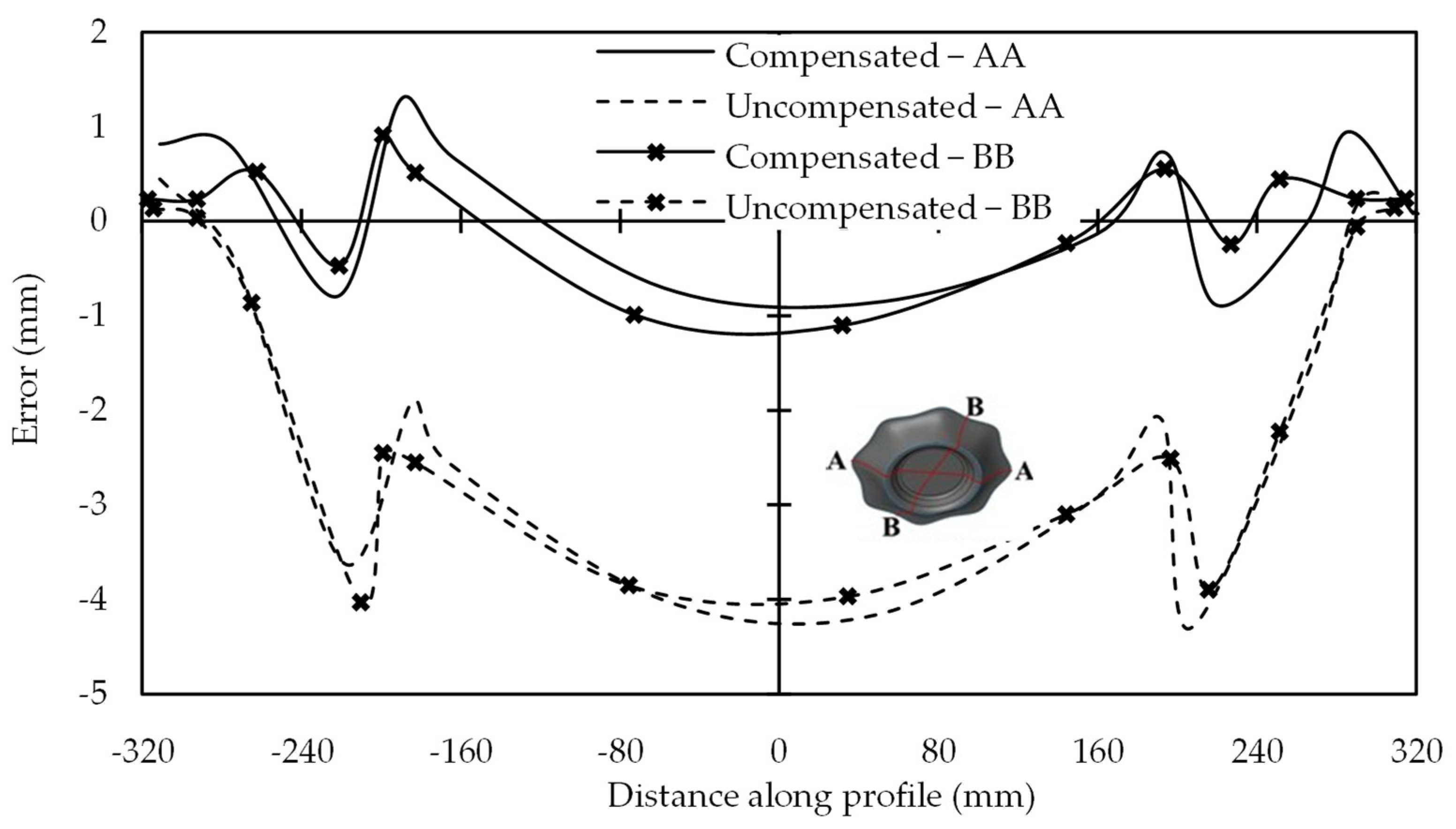
Lingam et al. [23,51] incorporated sheet and tool deflections compensation in the DSIF toolpath and formed components such as cone, funnel, and parabolic. Geometric precision improved both at the wall and the bottom region. The strategy has some limitations (i) it works well for fixture symmetry (ii) deflections should be small compared to sheet thickness, which limits it for a part size up to 200 × 200 mm. Membrane forces experienced by the middle plane of the sheet due to stretching resist the applied transverse load as the sheet deflection increases beyond its thickness. Praveen et al. [52] utilized a combination of small deflection earlier used by Lingam [23,51] and membrane theories to predict and compensate sheet deflections for small and large components. An effective empirical model was developed to estimate large-size components’ sheet and tool deflection. The model was verified by forming geometries such as varying wall angle axisymmetric and a free-form component with a maximum opening size of 610 mm. A compensated toolpath reduced the average error to less than 0.80 mm (Figure 13). Although the accuracy enhanced significantly; however, the support tool did not maintain contact throughout the process due to machine compliances error. The machine tool elements traverse large distances while forming large components; thus, the possibility for an increase in the magnitude of machine tool errors also increases. Konka et al. [53] compensated machine error in the toolpath based on the grid-based method along with the tool and sheet deflection errors. Average accuracy improved further to less than ±0.5 mm. In addition, the support tool had maintained contact with the component throughout the process.
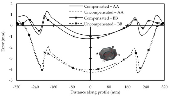
Figure 13.
Error along section AA and BB for the feature of free-form geometry with 610 mm opening (reprinted with permission from Praveen et al. [52], Copyright 2020 Elsevier).
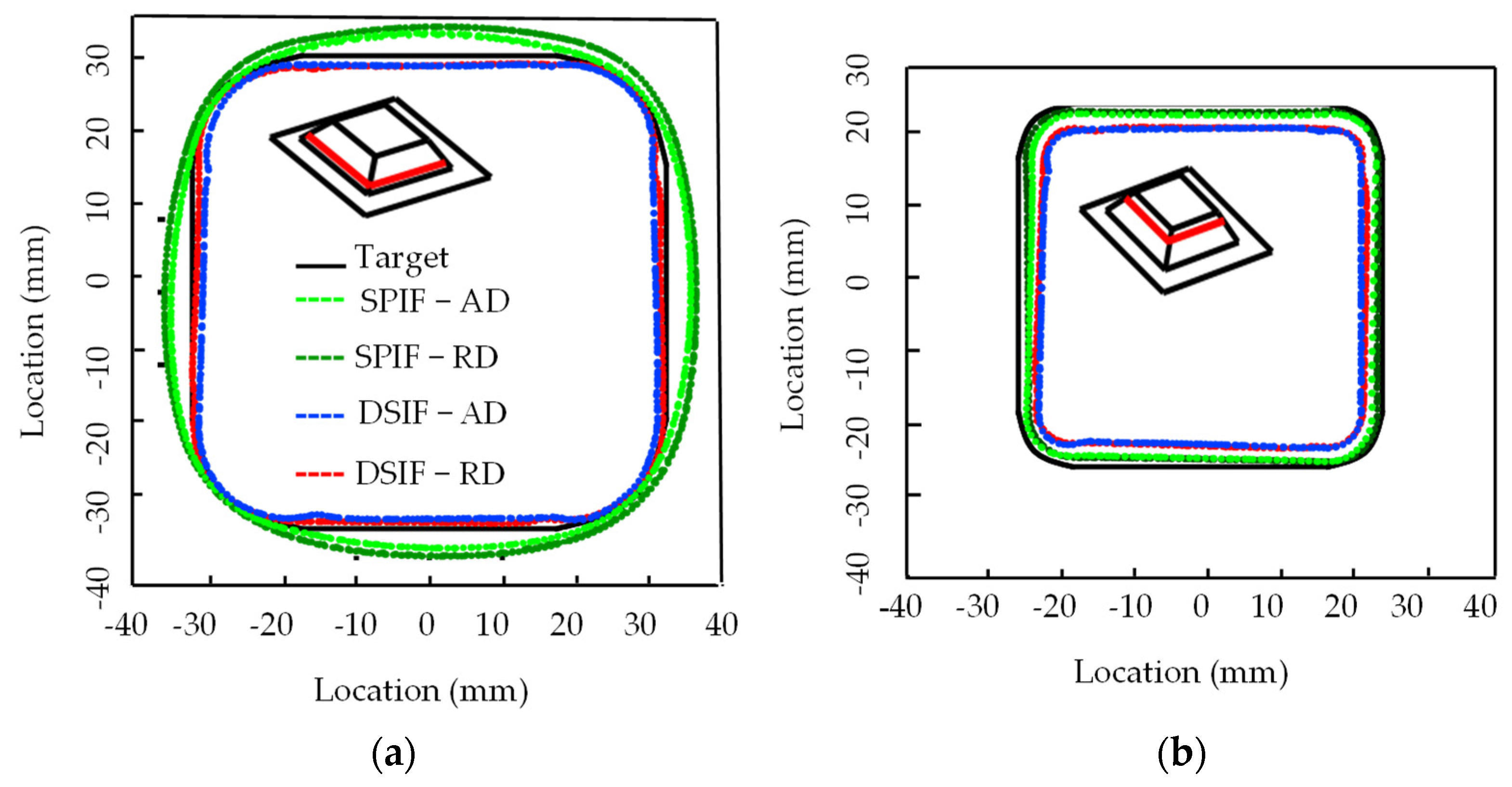
A pyramid with straight walls was considered a challenging shape in DSIF due to the transition from convex to straight-wall region. The master tool–sheet contact area is much larger than the support tool–sheet contact area due to the convex contact between the master tool and the sheet. In this way, although a support tool is employed in the DSIF process, it is only connected with the partial sheet deformation area [54]. With the SPIF and DSIF process, Otsu et al. [29] created a pyramid part with a 70 mm outside diameter and 17 mm height without toolpath compensations (Figure 14). The DSIF process shows the potential for geometric precision improvements compared to SPIF. S. Ullah et al. [22] improved the geometric precision of the pyramid shape for AA7075 and DC04 with the D-DSIF strategy (where D stands for double/dual-stage). They used normal step size in the first stage and incorporated the part error incrementally in the second stage step sizes, which improved the geometric precision to 0.33 mm in AA7075 and 0.57 mm in DC04. In order to maintain a support-tool sheet contact, they utilized the straight-line equation instead of using the sine law only. The D and S changed continuously as the part height increased. The mechanism which possibly degrades the asymmetric component’s geometric accuracy in DSIF was presented. The different circumferential position was trialed for the support tool with respect to the master tool. Based on their study, the support tool should support the master by less than 10° in the circumferential direction in asymmetric components to improve the geometric precision. A higher deviation of the support tool from the master tool local normal can increase the geometric error due to; (i) reverse bending of the sheet due to the support tool lagging movement behind the master tool (ii) ineffective squeezing of the sheet at the required region.
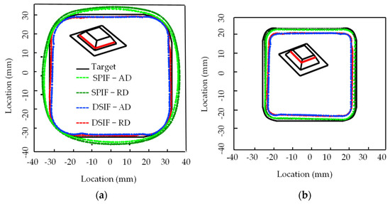
Figure 14.
Horizontal cross-sectional shapes of formed sheet at different heights; (a) height = 3 mm (b) Height = 12 mm, where AD is advancing (clock-wise) direction, RD is retreating (anti-clockwise) direction (reprinted with permission from Otsu et al. [29], Copyright 2018 Elsevier).
Störkle et al. [55] presented an optimized model that can reduce geometric error based on different angles between the tools and the support tool force. However, the application of this model yet needs experimental verifications. Most of the work in this section focused on maintaining tool–sheet contact to improve geometric accuracy. In most cases, formulas, simulations, or algorithms are used for this purpose.
3.2. Geometry Accuracy Improvement by Toolpath Adaptation
In DSIF, the second support tool gives more options for toolpath design. It can benefit from different tool positions, changing toolpath, and adjusting support tool force techniques for accuracy improvement. Table 2 presents some work carried out by researchers for accuracy improvement by toolpath adaptation.
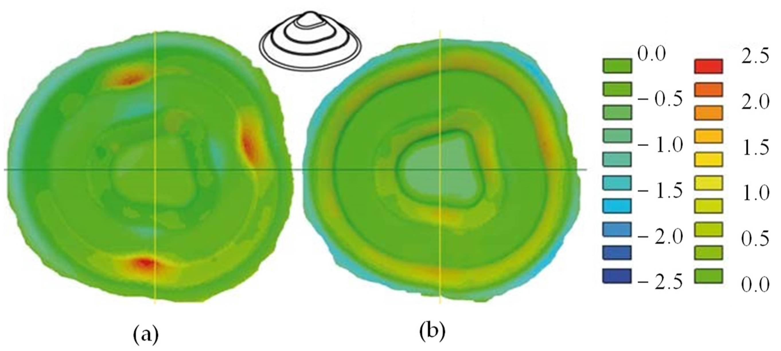
Meier et al. [37] utilized an adjustable support tool capable of applying force on the sheet and master tool to avoid the tool–sheet lost contact problem. The support tool was also capable of orienting its position (angle) to the master tool to find the optimal location. DSIF-L and DSIF-P were trialed with this setup. For DSIF-L, optimal support tool force and position were obtained by trial-and-error experiments. Optimized parameters (support tool force of 300 N and shift angle of 30°) were obtained for the hyperboloid part and were tested on the truncated cone. In DSIF-P, a maximum wall angle of 64° and DSIF-L achieved 72°, increasing the formability by 12.5%. In DSIF-L, the support tool provides enough support (as it was force control) to the master tool, provides greater geometric accuracy than DSIF-P for complex parts (Figure 15). The main limitation of the process was to find the optimal support tool force and angle by trial-and-error tryout procedure for new shape components, which makes the process time-consuming.
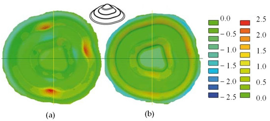
Figure 15.
Geometric accuracy at the (a) DSIF-P (b) DSIF-L process (reprinted with permission from Meier et al. [37], Copyright 2011 Elsevier).
Bin Lu et al. [30] did a similar study for the missing geometry of the defective skull formed from titanium alloy. The geometric error was up to 5 mm at the component opening as utilization of the support tool does not fully compensate for the effect of the backing plate. The error was further aggravated by 3 mm after trimming. It was due to the reduced stiffness around the edge. Although the part geometric error was higher, other ISF techniques struggled to make a component from the titanium. A simulation-based study for a cone was conducted to compare DSIF-L, DSIF-P, and SPIF. In both studies, DSIF-L performed better than DSIF-P [56].
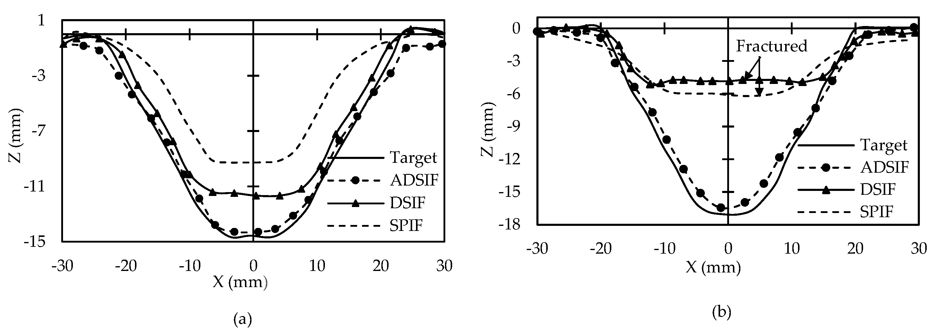
Malhotra et al. [31] introduced a novel ADSIF toolpath strategy to maintain a successful contact between the tool and the sheet. ADSIF and DSIF were compared for cone profiles having 40° and 50° wall angles. Other parameters such as material (AA2024), sheet thickness (0.5 mm), tool diameters, step size (0.025 mm) were kept constant. ADSIF gives better geometric accuracy. DSIF could not form the part with a 50° wall angle as the part fractured earlier (Figure 16). ADSIF faces two challenges (i) better geometric accuracy is obtainable with low step size only (ii) Unlike out-to-in DSIF, the component shape in ADSIF is not directly acquired by the motion of the tools. It is obtained by the accumulation of previous rigid body deformations. The relationship between the desired shape and toolpath parameters is not apparent. For optimal parameters determination, trial and error experimentation is required. Both these limitations make the process time-consuming.
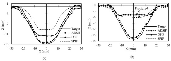
Figure 16.
Comparison of ideal and formed geometries formed using the ADSIF, out-to-in DSIF toolpath and with SPIF for (a) 40° cone and (b) 50° cone (reprinted with permission from Malhotra et al. [31], Copyright 2012 Elsevier).
MDSIF was trialed to overcome the long processing time limitation of ADSIF. It contained ADSIF in the first iteration and DSIF in the second iteration with tool squeezing. Zhang et al. formed a pyramidal part with a concave pocketing on each face with MDSIF having step sizes of 120 μm, 100 μm, and 80 μm. The component geometric precision was compared with DSIF, at a step size of 100 μm and 25 μm. These step sizes (in MDSIF and DSIF) were trialed with squeezing factors of 1, 0.90, 0.80, and 0.75. In DSIF, with the decrease of the squeezing factor, the influence of the reduction of step size on the improvement in geometric accuracy becomes greater. However, it makes the process time-consuming. MDSIF (with a step size of 100 and 80 µm and squeeze factor of 0.8) gives the best result for geometric accuracy. MDSIF almost reduced time consumption with a step size of 100 µm and a squeezing factor of 0.8 to half compared to the ADSIF process with a step size of 25 µm, which took 7 h. Reducing the squeeze factor further to 0.75 in the MDSIF process reduced the accuracy. They observed a deeper-than-designed final part due to the rigid body translation. They reported that fine-tuning of squeeze factor and step size for any machine and part geometry in MDSIF could outperform the DSIF and ADSIF processes [32]. Although the processing time is reduced, it is still more than the conventional-DSIF process. A relationship was developed between the toolpath parameters and desired geometry to overcome the ADSIF second limitations [25]. The approach was specific to the cone part. Some of the inputs, such as relative tool angle and tool gap, were extracted from the experimental setup, making it hard to generalize. Ren et al. [21] reported that ADSIF without machine compliance is less effective than DSIF, whereas compensated ADSIF gives more geometric precision than the compensated DSIF.
Wang et al. [57] utilized a pneumatically-controlled support tool to see the effect of reverse bending and squeezing on a formed part springback. It moves independently with respect to the master tool as it was not position controlled. Reverse bending has a far better effect on springback control than squeezing. It improved the geometric precision to ±0.25 mm. However, over-bending caused by reverse bending leads to a reduced wall angle and accuracy degradation. Deflection in the formed area in Figure 17b was related to the two main factors. First, it may be due to master tool deflection, which paves the way for the support tool to go upward (as pneumatic system provide 300 N force to the support tool regularly to maintain support tool–sheet contact). It leads to over bending of the already formed wall. The second reason they attributed was to the excessive sheet thinning than predicted by Sine law. This excess sheet reduction paves the way for the support tool to go upward. Based on the comparison of 45° and 60° wall angle components, they observed that a large wall angle part would lead to more over bending. They suggested that machines should have fewer compliances or use compensated toolpath to reduce the over-bending effect for such components [58].

Figure 17.
Forces and relative positions of tools in local deformation area in DSIF. (a) Ideal condition; (b) over-bending (reprinted with permission from Peng et al. [58], Copyright 2019 Elsevier).
Zhu et al. [59] studied the continuous contact and points-contact base DSIF. In the points-contact, the support tool made contact with the sheet at those points only for which the master tool coordinates were available. The support tool was disengaged intentionally in the intermediate region. It reduced the error at the part base having prominent indents on the form part at the contact point.
Geometry accuracy improvement for a single feature part cannot guarantee that the DSIF process will work equally well for multiple feature parts. Lingam et al. [60] conducted experiments to demonstrate the effect of feature-forming sequences on geometric accuracy. Forming components from the outer-to-inner direction has shown advantages for geometric accuracy improvements. The stiffness developed in the sheet while processing the outer feature helps in reducing global deformation and improved geometric precision. Lingam et al. [61] further reported a methodology to recognize features from free-form components. To generate a toolpath, the authors sliced the recognized features via horizontal, inclined, or offset strategies. Based on the best feature forming sequence and process mechanics, the maximum deviation between the formed and required geometries was lesser than 400 µm. Ndip-Agbor et al. [62] performed features recognition based on z-level slicing. When features were formed from the inner towards the outer, accuracy was improved as more virgin material was processed. The dichotomous sequence defined by Lingam et al. [61] and Ndip-Agbor et al. [62] may be due to the form part profile difference. Zhu et al. [63] developed an automatic toolpath generation method for multiple feature parts based on stereolithographic (STL). The toolpath for early research was based on the STEP or IGES model to verify their theories. The reason to consider STL-based toolpath was due to its wide applications in rapid prototyping and reverse engineering. A complex part having an upward and downward protrusion on both sides was formed. A maximum error of 3.12 mm was reported and was attributed to springback. STL-based toolpath has the potential to generate an effective toolpath for complex parts.
The forming accuracy improvement in ADSIF with a step size of 25 µm, MDSIF (100 µm), and reverse bending strategy (20 µm) increase the forming time. Various researchers have attempted to shorten the ISF’s long processing time, but no significant improvements, limiting the ISF to prototype and small bath production [64,65]. Although the DSIF process benefited the process forming time due to low tooling requirements, such a small step size can negate the DSIF benefit. Ren et al. [50] tried to reduce the springback with a relatively large step size (0.5 and 1 mm), but instead of correcting each step individually, they did it after a particular forming height. Their work was simulation-dependent, which makes it time-consuming. S. Ullah et al.’s [22] strategy of incrementally incorporating springback in each step (large step size) can improve geometric precision and forming time. To see the effectiveness of their strategy, they compared the four best toolpath strategies based on grey relational analyses on a single platform for geometric precision. The toolpath strategies trialed in their work were DSIF, D-DSIF, ADSIF, and MDSIF. Besides geometric precision, the other quality parameters considered were surface roughness, forming time, and formability. Based on their work, their strategy surpassed the remaining toolpath strategies. Furthermore, changing process parameters and part complexity affect the properties differently [66,67,68,69,70,71]. The post-forming properties evaluation, forming time, and other limitations need to be focused on parallel with geometric precision.
3.3. Geometry Accuracy Improvement by Multi-Pass DSIF
Material distribution by multi-stage toolpath strategies can be obtained, especially for high wall angle components. The low wall angle’s part deformed without decreasing the thickness substantially as more material is available for processing. In the high wall angle part, the sheet becomes thin as a small sheet region is available for forming. Zhang et al. [72] formed a clover flange by incrementally increasing the diameter in each pass. Geometrical accuracy improved at the stretch flange without acquiring the required height. The forming height error was due to an interaction between the stretch flange and the shrink flange. For shrink flange, the geometric error was 3.76 mm. Moser et al. [28] utilize multi-stage DSIF (corner pushing strategy and flat bottom strategy) for a cylindrical part having a diameter of 60 mm and height of 28 mm from the aluminum. In the corner pushing strategy, the sheet metal was pushed into the corner, whereas in the flat bottom approach, the flat bottom depth was increased in the subsequent step. The corner push strategy gives a maximum wall angle of 72°, having geometric error up to 10 mm at the part bases. Increasing the wall angle between subsequent stages can result in wrinkling, leading to form part in more stages. The flat bottom yielded 86° and reduced the error at the part base. Upon reducing the number of passes in the flat bottom strategy, the part fractured at 82°. The number of passes required in both techniques increased the processing time than the normal DSIF process. They observed that increasing the total number of stages increases the maximum achievable wall angle at the cost of additional rigid body translations, which are difficult to predict. In addition, the prediction of material thinning is not solely dependent on the wall angle or geometric features, which adds to the challenge of maintaining tool contact with the part being formed.
3.4. Geometry Accuracy Improvement by Heat-Assisted DSIF
The desired geometry is formed by deforming the metal to yield stress at the required region. The yield stress of a material has a relation with temperature. Generally, the yield stress and temperature have an inverse relationship [73]. Increasing temperature results in lower forming forces provided the constant strain rate. In ISF, researchers utilized this factor for formability and accuracy improvement of the metal. Many researchers used the heat-assisted SPIF process for metal forming [74,75,76]. Due to its flexible nature, heat-assisted DSIF is also trailed, especially for hard-to-form material. Springback during the forming process in such metals is one of the reasons for inaccurate geometric accuracy. Attempts made by researchers to overcome this issue during forming are as shown in Table 3.
Meier and Magnus [77] trialed DX54D at 600 °C with SPIF, heat-assisted SPIF, and DSIF. Part accuracy was out of scale for SPIF and heat-assisted SPIF. The error was reduced to 1 mm in the component formed with the heat-assisted DSIF process. Asghar and Reddy [73] formed a pyramid from the titanium by utilizing a high-density pulse current in DSIF. The tool-setting was changed from the normal to align configuration after 6.35 mm part height. The part was formed up to 25 mm successfully. It was reportedly the first trial of titanium forming with DSIF; therefore, the component accuracy was not reported. The main focus of their study was formability improvement.
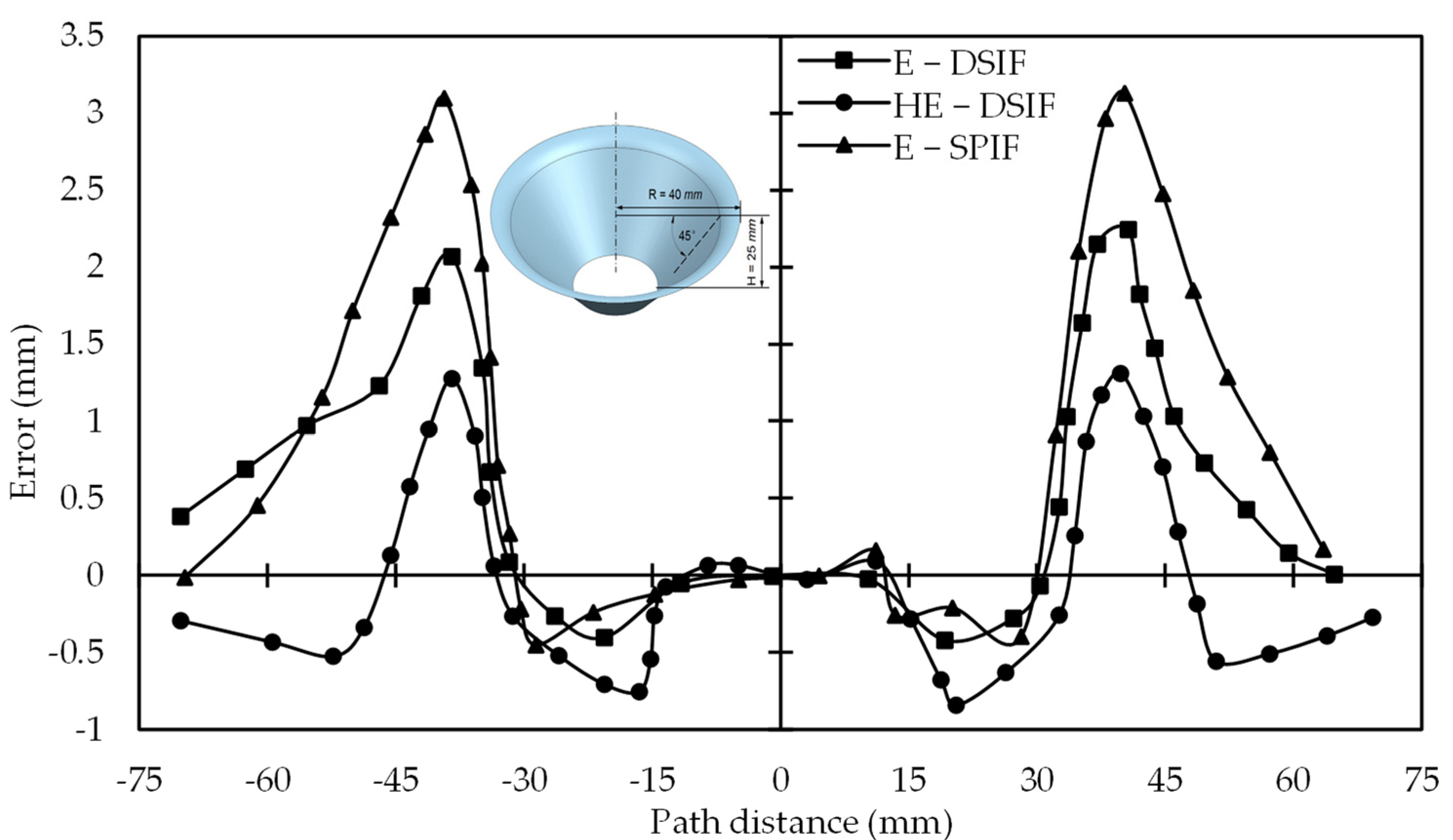
Hybrid-EDSIF, E-DSIF, and E-SPIF (E is for electric) were used to form a cone from AZ3B1. In hybrid E-DSIF, for the fillet region at the part opening, the toolpath mode was DSIF-P. After deforming the fillet, the toolpath mode switched to DSIF-L. Minimum springback was observed in part formed with HE-DSIF. Its geometric accuracy improved significantly as the average error was less than 1 mm (Figure 18). Their work compared the error after unclamping and trimming, although the geometric error during forming took the most significant error percentage. Geometric error in the part after unclamping and trimming could decrease with E-DSIF. They also pointed out that the materials with more significant electrical resistance will be energy efficient in the E-DSIF [78].
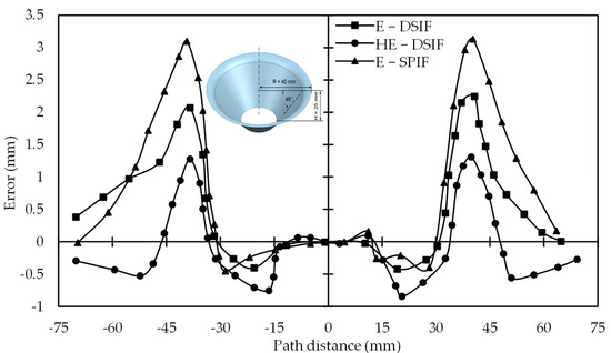
Figure 18.
Geometric error in formed part in clamped position for E-SPIF, E-DSIF, and HE-DSIF (reprinted with permission from Xu et al. [78], Copyright 2016 Elsevier).
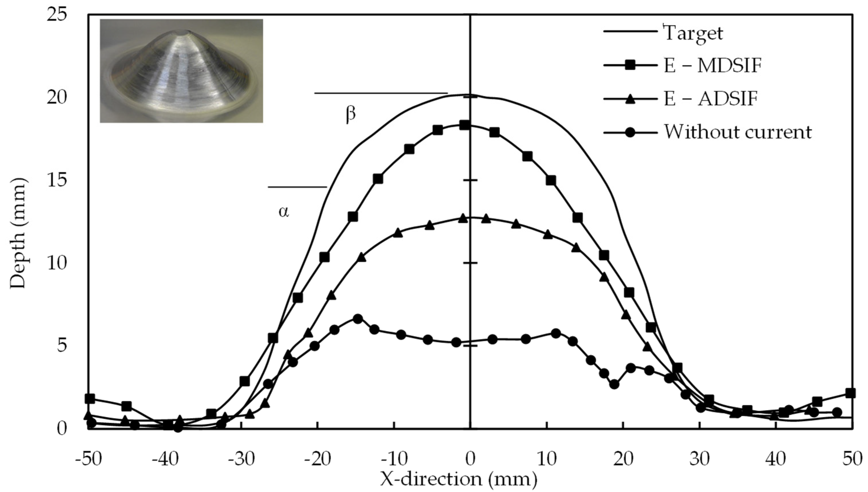
Valoppi et al. [79] deformed Ti6Al4V alloy at room temperature and observed a crack at 4.58 mm forming height. Electric-assisted ADSIF and MDSIF were used to make the same parts. ADSIF has the advantage in the electric-assisted process as it can maintain consistent tool contact during forming with the sheet to avoid sparking. Formed parts with both strategies were compared at different current levels. For geometry accuracy and formability improvement, E-MDSIF outperformed the E-ADSIF (Figure 19). In MDSIF (ADSIF + DSIF), material first moved from the inner to the outer circumference in the E-ADSIF stage and redistributed material during the E-DSIF. It was due to the two-stage forming. Valoppi et al. [39] emphasized the support tool design improvement to expand the compressive area between the tools. It can enhance formability, which can lead to better geometric precision.
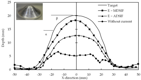
Figure 19.
Formed part geometric error comparison (where α = 50°, β = 20°) (reprinted with permission from Valoppi et al. [79], Copyright 2016 Elsevier).
Kiridena et al. [80] investigated post-process springback reduction by utilizing eclectic assisted processes. Three configurations were tested: through-thickness, path base, and area base treatment. The area-based configuration gave the best qualitative results; however, it was the least energy efficient. Though the through-thickness technique was energy efficient; however, it required fine-tuning and made it time-consuming. Zhang et al. [81] investigated the post-process springback reduction on the component formed with the SPIF process. Under ideal conditions, the stress-relief annealing procedure reduces post-process springback (250 °C and 1 h). An adverse effect on the springback reduction was observed when the part temperature was increased from the optimal temperature. Post-process springback reduction techniques can be integrated with all the ISF variants. Although heat-assisted methods have improved the formability of hard-to-form metals, high residual stresses may arise during the forming process due to cyclic expansion and contraction, which can impair material strength.
3.5. Forces Effects on Geometric Precision Improvement
Sheet squeezing between the tools is the most significant factor differentiating the DSIF from the SPIF process. It is clear from the literature that keeping the support tool in contact with the sheet enhanced geometric precision. To maintain the tool–sheet contact, researchers usually used two strategies (a) squeezing by a gap (SBG) (b) squeezing by pressure (SBP). SBP strategies utilize a pneumatic jack or robotic arm for the support tool to apply force to ensure the support tool contact with the sheet. Table 4 displays the master and support tool forces for various toolpaths (M for master, S for support in Z-direction, MR, and SR for master and support tool force in a radial plane). Type of toolpath, step size, tool diameter, feed rate, and material type are listed from the literature to obtain the ideas about the forces required for different strategies and under what circumstances. It is evident from the table that SBG strategies can be applied to toolpath compensation and adaption equally.

Table 4.
Master and support tool force requirements in different toolpath strategies.
Regarding SBG strategies, Malhotra et al. [26] observed that the master tool force was in the range of 1200–1400 N when the support tool was in contact with the sheet. As soon as the support tool disengaged from the sheet, the rapid loss in force became apparent. Ren et al. [49] used the horizontal force control algorithm on the support tool to ensure the support tool’s contact in the radial direction (XY plane). Continuous contact of the support tool with the sheet increased the formability of complex components. Lingam et al. [23,51], Praveen et al. [52], and Konka et al. [53] utilized the empirical formula for tool and sheet deflection determination and calculated the forming forces. The compensated master tool toolpath based on empirical formula ensured 50–70 N force contact between the support tool and the sheet. With this small support tool force, they improved geometric precision and formability. They manufactured the large industrial part successfully. Malhotra et al. [31] utilized an ADSIF strategy. With a 0.5 mm thick sheet, the force requirement in ADSIF in Z-direction is about 425 N for the master tool and 280 N for the support tool. The in-plane force requirement was reported higher (220–274 N for the master and 80–160 N for the support tool) in ADSIF, and it is as large as the Z-direction. These are larger forces with the smaller step size, tool diameter, and less sheet thickness (these conditions usually lead to fewer force requirements [13]). In thick sheets, the forces required may increase, lowering process energy efficiency and maximizing master tool deflection which can decrease ADSIF geometric precision. The second D-stage of MDSIF increases the support tool force to 200 N upon squeezing the sheet by 0.80 times. The squeezing of the already treated stiff sheet with ADSIF causes an increase in support tool force [82].
Regarding SBP strategies, Meier et al. [37] utilized a support tool force of 125 N. Although the support tool contact improved the geometric precision; however, the trial-and-error procedure to find the optimal force value along with tools ideal location is time-consuming. Wang et al. [57] utilized the pneumatically supported tool. The higher support force provided by the pneumatic jack has improved the formability of the most challenging material. The step size is small (after the ADSIF) and can lead to more forming time.
In SBG strategy, the support tool force requirement is higher for toolpath adaption strategies such as ADSIF and MDSIF. These higher forces are with small step sizes. Increasing the step size will further increase the force requirement and degrade the geometric precision. The toolpath compensation strategy works well with SBG strategies, as it leads to low support tool forces requirement with a large step size. The larger step size may reduce the forming time, whereas the low support tool force may help in improving the surface roughness. SBP strategy can improve the formability more effectively; however, it can degrade the surface roughness.
The master and support tool forces may be uniform for the axis-symmetric components. For asymmetric, the forces required for both tools may change at different sections of the part as the master tool force requirement for the pyramid varied at different positions in SPIF [83]. While working on commandant force for the support tool in the XY plane for improving geometric precision and formability, Ren et al. [49] observed the force variation in the range of 100–200 N for the pyramid shape, whereas it was the same for cone and funnel (axis-symmetric component). The support tool force variation for complex profiles makes the force control method unreliable and difficult to implement for geometric precision improvements.
In SPIF, a detailed study regarding the relation of the forces with different parameters such as step size, tool diameter, and sheet material thickness is reported. The forming forces requirement increased as the tool diameter, wall angle, incremental step size, and sheet thickness increased [84,85,86,87,88,89]. From Table 4, it is evident that there is no systematic study regarding the forces on the tool. One reason may be the DSIF’s flexible nature as it can be conveniently adjusted to any success in SPIF or TPIF. In DSIF, besides the four factors (tool diameter, wall angle, incremental step size, and sheet thickness) studied extensively in SPIF, the support tool is seemed to have significant relation with the master tool forces requirement. Increasing support tool forces can increase the master tool force requirements, which require further research to improve the process’s geometric precision, as increasing forces can increase the tool deflections.
The unsatisfied surface quality by ISF is the most investigated factor with geometric precision, which has impeded the process application in the industrial sector. It is critical to determine the impact of different process parameters on surface roughness with geometric precision. The primary influence of tool diameter and step size, and the secondary effects of lubricant type, spindle speed, and feed rate, were reported in SPIF and TPIF [90,91,92,93,94,95,96]. The impact of tool profiles, such as hemispherical and rolling tools, was also examined [97,98]. Skjoedt et al. [99] and Li et al. [7] improved the surface roughness with interpolators in SPIF and TPIF. The interpolator is the additional thin sheet between the tool and the required sheet. The interpolator used in TPIF for surface roughness improvement can be extended to DSIF to check its effectiveness for geometric precision along with surface roughness improvement. Li et al. [7] reported that interpolator does not affect the forming forces requirement in TPIF. In DSIF, due to the additional flexible support tool, interpolators on both sides can affect the forming force requirement. The utilization of an ultrasonic-assisted technique [100] in conjunction with an interpolator can improve surface roughness and geometric precision.
4. Discussion and Future Work Recommendations
DSIF is still neglected at an industrial scale due to its low geometric accuracy compared to conventional sheet metal forming methods. Regarding formability, DSIF has better results than traditional sheet metal forming. Surface roughness and long processing time, which are also the main challenges in DSIF, are not focused on to date. Regarding geometric precision, researchers have implemented optimal techniques and achieved better results. However, these techniques are not generalized or sometimes difficult to be incorporated into the process. Discussion and future work based on the insight from the articles as mentioned earlier are as follow:
- In the DSIF process, the lost contact between the tool and the sheet due to the inaccurate tool gap predicted by sine law is one of the reasons for the part geometric error. The tool gap is usually calculated with sine law, which only considers the wall angle and is not enough to predict accurate wall thickness. Some researchers established modified sine law. They included part height, curvature, and wall angle, but these studies were limited to specific parts. A generalized formula or method should be derived, which could predict the wall thickness precisely for any geometric shape accurately.
- Apart from the sine law, the stiffness variation in metal during forming also plays a role in contact loss. Following the pre-defined toolpath, the reduced reaction force for the support tool can be observed during the forming process. Support tool deviations from the component should be considered an online error in the under-process part. The enhanced stiffness in the sheet during forming applies a load on the master tool. It deviates the master tool from the designed toolpath due to increasing stiffness. Some researchers compensated the master tool toolpath based on empirical formulas and obtained good geometric precision to accommodate such errors. It should be extended to other processes and material parameters. Besides, some methods for stiffness calculation or reduction can be beneficial. The ultrasonic-assisted DSIF process is still not trialed in DSIF, while it has successfully reduced the forming force in other ISF variants due to the acoustoplastic softening effect [100].
- The relative position between the master and support tool is adjustable due to the flexible support tool in DSIF, which gives more options for toolpath alteration than SPIF or TPIF. ADSIF results from such alterations, which resolves the tool–sheet lost contact problems effectively. It alters the conventional toolpath sequence used in DSIF. The gap between the two tools is not an issue as virgin material is always processed. The geometric accuracy obtained with ADSIF surpasses other strategies. However, ADSIF has some limitations as long processing time and complicated toolpath design. Support tool position determination is not as flexible as in the conventional-DSIF process and is determined for each profile by the trial-and-error procedure. Some researchers had trialed to introduce generalized methods for these shortcomings. However, to date, no generalized method established. It needs further improvements to take full benefits from it. The strategy which is dependent on ADSIF as MDSIF can be improved if ADSIF limitations are solved.
- The DSIF process should be expanded to larger, thicker, and asymmetric components to increase the DSIF process’s industrial viability. Researchers enhanced part precision and formability by successfully preserving tool–sheet contact while using sheet thickness of 1 mm or less for symmetric components in most circumstances. Besides this, the part size formed in most cases is less than 100 mm. Geometric precision in asymmetric parts is more difficult due to the transition from convex to straight and convex to concave regions, and it is the least studied area in DSIF. To obtain acceptability in the industrial sector, all of these constraints must be addressed efficiently.
- TPIF gives good geometric accuracy if compared with DSIF and SPIF. To date, no direct comparison for TPIF and DSIF. In TPIF, the die provides essential support to the master tool wherever required. However, in DSIF, a limited region of the master tool is supported. Due to this limitation, researchers trialed DSIF-P, DSIF-L, squeezing, reverse bending, etc. There is a dire need to design a support tool that can provide simultaneous support to the master tool wherever required. Besides, the optimal support tool force required for geometric precision improvement needs investigations.
- Springback is the foremost geometric error source in ISF. DSIF can reduce springback if the sheet is squeezed between the tools tactically. In ISF, elastic deformation recovers back as tools leave the formed region. In individual steps, the error due to elastic recovery may be negligible. The accumulation of springback for each step, on the other hand, leads to significant inaccuracies. Elastic recovery compensation in each step size can reduce springback error in the form part; nevertheless, forming in two stages can increase the forming time. Numerical or analytical techniques for calculating elastic recovery for a single step size can simplify a two-stage forming process to a single-stage procedure. A numerical or analytical approach for calculating elastic recovery for a single step size needs investigation.
Author Contributions
S.U., Conceptualization, Data Curation, Methodology, Formal analysis, Investigation, Writing—Original Draft; P.X., Data Curation, Methodology; X.L., Conceptualization and Data Curation, Funding acquisition, Supervision.; Y.L., Conceptualization and Data Curation, Formal analysis, Writing—Review & Editing, Funding acquisition, Visualization, Supervision; K.H., Visualization; D.L., Supervision, Project administration. All authors have read and agreed to the published version of the manuscript.
Funding
This work is supported by the National Natural Science Foundation of China (52075025, 51975328), and the Project funded by the China Postdoctoral Science Foundation (2021T140418).
Institutional Review Board Statement
Not applicable.
Informed Consent Statement
Not applicable.
Data availability statement: Not applicable.
Acknowledgments
We would like to take this opportunity to acknowledge the time and effort devoted by reviewers to improve the manuscript quality.
Conflicts of Interest
The authors declare no conflict of interest.
References
- Duflou, J.R.; Habraken, A.-M.; Cao, J.; Malhotra, R.; Bambach, M.; Adams, D.; Vanhove, H.; Mohammadi, A.; Jeswiet, J. Single point incremental forming: State-of-the-art and prospects. Int. J. Mater. Form. 2017, 11, 743–773. [Google Scholar] [CrossRef]
- Jeswiet, J.; Micari, F.; Hirt, G.; Bramley, A.; Duflou, J.; Allwood, J. Asymmetric Single Point Incremental Forming of Sheet Metal. CIRP Ann. 2005, 54, 88–114. [Google Scholar] [CrossRef]
- Allwood, J.; Music, O.; Raithathna, A.; Duncan, S.R. Closed-loop feedback control of product properties in flexible metal forming processes with mobile tools. CIRP Ann. 2009, 58, 287–290. [Google Scholar] [CrossRef]
- Allwood, J.M.; Braun, D.; Music, O. The effect of partially cut-out blanks on geometric accuracy in incremental sheet forming. J. Mater. Process. Technol. 2010, 210, 1501–1510. [Google Scholar] [CrossRef]
- Nasulea, D.; Oancea, G. Achieving Accuracy Improvements for Single-Point Incremental Forming Process Using a Circumferential Hammering Tool. Metals 2021, 11, 482. [Google Scholar] [CrossRef]
- Hussain, G.; Gao, L. A novel method to test the thinning limits of sheet metals in negative incremental forming. Int. J. Mach. Tools Manuf. 2007, 47, 419–435. [Google Scholar] [CrossRef]
- Li, X.; Han, K.; Song, X.; Wang, H.; Li, D.; Li, Y.; Li, Q. Experimental and numerical investigation on surface quality for two-point incremental sheet forming with interpolator. Chin. J. Aeronaut. 2020, 33, 2794–2806. [Google Scholar] [CrossRef]
- Wei, H.; Hussain, G.; Shi, X.; Isidore, B.B.L.; Alkahtani, M.; Abidi, M.H. Formability of Materials with Small Tools in Incremental Forming. Chin. J. Mech. Eng. 2020, 33, 1–9. [Google Scholar] [CrossRef]
- Behera, A.K.; Verbert, J.; Lauwers, B.; Duflou, J.R. Tool path compensation strategies for single point incremental sheet forming using multivariate adaptive regression splines. Comput. Des. 2012, 45, 575–590. [Google Scholar] [CrossRef]
- Lasunon, O.; Knight, W.A. Comparative investigation of single-point and double-point incremental sheet metal forming processes. Proc. Inst. Mech. Eng. Part B J. Eng. Manuf. 2007, 221, 1725–1732. [Google Scholar] [CrossRef]
- Park, J.-J.; Kim, Y.-H. Fundamental studies on the incremental sheet metal forming technique. J. Mater. Process. Technol. 2003, 140, 447–453. [Google Scholar] [CrossRef]
- Reddy, N.V.; Lingam, R.; Cao, J. Incremental metal forming processes in manufacturing. In Handbook of Manufacturing Engineering and Technology; Nee, A.Y.C., Ed.; Springer: London, UK, 2014; pp. 411–452. [Google Scholar] [CrossRef]
- Behera, A.K.; de Sousa, R.A.; Ingarao, G.; Oleksik, V. Single point incremental forming: An assessment of the progress and technology trends from 2005 to 2015. J. Manuf. Process. 2017, 27, 37–62. [Google Scholar] [CrossRef]
- Li, Y.; Chen, X.; Liu, Z.; Sun, J.; Li, F.; Li, J.; Zhao, G. A review on the recent development of incremental sheet-forming process. Int. J. Adv. Manuf. Technol. 2017, 92, 2439–2462. [Google Scholar] [CrossRef]
- Ai, S.; Long, H. A review on material fracture mechanism in incremental sheet forming. Int. J. Adv. Manuf. Technol. 2019, 104, 33–61. [Google Scholar] [CrossRef]
- Lu, H.; Liu, H.; Wang, C. Review on strategies for geometric accuracy improvement in incremental sheet forming. Int. J. Adv. Manuf. Technol. 2019, 102, 3381–3417. [Google Scholar] [CrossRef]
- Peng, W.; Ou, H.; Becker, A. Double-Sided Incremental Forming: A Review. J. Manuf. Sci. Eng. 2019, 141, 1–42. [Google Scholar] [CrossRef]
- Gohil, A.; Modi, B. Review of the effect of process parameters on performance measures in the incremental sheet forming process. Proc. Inst. Mech. Eng. Part B J. Eng. Manuf. 2020, 235, 303–332. [Google Scholar] [CrossRef]
- Tomasz Trzepieci, N.; Oleksik, V.; Pepelnjak, T.; Mohammed Najm, S.; Paniti, I.; Kuntal, M. Emerging Trends in Single Point Incremental Sheet Forming of Lightweight Metals. Metals 2021, 11, 1188. [Google Scholar] [CrossRef]
- Smith, J.; Malhotra, R.; Liu, W.K.; Cao, J. Deformation mechanics in single-point and accumulative double-sided incremental forming. Int. J. Adv. Manuf. Technol. 2013, 69, 1185–1201. [Google Scholar] [CrossRef]
- Ren, H.; Moser, N.; Zhang, Z.; Ehmann, K.F.; Cao, J. Effects of tool deflection in accumulated double-sided incremental forming regarding part geometry. In Proceedings of the ASME 2016 11th International Manufacturing Science and Engineering Conference, Blacksburg, VA, USA, 27 June 2016; pp. 1–9. [Google Scholar] [CrossRef]
- Ullah, S.; Li, X.; Xu, P.; Li, Y.; Han, K.; Li, D. A toolpath strategy for improving geometric accuracy in double-sided incremental sheet forming. Chin. J. Aeronaut. 2021. [Google Scholar] [CrossRef]
- Lingam, R.; Bhattacharya, A.; Asghar, J.; Reddy, N.V. Compensations for tool path to enhance accuracy during double sided incremental forming. In Proceedings of the ASME 2015 International Manufacturing Science and Engineering Conference, Charlotte, NC, USA, 8–12 June 2015; pp. 1–8. [Google Scholar] [CrossRef]
- Meier, H.; Smukala, V.; Dewald, O.; Zhang, J. Two Point Incremental Forming with Two Moving Forming Tools. Key Eng. Mater. 2007, 344, 599–605. [Google Scholar] [CrossRef]
- Ndip-Agbor, E.; Smith, J.; Ren, H.; Jiang, Z.; Xu, J.; Moser, N.; Chen, W.; Xia, Z.C.; Cao, J. Optimization of relative tool position in accumulative double sided incremental forming using finite element analysis and model bias correction. Int. J. Mater. Form. 2015, 9, 371–382. [Google Scholar] [CrossRef]
- Malhotra, R.; Cao, J.; Ren, F.; Kiridena, V.; Xia, Z.C.; Reddy, N. Improvement of Geometric Accuracy in Incremental Forming by Using a Squeezing Toolpath Strategy with Two Forming Tools. J. Manuf. Sci. Eng. 2011, 133, 061019. [Google Scholar] [CrossRef]
- Moser, N.; Zhang, Z.; Ren, H.; Zhang, H.; Shi, Y.; Ndip-Agbor, E.E.; Lu, B.; Chen, J.; Ehmann, K.F.; Cao, J. Effective forming strategy for double-sided incremental forming considering in-plane curvature and tool direction. CIRP Ann. 2016, 65, 265–268. [Google Scholar] [CrossRef]
- Moser, N.; Ndip-Agbor, E.; Ren, H.Q.; Zhang, Z.X.; Ehmann, K.; Cao, J. Challenges and Process Strategies Concerning Multi-Pass Double Sided Incremental Forming. Key Eng. Mater. 2015, 651–653, 1122–1127. [Google Scholar] [CrossRef]
- Otsu, M.; Nagai, S.-Y.; Miura, T.; Okada, M.; Yoshimura, H.; Matsumoto, R.; Muranaka, T. Forming accuracy improvement by double-side incremental forming. Procedia Manuf. 2018, 15, 1177–1183. [Google Scholar] [CrossRef]
- Lu, B.; Xu, D.K.; Liu, R.Z.; Ou, H.A.; Long, H.; Chen, J. Cranial Reconstruction Using Double Side Incremental Forming. Key Eng. Mater. 2015, 639, 535–542. [Google Scholar] [CrossRef]
- Malhotra, R.; Cao, J.; Beltran, M.; Xu, D.; Magargee, J.; Kiridena, V.; Xia, Z.C. Accumulative-DSIF strategy for enhancing process capabilities in incremental forming. CIRP Ann. 2012, 61, 251–254. [Google Scholar] [CrossRef]
- Zhang, Z.; Ren, H.; Xu, R.; Moser, N.; Smith, J.; Ndip-Agbor, E.; Malhotra, R.; Xia, Z.C.; Ehmann, K.F.; Cao, J. A Mixed Double-Sided Incremental Forming Toolpath Strategy for Improved Geometric Accuracy. J. Manuf. Sci. Eng. 2015, 137, 051007. [Google Scholar] [CrossRef]
- Choi, H.; Lee, C. A mathematical model to predict thickness distribution and formability of incremental forming combined with stretch forming. Robot. Comput. Manuf. 2018, 55, 164–172. [Google Scholar] [CrossRef]
- Salem, E.; Shin, J.; Nath, M.; Banu, M.; Taub, A.I. Investigation of Thickness Variation in Single Point Incremental Forming. Procedia Manuf. 2016, 5, 828–837. [Google Scholar] [CrossRef]
- Cao, T.; Lu, B.; Xu, D.; Zhang, H.; Chen, J.; Long, H.; Cao, J. An efficient method for thickness prediction in multi-pass incremental sheet forming. Int. J. Adv. Manuf. Technol. 2014, 77, 469–483. [Google Scholar] [CrossRef]
- Mirnia, M.J.; Dariani, B.M.; Vanhove, H.; Duflou, J.R. An investigation into thickness distribution in single point incremental forming using sequential limit analysis. Int. J. Mater. Form. 2013, 7, 469–477. [Google Scholar] [CrossRef]
- Meier, H.; Magnus, C.; Smukala, V. Impact of superimposed pressure on dieless incremental sheet metal forming with two moving tools. CIRP Ann. 2011, 60, 327–330. [Google Scholar] [CrossRef]
- Lu, B.; Fang, Y.; Xu, D.; Chen, J.; Ai, S.; Long, H.; Ou, H.; Cao, J. Investigation of material deformation mechanism in double side incremental sheet forming. Int. J. Mach. Tools Manuf. 2015, 93, 37–48. [Google Scholar] [CrossRef]
- Valoppi, B.; Zhang, Z.; Deng, M.; Ghiotti, A.; Bruschi, S.; Ehmann, K.F.; Cao, J. On the Fracture Characterization in Double-Sided Incremental Forming of Ti6Al4V Sheets at Elevated Temperatures. Procedia Manuf. 2017, 10, 407–416. [Google Scholar] [CrossRef]
- Zhang, H.; Zhang, Z.; Ren, H.; Cao, J.; Chen, J. Deformation mechanics and failure mode in stretch and shrink flanging by double-sided incremental forming. Int. J. Mech. Sci. 2018, 144, 216–222. [Google Scholar] [CrossRef]
- Moser, N.; Zhang, Z.; Ren, H.; Ehmann, K.; Cao, J. An investigation into the mechanics of double-sided incremental forming using finite element methods. AIP Conf. Proc. 2016, 1769, 070021. [Google Scholar] [CrossRef]
- Malhotra, R.; Xue, L.; Belytschko, T.; Cao, J. Mechanics of fracture in single point incremental forming. J. Mater. Process. Technol. 2012, 212, 1573–1590. [Google Scholar] [CrossRef]
- Davarpanah, M.A.; Zhang, Z.; Bansal, S.; Cao, J.; Malhotra, R. Preliminary investigations on Double Sided Incremental Forming of thermoplastics. Manuf. Lett. 2016, 8, 21–26. [Google Scholar] [CrossRef]
- Micari, F.; Ambrogio, G.; Filice, L. Shape and dimensional accuracy in Single Point Incremental Forming: State of the art and future trends. J. Mater. Process. Technol. 2007, 191, 390–395. [Google Scholar] [CrossRef]
- Wang, Y.; Huang, Y.; Cao, J.; Reddy, N.V. Experimental study on a new method of double side incremental forming. In Proceedings of the ASME 2008 3rd International Manufacturing Science and Engineering Conference, Evanston, IL, USA, 7–10 October 2008. [Google Scholar] [CrossRef]
- Wang, Y.; Wu, W.; Huang, Y.; Reddy, N.V.; Cao, J. Experimental and numerical analysis of double sided incremental forming. In Proceedings of the ASME 2009 International Manufacturing Science and Engineering Conference, West Lafayette, IN, USA, 4–7 October 2009. [Google Scholar] [CrossRef]
- Meier, H.; Buff, B.; Laurischkat, R.; Smukala, V. Increasing the part accuracy in dieless robot-based incremental sheet metal forming. CIRP Ann. 2009, 58, 233–238. [Google Scholar] [CrossRef]
- Meier, H.; Zhu, J.; Buff, B.; Laurischkat, R. CAx Process Chain for Two Robots Based Incremental Sheet Metal Forming. Procedia CIRP 2012, 3, 37–42. [Google Scholar] [CrossRef]
- Ren, H.; Li, F.; Moser, N.; Leem, D.; Li, T.; Ehmann, K.; Cao, J. General contact force control algorithm in double-sided incremental forming. CIRP Ann. 2018, 67, 381–384. [Google Scholar] [CrossRef]
- Ren, H.; Xie, J.; Liao, S.; Leem, D.; Ehmann, K.; Cao, J. In-situ springback compensation in incremental sheet forming. CIRP Ann. 2019, 68, 317–320. [Google Scholar] [CrossRef]
- Rakesh, L.; Amit, S.; Reddy, N.V. Deflection Compensations for Tool Path to Enhance Accuracy During Double-Sided Incremental Forming. J. Manuf. Sci. Eng. 2016, 138, 091008. [Google Scholar] [CrossRef]
- Praveen, K.; Lingam, R.; Reddy, N.V. Tool path design system to enhance accuracy during double sided incremental forming: An analytical model to predict compensations for small/large components. J. Manuf. Process. 2020, 58, 510–523. [Google Scholar] [CrossRef]
- Konka, P.; Lingam, R.; Singh, U.A.; Shivaprasad, C.; Reddy, N.V. Enhancement of accuracy in double sided incremental forming by compensating tool path for machine tool errors. Int. J. Adv. Manuf. Technol. 2020, 111, 1–13. [Google Scholar] [CrossRef]
- Allwood, J.M.; Childs, T.; Clare, A.; De Silva, A.K.; Dhokia, V.; Hutchings, I.M.; Leach, R.; Leal-Ayala, D.R.; Lowth, S.; Majewski, C.E.; et al. Manufacturing at double the speed. J. Mater. Process. Technol. 2015, 229, 729–757. [Google Scholar] [CrossRef]
- Störkle, D.; Altmann, P.; Möllensiep, D.; Thyssen, L.; Kuhlenkötter, B. Automated parameterization of local support at every toolpath point in robot-based incremental sheet forming. Procedia Manuf. 2019, 29, 67–73. [Google Scholar] [CrossRef]
- Wu, J.H.; Wang, Q.C. Comparison of the Geometric Accuracy by DSIF Toolpath with SPIF Toolpath. Appl. Mech. Mater. 2014, 494–495, 497–501. [Google Scholar] [CrossRef]
- Wang, H.; Zhang, R.; Zhang, H.; Hu, Q.; Chen, J. Novel strategies to reduce the springback for double-sided incremental forming. Int. J. Adv. Manuf. Technol. 2018, 96, 973–979. [Google Scholar] [CrossRef]
- Peng, W.; Li, M.; Lu, B.; Chen, J.; Becker, A.; Ou, H. Experimental and finite element investigation of over-bending phenomenon in Double-Sided Incremental Forming (DSIF) of aluminium sheets. Procedia Manuf. 2019, 29, 59–66. [Google Scholar] [CrossRef]
- Zhu, H.; Xiao, D.; Kang, J. Research on point-pressing based double-sided CNC incremental forming. J. Mech. Sci. Technol. 2019, 33, 4389–4400. [Google Scholar] [CrossRef]
- Lingam, R.; Harikrishnan, C.L.; Kishan, I.V.M.; Reddy, N.V. Importance of feature sequencing in incremental forming. ASME 2015 Int. Manuf. Sci. Eng. Conf. MSEC 2015, 1, 1–9. [Google Scholar] [CrossRef]
- Lingam, R.; Prakash, O.; Belk, J.H.; Reddy, N.V. Automatic feature recognition and tool path strategies for enhancing accuracy in double sided incremental forming. Int. J. Adv. Manuf. Technol. 2016, 88, 1639–1655. [Google Scholar] [CrossRef]
- Ndip-Agbor, E.; Ehmann, K.; Cao, J. Automated Flexible Forming Strategy for Geometries with Multiple Features in Double-Sided Incremental Forming. J. Manuf. Sci. Eng. 2017, 140, 031004. [Google Scholar] [CrossRef]
- Zhu, H.; Xiao, D.; Kang, J. Research on the double-sided incremental forming toolpath planning and generation based on STL model. Int. J. Adv. Manuf. Technol. 2019, 102, 839–856. [Google Scholar] [CrossRef]
- Araghi, B.T.; Manco, G.; Bambach, M.; Hirt, G. Investigation into a new hybrid forming process: Incremental sheet forming combined with stretch forming. CIRP Ann. 2009, 58, 225–228. [Google Scholar] [CrossRef]
- Sarraji, W.K.H.; Hussain, J.; Ren, W.-X. Experimental Investigations on Forming Time in Negative Incremental Sheet Metal Forming Process. Mater. Manuf. Process. 2011, 27, 499–506. [Google Scholar] [CrossRef]
- Li, J.-C.; Li, C.; Zhou, T.-G. Thickness distribution and mechanical property of sheet metal incremental forming based on numerical simulation. Trans. Nonferrous Met. Soc. China 2012, 22, s54–s60. [Google Scholar] [CrossRef]
- Otsu, M.; Yasunaga, M.; Matsuda, M.; Takashima, K. Friction Stir Incremental Forming of A2017 Aluminum Sheets. Procedia Eng. 2014, 81, 2318–2323. [Google Scholar] [CrossRef]
- Mohammadi, A.; Qin, L.; Vanhove, H.; Seefeldt, M.; Van Bael, A.; Duflou, J.R. Single Point Incremental Forming of an Aged AL-Cu-Mg Alloy: Influence of Pre-heat Treatment and Warm Forming. J. Mater. Eng. Perform. 2016, 25, 2478–2488. [Google Scholar] [CrossRef]
- Jeswiet, J.; Hagan, E.; Szekeres, A. Forming parameters for incremental forming of aluminium alloy sheet metal. Proc. Inst. Mech. Eng. Part B J. Eng. Manuf. 2002, 216, 1367–1371. [Google Scholar] [CrossRef]
- Hussain, G.; Ilyas, M.; Isidore, B.L.; Khan, W.A. Mechanical properties and microstructure evolution in incremental forming of AA5754 and AA6061 aluminum alloys. Trans. Nonferrous Met. Soc. China 2020, 30, 51–64. [Google Scholar] [CrossRef]
- Xu, R.; Shi, X.; Xu, D.; Malhotra, R.; Cao, J. A preliminary study on the fatigue behavior of sheet metal parts formed with accumulative-double-sided incremental forming. Manuf. Lett. 2014, 2, 8–11. [Google Scholar] [CrossRef]
- Zhang, H.; Zhang, Z.; Ren, H.; Moser, N.; Cao, J. Dieless double-sided incremental hole-flanging with different toolpath strategies. In Proceedings of the ASME 2016 11th International Manufacturing Science and Engineering Conference, Blacksburg, VA, USA, 27 June–1 July 2016. [Google Scholar]
- Asghar, J.; Reddy, N.V. Importance of tool configuration in incremental sheet metal forming of difficult to form materials using electro-plasticity. In Proceedings of the World Congress on Engineering 2013, London, UK, 3–5 July 2013; Volume III. WCE 2013. [Google Scholar]
- Duflou, J.; Callebaut, B.; Verbert, J.; De Baerdemaeker, H. Laser Assisted Incremental Forming: Formability and Accuracy Improvement. CIRP Ann. 2007, 56, 273–276. [Google Scholar] [CrossRef]
- Fan, G.; Sun, F.; Meng, X.; Gao, L.; Tong, G. Electric hot incremental forming of Ti-6Al-4V titanium sheet. Int. J. Adv. Manuf. Technol. 2009, 49, 941–947. [Google Scholar] [CrossRef]
- Ambrogio, G.; Filice, L.; Manco, G. Warm incremental forming of magnesium alloy AZ31. CIRP Ann. 2008, 57, 257–260. [Google Scholar] [CrossRef]
- Meier, H.; Magnus, C. Incremental Sheet Metal Forming with Direct Resistance Heating Using Two Moving Tools. Key Eng. Mater. 2013, 554, 1362–1367. [Google Scholar] [CrossRef]
- Xu, D.; Lu, B.; Cao, T.; Zhang, H.; Chen, J.; Long, H.; Cao, J. Enhancement of process capabilities in electrically-assisted double sided incremental forming. Mater. Des. 2015, 92, 268–280. [Google Scholar] [CrossRef]
- Valoppi, B.; Egea, A.J.S.; Zhang, Z.; Rojas, H.A.G.; Ghiotti, A.; Bruschi, S.; Cao, J. A hybrid mixed double-sided incremental forming method for forming Ti6Al4V alloy. CIRP Ann. 2016, 65, 309–312. [Google Scholar] [CrossRef]
- Kiridena, V.; Verma, R.; Gutowski, T.; Roth, J. Rapid freeform sheet metal forming: Technology development and system verification[R]; Office of Scientific and Technical Information (OSTI): Oak Ridge, TN, USA, 2018. [Google Scholar]
- Zhang, Z.; Zhang, H.; Shi, Y.; Moser, N.; Ren, H.; Ehmann, K.F.; Cao, J. Springback Reduction by Annealing for Incremental Sheet Forming. Procedia Manuf. 2016, 5, 696–706. [Google Scholar] [CrossRef][Green Version]
- Xu, R.; Ren, H.; Zhang, Z.; Malhotra, R.; Cao, J. A mixed toolpath stratagy for improved geometric accuracy and higher throughput in double-sided incremental forming. In Proceedings of the ASME 2014 International Manufacturing Science and Engineering Conference, Detroit, MI, USA, 9–13 June 2014; pp. 1–8. [Google Scholar]
- Szekeres, A.; Ham, M.; Jeswiet, J. Force Measurement in Pyramid Shaped Parts with a Spindle Mounted Force Sensor. Key Eng. Mater. 2007, 344, 551–558. [Google Scholar] [CrossRef]
- Li, P.; He, J.; Liu, Q.; Yang, M.; Wang, Q.; Yuan, Q.; Li, Y. Evaluation of forming forces in ultrasonic incremental sheet metal forming. Aerosp. Sci. Technol. 2017, 63, 132–139. [Google Scholar] [CrossRef]
- Duflou, J.; Tunçkol, Y.; Szekeres, A.; Vanherck, P. Experimental study on force measurements for single point incremental forming. J. Mater. Process. Technol. 2007, 189, 65–72. [Google Scholar] [CrossRef]
- Aerens, R.; Eyckens, P.; Bael, A.V.; Duflou, J.R. Force prediction for single point incremental forming deduced from experimental and FEM observations. Int. J. Adv. Manuf. Technol. 2010, 46, 969–982. [Google Scholar] [CrossRef]
- Wang, J.; Nair, M.; Zhang, Y. An Efficient Force Prediction Strategy in Single Point Incremental Sheet Forming. Procedia Manuf 2016, 5, 761–771. [Google Scholar] [CrossRef][Green Version]
- Henrard, C.; Bouffioux, C.; Eyckens, P.; Soly, H.; Duflou, J.; Van Houtte, P.; Van Bael, A.; Duchêne, L.; Habraken, A. Forming forces in single point incremental forming: Prediction by finite element simulations, validation and sensitivity. Comput. Mech. 2010, 47, 573–590. [Google Scholar] [CrossRef]
- Filice, L.; Ambrogio, G.; Micari, F. On-Line Control of Single Point Incremental Forming Operations through Punch Force Monitoring. CIRP Ann. 2006, 55, 245–248. [Google Scholar] [CrossRef]
- Hagan, E.; Jeswiet, J. Analysis of surface roughness for parts formed by computer numerical controlled incremental forming. Proc. Inst. Mech. Eng. Part B J. Eng. Manuf. 2004, 218, 1307–1312. [Google Scholar] [CrossRef]
- Powers, B.M.; Ham, M.; Wilkinson, M.G. Small data set analysis in surface metrology: An investigation using a single point incremental forming case study. Scanning 2010, 32, 199–211. [Google Scholar] [CrossRef]
- Bhattacharya, A.; Maneesh, K.; Reddy, N.V.; Cao, J. Formability and Surface Finish Studies in Single Point Incremental Forming. J. Manuf. Sci. Eng. 2011, 133, 061020. [Google Scholar] [CrossRef]
- Durante, M.; Formisano, A.; Langella, A. Comparison between analytical and experimental roughness values of components created by incremental forming. J. Mater. Process. Technol. 2010, 210, 1934–1941. [Google Scholar] [CrossRef]
- Liu, Z.; Liu, S.; Li, Y.; Meehan, P.A. Modeling and Optimization of Surface Roughness in Incremental Sheet Forming using a Multi-objective Function. Mater. Manuf. Process. 2014, 29, 808–818. [Google Scholar] [CrossRef]
- Wei, H.; Hussain, G.; Iqbal, A.; Zhang, Z.P. Surface roughness as the function of friction indicator and an important parameters-combination having controlling influence on the roughness: Recent results in incremental forming. Int. J. Adv. Manuf. Technol. 2018, 101, 2533–2545. [Google Scholar] [CrossRef]
- Kumar, A.; Gulati, V. Experimental investigation and optimization of surface roughness in negative incremental forming. Measurement 2018, 131, 419–430. [Google Scholar] [CrossRef]
- Kim, Y.; Park, J. Effect of process parameters on formability in incremental forming of sheet metal. J. Mater. Process. Technol. 2002, 130–131, 42–46. [Google Scholar] [CrossRef]
- Lu, B.; Fang, Y.; Xu, D.; Chen, J.; Ou, H.; Moser, N.; Cao, J. Mechanism investigation of friction-related effects in single point incremental forming using a developed oblique roller-ball tool. Int. J. Mach. Tools Manuf. 2014, 85, 14–29. [Google Scholar] [CrossRef]
- Skjoedt, M.; Silva, M.B.; Bay, N.; Martins, P.A.F.; Lenau, T. Single point incremental forming using a dummy sheet. Int. Conf. New Form. Technol. 2007, 2, 267–276. [Google Scholar]
- Cheng, Z.; Li, Y.; Li, J.; Li, F.; Meehan, P.A. Ultrasonic assisted incremental sheet forming: Constitutive modeling and deformation analysis. J. Mater. Process. Technol. 2021, 299, 117365. [Google Scholar] [CrossRef]
Publisher’s Note: MDPI stays neutral with regard to jurisdictional claims in published maps and institutional affiliations. |
© 2022 by the authors. Licensee MDPI, Basel, Switzerland. This article is an open access article distributed under the terms and conditions of the Creative Commons Attribution (CC BY) license (https://creativecommons.org/licenses/by/4.0/).


