Article

An Experimental Study into the Behaviour of Tube and Fitting Scaffold Structures under Cyclic Side and Vertical Loads

by
Ma’en Abdel-Jaber
1,
Mu’tasim S. Abdel-Jaber
2,3,* and
Robert G. Beale
4
1
Civil Engineering Department, School of Built Environment Engineering, AlHussein Technical University, Amman 11831, Jordan
2
Department of Civil Engineering, Al-Ahliyya Amman University, Amman 19328, Jordan
3
Department of Civil Engineering, The University of Jordan, Amman 11942, Jordan
4
School of Engineering, Computing and Mathematics, Oxford Brookes University, Oxford OX3 0BP, UK
*
Author to whom correspondence should be addressed.
Metals 2022, 12(1), 40; https://doi.org/10.3390/met12010040
Submission received: 22 October 2021 / Revised: 10 December 2021 / Accepted: 22 December 2021 / Published: 24 December 2021

Abstract

:
The United Kingdom and European codes for the analysis and design of tubular scaffold structures assume that the scaffolds are subjected primarily to vertical loads and to horizontal loads at right-angles to the scaffold. The effects of dynamic loading caused by large winds tend to be ignored and the code analyses often only require static loading on the structures to be considered. To investigate side loads, a scaffold frame built according to the UK standard was made and inserted into a testing rig. Five different load combinations were made to determine the behaviour of the scaffold under different side loads, which were varied cyclically to simulate different wind loads, especially when vertical loads were also applied. The results showed that cyclical loads affected scaffold behaviour, especially when the bases of the scaffold standards were not tied to the base at the bottom of the test rig. Changes should be made to the UK and European codes BS EN 74.1, BS 5975 and BS EN 128 11-1 for the design of scaffold structures to increase safety.

1. Introduction

1.1. Historical Introduction

The commonest form of scaffolding used in temporary works structures in the UK are tubular scaffolds. Abdel-Jaber et al. [1] undertook experiments on the three commonest connections used to connect sections of the scaffold. They are the sleeve coupler used to join two tubes together, the right-angled coupler used to join two tubes at right-angles and the swivel coupler used to join two tubes joined at angles that are not at 90° to each other. They are shown in Figure 1.
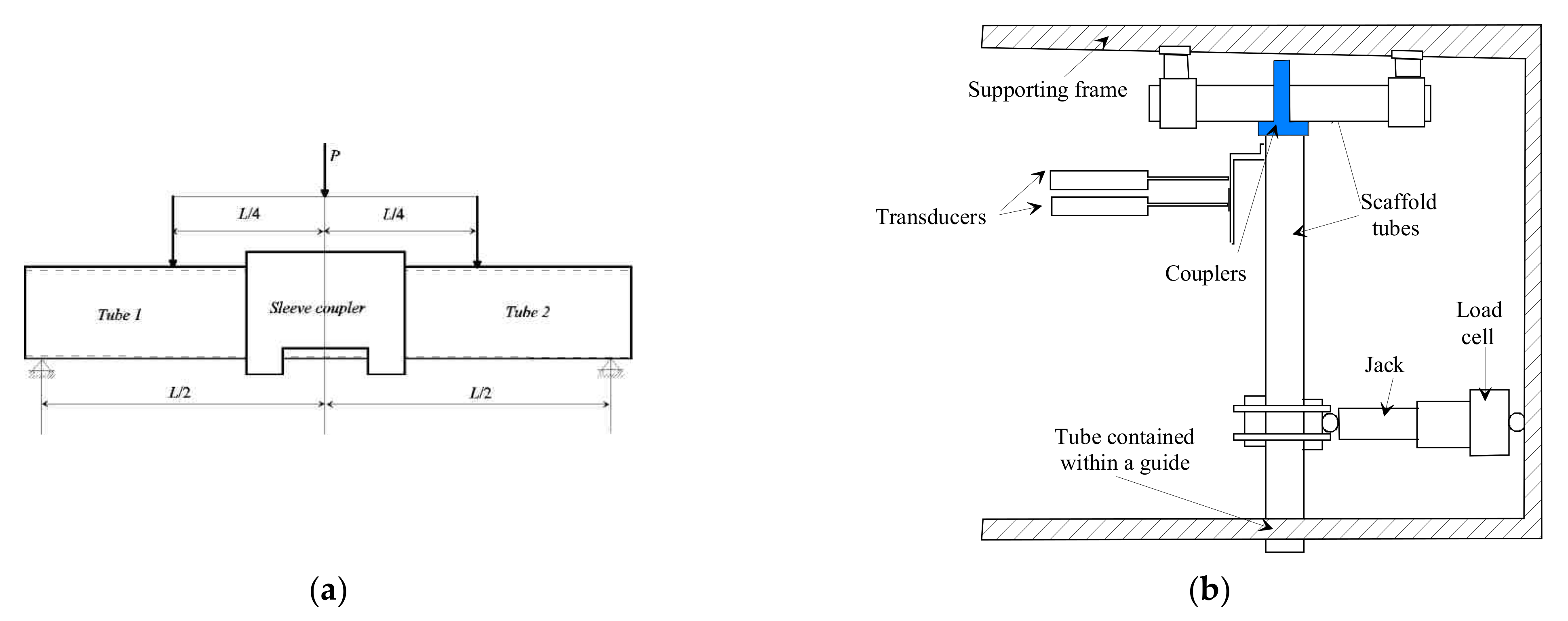
The codes most used in scaffold designs in the UK are BS EN 74.1 [2], BS 5975 [3] and BS EN 12811-1 [4]. These codes require the structural behaviour of the joints to be determined using two standard tests, namely a four-point bending test and a cantilever test. The four-point bending test is used for sleeve connectors and a schematic of the test is shown in Figure 2a. The test procedure commonly used for right-angled and swivel couplers is the cantilever test as shown in Figure 2b. The procedure only determines the stiffnesses and maximum moment that the connection is able to use in one direction. The test procedures do not test the connections in other directions and typically ignore looseness in the connections. Cyclic tests conducted by Abdel-Jaber et al. [1] showed that the mean looseness of sleeve couplers was 0.038 radians, that of right-angled couplers was 0.017 radians and that of swivel couplers was 0.0469 radians. Abdel-Jaber et al. [1] also stated that the existing codes that ignore looseness and stiffness in different directions should be amended to insist on testing the connections in more than one direction. The traditional assumption is that the connections can be considered to be rigid in directions at right angles to the couplers’ direction. For example, a right-angled coupler is often considered only to have a single stiffness in the 90° direction of the connection, and its stiffness in other directions is considered to be rigid. One of the limitations of European codes such as BS EN12811-21 [4] and the UK code BS EN74.1 [2] is that they only consider structural design and do not discuss methods of construction. Hence the UK code BS 5975 [3] is still in use, as it describes modes of construction. Although its original date was of publication was 1982, it has been updated regularly, with the most recent being the version defined in 2016 as it prescribes construction processes.
Following scaffold collapses in the UK, research was undertaken at Oxford University under Lightfoot to determine procedures for scaffold structure analyses, as recorded by Lightfoot et al. [5,6]. Due to the limitations of computer analyses in 1977, Lightfoot and his team developed models of single scaffold tubes based on stability functions. However, when built up into scaffold frames, the numerical analyses produced results that were between 10% and 15% higher than those obtained from experiments.
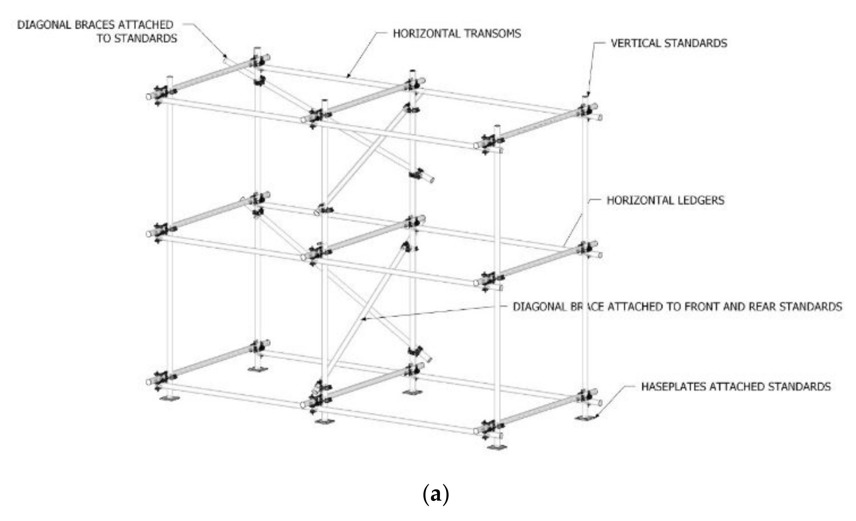
The three types of coupler are designed to enable different types of connection. Firstly, sleeve couplers are used to enable two steel tubes to be joined together so that the tube can be extended in length as seen in Figure 1a. The right-angled coupler is used to join two tubes that are at right-angles to each other so that frame can be built. The joint is shown in Figure 1b. The swivel coupler joins two tubes that are not at right-angles but are used to provide diagonal connections, so that rigidity of the frame is strengthened. Figure 3 shows typical diagonal frames.
Tests conducted at Oxford Polytechnic, now called Oxford Brookes University, in conjunction with Stuttgart University, on the spigot connections used for proprietary scaffolds using the European code BS EN12811-1 [4], showed that the scaffold connections were not rigid but possessed significant looseness. Beale and Godley [7] showed that using a rotational contact element produced good correspondence between the test results and the numerical analysis. The 3D and 2D analyses were undertaken using the Finite Element program LUSAS. As the loads applied to the scaffold structure were horizontal in the same direction, the analyses produced approximately the same answers as shown in Figure 4. Using the traditional models for connections that ignore looseness, it can be seen that the deflections were much smaller than the experimental results. The LUSAS Finite Element program has a rotational element that links two components. The element assumes that no stiffness occurs between the components until rotation occurs and the two components come into contact. The stiffnesses determined by the experiments on the connections were then applied to the connections. The results of the experiments showed that the rotational stiffnesses in the connections used to join standards varied according to the axial loads in the standards. The results had not been commented on before in references [8,9,10]. Most of the research into scaffold structures has concentrated on frames supported by limited tests on the joints, and have usually undertaken monotonic loading until failure. The effects of cyclic loading on scaffolds have not been investigated thoroughly. For example, papers have been published by Chu et al. [11], Chen et al. [12,13] and Peng et al. [14,15] that do not cycle loads but simply load until failure. The most recent research has been conducted by Chandrangsu and Rasmussen [16,17] involving cyclic behaviour. Abdel-Jaber et al. [1,18,19] investigated the effects of cyclical loads on the stiffness of tubular connections, as shown in Figure 2. More details on the history of research into scaffold structures can be found in the review paper by Beale [20] and the book by Beale and André [21].

1.2. Paper Objectives

This paper extends the research into tubular scaffold connections undertaken by the authors Abdel-Jaber et al. [1] into the behaviour of a tubular scaffold system under combinations of variable side loads combined with vertical loads. A test frame was constructed according to the rules as given in BS 5975 [4]. Schematics of the frame are given in Figure 3.
The scaffold was erected within a test frame and horizontal loads were applied cyclically on the left end of the frame, as shown in Figure 5a, and the vertical loads were applied at the top of the frame, as shown in Figure 5b. Although the load was applied non-centrically, the stiffness of the scaffold structure meant that there was no torsional effect. The horizontal loads were applied cyclically to simulate wind loading changing directions, and to show the differences between monotonic and cyclic loading. The vertical loads were applied initially at the middle of a ledger. Note that Figure 5b appears to show that the scaffold structure was not constructed with the ledgers horizontal and the standards vertical. This is purely due to the difficulty of obtaining photographs in the limited space of the test system. Due to the transom bending heavily when loaded vertically, as described below, Figure 5c shows the steel beam used to apply the vertical load to be near the ends of the top transom, to avoid bending the transom as occurred in earlier tests. This procedure was used in tests 4 and 5.
The scaffold system was mounted on baseplates that were not fixed to the bottom of the test rig, so that the scaffold could move horizontally when subjected to side loads, as shown in Figure 6a. At the right-hand end of the frame, there was a barrier to prevent the scaffold system from collapsing beyond the end of the test frame when the horizontal load was applied at the left-hand end. The barrier is shown in Figure 6b. Not fixing scaffold systems into the ground is a common procedure in the UK for small scaffold structures, such as those used for two-storey houses and small buildings. The diagonal braces in the longitudinal direction are shown in Figure 6c and in the transverse direction in Figure 6d. Figure 6c also shows the use of sleeve connectors to extend the length of the frame to 4.0 m. The sleeve connectors were used at each level of the frame. Figure 6a also shows the use of right-angled couplers to join the horizontal ledgers with the vertical standards. They were also used to join the horizontal ledgers with the transoms, as seen in Figure 6c,d. Diagonal braces were also attached between the standards on both sides of the frame, as seen in Figure 6e, which also shows the two levels of the frame.
Displacement measurements were made by attaching Linear Variable Displacement Transducers (LVDTs) to the standards and ledgers as shown in Figure 6a.

2. Material Properties

The test materials consisted of mild steel tubes and the three common connections according to the Chinese specifications for high-strength, low-alloy structural steel metal GB/T/1591-2008 [22]. It is commonly used in the UK for the sleeve, right-angled and swivel couplers as shown in Figure 1. The materials were bought and supplied by a scaffold supplier company. The properties of the connections were documented in the material properties described in the paper by Abdel-Jaber et al. [1]. The scaffold steel tubes were 48.3 mm in diameter with mean thicknesses of 4.0 mm. The scaffold tubes properties were determined by tensile tests. The horizontal ledgers were each 2.0 m long whilst the transoms and diagonal braces were 1.6 m in length. The material properties of the tubes were Young’s modulus of elasticity, 209 GPa and yield strength 392 MPa, and the mean ultimate limit stress (ULS) was 452 MPa. The ULS of the sleeve coupler was 521 MPa.
Using a four-point bending moment test as defined in BS 74.1 [2] and shown in Figure 2a, the initial stiffness of the sleeve couplers in the tests was 18.36 kNm/rad and the second stiffness was 20.18 kNm/rad. The maximum moment the coupler could handle was 5.57 kNm, the maximum rotation was 0.652 rad and the mean looseness was 0.004 rad. It was notable that when the coupler bolts were placed below the tubes being joined that the looseness determined using the cantilever test was 0.025 rad. The cantilever test, as shown in Figure 2b, was used to determine the initial stiffness and capacity of both the right-angled coupler and the swivel-coupler. In both cases the stiffness of the connection in directions at right angles to the two tubes being joined was not rigid, and tests were made to determine correct stiffnesses. For the right-angled couplers in the test series, the maximum moment was 0.5254 kNm, the maximum rotation 0.4169 rad, the initial positive stiffness was 13.9314 kNm/rad and the second stiffness was 0.3998 kNm/rad, and the mean looseness was 0.0165 rad. For the swivel-coupler, the maximum moment was 0.236 kNm, the initial stiffness 6.9807 kNm/rad and the second stiffness 0.2425 kNm/rad. The mean looseness was 0.0447 rad.

3. Test Procedure

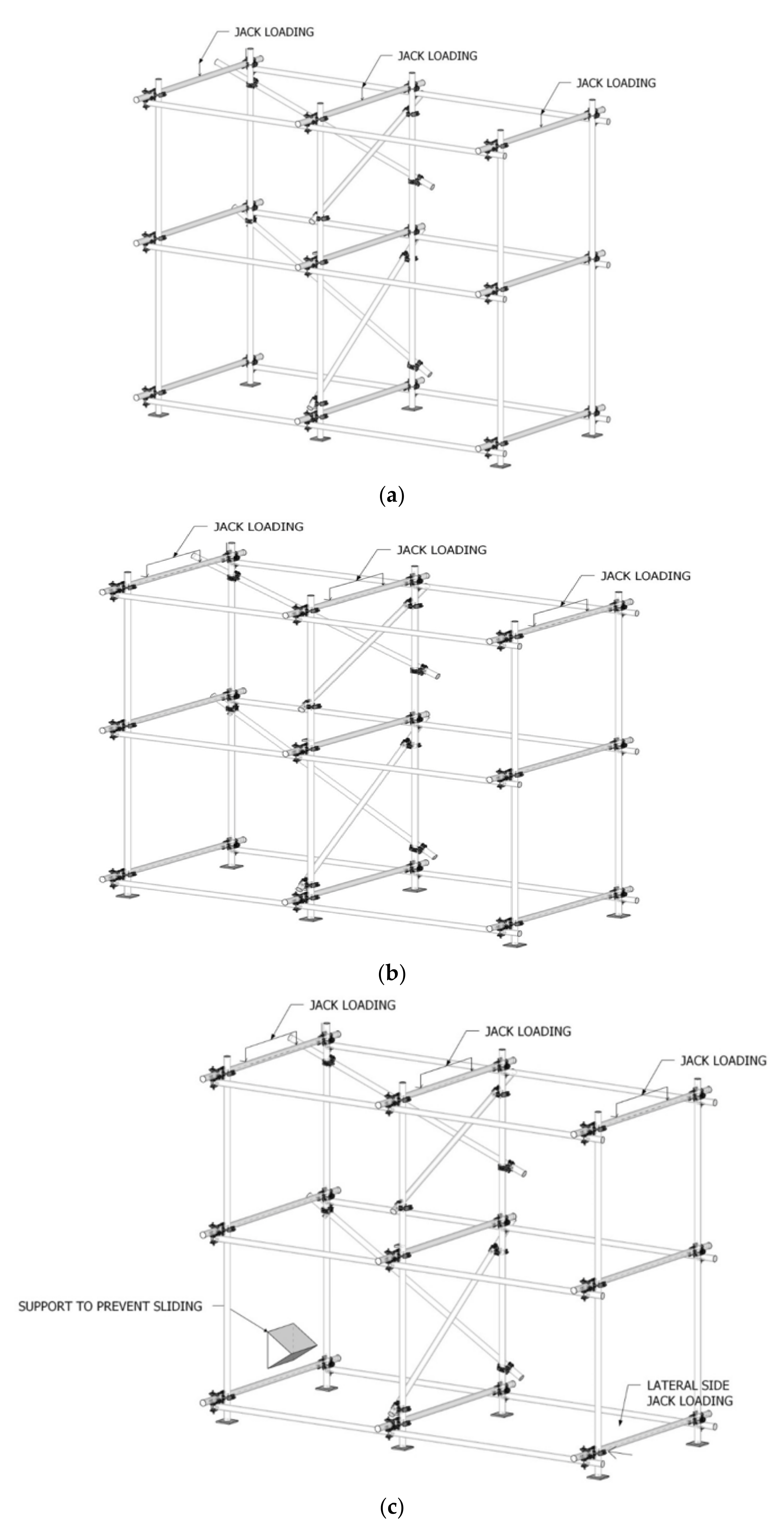
Five tests were undertaken to determine the behaviour of the scaffold under combinations of vertical loads and side loads. In each test, displacements of the frame were measured by 6 LVDTs. An example is shown in Figure 6a. The LVDTs were placed in different positions, depending upon the test. They were always placed horizontally on the two standards supporting the transom subjected to horizontal loads, as shown in Figure 7c. Other positions were horizontally on the middle and on the end standards. At the end of the test frame, away from the horizontal loads, an end plate was attached to ensure that the frame did not go beyond the end of the test rig, as shown in Figure 6b. Schematics of the loading positions are shown in Figure 7. Side loads were always applied at the same end, and in a direction parallel to the main scaffold frame. When cyclic loading was undertaken for horizontal loads, the load was cycled three times, as described in the individual test summaries.
Test 1: Three loading jacks were placed directly at the middle of the top middle transom beams (as shown in Figure 5b and Figure 7a). The jacks had almost the same value of loading. Loading was incrementally increased in the jacks. The transom tube beams loaded by the jacks failed prior to reaching a load of 10 kN in each jack. The test was terminated at this point. The transoms were bent due to high effect of the moment as the load was applied at mid-spans; see Figure 5b. The test was stopped, and new transoms were placed to start the second test. Note that no side loads were applied in this test. Schematics of the tests are given in Figure 7.
Test 2: Three loading jacks were placed on the three steel I-beams on the top of the middle transom tube beams, so as to give concentrated loads on each end of the transom. This was to reduce the amount of the moment on the middle of the transom and allow a higher value of loading capacity; see Figure 7b. The load was incrementally increased in the three jacks, keeping almost the same load value in the transom until failure was observed in the transoms (around 30 kN). As in test 1, no side loads were applied.
Test 3: Side loading was applied, as shown in Figure 5a, in addition to the vertical loading, which was applied in the same way as the vertical loading in test 2. Both loading directions are shown in Figure 7c. The horizontal side loading was applied using one jack applied at the lower part of the frame (left face). Three cycles of loading were applied. The first cycle consisted of a vertical load up to 9 kN, followed by 3 cycles of side loading in the range of (5 kN, −5 kN). In the second cycle of loading, a vertical load up to 14 kN was applied, followed by 3 cycles of side loading in the range of (9 kN, −9 kN). The third cycle of loading consisted of a vertical load up to 20 kN, followed by 3 cycles of side loading in the range of (12 kN, −12 kN). The two standards in the middle were noticed to be buckling elastically, and they recovered their original shape when the test was finished. During the test, the base plate was observed slipping in the direction of the side load. In addition, the base plate rotated in the direction of the supporting standard. When the loads were removed, the side plate returned to its normal rotation, but the end standard did not fully return to its original position. The frame was manually moved to be in the original position.
Test 4: The setup of the vertical loading was arranged in a similar manner to test number 3. In this test, side loading was applied using one jack affecting a lower part of the frame, left rear face, as seen in Figure 5a and Figure 7c. In the first cycle of loading a vertical load of up to 9 kN was applied, followed by 3 cycles of side loading in the range of (4 kN, −4 kN). In the second cycle of loading a vertical load of up to 14 kN was applied, followed by 3 cycles of side loading in the range of (4.5 kN, −4 kN). In the third cycle of loading a vertical load up to 19 kN was applied, followed by 3 cycles of side loading in the range of (4 kN, −4 kN). In the fourth cycle of loading a vertical load up to 20 kN was applied, followed by 3 cycles of side loading in the range of (3 kN, −4.5 kN). The test was terminated at a vertical load of 20.4 kN.
Test 5: The setup of vertical loading was arranged similarly to test number 2. In this test, the side loading was applied using one jack affecting the lower part of the frame’s left rear face, as seen in Figure 5a and Figure 7c. In the first cycle of loading a vertical load of up to 4 kN was applied, followed by 3 cycles of side loading in the range of (1 kN, −4 kN). In the second cycle of loading a vertical load of up to 9.5 kN was applied, followed by 3 cycles of side loading in the range of (3.5 kN, −6 kN). In the third cycle of loading the vertical load was applied up to 14.5 kN, followed by 3 cycles of side loading in the range of (5.5 kN, −9 kN). In the final fourth cycle of loading a vertical load of up to 19 kN was applied, followed by 3 cycles of side loading in the range of (5.5 kN, −9 kN). The test was terminated at a vertical load of 23.6 kN.

4. Test Results

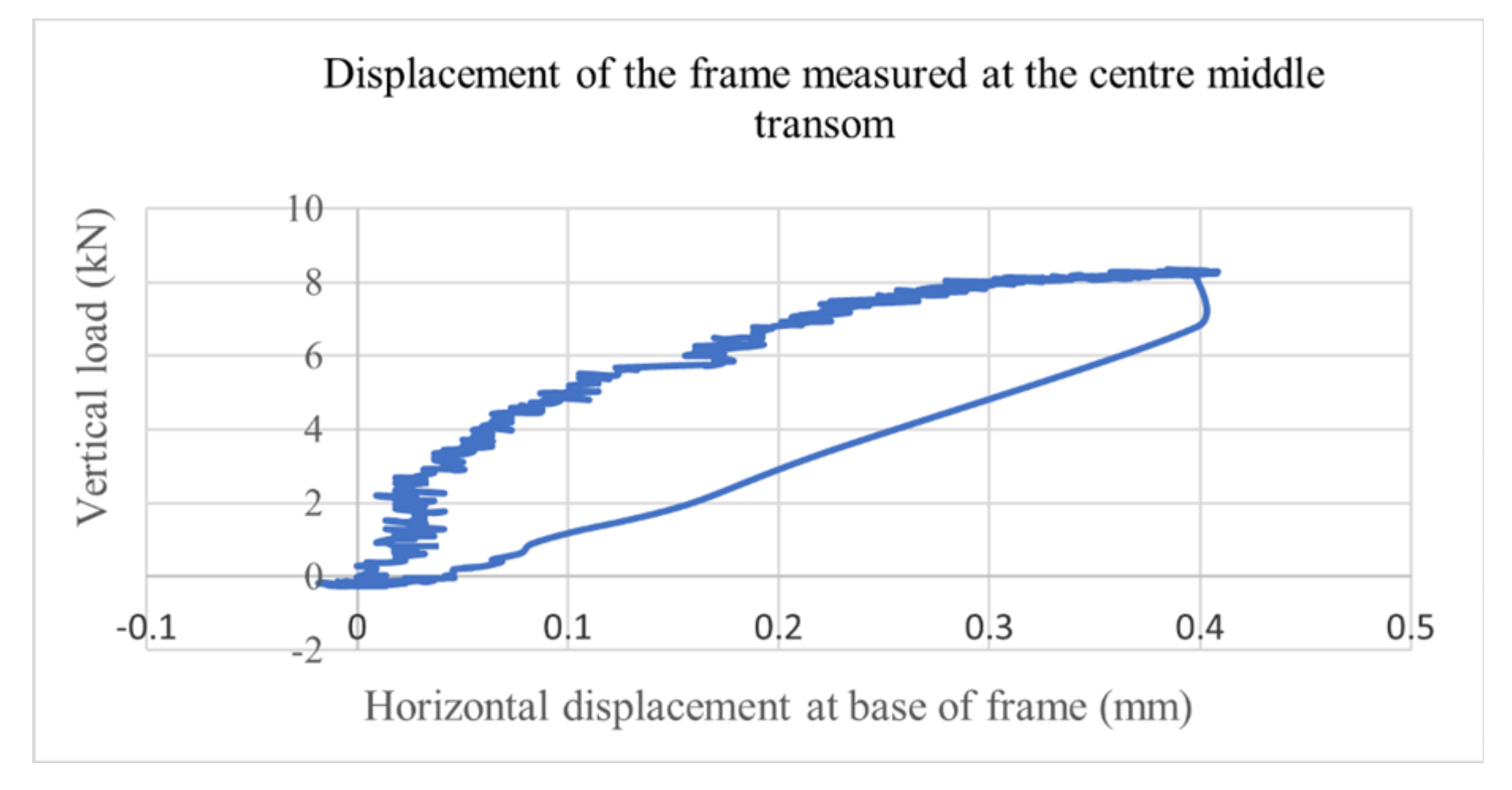
The results of each of the five tests are given below, and comments made for each test. Figure 8, Figure 9, Figure 10, Figure 11 and Figure 12 show the displacements made under the different loadings. The figures of the test results are not smooth, but show the displacements recorded by the LVDTs. The frame did not move smoothly; friction meant that the curves had significant juddering. The authors noted that the tests showed horizontal movement increased with higher horizontal loads, and the frame in each case did not return to the original position. As increased horizontal movement occurred with higher side loads, the authors are confident in the results. The frame had to be returned to the original horizontal position before a subsequent test was performed.
Test 1: The maximum vertical load applied in this test was 8 kN, at which point the transom bent and the test was terminated. As can be seen, the horizontal displacement at the base of the frame was only 0.4 mm. The frame returned to its original horizontal positions, as shown in Figure 8.
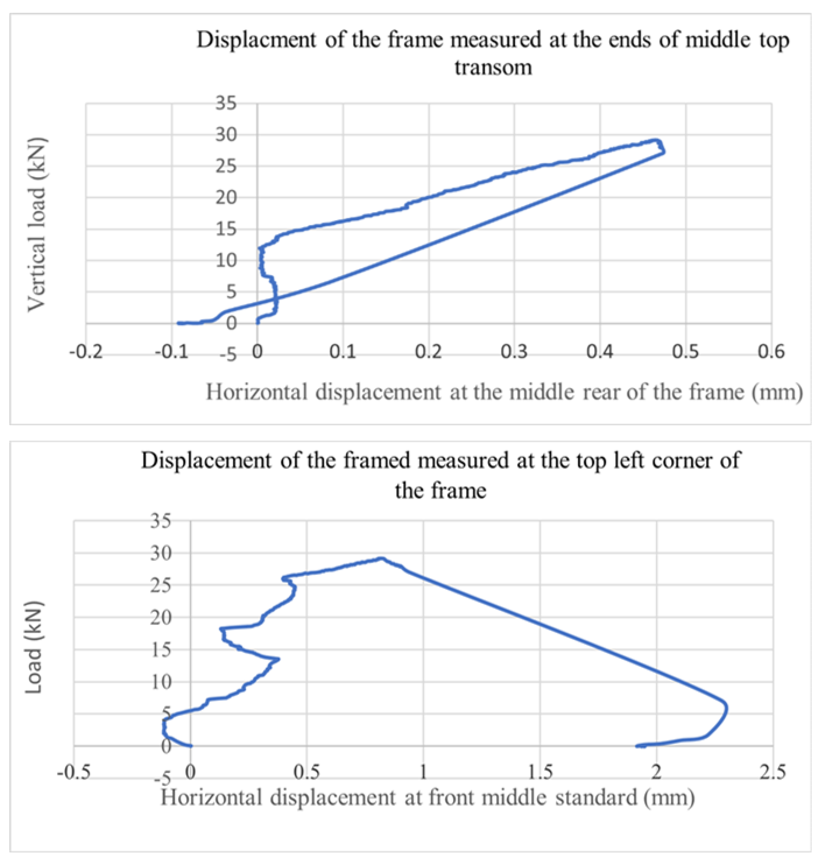
Test 2: The maximum vertical load applied in this test was 30 kN. As can be seen, the horizontal displacement at the base of the frame was only 0.47 mm. At the end of the test, the base standard had a displacement of 0.2 mm from its original position. The frame was repositioned for further tests. It is notable that the frame did not return to its original position. Load/displacement curves are given in Figure 9.
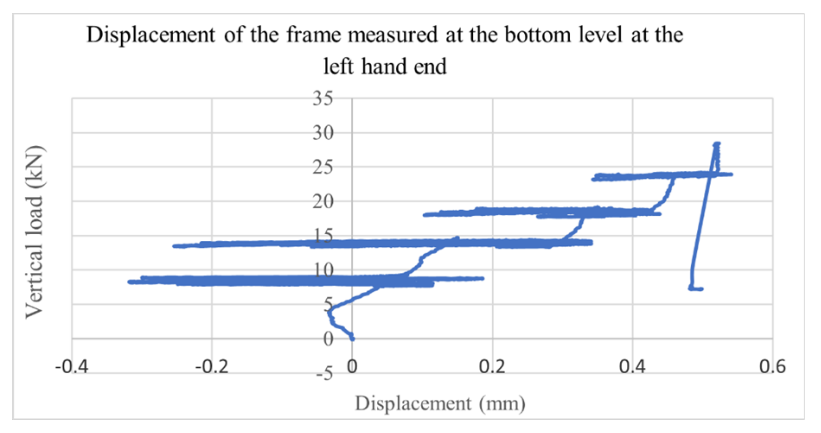
Test 3: The vertical loads were applied cyclically to the top-layer middle transoms of up to 20 kN. It can be clearly seen that the frame did not return to its original position. At the end of the test, the frame had to be returned to the initial position. During the axial loading at the basement, the frame did not move horizontally in a uniform manner, but occasionally ‘jumped’ as shown in Figure 10.
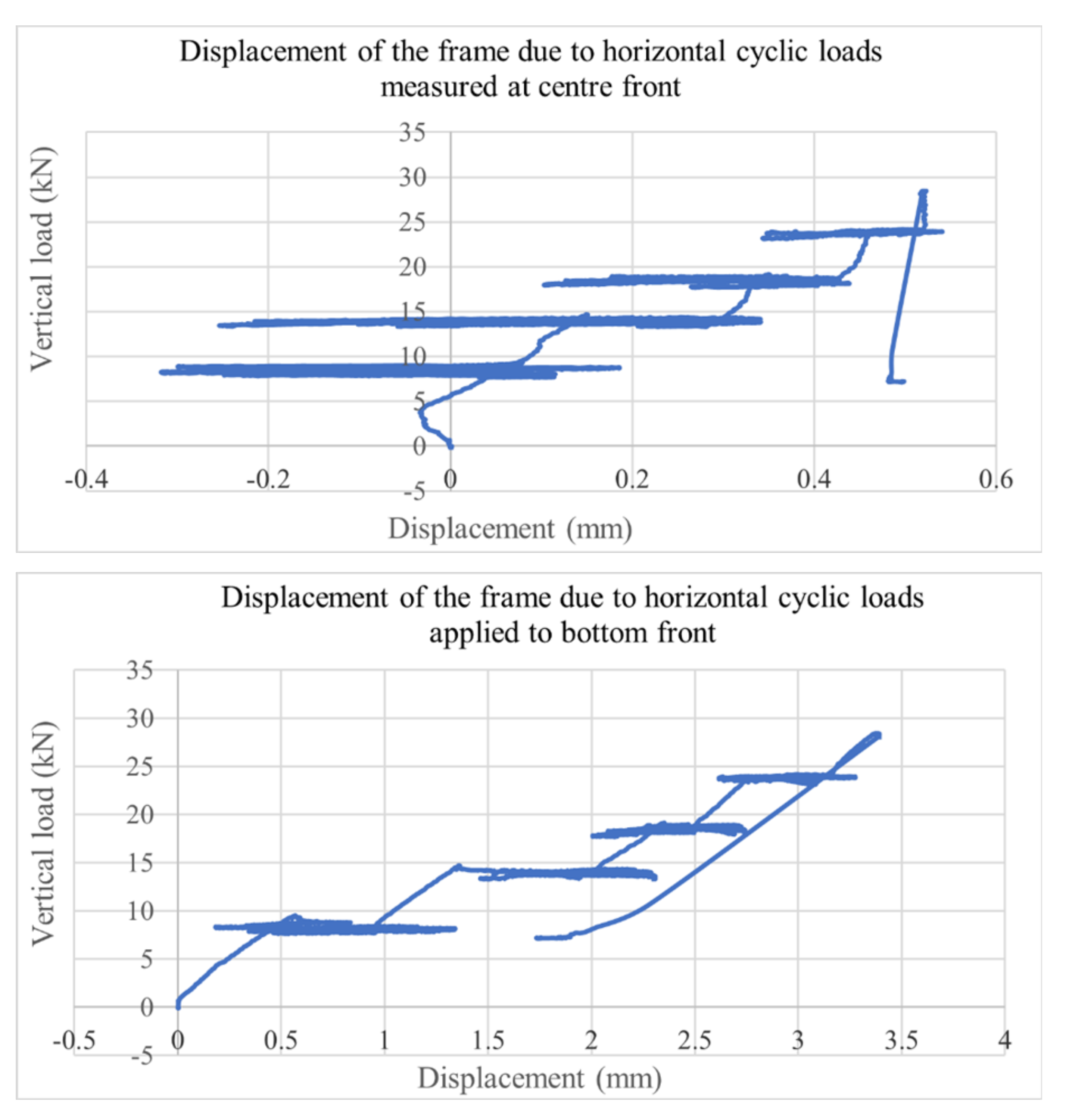
Test 4: The vertical loads were applied to the top-layer middle transoms of up to 28.4 kN. The cyclic horizontal loads were applied from the bottom level, as shown in Figure 5a. The results are given in Figure 11 and illustrate the fact that on reducing the axial load, the frame did not return to zero until the last set. It is notable that on the first and second axial cycles, the frame moved back beyond zero to −0.3 and −0.25 mm.
Test 5: The setup of vertical loading was arranged in a similar manner to test number 2, as described in test 4. In a similar manner to test 4, it can be seen that when the cyclic loads were reduced to zero, the scaffold frame did not return to its original position. The results are given in Figure 12.
The results from the tests are summarised in Table 1.

5. Conclusions

As can be seen from Table 1 it can be seen that the maximum vertical load that could be applied to the scaffold structure was 30 kN in test 2, where beams were used to transfer the vertical load from the middle of the transom to close to the two ends. Applying a horizontal cyclic load sequence meant that the maximum vertical loads had to be reduced so that frame did not distort.
The cyclic loading tests show that scaffolds with the bases not locked into position do not return to their original place when horizontal loads, such as those generated by high winds, occur. This could cause the scaffolds to become distorted and not maintain their design configurations. For small scaffolds, such as those used for one- and two-storey buildings, the effects of wind are smaller and hence the need for the scaffolds to be locked into place is not as important as those required for larger multistory scaffolds. Damage is more likely to occur if material is left on the structures and not fixed in position. For larger structures it is important that the bases are firmly anchored into the ground and the standards for these structures require that the scaffolds have to be tied to the sides of the buildings above the second level.

Author Contributions

Conceptualization, R.G.B.; methodology, M.S.A.-J.; validation, M.A.-J.; formal analysis, M.S.A.-J.; investigation, M.A.-J.; resources, R.G.B.; data curation, M.S.A.-J. and R.G.B.; writing—original draft preparation, M.A.-J., M.S.A.-J. and R.G.B.; writing—review and editing, M.A.-J.; visualization, M.S.A.-J.; supervision, M.S.A.-J. and R.G.B.; project administration, M.A.-J. All authors have read and agreed to the published version of the manuscript.

Funding

This research received no external funding.

Institutional Review Board Statement

Not applicable.

Informed Consent Statement

Informed consent was obtained from all subjects involved in the study.

Data Availability Statement

All data of this research were presented in the article.

Acknowledgments

The authors wish to express their thanks to Oxford Brookes University for enabling the testing to be undertaken.

Conflicts of Interest

The authors declare no conflict of interest.

References

  1. Abdel-Jaber, M.; Abdel-Jaber, M.S.; Beale, R.G.; Allouzi, R.; Shatarat, N.K. Properties of tube and fitting scaffold connections under cyclical loads. J. Constr. Steel Res. 2020, 168, 106008. [Google Scholar] [CrossRef]
  2. BSI. BS EN 74-1, Couplers, Spigot Pins and Baseplates for Use in Falsework and Scaffolds–Part 1: Couplers for Tubes–Requirements and Test Procedures; British Standards Institution: London, UK, 2005. [Google Scholar]
  3. BSI. BS 5975:2008+A1:2011–Code of Practice for Temporary Structures Procedures and the Permissible Stress Design of Falsework, 3rd ed.; British Standards Institution: London, UK, 2014. [Google Scholar]
  4. BSI. EN 12811-1:2003. Temporary Works Equipment, Part 1: Scaffolds-Performance Requirements and General Design; British Standards Institution: London, UK, 2005. [Google Scholar]
  5. Lightfoot, E.; Bhula, D. The idealisation of scaffold couplers for performance tests and scaffold analysis. Mat. Const. 1977, 10, 159–168. [Google Scholar] [CrossRef]
  6. Lightfoot, E.; Olivetto, G. The Collapse Strength of Tubular Steel Scaffold Assemblies. Proceedings. Instution. Civ. Eng. 1977, 63, 311–329. [Google Scholar] [CrossRef]
  7. Beale, R.; Godley, M. The analysis of scaffold structures using LUSAS. In Proceedings of the LUSAS ‘95, Tewkesbury, UK, 3–6 September 1995; pp. 10–24. [Google Scholar]
  8. Beale, R.G.; Godley, M.H.R. Numerical modelling of tube and fitting access scaffold systems. Adv. Steel Constr. 2006, 2, 199–223. [Google Scholar]
  9. Abdel-Jaber, M.S.; Beale, R.G.; Shatarat, N.K.; Shehadeh, M.A. Experimental and theoretical investigation of spigot connections. Adv. Steel Constr. Int. J. 2019, 5, 30–46. [Google Scholar]
  10. André, J.; Beale, R.G.; Baptista, A.M. Experimental and theoretical investigation of Cuplok® Spigot Connections. In Proceedings of the Eighth International Conference on Steel and Aluminium Structures ICSAS 2016, Hong Kong, China, 7–9 December 2016; p. 16. [Google Scholar]
  11. Chu, A.Y.T.; Chan, S.L.; Chung, K.F. Stability of modular steel scaffolding systems—Theory and verification. In Advances in Building Technology; Elsevier: Hong Kong, China, 2002; Volume 1, pp. 621–628. [Google Scholar]
  12. Chen, Y.Y.; Sun, W.; Chan, T.M. Effect of loading protocols on the hysteresis behaviour of structural carbon steel with yield strength up to 460N/mm2. Adv. Struct. Eng. 2013, 16, 707–719. [Google Scholar] [CrossRef]
  13. Chen, Y.Y.; Sun, W.; Chan, T.M. Cyclic stress-strain behaviour of structural steel with yield strength up to 460 N/mm2. Front. Struct. Civ. Eng. 2014, 8, 178–186. [Google Scholar] [CrossRef]
  14. Peng, J.L.; Yen, T.; Pan, A.D.E.; Chen, W.F.; Chan, S.L. Advances in Steel Structures ICASS ’96; Elsevier: Hong Kong, China, 1996; pp. 251–256. [Google Scholar]
  15. Peng, J.; Ho, C.; Lin, C.; Chen, W. Load carrying capacity of single-row steel scaffolds with various setups. Adv. Steel Constr. 2015, 11, 185–210. [Google Scholar]
  16. Chandrangsu, T.; Rasmussen, K. Investigation of geometric imperfections and joint stiffness of support scaffold systems. J. Constr. Steel Res. 2011, 67, 576–584. [Google Scholar] [CrossRef]
  17. Chandrangsu, T.; Rasmussen, K. Structural modelling of support scaffold systems. J. Constr. Steel Res. 2011, 67, 866–875. [Google Scholar] [CrossRef]
  18. Abdel-Jaber, M.; Abdel-Jaber, M.S.; Beale, R.G.; Shatarat, N.K. Cyclic Loading applied to Sleeve Couplers for Tube and Fitting Scaffolds. In ACMS25: Proceedings of the 25th Australasian Conference on Mechanics and Structural Materials (Lecture Notes in Civil Engineering); Springer: Berlin/Heidelberg, Germany, 2019; Volume 37, Chapter 78. [Google Scholar]
  19. Abdel-Jaber, M.S.; Beale, R.G.; Godley, M.H.R.; Abdel-Jaber, M. Rotational Strength and stiffness of Tubular Scaffold Connectors. Proc. Inst. Civ. Eng. Struct. Buil. 2009, 162, 391–403. [Google Scholar] [CrossRef]
  20. Beale, R.G. Scaffold Research–A review. J. Constr. Steel Res. 2014, 98, 188–200. [Google Scholar] [CrossRef] [Green Version]
  21. Beale, R.; André, J. Design Solutions and Innovations in Temporary Structures; IGI Global: Hershey, PA, USA, 2017. [Google Scholar]
  22. GB/T/1591-2008. High Strength Low Alloy Structural Steel; National Standards of the Peoples Republic of China: Taipei, Taiwan, 2009. [Google Scholar]
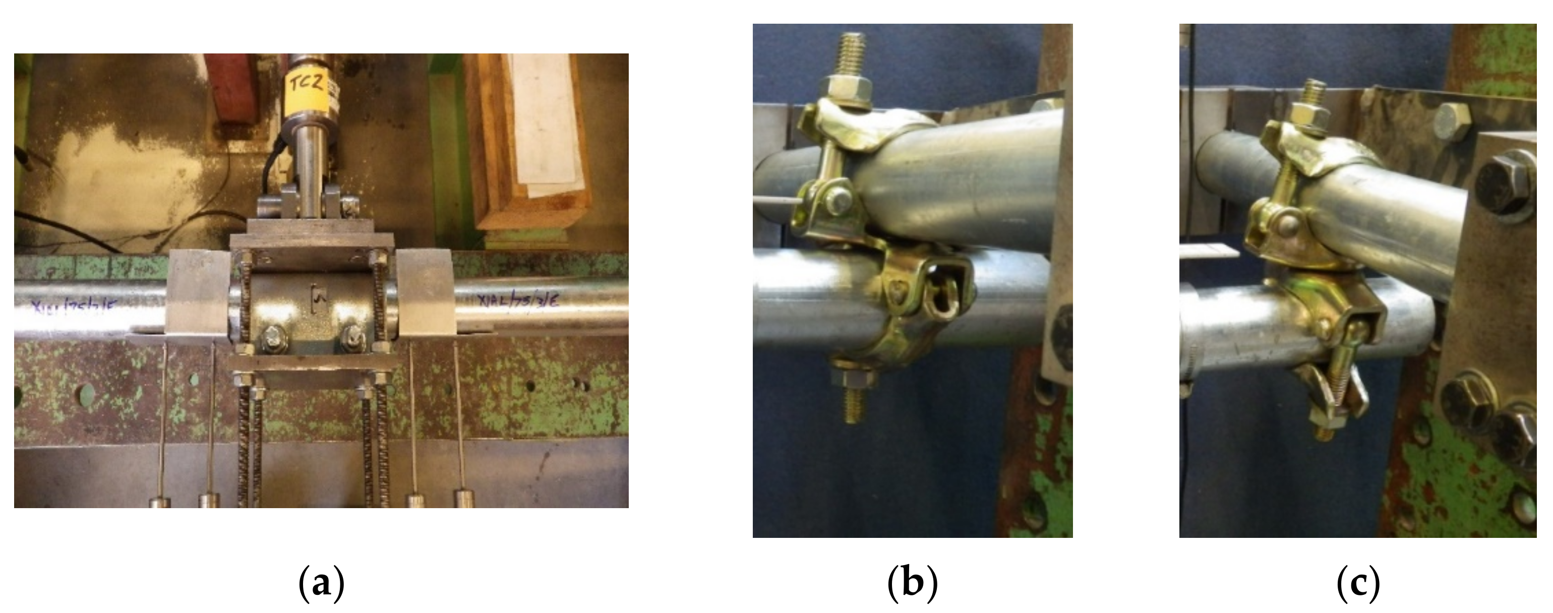
Figure 1. The three connections used in this paper. (a) Sleeve coupler, (b) Right-angled coupler, (c) Swivel coupler.
Metals 12 00040 g001
Figure 2. Schematics of the tests used on couplers. (a) Bending test for sleeve couplers, (b) Cantilever test for right-angled and swivel couplers.
Metals 12 00040 g002
Figure 3. Schematics of test scaffold. (a) Schematic of scaffold frame, (b) Frame dimensions.
Metals 12 00040 g003aMetals 12 00040 g003b
Figure 4. Comparison between different models analysing the deflection of a system scaffold.
Metals 12 00040 g004
Figure 5. Loading procedures for the horizontal and vertical loads. (a) Side loading applied to base of scaffold frame, (b) Vertical loads applied to the top of scaffold frame, (c) Use of a steel beam to prevent bending failure under vertical loading.
Metals 12 00040 g005
Figure 6. Pictures showing the details of the frame. (a) Baseplate at the end of the scaffold frame, (b) End plate at lowest part of frame, (c) Lower part of frame showing diagonal braces with swivel couplers and positions, (d) Diagonal braces attached to middle of frame, (e) Picture of the two levels of the frame.
Metals 12 00040 g006
Figure 7. Schematics showing vertical and lateral load positions. (a) Test (1), (b) Test2, (c) Test 3,4 and 5.
Metals 12 00040 g007
Figure 8. Load displacement curve for Test 1.
Metals 12 00040 g008
Figure 9. Load displacement curves for test 2.
Metals 12 00040 g009
Figure 10. Load displacement curves for test 3.
Metals 12 00040 g010
Figure 11. Load Displacement curves for test 4.
Metals 12 00040 g011aMetals 12 00040 g011b
Figure 12. Load displacement curves for test 5.
Metals 12 00040 g012
Table 1. Load and displacement results from the tests.
Test NumberMaximum Vertical Load (kN) Horizontal Loading (kN)Displacement at End of Test (mm)
110.00.0−0.02 to 0.0
230.00.0−0.20
320.0+12 to −12 (cyclic)0.25
420.4+5.5 to −9.0 (cyclic)−0.3 to −0.25 (different cycles)
522.6+5.0 to −9.0 (cyclic)−0.35 to 0.5 (different cycles)
Publisher’s Note: MDPI stays neutral with regard to jurisdictional claims in published maps and institutional affiliations.