Abstract
Joining of pure copper C1100 and aluminum alloy A6061-T6 plates of 5 mm thickness was investigated. The method was developed by one of the authors, in which the newly created surfaces of a pair of plates obtained by high-speed shear were immediately in contact with a sliding motion with a small overlap length. The total processing time was just about a few milliseconds. To create the new surface, high-speed shaving was also tested. The joining was not possible for the full thickness of the plates. A sharp notch was observed at the joint boundary due to a large shear droop in the copper. Shaving decreased the shear droop, and the joint length through the plate thickness became longer. The joining performance was evaluated by a uniaxial tensile test. The joint efficiency reached 100% using the specimen cut out from the really joined boundary. The affected zone of joining was confirmed by the hardness distribution near the boundary. It was about 30% of the thickness of the plate, which was much smaller than that in welding by heat, and no softened zone was found in both materials.
1. Introduction
The joining of dissimilar metals has been investigated to create a new function in parts, etc. Various metal combinations were tested in welding, bonding and mechanical joining methods. Cold joining methods of the metals by severe plastic deformation have been developed over several decades. Dissimilar metals are usually joined by friction stir welding (FSW) or a laser welding technique.
A wider range of material combinations are provided by FSW, in which the plates are stacked or butted, and the dedicated rotation tool is controlled to move along the path. The evolution of the intermetallic components and the microstructure were investigated in the FSW technique, which has a strong effect on the strength of the joint boundary of dissimilar titanium alloys and that of dissimilar aluminum materials [1,2]. The joining of aluminum to copper has been attractive in electric or battery parts, and it has been investigated [3,4,5]. Further, the addition of Ni at the interface and the coating of the titanium layer on the copper side increased the strength [6,7]. Friction stir “spot” welding technique is also applied to the joining of aluminum, copper and other metals, where the rotating tool stays [8,9]. A simple technique using drilling tool was found to join stainless steel and aluminum [10].
It is well known that time and temperature play important roles in solid-state joining by atomic diffusion at elevated temperatures. On the other hand, under cold conditions, if the surface expansion is relatively large, two metal parts can join at the newly created surface, in which the brittle oxidized surface layer fractures. Cold diffusion bonding is often achieved by very high compressive stress with large plastic deformation. The surface exposure and the pressure affect the welding strength [11]. Diffusion bonding was also tested at high temperatures [12,13,14]. Severe plastic deformation breaks the thin brittle oxide surface layer to press the newly created surface under high pressure. Roll bonding was also tested in addition to press bonding [15]. Hot isotropic pressing (HIP) is also effective for the joining of the different metals [16].
Copper and aluminum were also joined by using a large plastic strain under cold conditions. High compressive deformation, equal channel angular pressing and forging with backward extrusion were investigated [17,18,19,20]. However, the joint efficiency was not 100% even for the small specimen cut off from the welded portion. The wider joined area can be obtained by explosive welding of copper and aluminum plates [21] and combinations of other different metals [22,23]. The use of lasers for the combinations of aluminum and other metals was reviewed [24]. A laser welding technique was investigated for joining copper and aluminum plates. They were stacked, and the laser beam was directed to the copper or aluminum [25,26,27,28,29]. The plates exhibited significant deformation during laser welding, and the change in thickness was large, showing a wavy surface. The method predicting the joint strength was proposed [30]. However, laser welding has the problem of unavoidable changes in the mechanical properties.
Ultrasonic welding with resistance heating achieved the joining of copper and aluminum materials [31]. The materials do not join over the entire contact area. Further, joining the edges cannot be achieved by this method. Mechanical joining is also widely used. Clinching was tested for the stacked copper and aluminum sheets. The addition of adhesive was effective in the process [32]. Joining using a self-piercing rivet is also the preferred option for joining aluminum parts and others, e.g., copper and steel parts. A hybrid joining technique using adhesive was investigated [33].
Joint efficiency was evaluated for the welded interface. However, fracture usually occurs at the interface with the exception of the laser and explosive welding. In diffusion bonding under cold condition, the shape drastically changes from the initial one, and the joining strength depends on the initial surface treatment for the removal of the dirty surface layer. The material softening as a thermal effect arises at the joint boundary in laser welding. The clinching cannot join the plates at their edges. To achieve joining at the edges of the plates, one of the authors devised a novel impact joining method for sheet metal [34], which involved that a pair of sheared surfaces obtained by high-speed shear rub against each other with compressing force under cold conditions. The edge of the sheet is joined to another edge, where the sheet thickness is unchanged. The joining of pure titanium and mild steel plates was thus attained. The base metal of the mild steel fractured in the tensile test [35].
In the present study, the combination of the materials was a pure copper C1100 and an aluminum alloy A6061-T6 plates. To generate a newly created surface for joining them, shearing or shaving was applied. The smaller shear droop was expected in the latter process to increase the flat area in the newly created surface. The main objective is to investigate the effect of the generation method on the joining behavior. Joint efficiency was evaluated, and the joint boundary was also inspected with the energy dispersive X-ray spectrometry. The hardness distribution was measured to check the affected zone of the joining process.
2. Impact Joining Method
An illustration of the impact joining process is shown in Figure 1. The left half is the movable side, which moves downward at a high-speed. On the other hand, the right one is the stationary side. A pair of metallic plates to be joined are simultaneously sheared under high-speed conditions. The material temperature is expected to elevate remarkably, and the material softens in the adiabatic shear-band. The sheared upper plate (Plate 1, left half) continues moving downward, and the sheared surface immediately contacts to the lower sheared surface with a slight overlap length, which is controlled by the dimensions of the tools. The joining process is completed when the sheared upper plate (Plate 1) reaches the prescribed position. The method is a unique joining method that does not require heating. The joining mechanism is diffusion bonding of the newly created surface.
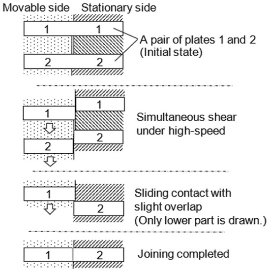
Figure 1.
Impact joining method using sheared surface.
3. Joining Device and Experimental Conditions
The two joining methods were examined, one of which uses the sheared surface. Figure 2 shows the schematic and the photograph of the joining device. It is composed of the rectangular parts, because the structural simplicity is necessary to avoid excessive impulsive stress on the parts, which may cause a catastrophic damage during impact. The joining device is driven by the kinetic energy of the drop weight. The impact velocity was 10 m/s, and the mass was 22 kg. The top edge of Punch 1 is impacted by the drop weight, then the simultaneous shearing of Plates 1 and 2 begins. The illustration of Figure 2a represents the initial state. The left half side, which is the movable side, is supported by a backup plate, under which a circular pipe (A6061, 12 mm outer diameter and 1 mm-thick wall) is placed. The pipe is compressed and exhibits buckling lobes, generating a backup force.
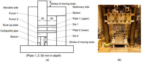
Figure 2.
Impact joining device: (a) Cross-sectional schematic; (b) General view and drop weight.
Figure 3 shows the illustration of the working tools and the plates. The shearing or shaving tools were made with SKD11 tool steel (60 HRC). Die 1 and Punch 2 have a land length of 2 mm. Pre-hardened steel (40 HRC) was chosen for the material of the other parts. The width of the Plate is 50 mm, which corresponds to the length of the joint boundary. In the shear process shown in the Figure 3a, no clearance was set between the shearing tools. To keep the prescribed overlap length, two small rubber spacers were inserted between Punch 2 and Die 1 only at both ends. Hence, the joining was not completed near both edges of the joint boundary.
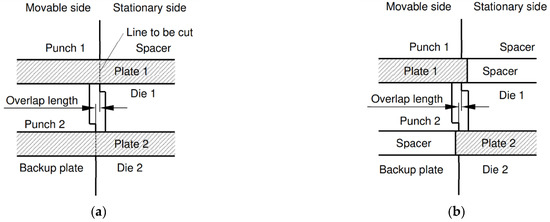
Figure 3.
Detail of working tools: (a) Joining using sheared surface; (b) Joining using shaved surface.
Further, the joining test of dissimilar materials was examined for the shaved surfaces. In the shaving of the plates, the right side of Plate 1 and the left side of Plate 2 in Figure 3a are replaced by the spacers with the same thickness. The width of the plate was 31 or 30.5 mm. The shaving allowance of the upper plate was 1.0 or 0.5 mm, and that of the lower plate was reduced by the overlap length. The mechanical properties of the test material are listed in Table 1. The materials were a pure copper C1100-1/4H and an aluminum alloy A6061-T6. The thickness of the plates was 5.0 mm. In the joining test using the sheared surface, the similar metal and the dissimilar ones were combined. The dissimilar metals were combined in the joining test using the shaved surface.

Table 1.
Mechanical properties of test materials (Thickness 5 mm).
4. Experimental Result and Discussions
4.1. Joining Using Sheared Surface
The examples of the joined plates are shown in Figure 4 for similar and dissimilar combinations of the materials. In these cases, the impact speed of the drop weight was 10 m/s, and the overlap length was 0.3 mm. The rubber spacer, whose color is black, is seen at the ends of the boundary. It was dragged into the boundary during the joining process. Figure 5 shows the cross-section of the joint boundary for the cases of Figure 4. The weld mismatch was caused by the vibration and the dimensional error of the stopper in the joining device. The device will be improved in future study. Gaps are observed near the plate surface. They are large in the combination of C1100 and C1100, because the shear droop of C1100 is larger than that of A6061 due to the fact that the strain hardening exponent of C1100 is greater than that of A6061.

Figure 4.
General view of joined specimen: (a) C1100-C1100; (b) A6061-A6061; (c) C1100-A6061.

Figure 5.
Cross-section of joint boundary using sheared surface: (a) C1100-C1100, Contact length: 1.7 mm; (b) A6061-A6061, 3.3 mm; (c) C1100-A6061, 2.5 mm.
In the joining of dissimilar materials, the softened aluminum by the shear deformation is squeezed out, though the copper is not. A6061 is harder than C1100 at room temperature. However, it becomes softer than C1100 when the temperature elevates by the large deformation under impact; hence, the aluminum was squeezed out.
The joint efficiency was defined by the following equation.
The tensile test was performed. The width of the specimen was 10 mm. It was machined out from the central portion, and the force was loaded in the direction vertical to the joint boundary. The joint efficiency is shown in Figure 6. It was roughly evaluated for the full thickness (5 mm) and the observed contact lengths of 1.7, 3.3 or 2.5 mm. Even for the contact length, the joint efficiency is low. This implies that the contact length is not the actual joined length similar to the ultrasonic welding [31]. The notch effect also weakens the strength due to the stress concentration at the tip of the gap opening. In addition, the joining condition is not uniform over the boundary. Increasing the test sample may yield more accurate results, though the obtained result is reasonable.
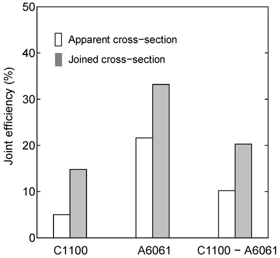
Figure 6.
Joint efficiency of three different combinations.
With respect to the joining of C1100 and A6061, the joint efficiency calculated with a contact length of 2.5 mm is about 20%. Therefore, the actual joint length is much shorter than the contact length. When the notch effect was ignored, the calculated joint length is only about 0.5 mm.
The tensile test specimen with 4 mm width was machined out from the joined plate. The tensile speed was as low as 0.1 mm/s to avoid the speed effect on the deformation behavior, and eight specimens were used for each condition. Figure 7 shows the fracture strength and joint efficiency of the joining of C1100 and A6061 evaluated for the overlap lengths of 0.1, 0.3, 0.5 and 0.7 mm. The average fracture strength and the joint efficiency are also given in the figure. In the case of the 0.1 mm overlap length, the joint efficiency is very low or zero. It is about 30% for the case of 0.3 or 0.5 mm. It is almost zero for 0.7 mm. The suitable overlap length was determined to be 0.3 mm considering the average value of the joint efficiency.
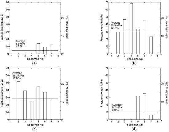
Figure 7.
Fracture strength and joint efficiency in joining of C1100 and A6061 for various overlap lengths: (a) 0.1 mm; (b) 0.3 mm; (c) 0.5 mm; (d) 0.7 mm.
An example of fractured boundary is shown in Figure 8, which was separated by bending. The actually joined zone exhibits the gray surface. The shape of these zones is mirror symmetrical, as clearly observed in the magnified photograph. The joined part is a band with of about 1 mm width, which is about 0.7 mm apart from the center of the thickness. Considering the calculated joint length of 0.5 mm, the small tensile specimen with 0.5 mm thickness shown in Figure 9 was cut out from the band using a wire discharge cutting machine (Mitsubishi Electric Ltd., Japan).

Figure 8.
Example of joint boundary separated by bending (upper: C1100, lower: A6061, overlap length: 0.3 mm): (a) General view; (b) Magnified view.

Figure 9.
Schematic of tensile test specimen joined using sheared surface.
The joint efficiency is shown in Figure 10. The average is as high as about 80%. The fractured specimens are shown in Figure 11. It should be noted that the No. 3 specimen fractured at the material of C1100 exhibit a diffuse necking. However, the joint efficiency is 95%. This is because the ultimate tensile strength of the material was evaluated for the original thickness of 5 mm, which was 10-times thicker than the thickness of the specimen. It is well known that the strength depends on the thickness, where it weakens as the thickness decreases [36]. Further, the surface of the small specimen is rougher than the cold-rolled original plate, because the specimen was made using a wire discharge cutting machine.
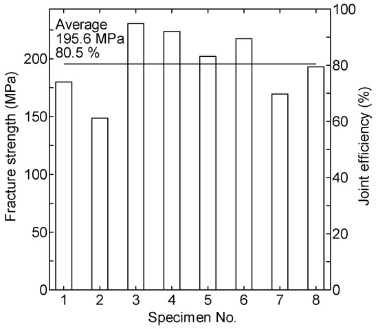
Figure 10.
Fracture strength and joint efficiency evaluated for adhesion part (overlap length: 0.3 mm).

Figure 11.
Fractured tensile test specimen joined using sheared surface: (a) Fracture at base metal of copper C1100; (b) Fracture at joint boundary.
The joint boundary was analyzed using the scanning electron microscopy (JEOL Ltd., Tokyo, Japan) with energy dispersive X-ray analysis (SEM-EDX) as shown in Figure 12. A thin layer whose contrast differs from those of the copper and aluminum is observed, and it is clearer in the magnified photograph. The boundary shows an irregular wavy pattern. The intensity of the aluminum with a blue line and that of the copper with a green one cross at the boundary. The intermetallic phase was not inspected at present. The temperature could not be measured, because the processing time is only a few milliseconds. Heterogeneous mixtures of Al and Cu possibly result in their intermetallic phase found in the friction stir welding of similar metals [3].

Figure 12.
SEM-EDX analysis of joint boundary (left: C1100, right: A6061): (a) SEM image and line scan result; (b) Magnified view of central part.
4.2. Joining Using Shaved Surface
The joining of C1100 and A6061 was investigated. An example of the joined plates is shown in Figure 13. The cross-sections are shown in Figure 14 for two different overlap lengths. Comparing these cross-sectional profiles with those in Figure 5c, the shear droop is almost prevented. The contact length in the thickness direction of the plate is about 4 mm, which is longer than that in Figure 5c, though the gap opening is observed near both surfaces. The tensile test specimen shown in Figure 15 was made using a wire discharge cutting machine. The thickness is 2 mm, which is half of the contact length. This length is expected to be the actual joining length. This estimation may be reasonable because the undulation of the boundary is also small in Figure 14 compared with that in Figure 5c.
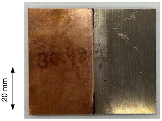
Figure 13.
Joined specimen using shaved face (left: C1100, right: A6061, shaving allowance: C1100 1.0 mm, A6061 0.9 mm, overlap length: 0.1 mm).
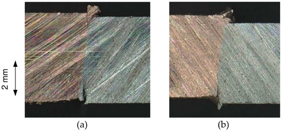
Figure 14.
Cross-section of joint boundary using shaved surface: (a) Shaving allowance: C1100 1.0 mm, A6061 0.9 mm, overlap length: 0.1 mm; (b) Shaving allowance: C1100 1.0 mm, A6061 0.7 mm, overlap length: 0.3 mm.

Figure 15.
Tensile test specimen joined using shaved surface: (a) Schematic; (b) Photograph.
Figure 16 shows the joint efficiency for the three experimental conditions. The shaving allowance of A6061 is smaller than that of C1100 by the overlap length, as mentioned above. When the overlap length is 0.1 mm, the number of tests was increased. This is because the experiment was started in this condition, and the dispersion was also roughly checked. Examples of the fractured specimen are shown in Figure 17. Diffuse necking often occurs at the C1100 part, where the joint boundary is not damaged. A joint efficiency of 100% was achieved for the setting with overlap lengths of 0.1 or 0.3 mm. The possibility of perfect joining seems higher when the overlap length is set to be 0.3 mm.
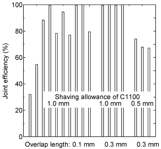
Figure 16.
Joint efficiency of joining using shaved surface under various experimental conditions.

Figure 17.
Fractured tensile test specimen joined using shaved surface: (a) Fracture at joint boundary; (b) Fracture at C1100 part.
It is worthwhile to confirm the affected zone by the joining. Micro Vickers’ hardness was measured near the joint boundary. Figure 18 shows the distribution of the hardness for both materials. The hardness clearly increases as the measurement position is closer to the joint boundary. The affected zone due to the joining process is about 1.5 mm, which is quite small compared with the thickness of the plate. The increase in hardening is higher in C1100, because its strain hardening exponent or n-value is larger than that of A6061. The difference due to experimental condition is not observed. There is no softening region. This is a significant advantage of this joining method, because the A6061-T6 material does not weaken near the joint boundary.
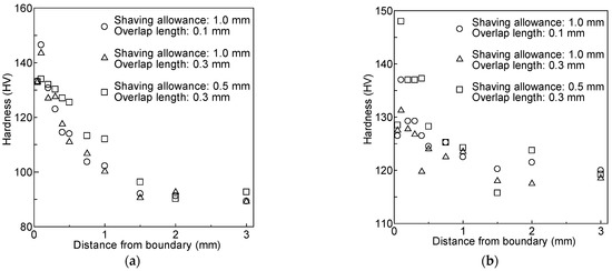
Figure 18.
Distribution of Vickers’ hardness HV: (a) C1100; (b) A6061.
The strain distributions along the central line of the tensile specimen are shown in Figure 19, which were measured at the maximum load point using a digital image correlation (DIC) measurement system (GOM correlate V8 SR1, GOM, Germany). The thickness strain was calculated using the measured longitudinal and transverse strains by assuming a constant volume. The strain of A6061 is not exactly zero, but near zero, in both cases. It includes the measurement error to some extent. On the other hand, the strain of C1100 increases as the measurement point moves away from the boundary. The error is relatively larger in the thickness strain, because the error in the plane directions is accumulated. However, the trend is plausible, and the strain change through the boundary is smooth.
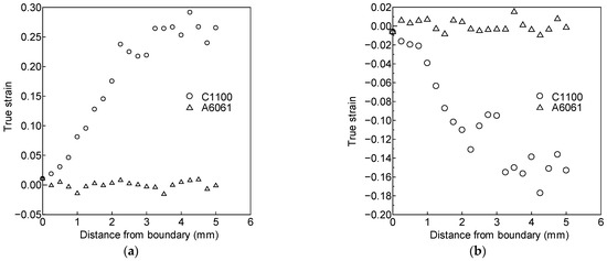
Figure 19.
Strain distribution at maximum load point: (a) Longitudinal direction; (b) Thickness direction.
5. Conclusions
Impact joining at the edges of a pure copper C1100 and an aluminum alloy A6061 plates was carried out. Two different methods of generating newly created surfaces were examined. The joining was not performed through the full thickness of the plate, where the notches were observed at the plate surface. The joining test using the sheared surface exhibited the 100% joint efficiency, where the 0.5 mm thick tensile specimen machined out from the 5 mm thick joined plate was used. When the new surface was created by shaving, the shear droop in C1100 was successfully decreased, by which the contact length at the boundary was increased. The joint efficiency was 100% for the 2 mm thick specimens. The measurement of the hardness revealed that the affected zone by the joining process was quite narrow. It was only about 30% of the thickness of the plate, and no weakened zone was observed in A6061-T6. This is a significant advantage of this joining method. The strain distribution was continuous through the joint boundary.
Author Contributions
Idea proposal, methodology, investigation, writing, M.Y.; methodology, investigation, T.I., H.T., M.N.; All authors have read and agreed to the published version of the manuscript.
Funding
No external funding.
Data Availability Statement
Available from the corresponding author (M.Y.) upon request.
Conflicts of Interest
The authors declare no conflict of interest.
References
- Senoris-Puentes, S.; Serrano, R.F.; Gonzalez-Doncel, G.; Hattel, J.H.; Mishin, O.V. Microstructure and mechanical properties of friction stir welded AA6061/AA6061 + 40 vol% SiC plates. Metals 2021, 11, 206. [Google Scholar] [CrossRef]
- Ji, Y.; Wu, S.; Zhao, D. Microstructure and mechanical properties of friction welding joints with dissimilar titanium alloys. Metals 2016, 6, 108. [Google Scholar] [CrossRef]
- Ouyang, J.; Yarrapareddy, E.; Kovacevic, R. Microstructural evolution in the friction stir welded 6061 aluminum alloy (T6-temper condition) to copper. J. Mater. Proc. Technol. 2006, 172, 110–122. [Google Scholar] [CrossRef]
- Zhu, X.; Fan, Y.; Xie, L.; Xiao, X.; Wang, P.; Yang, S.; Jiang, C. Effect of rotation speed on microstructure and mechanical properties of continuous drive friction welded dissimilar joints of 6061-T6 Al and copper. Metals 2022, 12, 1173. [Google Scholar] [CrossRef]
- Prakash, O.; Dwivedi, S.; Pagrut, S.; Rajawat, M.S.; Raj, R.; Srivastava, A.K.; Dixit, A.R. Investigation on the friction stir assisted lap joining of pure copper and aluminium 6063 alloy. Mater. Today Proc. 2022, 62, 398–403. [Google Scholar] [CrossRef]
- Kurabayashi, K.; Tokita, S.; Sato, Y. Effect of Ni addition on the interfacial strength of Al/Cu dissimilar welds produced by friction stir lap welding. Metals 2022, 12, 453. [Google Scholar] [CrossRef]
- Eslami, N.; Hischer, Y.; Harms, A.; Lauterbach, D.; Bohm, S. Influence of copper-sided tin coating on the weldability and formation of friction stir welded aluminum-copper-joints. Metals 2019, 9, 179. [Google Scholar] [CrossRef]
- Bergmann, J.P.; Petzoldt, F.; Schurer, R.; Schneider, S. Solid-state welding of aluminum to copper—Case studies. Weld. World 2013, 57, 541–550. [Google Scholar] [CrossRef]
- Gao, K.; Zhang, S.; Mondal, M.; Basak, S.; Hong, S.T.; Shim, H. Friction stir spot butt welding of dissimilar S45C steel and 6061-T6 aluminum alloy. Metals 2021, 11, 1252. [Google Scholar] [CrossRef]
- Dehghan, S.; Abbasi, R.; Baharudin, B.T.H.T.; Mousavi, M.L.; Soury, E. A novel approach to friction drilling process: Experimental and numerical study on friction drill joining of dissimilar materials AISI304/AL6061. Metals 2022, 12, 920. [Google Scholar] [CrossRef]
- Bay, N. Mechanisms producing metallic bonds in cold welding. Weld. Res. Suppl. 1983, 62, 137–142. [Google Scholar]
- Shirzadi, A.A.; Zhang, C.; Mughal, M.Z.; Xia, P. Challenges and latest developments in diffusion bonding of high-magnesium aluminium alloy (Al-5056/Al-5A06) to stainless steels. Metals 2022, 12, 1193. [Google Scholar] [CrossRef]
- Silva, M., Jr.; Ramos, A.S.; Simoes, S. Joining Ti6Al4V to alumina by diffusion bonding using titanium interlayers. Metals 2021, 11, 1728. [Google Scholar] [CrossRef]
- Huang, Z.; Yanagimoto, J. Dissimilar joining of aluminum alloy and stainless steel thin sheets by thermally assisted plastic deformation. J. Mater. Proc. Technol. 2015, 225, 393–404. [Google Scholar] [CrossRef]
- Wu, H.Y.; Lee, S.; Wang, J.Y. Solid-state bonding of iron-based alloys, steel-brass, and aluminum alloys. J. Mater. Proc. Technol. 1998, 75, 173–179. [Google Scholar] [CrossRef]
- Loh, N.L.; Wu, Y.L.; Khor, K.A. Shear bond strength of nickel/alumina interfaces diffusion bonded by HIP. J. Mater. Proc. Technol. 1993, 37, 711–721. [Google Scholar] [CrossRef]
- Pawlicki, M.; Drenger, T.; Pieszak, M.; Borowski, J. Cold upset forging joining of ultra-fine-grained aluminium and copper. J. Mater. Proc. Technol. 2015, 223, 193–202. [Google Scholar] [CrossRef]
- Eivani, A.R.; Mirzakoochakshirazi, H.R.; Jafarian, H.R. Investigation of joint interface and cracking mechanism of thick cladding of copper on aluminum by equal channel angular pressing (ECAP). J. Mater. Res. Technol. 2020, 9, 3394–3405. [Google Scholar] [CrossRef]
- Matsumoto, R.; Hashimoto, K.; Utsunomiya, H. Improvement in bonding strength by applying circumferential sliding in cold copper/aluminum forge-bonding. J. Mater. Proc. Technol. 2022, 307, 117685. [Google Scholar] [CrossRef]
- Lapovok, R.; Dubrovsky, M.; Kosinova, A.; Raab, G. Effect of severe plastic deformation on the conductivity and strength of copper-clad aluminium conductors. Metals 2019, 9, 960. [Google Scholar] [CrossRef]
- Wang, Q.; Li, X.; Shi, B.; Wu, Y. Experimental and numerical studies on preparation of thin AZ31B/AA5052 composite plates using improved explosive welding technique. Metals 2020, 10, 1023. [Google Scholar] [CrossRef]
- Kaya, Y. Investigation of copper-aluminium composite materials produced by explosive welding. Metals 2018, 8, 780. [Google Scholar] [CrossRef]
- Zhao, H. The microstructure and property of a titanium-carbon steel clad plate prepared using explosive welding. Metals 2022, 12, 129. [Google Scholar] [CrossRef]
- Bunaziv, I.; Akselsen, M.; Ren, X.; Nyhus, B.; Eriksson, M.; Gulbrandsen-Dahl, S. Review on laser-assisted joining of aluminium alloys to other metals. Metals 2021, 11, 1680. [Google Scholar] [CrossRef]
- Seibold, M.; Schricker, K.; Bergmann, J.P. Systematic adjustment of the joining time in pulsed laser beam welding of aluminum-copper joints by means of a closed-loop control. J. Adv. Join. Process. 2022, 5, 100104. [Google Scholar] [CrossRef]
- Zhang, Y.; Li, Y.; Luo, Z.; Yuan, T.; Bi, J.; Wang, Z.M.; Wang, Z.P.; Chao, Y.J. Feasibility study of dissimilar joining of aluminum alloy 5052 to pure copper via thermo-compensated resistance spot welding. Mater. Des. 2016, 106, 235–246. [Google Scholar] [CrossRef]
- Mathivanan, K.; Plapper, P. Laser welding of dissimilar copper and aluminum sheets by shaping the laser pulses. Procedia Manufact. 2019, 36, 154–162. [Google Scholar] [CrossRef]
- Dimatteo, V.; Ascari, A.; Liverani, E.; Fortunato, A. Experimental investigation on the effect of spot diameter on continuous-wave laser welding of copper and aluminum thin sheets for battery manufacturing. Opt. Laser Technol. 2022, 145, 107495. [Google Scholar] [CrossRef]
- Dimatteo, V.; Ascari, A.; Fortunato, A. Continuous laser welding with spatial beam oscillation of dissimilar thin sheet materials (Al-Cu and Cu-Al): Process optimization and characterization. J. Manuf. Process. 2019, 44, 158–165. [Google Scholar] [CrossRef]
- Mathivanan, K.; Plapper, P. Artificial neural network to predict the weld status in laser welding of copper to aluminum. Procedia CIRP 2021, 103, 61–66. [Google Scholar] [CrossRef]
- Yang, J.; Cao, B. Investigation of resistance heat assisted ultrasonic welding of 6061 aluminum alloys to pure copper. Mater. Des. 2015, 74, 19–24. [Google Scholar] [CrossRef]
- He, X.; Zhao, L.; Deng, C.; Xing, B.; Gu, F.; Ball, A. Self-piercing riveting of similar and dissimilar metal sheets of aluminum alloy and copper alloy. Mater. Des. 2015, 65, 923–933. [Google Scholar] [CrossRef]
- Lei, L.; He, X.; Zhao, D.; Zhang, Y.; Gu, F.; Ball, A. Clinch-bonded hybrid joining for similar and dissimilar copper alloy, aluminium alloy and galvanised steel sheets. Thin-Walled Struct. 2018, 131, 393–403. [Google Scholar] [CrossRef]
- Yamashita, M.; Tezuka, T.; Hattori, T. Joining experiment of aluminum sheets using high-speed shearing. Appl. Mech. Mater. 2014, 566, 379–384. [Google Scholar] [CrossRef]
- Yamashita, M.; Shibuya, T.; Nikawa, M. Impact joining of metallic sheets and evaluation of its performance. Mater. Res. Proc. 2019, 13, 91–96. [Google Scholar] [CrossRef]
- Hou, Y.; Mi, X.; Xie, H.; Zhang, W.; Huang, G.; Peng, L.; Feng, X.; Yang, Z. Size effect on mechanical properties and deformation behavior of pure copper wires considering free surface grains. Materials 2020, 13, 4563. [Google Scholar] [CrossRef]
Publisher’s Note: MDPI stays neutral with regard to jurisdictional claims in published maps and institutional affiliations. |
© 2022 by the authors. Licensee MDPI, Basel, Switzerland. This article is an open access article distributed under the terms and conditions of the Creative Commons Attribution (CC BY) license (https://creativecommons.org/licenses/by/4.0/).