Article

In Situ Alloying of Fe-Cr-Co Permanent Magnet by Selective Laser Melting of Elemental Iron, Chromium and Cobalt Mixed Powders

1
Central Iron & Steel Research Institute, Beijing 100081, China
2
Material Digital R&D Center, China Iron & Steel Research Institute Group, Beijing 100081, China
*
Author to whom correspondence should be addressed.
Metals 2022, 12(10), 1634; https://doi.org/10.3390/met12101634
Submission received: 3 September 2022 / Revised: 26 September 2022 / Accepted: 26 September 2022 / Published: 29 September 2022

Abstract

:
Fe-25Cr-15Co (wt.%) permanent magnets were fabricated via selective laser melting (SLM) and in situ alloying from a blend of Fe, Cr and Co elemental powders. Under the optimal laser scanning process, the as-built Fe-25Cr-15Co alloy has a homogeneous composition distribution without defects such as holes or un-melted particles, and presents a single α phase with the bcc crystal structure. The density of as-built samples was 7.705 g/cm3 (the relative density is 99.32%). The preferred magnetic properties of the sample in the isotropic state were obtained as Hc = 22.84 kA/m, Br = 0.86 T and (BH)max = 7.98 kJ/m3. The hardness and yield strength of Fe-25Cr-15Co permanent magnets are above 331.5 HV and 800 MPa, respectively. The results of this study verified the feasibility of fabricating Fe-Cr-Co permanent magnets by SLM in situ alloying and can be extended to a wide range of applications that require complex shapes with variable magnetic circuit characteristics or gradient structures.

1. Introduction

Fe-Cr-Co permanent magnet alloys have attracted more and more attention in recent years owing to their outstanding mechanical properties, ductility, wide working temperature range and modest magnetic properties [1,2]. Consequently, they have been widely used in telephone receivers, magnetic sensors, wind turbines, aircraft magnetos and hysteresis motors [3,4].
The desired magnetic properties of Fe-Cr-Co magnets are induced by the spinodal decomposition of the supersaturated solid solution α phase into an Fe-Co-rich ferromagnetic phase, the so-called α1, and a paramagnetic phase (α2) enriched with Cr. The magnetic properties are affected by the aspect ratio, interconnection, size, orientation and volume fraction of spinodal phases [5]. The heat-treatment (HT) process of Fe-Cr-Co magnets includes three stages. Firstly, Fe-Cr-Co magnets are quenched from the high-temperature α phase region to obtain the single supersaturated solid solution α phase and avoid the precipitation of undesirable σ and γ phases. Secondly, the annealing HT is performed to ensure the generation of the spinodal decomposition of α→α12. In the absence of an external magnetic field, the annealing HT will produce isotropic magnetic properties [6]. In this case, the α1 phase particles show a random distribution. When spinodal decomposition occurs with an external magnetic field, the α1 phase is elongated along the external magnetic field direction, which elevates the magnetic properties and produces an isotropic magnetic property. Thirdly, the multi-stepped aging process is executed to promote the formation of α1 and α2 by uphill diffusion of atoms.
Usually, Fe-Cr-Co alloys are fabricated by powder metallurgy [7,8,9,10] and casting technology [3,11,12,13,14]. However, these methods have long process flow, high production costs and specific tooling requirements for each design, limiting the flexibility and diversity of shapes. Traditional methods cannot always be used to fabricate permanent magnets of complex form. One promising alternative is additive production of such magnets by the additive manufacturing (AM) of metal powder, on the basis of digital models [15]. AM, as a revolutionary means of production, has greatly expanded the freedom of design and manufacturing of three-dimensional components [16]. One of the promising methods is laser powder bed fusion (LPBF) in a variety of additive manufacturing technologies. LPBF is characterized in particular by the production of near-net-shape components with geometric design freedom.
Pre-alloyed powders and elemental blended powders are usually used as raw materials in LPBF to form objects in a layer-by-layer manner. Pre-alloyed powder for each material used in SLM requires conventional alloying and powder preparation processes. The production of pre-alloyed powders is expensive and a factor restricting the expansion of SLM process range and application. On the contrary, elemental mixed powders instead of pre-alloyed powders for SLM can avoid the pre-alloying process of raw material powder, and the raw material selection is not only more resource-efficient but also cheaper. In the past, some scholars have used elemental mixed powders to prepare FeCoCrNi high-entropy alloys [17], Ti-Nb alloys [18,19], Al-Cu alloy [20], Ti-Ni alloys [21,22], etc. For permanent magnet materials, SLM in situ alloying based on elemental powder has high flexibility and convenient preparation, and can realize variable magnetic circuit characteristics through gradient composition, which has important application prospects. However, to the best of our knowledge, there is no study on the fabrication of permanent magnetic materials by in situ alloying of elemental mixed powders.
The aim of this work is to study the possibility of fabricating Fe-25Cr-15Co (wt.%) hard magnetic alloys with different processing parameters via SLM in situ alloying. The structure, magnetic properties and mechanical properties of samples in an isotropic state are investigated. The present work provides a new method to fabricate Fe-Cr-Co permanent magnets.

2. Materials and Methods

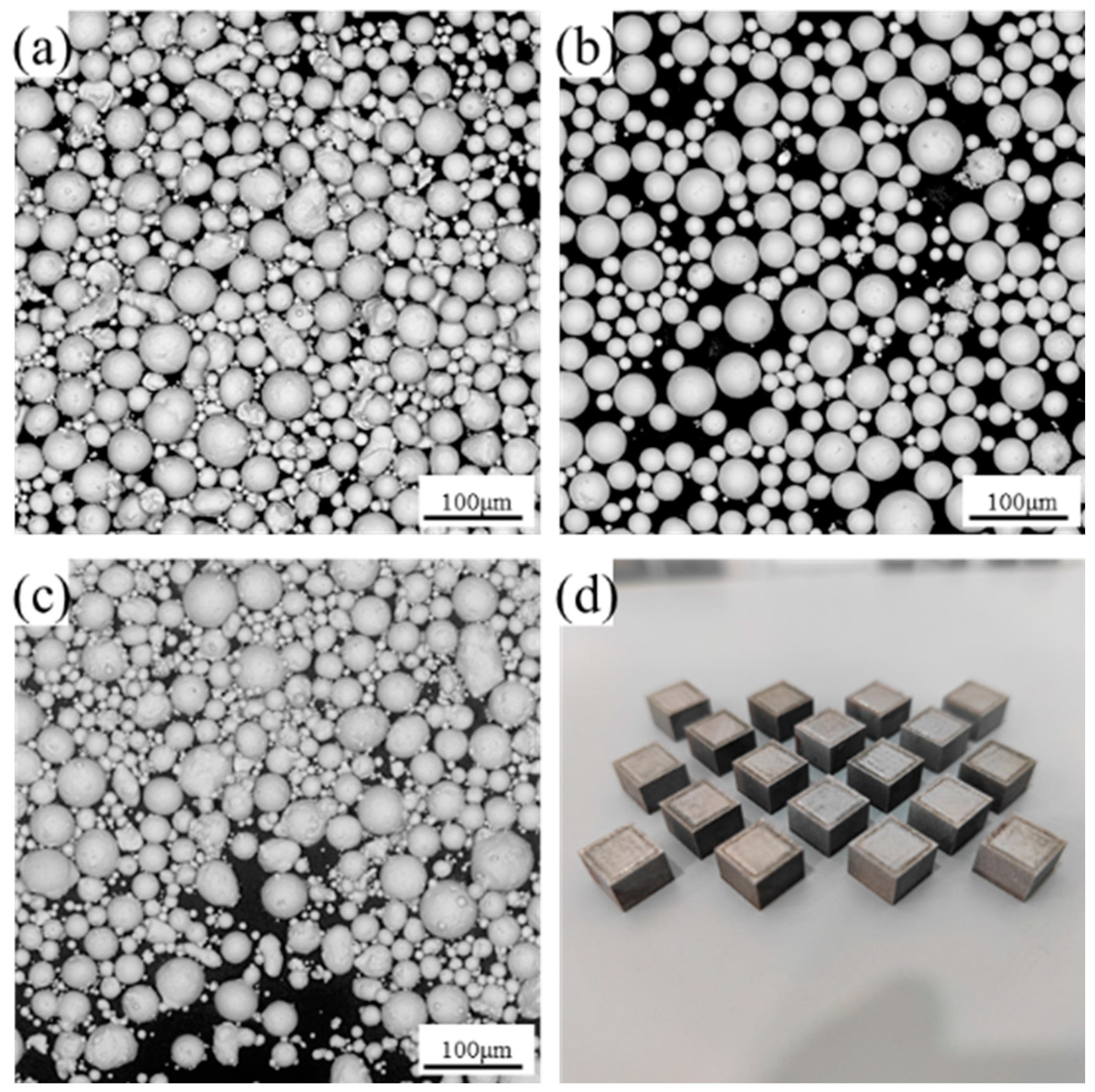
2.1. Specimen Preparation

The commercial powders of Fe, Cr and Co were mixed with a weight ratio of 60:25:15 to obtain the Fe-25Cr-15Co permanent magnets. Figure 1 shows the SEM images of the Fe, Cr and Co elemental powder and the optical photograph of as-built samples. The powder particles are spherical with a particle size of 15-53 μm and have good fluidity, and are very suitable for the SLM process [23]. For specimen preparation, a commercial DLM-120HT machine from China Iron and Steel Research Institute Group Co., Ltd. (Beijing, China) was used, which is equipped with a 500 W single-mode fiber laser (wavelength 1064 nm). The size of the printed specimen was 10 mm × 10 mm × 8 mm. SLM AM was performed under an argon atmosphere with an oxygen content below 0.02% to prevent oxidation. The layer thickness, laser spot size and hatch space were set as 25 μm, 60 μm and 100 μm, respectively. Two combinations of laser power and scanning speed were used in this study, 200 W, 900 mm/s and 250 W, 700 mm/s, respectively. The laser process melted each layer twice at 200 W–900 mm/s, marked as P1. P2 was a laser process that melted each layer twice at 200 W–900 mm/s and once at 250 W–700 mm/s. A laser process in which each layer was melted twice at 200 W–900 mm/s and twice at 250 W–700 mm/s was denoted as the P3 process.
The Fe-25Cr-15Co permanent magnets in an isotropic state were obtained after a series of HT procedures. The solid solution HT process was set at 1300 °C for 1 h, 1300 °C for 3 h and 1300 °C for 5 h in the vacuum environment, followed by quenching using a water bath. The annealing HT was performed at 620–670 °C for 50 min. All samples went through an additional multi-stepped aging process. The multi-stepped aging process was at 620 °C for 1 h, 600°C for 2 h, 580 °C for 3 h, 560 °C for 4 h, 540 °C for 5 h and 520 °C for 5 h. HT processes with or without solution treatment, including annealing and multi-stepped aging, were referred to as the ‘SAA’ process and ‘AA’ process, respectively.

2.2. Characterizations

The density of as-built blocks was determined by the Archimedes method. The macrostructure was examined using an Olympus X53 optical microscope (Olympus China Co., Ltd., Shanghai, China). The microstructures were investigated with a scanning electron microscope (SEM) of Phenom ProX-SE desktop (Phenom-world, Eindhoven, the Netherlands) equipped with an X-ray energy dispersive spectrometer (EDS) detector. X-ray diffraction (XRD) was taken with a Bruker D8 Advance X-ray diffractometer (Bruker Corporation, Billerica, MA, USA) equipped with Cu Kα radiation. The operating voltage and current were 40 kV and 40 mA, respectively. XRD patterns were recorded in the angle range from 35° to 120° with a step of 0.9 °/min. Magnetic properties were measured under an applied field of 1.5 T by vibrating sample magnetometry (VSM) in a physical property measurement system (PPMS, Quantum Design Co., Ltd., San Diego, CA, USA). The 3 mm tall by 3 mm diameter cylinders were machined for magnetic property measurements. Transmission electron microscopy (TEM) was performed by an FEI Tecnai G2 F20 transmission electron microscope (FEI Technologies Inc., Hillsboro, OR, USA) running at 200 kV. The thin foil used for TEM was ground to 50 μm using SiC sandpaper and punched into 3 mm circular plates. The TEM foils were electropolished in a perchloric acid/ethanol solution (the proportion was 1/9) at −20 °C, and the working current was 60 mA. Vickers hardness tests were measured using an MH-500 tester (Everyone Instrument Co., Ltd., Shanghai, China) with a diamond indenter under a load of 500 g for a holding time of 15 s. Compression tests were carried out on a universal mechanical testing machine (MTS880-25T, MTS, Eden Prairie, MN, USA) at room temperature using cylindrical specimens of 10 mm in diameter and 20 mm in height. The loading rate was 0.005 mm/min during compression tests.

3. Results and Discussion

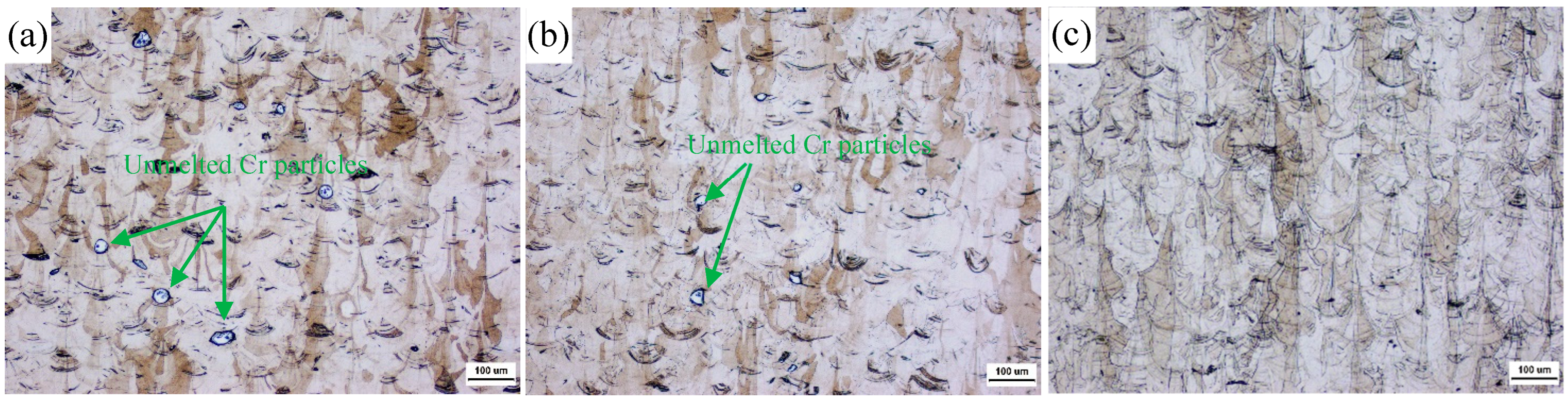
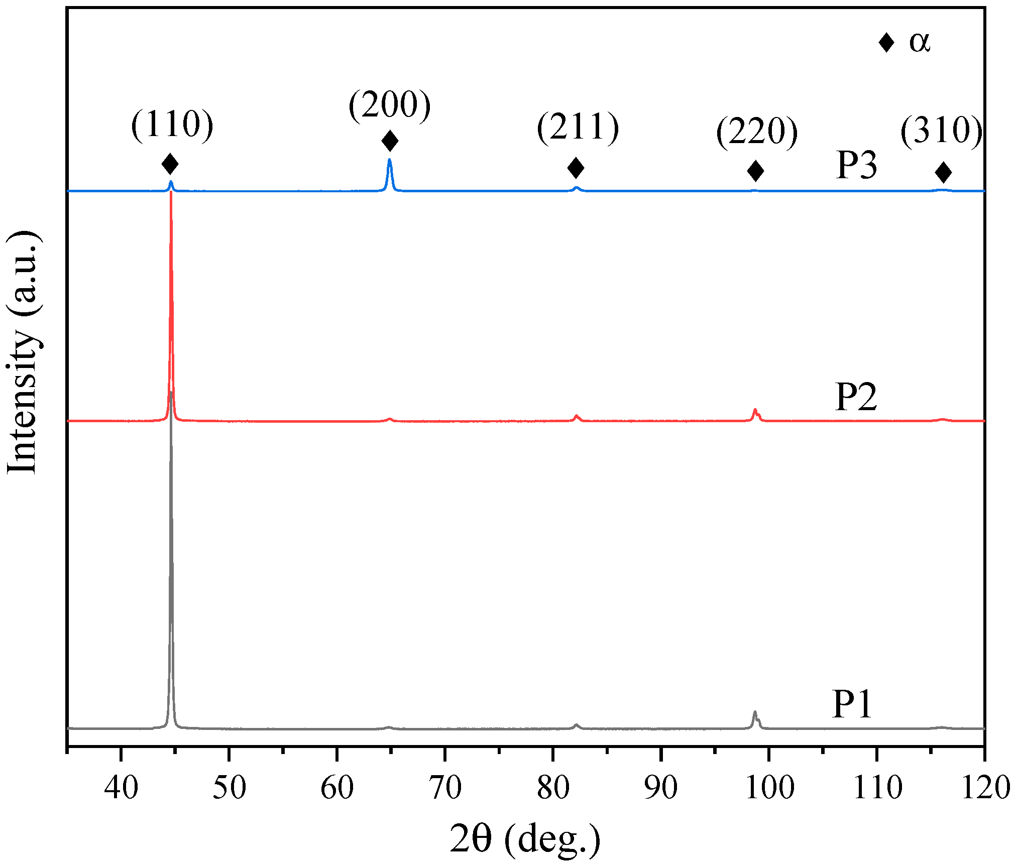
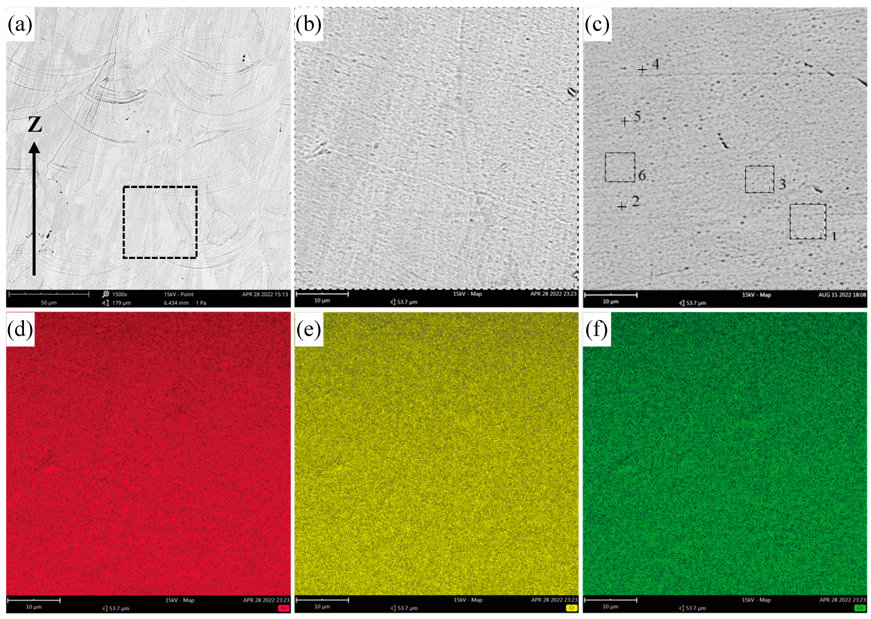
3.1. Forming Behavior

After some exploratory experiments, the remelting process was used to prepare Fe-25Cr-15Co permanent magnets. The as-built Fe-25Cr-15Co samples have superb formability and no cracks or delamination on their surfaces, (Figure 1d). The densities of samples under the P1, P2 and P3 processes were 7.7054 g/cm3, 7.7013 g/cm3 and 7.7052 g/cm3, respectively. The theoretical density of Fe-25Cr-15Co (wt.%) alloy is 7.7580 g/cm3, calculated by Thermo-Calc software. The as-built sample under the P3 process has a relative density (ρrel) of about 99.32%, which is higher than the magnet prepared by conventional powder metallurgy. For example, for Fe-30Cr-16Co alloy prepared by sintering process: ρrel = 93–98% [7]; Fe-24Cr-15Co-3Mo-1.5Ti alloy prepared by sintering process: ρrel = 98% [8]; Fe-26Cr-16Co-2Mo-2W prepared by sintering and hot rolling process: ρrel = 97–98% [9].
The metallographic graphs of the XZ plane (parallel to the building direction) of the as-built samples under the P1, P2 and P3 processes are shown in Figure 2. It can be seen that there are many un-melted Cr particles under the P1 process, (Figure 2a). Due to the high melting point of the Cr element and the high content of Cr in Fe-25Cr-15Co composition, greater laser energy is needed. With the increase in laser remelting times, the lack of fusion of Cr particles decreases, (Figure 2b). In addition, under P1 and P2 processes, obvious grain morphology cannot be seen in the sample with uneven composition except for the presence of un-melted regions, (Figure 2a,b). However, under the P3 process, no un-melted Cr particles were observed and the sample exhibited typical 3D printing grain morphology, (Figure 2c). In situ alloying of Fe, Cr and Co elemental powders was completed by the P3 laser multiple remelting processes. Multiple remelting processes increase the laser energy inside the molten pool, expand the size of it, and push internal liquid flows. In the meantime, the previously solidified parts were remelted to the liquid pool which can promote the composition homogenization and in situ alloy.
The XRD patterns of Fe-25Cr-15Co as-built samples under different processes are illustrated in Figure 3. Only the body-centered-cubic (bcc) α phase was detected, and there was no unwanted paramagnetic σ or γ phase [24,25], mainly due to the fact that the cooling rate during the SLM process is about 105–106 K/s [26,27], which can be very effective to bypass their formation. However, the diffraction peaks of P1 and P2 processes have extremely high intensity at 2θ of 44.37° compared with the P3 process, which is likely to be caused by un-melted Cr particles. According to a previous study [28], Cr has a bcc α phase structure and an identical diffraction peak at 2θ of 44.37° (PDF, No: 89-4055). Therefore, Cr particles with a large volume fraction under P1 and P2 processes result in high diffraction intensity, which is confirmed by the result of microstructure analysis in the previous section. The structure of the sample under the P3 process is consistent with that of the sample prepared by the traditional method, which indicates that complete in situ alloying between Fe, Cr and Co is achieved after multiple remelting which involves melting of Fe, Cr and Co powder particles, alloying in the liquid and solidification of the liquid.
SEM and EDS mapping observations parallel to the building direction (Z direction) of the sample under the P3 process were performed. As shown in Figure 4d–f, the elements of Fe, Cr and Co are seen to be evenly distributed in the as-built sample, without any element segregation. Components of several microregions randomly selected on the XZ plane (marked in Figure 4c) were detected. The results are shown in Table 1. The average composition of the printed sample deviates slightly from the preset powder composition. We attribute this to the burning loss and vaporization of elements during the process of laser melting, which has been reported in other works of literature [29,30,31]. Compared with the average composition value, the Cr element in the microregions has the largest component deviation, and the deviation value is only 2.84%. We believe that the Fe-25Cr-15Co alloy obtained exceptional forming quality under the P3 process. In the following studies, samples for magnetic property analysis and mechanical property analysis were obtained under this process.

3.2. Magnetic Behavior

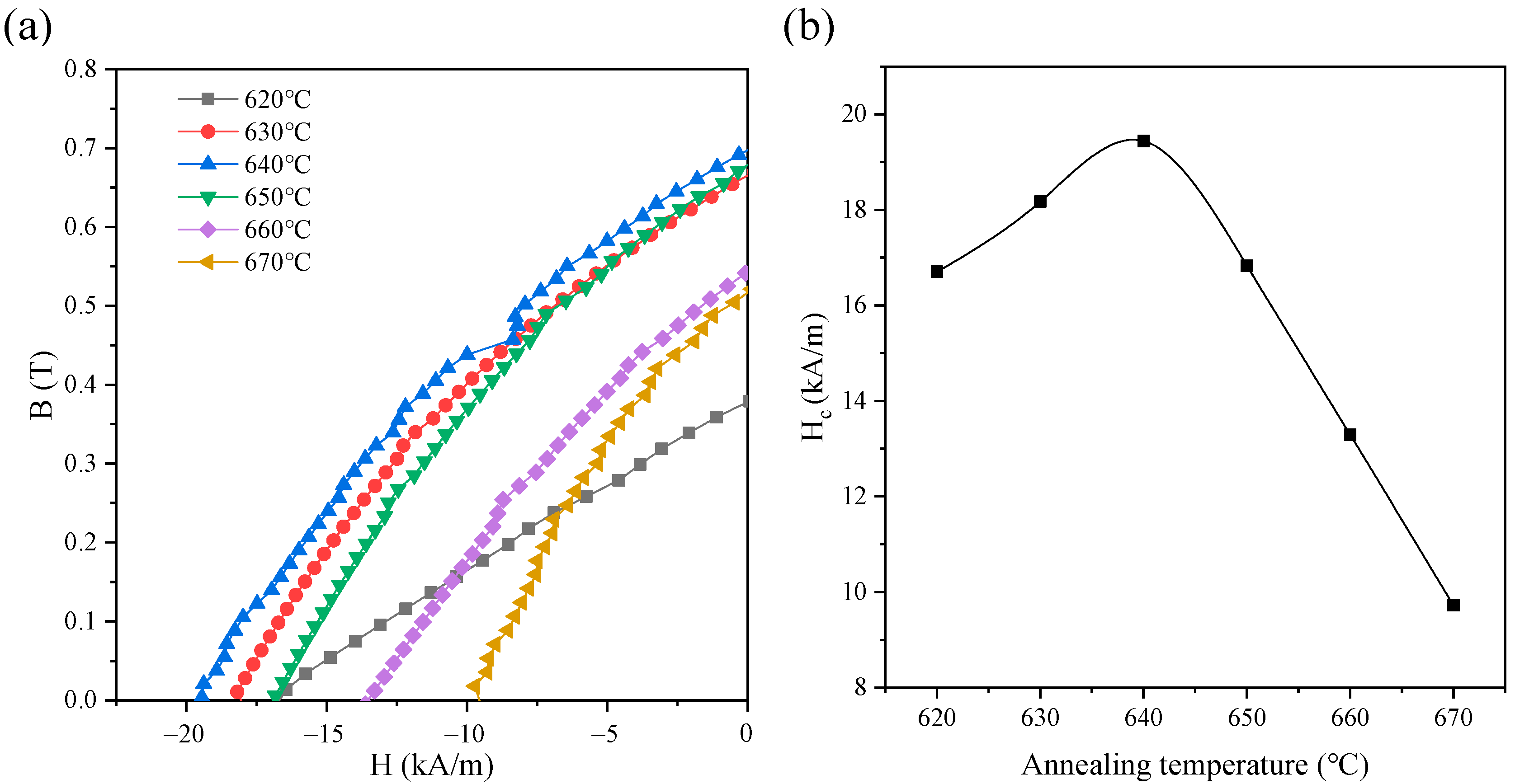
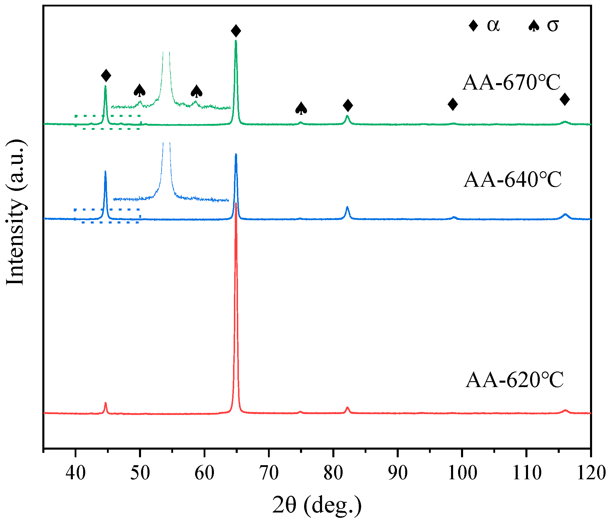
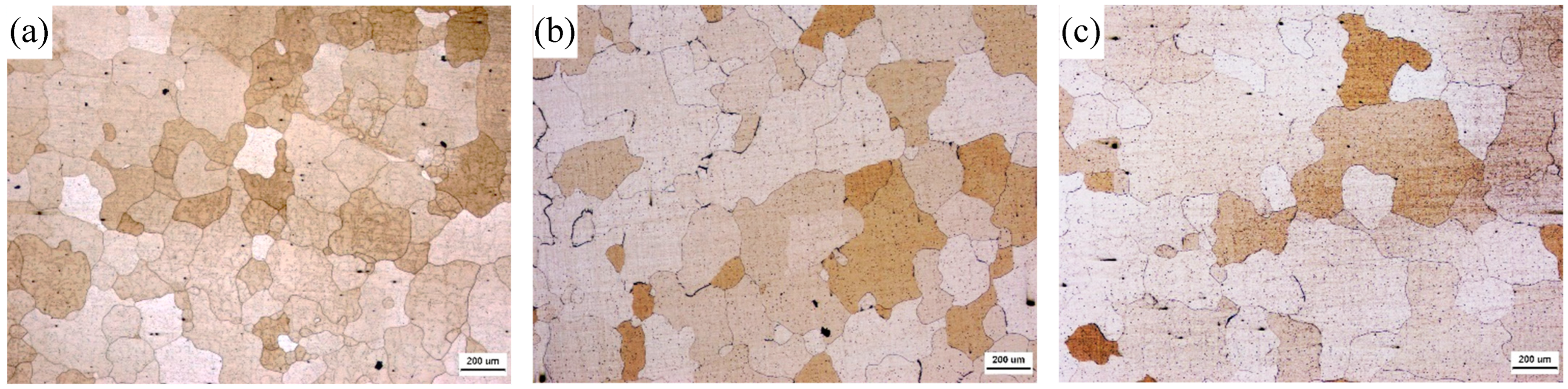
3.2.1. Effect of Annealing Treatment

The Fe-Cr-Co base permanent magnets undergo spinodal decomposition under appropriate conditions into Fe-rich α1 ferromagnetic phase and the Cr-rich α2 paramagnetic phase to create desirable magnetic properties. The spinodal decomposition is very sensitive to the decomposition temperature [32]. For this reason, the effect of annealing temperature on the magnetic properties of as-printed magnets is discussed. Figure 5a presents the demagnetization curves of Fe-25Cr-15Co samples after the AA process. The annealing was performed at 620–670 °C for 50 min. The corresponding coercive force (Hc) is shown in Figure 5b.
As shown in Figure 5b, the optimal coercivity was obtained when the annealing temperature was 640 °C. With the increase in annealing temperature, the coercivity of the magnet decreases sharply, which may be due to the formation of a paramagnetic phase in the magnet. Therefore, the XRD patterns of the magnets treated in the AA process are shown in Figure 6. The XRD pattern showed that the single-phase structure of the bcc α phase was still maintained in the sample treated in the AA process with lower annealing temperature. However, after the AA process with an annealing temperature of 670 °C, the two-phase structures of the α phase and a small amount of unwanted σ phase have been detected. σ phase is paramagnetic, which seriously deteriorates the magnetic properties of magnets [25]. This explains the reason for the serious decline in magnet performance. Therefore, the best annealing temperature of 640 °C was used in the following research.

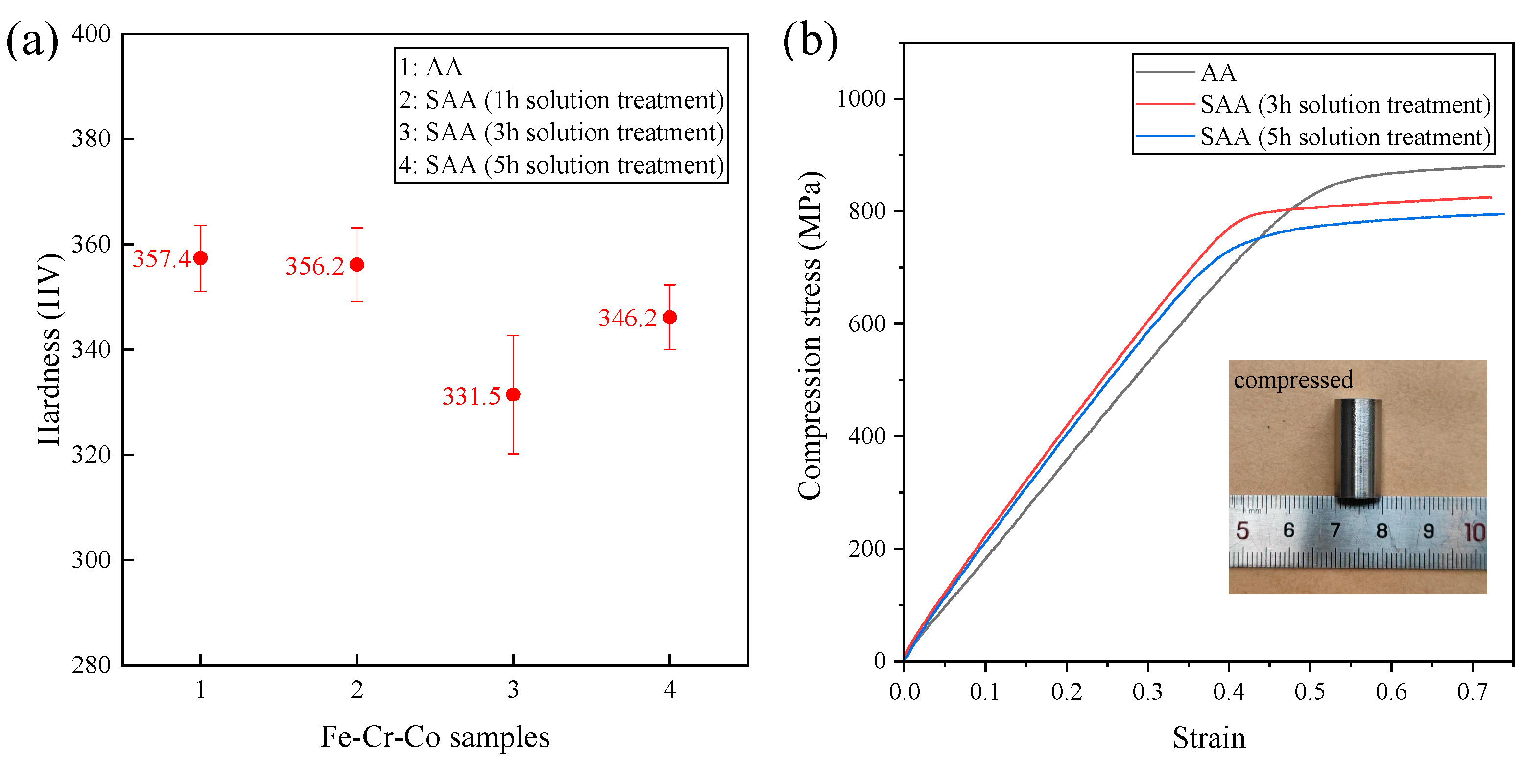
3.2.2. Effect of Solid Solution Treatment

In traditional casting and powder metallurgy processes, supersaturated solid solution α phase is usually obtained by a high-temperature solid solution and quenching process [33,34]. In this article, the influence of the solid solution process on magnetic properties was also evaluated. After solution treatment, the sample was annealed at 640 °C for 50 min and then subjected to multi-stage aging. In Figure 7, the optical images of the samples after solid solution treatment are shown. The investigation of these microstructures showed that the typical 3D printing grain morphology observed in the microstructure of the as-built block (Figure 2c) disappeared. Another point that can be seen from the microstructure of the samples is that with the increase in holding time of the solid solution process, the α phase grain size of the solid solution-treated samples is enhanced.
The magnetic hysteresis loops of the samples after SAA treatment measured by VSM are represented in Figure 8. The vertical and horizontal coordinates represent the saturation magnetization (Ms) and Hc from the VSM test, respectively. It can be found that when the applied magnetic field is greater than 1000 kA/m, the samples reach magnetic saturation. The Ms of several types of samples has little difference, and it is around 1250 kA/m (Figure 8a). The obtained magnetic properties of Fe-25Cr-15Co alloys based on the demagnetization curves (B-H) are listed in Table 2.
The magnetic properties of the as-built sample with AA treatment were obtained as Hc = 19.44 kA/m, Br = 0.69 T and (BH)max = 4.54 kJ/m3. Solid solution treatment improves the magnetic properties of the as-built magnets, which can be attributed to the further homogenization of microregion components. The magnetic properties of the sample with SAA (3 h solution treatment) are Hc = 22.84 kA/m, Br = 0.86 T and (BH)max = 7.98 kJ/m3. However, with the further increase in solution treatment time, the magnetic properties of magnets decrease, which may be related to the coarse grain size of the α phase. Grain boundary hinders the irreversible motion of domain walls. The augmentation of grain size decreases the coercivity of the magnetic materials. The magnetic properties obtained in this work are better than the properties prepared by the methods of powder metallurgy reported in further literature. The magnetic properties of the hard magnetic alloy Fe-24Cr-15Co-3Mo-1.5 Ti (wt.%) in an isotropic state are Hc = 22.2 kA/m, Br = 0.56 T and (BH)max = 3.5 kJ/m3 [8]. It should be noted that the addition of Mo, Ti, Nb and V in Fe-Cr-Co alloy improves the stability and hysteresis properties of the ferromagnetic phase and promotes the magnetic properties [3,35,36]. However, the magnetic properties obtained in this study fall below the values reported for Fe-Cr-Co alloys annealed under an external magnetic field [8,37]. TEM analysis shows the morphology of the spinodal decomposition phases in the Fe-25Cr-15Co sample, as shown in Figure 9. Since the atomic number of Fe and Co is higher than that of Cr, we deduced that the α1 phase (bright patch) was rich in Fe and Co, while the α2 matrix phase (dark network) was rich in Cr. The morphology showed that the distribution of the α1 phase on the α2 matrix was isotropic, which was consistent with the expectation that there is no orientation effect of an external magnetic field.

3.3. Mechanical Behavior

The mechanical properties of Fe-25Cr-15Co samples were also investigated. When the spinodal decomposition of Fe-25Cr-15Co occurs, component fluctuations produce two solid solutions, causing lattice mismatch that brings about coherent internal stress, enhancing the hardness [14,38]. Figure 10a displays the Vickers hardness for Fe-25Cr-15Co samples. The average microhardness of the as-built sample after AA treatment is about 357.4 HV, which is equivalent to that of the sample with SAA (1 h solution treatment). With the further increase in solution time, the hardness of the sample with SAA (3 h solution treatment) decreased to 331.5 HV. This behavior is attributed to the coarse grain developed during the solid solution treatment process. Fe-Cr-Co permanent magnet materials have lower hardness, which means they have better plasticity and toughness, which is better for permanent magnet materials. Figure 10b shows the compressive stress–strain curves of Fe-25Cr-15Co samples. The yield strength of the sample with SAA (3 h solution treatment) is 801 MPa and specimens did not break during compressive testing, indicating that the SLM Fe-25Cr-15Co alloy is highly ductile.

4. Conclusions

In this paper, Fe-25Cr-15Co permanent magnets have been fabricated via selective laser melting and in situ alloying from a blend of Fe, Cr and Co elemental powders for the first time. The conclusions are as follows:
1. The preparation process of Fe-Cr-Co magnetic material was optimized. The optimal laser process is laser scanning twice with a power of 200 W and speed of 900 mm/s and laser scanning twice with a power of 250 W and speed of 700 mm/s. The as-built samples with uniform composition and high density without defects such as holes and unmelted particles were prepared under the optimal laser process, and the as-built samples have a relative density of about 99.32% (7.705 g/cm3), which is higher than the magnet prepared by the conventional method.
2. The as-built samples possess a single-phase structure of α phase. The hard magnetic alloy Fe-25Cr-15Co in an isotropic state was obtained by thermal treatment without an external magnetic field. Magnetic properties of as-built samples treated at an annealing temperature range of 620–670 °C and with multi-stepped aging were investigated. The optimal coercivity is obtained when the annealing temperature is 640 °C. A remarkable decrease in coercivity is observed when the annealing temperature is 670 °C. The σ phase has been detected, which can explain the decrease in magnetic properties of magnets. The magnetic properties of the as-built sample were obtained after solid solution treatment, annealing and multi-stepped aging as Hc = 22.84 kA/m, Br = 0.86 T and (BH)max = 7.98 kJ/m3, which is better than the values reported for Fe-Cr-Co alloys in an isotropic state fabricated by the conventional method.
3. The hardness of Fe-25Cr-15Co permanent magnets obtained in this study is above 331.5 HV; the yield strength is more than 800 MPa, indicating they have excellent mechanical properties.
The findings of this study proved the feasibility of combining the Fe-Cr-Co permanent magnet materials and SLM in situ alloying technology in fabricating gradient structures or complex shape applications where variable magnetic circuit characteristics are needed.

Author Contributions

Data curation, Y.H. (Yazhou He) and H.Z.; formal analysis, Y.H. (Yazhou He) and P.S.; investigation, Y.H. (Yazhou He), H.Z., P.S. and Y.H. (Yaqing Hou); Conceptualization, H.S.; methodology, H.S. and D.Z.; software, H.S.; validation, H.Z. and P.S.; funding acquisition, H.S. and Y.H. (Yaqing Hou); supervision, H.S.; writing—original draft preparation, Y.H. (Yazhou He); writing—review and editing, H.S. All authors have read and agreed to the published version of the manuscript.

Funding

This research was funded by the National Key Research and Development Program of China (Grant No. 2021YFB3702500).

Institutional Review Board Statement

Not applicable.

Informed Consent Statement

Not applicable.

Data Availability Statement

The data presented in this study are available upon request from the corresponding author.

Acknowledgments

This work is supported by grants from the National Key Research and Development Program of China (Grant No. 2021YFB3702500). The authors are very grateful to the reviewers and editors for their valuable suggestions, which have helped improve the paper substantially.

Conflicts of Interest

The authors declare no conflict of interest.

References

  1. Kaneko, H.; Homma, M.; Nakamura, K. New Ductile Permanent Magnet of Fe-Cr-Co System. AIP Conf. Proc 1972, 5, 1088–1092. [Google Scholar] [CrossRef]
  2. Sugimoto, S.; Okada, M.; Homma, M. The enhancement of the magnetic properties of Fe-Cr-Co-Mo polycrystalline permanent magnet alloys by cold rolling and annealing. J. Appl. Phys. 1988, 63, 3707–3709. [Google Scholar] [CrossRef]
  3. Mohseni Zonoozi, E.; Kianvash, A. Microstructure, magnetic and mechanical properties of Fe–28Cr–15Co–1Si cast magnets containing Mo and Ti additives. Appl. Phys. A 2020, 126, 720. [Google Scholar] [CrossRef]
  4. Belozerov, E.V.; Mushnikov, N.V.; Ivanova, G.V.; Shchegoleva, N.N.; Serikov, V.V.; Kleinerman, N.M.; Vershinin, A.V.; Uimin, M.A. High-strength magnetically hard Fe-Cr-Co-based alloys with reduced content of chromium and cobalt. Phys. Met. Met. 2012, 113, 319–325. [Google Scholar] [CrossRef]
  5. Han, X.-h.; Li, Y.; Zhao, Y.; Chi, X.; Zhang, C.; Bian, L.; Sun, J.-b.; Zhang, Y. Microstructure and phase transition of Fe-24Cr-12Co-1.5Si ribbons. J. Alloys Compd. 2018, 731, 10–17. [Google Scholar] [CrossRef]
  6. Jin, S.; Chin, G. Fe-Cr-Co magnets. IEEE Trans. Magn. 1987, 23, 3187–3192. [Google Scholar] [CrossRef]
  7. Ustyukhin, A.S.; Ankudinov, A.B.; Zelensky, V.A.; Alymov, M.I.; Milyaev, I.M.; Vompe, T.A. Synthesis, thermal treatment, and characterization of sintered hard magnetic Fe–30Cr–16Co alloy. J. Alloys Compd. 2022, 902, 163754. [Google Scholar] [CrossRef]
  8. Vompe, T.A.; Milyaev, I.M. Magnetic properties of the Fe-24%Cr-15%Co-3%Mo-1.5%Ti hard magnetic alloy in anisotropic and isotropic states. IOP Conf. Ser. Mater. Sci. Eng. 2020, 848, 012096. [Google Scholar] [CrossRef]
  9. Ustyukhin, A.S.; Ankudinov, A.B.; Zelenskii, V.A.; Milyaev, I.M.; Alymov, M.I. Improvement of magnetic properties by hot rolling of sintered powder alloy in the Fe–Cr–Co system. Dokl. Phys. Chem. 2017, 476, 193–196. [Google Scholar] [CrossRef]
  10. Reza Amini, R.; Ali, G.; Majid, T.; Mazaher, R. Magnetic features of Fe-Cr-Co alloys with tailoring chromium content fabricated by spark plasma sintering. J. Magn. Magn. Mater. 2017, 426, 744–752. [Google Scholar] [CrossRef]
  11. Lin, Z.; Zhaolong, X.; Xiaodi, L.; Engang, W. Spinodal Decomposition in Fe-25Cr-12Co Alloys under the Influence of High Magnetic Field and the Effect of Grain Boundary. Nanomaterials 2018, 8, 578. [Google Scholar] [CrossRef]
  12. Altafi, M.; Ghasemi, A.; Sharifi, E.M. The influence of cold rolling and thermomagnetic treatment on the magnetic and mechanical properties of Fe-23Cr-9Co alloy. J. Magn. Magn. Mater. 2019, 491, 165537. [Google Scholar] [CrossRef]
  13. Masoud, A.; Ehsan Mohammad, S.; Ali, G. The effect of various heat treatments on the magnetic behavior of the Fe-Cr-Co magnetically hard alloy. J. Magn. Magn. Mater. 2020, 507, 166837. [Google Scholar] [CrossRef]
  14. Zhaolong, X.; Lin, Z.; Yan, X.; Bailing, A.; Rongmei, N.; Masoud, M.; Theo, S.; Jun, L.; Robert, E.G.; Tiannan, M.; et al. Ultrafine microstructure and hardness in Fe-Cr-Co alloy induced by spinodal decomposition under magnetic field. Mater. Des. 2021, 199, 109383. [Google Scholar] [CrossRef]
  15. Popovich, A.A. Additive Technologies as Breakthrough Solutions for Creating Advanced Functional Materials. Met. Sci. Heat Treat. 2020, 62, 18–24. [Google Scholar] [CrossRef]
  16. Reichardt, A.; Shapiro, A.A.; Otis, R.; Dillon, R.P.; Borgonia, J.P.; McEnerney, B.W.; Hosemann, P.; Beese, A.M. Advances in additive manufacturing of metal-based functionally graded materials. Int. Mater. Rev. 2021, 66, 1–29. [Google Scholar] [CrossRef]
  17. Hou, Y.; Su, H.; Zhang, H.; Wang, X.; Wang, C. Fabricating Homogeneous FeCoCrNi High-Entropy Alloys via SLM In Situ Alloying. Metals 2021, 11, 942. [Google Scholar] [CrossRef]
  18. Fischer, M.; Joguet, D.; Robin, G.; Peltier, L.; Laheurte, P. In situ elaboration of a binary Ti–26Nb alloy by selective laser melting of elemental titanium and niobium mixed powders. Mater. Sci. Eng. C 2016, 62, 852–859. [Google Scholar] [CrossRef]
  19. Surmeneva, M.A.; Koptyug, A.; Khrapov, D.; Ivanov, Y.F.; Mishurova, T.; Evsevleev, S.; Prymak, O.; Loza, K.; Epple, M.; Bruno, G.; et al. In situ synthesis of a binary Ti–10at% Nb alloy by electron beam melting using a mixture of elemental niobium and titanium powders. J. Mater. Processing Technol. 2020, 282, 116646. [Google Scholar] [CrossRef]
  20. Martinez, R.; Todd, I.; Mumtaz, K. In situ alloying of elemental Al-Cu12 feedstock using selective laser melting. Virtual Phys. Prototyp. 2019, 14, 242–252. [Google Scholar] [CrossRef]
  21. Zhang, B.; Chen, J.; Coddet, C. Microstructure and Transformation Behavior of in-situ Shape Memory Alloys by Selective Laser Melting Ti–Ni Mixed Powder. J. Mater. Sci. Technol. 2013, 29, 863–867. [Google Scholar] [CrossRef]
  22. Wang, C.; Tan, X.P.; Du, Z.; Chandra, S.; Sun, Z.; Lim, C.W.J.; Tor, S.B.; Lim, C.S.; Wong, C.H. Additive manufacturing of NiTi shape memory alloys using pre-mixed powders. J. Mater. Process. Technol. 2019, 271, 152–161. [Google Scholar] [CrossRef]
  23. Borgman, J.M.; Conway, P.P.; Torres-Sanchez, C. The use of inorganic process control agents to mill titanium-niobium powders suitable for the selective laser melting process. Powder Technol. 2022, 407, 117546. [Google Scholar] [CrossRef]
  24. Szymura, S.; Sojka, L. Structure and Magnetic Properties of Fe-Cr-Co-Mo Alloy Melted in Open Induction Furnance. Met Sci 1979, 13, 320–321. [Google Scholar]
  25. Mukhamedov, B.O.; Ponomareva, A.V.; Abrikosov, I.A. Spinodal decomposition in ternary Fe-Cr-Co system. J. Alloys Compd. 2017, 695, 250–256. [Google Scholar] [CrossRef]
  26. Wang, X.; Carter, L.N.; Pang, B.; Attallah, M.M.; Loretto, M.H. Microstructure and yield strength of SLM-fabricated CM247LC Ni-Superalloy. Acta Mater. 2017, 128, 87–95. [Google Scholar] [CrossRef]
  27. Ma, M.; Wang, Z.; Zeng, X. A comparison on metallurgical behaviors of 316L stainless steel by selective laser melting and laser cladding deposition. Mater. Sci. Eng. A 2017, 685, 265–273. [Google Scholar] [CrossRef]
  28. Straumanis, M.E.; Weng, C.C. The Absorption and Refraction Corrections and the Lattice Constant of Chromium. Am. Mineral. 1956, 41, 437–448. [Google Scholar]
  29. Yin, J.; Zhang, W.; Ke, L.; Wei, H.; Wang, D.; Yang, L.; Zhu, H.; Dong, P.; Wang, G.; Zeng, X. Vaporization of alloying elements and explosion behavior during laser powder bed fusion of Cu–10Zn alloy. Int. J. Mach. Tools Manuf. 2021, 161, 103686. [Google Scholar] [CrossRef]
  30. Beiranvand, Z.M.; Ghaini, F.M.; Naffakh-moosavy, H.; Sheikhi, M.; Torkamany, M.J. Magnesium Loss in Nd:YAG Pulsed Laser Welding of Aluminum Alloys. Metall. Mater. Trans. B 2018, 49, 2896–2905. [Google Scholar] [CrossRef]
  31. Zhuo, L.; Song, B.; Li, R.; Wei, Q.; Yan, C.; Shi, Y. Effect of element evaporation on the microstructure and properties of CuZnAl shape memory alloys prepared by selective laser melting. Opt. Laser Technol. 2020, 127, 106164. [Google Scholar] [CrossRef]
  32. Jin, S.; Chin, G.; Wonsiewicz, B. A low cobalt ternary Cr-Co-Fe alloy for telephone receiver magnet use. IEEE Trans. Magn. 1980, 16, 139–146. [Google Scholar] [CrossRef]
  33. Milyaev, I.M.; Milyaev, A.I.; Yusupov, V.S.; Laisheva, N.V.; Lazorenko, G.Y. Effect of Heat Treatment on the Magnetic Hysteretic Properties of an Isotropic Hard Magnetic Fe–30Cr–14Co Alloy. Russ. Metall. (Met.) 2022, 2022, 245–249. [Google Scholar] [CrossRef]
  34. Xu, X.; Westraadt, J.E.; Odqvist, J.; Youngs, T.G.A.; King, S.M.; Hedström, P. Effect of heat treatment above the miscibility gap on nanostructure formation due to spinodal decomposition in Fe-52.85 at.%Cr. Acta Mater. 2018, 145, 347–358. [Google Scholar] [CrossRef]
  35. Kaneko, H.; Homma, M.; Minowa, T. Effect of V and V + Ti additions on the structure and properties of Fe-Cr-Co ductile magnet alloys. IEEE Trans. Magn. 1976, 12, 977–979. [Google Scholar] [CrossRef]
  36. Wu, X.; Bu, S.; Han, X.; Zhang, C.; Sun, J.; Zhang, Y.; Pan, Y. Effects of Si and/or Ti Addition on the Microstructure and Magnetic Properties of Fe–Cr–Co Ribbons. IEEE Trans. Magn. 2017, 53, 2100208. [Google Scholar] [CrossRef]
  37. Sun, X.Y.; Xu, C.Y.; Zhen, L.; Lu, L.X.; Qin, L.C. Spinodal decomposition in Fe–25Cr–12Co–1Si alloy under a 100kOe magnetic field. J. Magn. Magn. Materials. 2006, 306, 69–72. [Google Scholar] [CrossRef]
  38. Suzudo, T.; Takamizawa, H.; Nishiyama, Y.; Caro, A.; Toyama, T.; Nagai, Y. Atomistic modeling of hardening in spinodally-decomposed Fe–Cr binary alloys. J. Nucl. Mater. 2020, 540, 152306. [Google Scholar] [CrossRef]
Figure 1. SEM images of (a) Fe elemental powder, (b) Cr elemental powder, (c) Co elemental powder and (d) as-built Fe-25Cr-15Co blocks.
Metals 12 01634 g001
Figure 2. Optical micrographs of the XZ plane (parallel to the building direction) of as-built samples; (a) the sample under the P1 process, (b) the sample under the P2 process, (c) the sample under the P3 process.
Metals 12 01634 g002
Figure 3. Diffraction patterns of as-built samples under different processes.
Metals 12 01634 g003
Figure 4. (a) SEM image of the as-built sample under the P3 process (Z direction). (b) Amplified SEM photographs in the virtual frame of (a). (c) Microregional component analysis. (df) EDS elemental mapping corresponding to (b), d: Fe, e: Cr, f: Co.
Metals 12 01634 g004
Figure 5. (a) Demagnetization curves of Fe-25Cr-15Co samples treated at different annealing temperatures and (b) the corresponding Hc.
Metals 12 01634 g005
Figure 6. Diffraction patterns for in situ Fe-25Cr-15Co as-built samples treated in AA process.
Metals 12 01634 g006
Figure 7. Optical images of the samples after solid solution treatment; (a) 1300 °C for 1 h, (b) 1300 °C for 3 h, (c) 1300 °C for 5 h.
Metals 12 01634 g007
Figure 8. (a) Magnetic hysteresis loops (M-H) and (b) demagnetization curves (B-H) of Fe-25Cr-15Co alloys under different thermal treatments.
Metals 12 01634 g008
Figure 9. Bright-field image of the Fe-25Cr-15Co alloy with SAA (1 h solution treatment); (a) at lower magnification and (b) at higher magnification.
Metals 12 01634 g009
Figure 10. (a) Average microhardness in hardness tests and (b) deformation curves in compression tests of Fe-25Cr-15Co samples.
Metals 12 01634 g010
Table 1. Chemical composition of microregions marked in Figure 4c.
Element Composition (wt.%)FeCrCo
EDSRegion 161.8821.6816.44
Point 261.9921.8516.16
Region 361.9721.7216.31
Point 462.0921.4516.46
Point 561.7922.4215.79
Region 662.2221.6616.12
Average value61.9921.8016.21
Composition deviation0.37%2.84%2.59%
Note: Deviation = max E D S   c o m p o s i t i o n A v e r a g e   v a l u e A v e r a g e   v a l u e × 100%.
Table 2. The magnetic properties of Fe-25Cr-15Co alloys under different thermal treatments.
SamplesHc (kA/m)Br (T)(BH)max (kJ/m3)
AA 19.440.694.54
SAA (1 h solution treatment)22.350.847.24
SAA (3 h solution treatment)22.840.867.98
SAA (5 h solution treatment)18.770.704.41
Publisher’s Note: MDPI stays neutral with regard to jurisdictional claims in published maps and institutional affiliations.

