Article

Effects of Laser-Deposited Maraging Steel on L-PBF 316L Component

Department of Mechanics, Mathematics and Management, Polytechnic University of Bari, Via Orabona 4, 70125 Bari, Italy
*
Author to whom correspondence should be addressed.
Metals 2022, 12(10), 1669; https://doi.org/10.3390/met12101669
Submission received: 31 August 2022 / Revised: 27 September 2022 / Accepted: 4 October 2022 / Published: 5 October 2022
(This article belongs to the Section Additive Manufacturing)

Abstract

:
The capabilities of additive manufacturing (AM) techniques have been extensively examined in the literature. However, scientific gaps persist on the feasibility of realizing a coated component manufactured by using various materials processed by combining different AM processes. From this perspective, this study focuses on the manufacturing of a directed energy deposition (DED) coating by using 18Ni (300) maraging steel powder on AISI 316L components realized by laser-powder bed fusion (L-PBF), in order to assess the production of components with high geometrical complexity combined with high mechanical surface properties in selected areas. The quality of the manufactured coatings was assessed in-process through the implementation of an optical monitoring system and real-time image processing. In addition, an in-depth metallurgical analysis (microstructural and chemical) of the interface between the DED coating and the L-PBF component was carried out. Finally, hardness tests were performed on both the as-deposited and heat-treated coatings to confirm the high mechanical performance of the final component surface. The results revealed the potential of producing cost-effective and geometrically complex parts, such as molds or tools with internal cooling channels, that implement mechanically high-performance surfaces.

1. Introduction

In 2020, the additive manufacturing (AM) sector produced more than $11 billion worth of products. The development of metal additive manufacturing (MAM) technologies, such as laser-powder bed fusion (L-PBF) and directed energy deposition (DED), has favored high-tech sectors such as aerospace, medical, biomedical, tooling, and molding. These technologies are capable of producing 3D components with complex geometries without geometrical constraints (e.g., molds with integrated conformal cooling channels) [1] and carrying out repair operations rather than replacing damaged components, considerably reducing costs and pollution [2,3]. It is also possible to selectively coat surfaces to improve their mechanical performance [4,5].
A wide variety of metallic materials can be processed by using MAM technologies, such as alloys with excellent corrosion resistance (such as Ti6Al4V alloy), good oxidation resistance even at high temperatures (nickel-based alloys), high wear resistance (WC, TiC, VC), and high-strength steels (such as maraging steel and martensitic precipitation-hardening stainless steel). These materials exhibit high performance but prove to be very difficult to work with when employing conventional subtractive techniques. Furthermore, the cost of these materials is generally higher compared to other materials with good corrosion resistance (such as stainless steels) [6].
For these reasons, in recent years, the technology sector has pushed toward the combination of multiple materials in the same additive process for the production of multi-material components with advanced mechanical properties [6,7,8,9,10,11,12].
For example, Ben–Artzy et al. [13] explored the feasibility of joining two dissimilar metals (300 maraging steel/SS316L) to manufacture a component by the DED process. Specifically, they studied the interface zone between the materials and generated a functionally graded transition to avoid the formation of brittle intermetallic phases. Aydogan and Sahasrabudhe [14] developed a multi-material T800 + NiCr component with different percentages of NiCr to improve the manufacturability of a Co-based superalloy through DED technology, reducing the crack formation and the tendency to brittle fracture. However, for metal applications, one of the most promising is multi-material L-PBF. For example, Demir et al. [15] exploited an innovative L-PBF machine, equipped with a double hopper, to achieve a multi-material gradient structure by joining two austenitic steels, AISI 316L and Fe35Mn, in order to employ this procedure for the production of components with complex geometry requiring mechanical properties in specific zones. However, L-PBF still needs extensive research for the presence of processing defects, due to the drastic variation of material physical properties [16].
Innovative solutions such as hybrid additive manufacturing (HAM) have also been investigated. For example, in the study conducted by Samei et al. [1], a new hybrid manufacturing solution, coupling subtractive and additive technologies, was explored for building an AISI 420/Corrax component for plastic injection molding applications. They verified the possibility of manufacturing cost-effective dies with complex conformed cooling channels, superior strength, and corrosion resistance compared to conventional ones.
In addition, a series of works have been carried out on the application of the DED process for ad-hoc coating of hot-rolled or cast components to improve their surface performance [3,4]. For example, Félix-–Martínez et al. [17] studied the effects of process parameters on the microstructural properties of a DED coating of 18Ni-300 maraging steel. The results showed a great influence of some process parameters, such as the energy density, on the final microstructural and geometrical properties of the coating.
However, scientific gaps still exist on the feasibility of realizing a DED coating on a component realized by L-PBF by using distinct materials. This possibility can be crucial for the production of tools and molds, allowing the use of a less mechanically performing and cheaper material for the core and of another more expensive material with superior characteristics for the surfaces that must work. This would reduce the production costs compared to those currently incurred in manufacturing a component entirely made of tool steel.
The main aim of this work was to develop an innovative 18Ni (300) maraging steel DED coating on an L-PBF AISI 316L substrate, with a subsequent heat treatment, to obtain high mechanical surface properties of the final component and reduce manufacturing costs of tools and molds. The cost-effectiveness of using additive technologies compared to traditional technologies for the production of components for high-tech industries, such as the aeronautics and automotive industries, has been widely demonstrated in the literature [18,19,20]. However, the combination of different technologies to produce the aforementioned components may represent a further breakthrough for the industry from an economic and sustainability perspective. L-PBF technology is used to create complex structures, such as lattices or components with conformal cooling channels. On the other hand, DED technology would be exploited to easily fabricate functional coatings by varying the composition of materials according to the required properties. Pending the development of this technology, the combination of L-PBF and DED technologies appears to be a viable solution to produce components that simultaneously have complex geometry and high mechanical properties.
In the work, the quality of the manufactured coatings was assessed in-process through the implementation of an optical monitoring system and real-time image processing. In addition, an in-depth metallurgical analysis (microstructural and chemical) of the interface between the DED coating and the L-PBF component was carried out. Finally, low-force Vickers hardness tests were performed on both the as-deposited and heat-treated coatings, in order to confirm the high mechanical performance of the final component surfaces. The results showed the feasibility of an innovative, economical, stable, and high-performance DED coating on an L-PBF component, useful for future applications on complex geometries. Furthermore, the results of this experimental study could also be applied to the development of repair procedures for worn components, as an efficient alternative to their replacement.

2. Materials and Methods

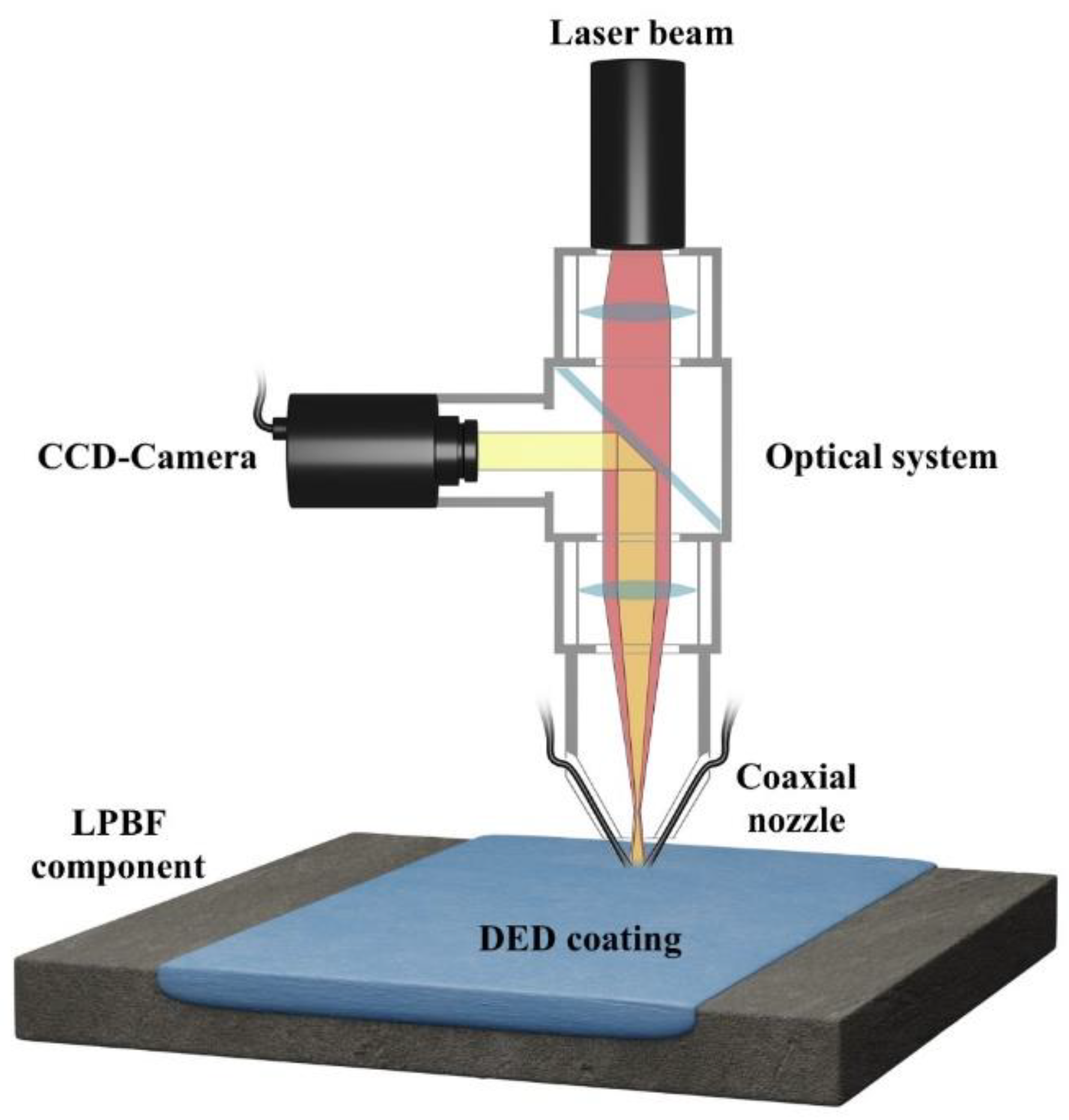
2.1. DED Coating and Monitoring Setup

The coatings were realized by means of a DED technique that implement a prototype Cartesian system equipped with a fiber laser (YLS, λ = 1070 nm and maximum laser power of 4 kW). The beam was delivered by a 100-μm diameter process fiber, and then passed through a motorized optical collimator (focal length = 100 mm) and a focusing lens (focal length = 200 mm). The metal powder is supplied to the process thanks to a carrier gas flow (argon) that conveys it from the powder feeding system to a coaxial nozzle.
In addition, the process was monitored through a CCD camera (IDS UI-6230RE-M-GL PoE Rev.3, Obersulm, Germany), installed in the deposition head, which is used both for positioning procedure and for in-process analysis of the shape of the melt pool. Figure 1 depicts the DED coating process scheme and the monitoring system employed.

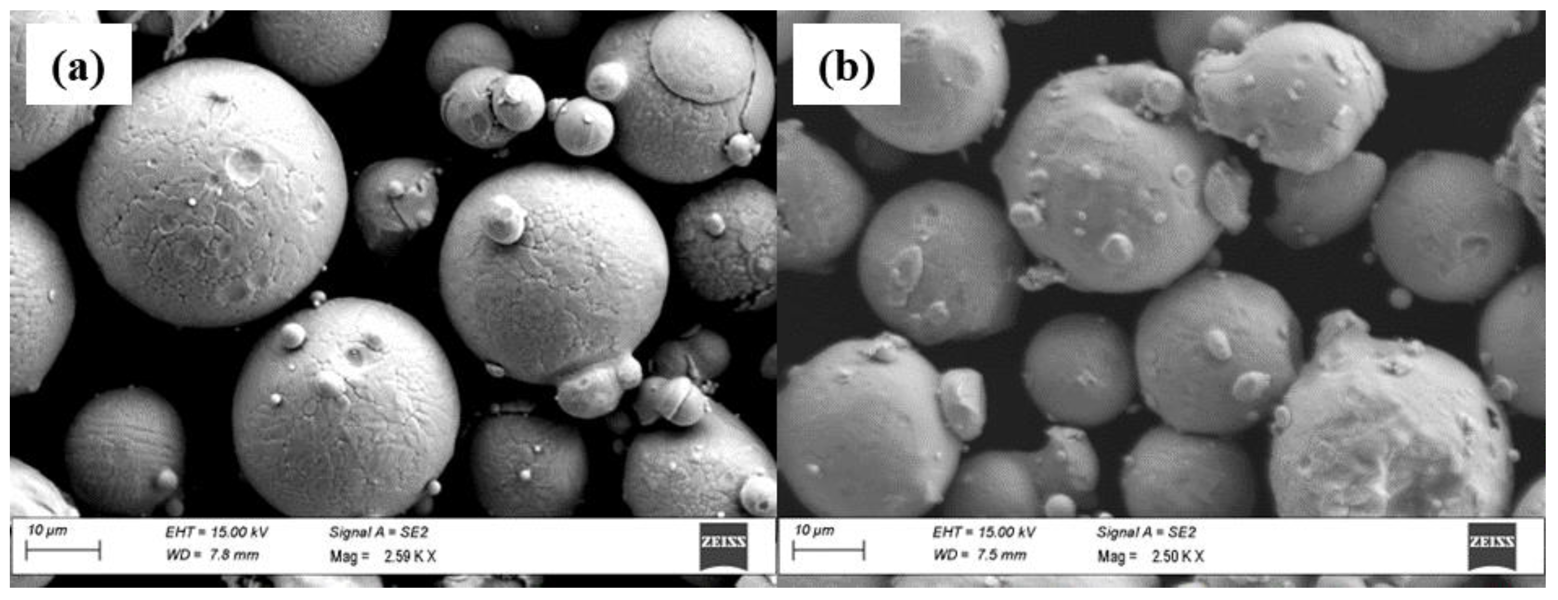
2.2. Materials and Heat Treatment

The material used for the coating was a commercial spherical powder of 18Ni (300) maraging steel, as can be seen in Figure 2a. AISI 316L stainless steel plates, fabricated by the L-PBF process, were used as substrates. Figure 2b shows the AISI 316L spherical powder used to manufacture the L-PBF substrates. The size and chemical distribution of the metal powders used for the coating and substrate are shown in Table 1 (data certified by the manufacturers). The 18Ni (300) gas atomized maraging steel powder was produced and certified by GE Additive (Lichtenfels, Germany), and the AISI 316L gas atomized stainless steel powder was produced and certified by Mimete Metal Powders (Biassono, Italy). The substrates, shown in Figure 3, were fabricated by L-PBF with a set of process parameters optimized in previous works [5,21]. The resulting coatings were subjected to a subsequent two-step heat treatment based on the literature [1,15,22]: solution annealing (815 °C for 1 h, air-cooled) followed by aging heat treatment (480 °C for 5 h) to improve the mechanical properties.

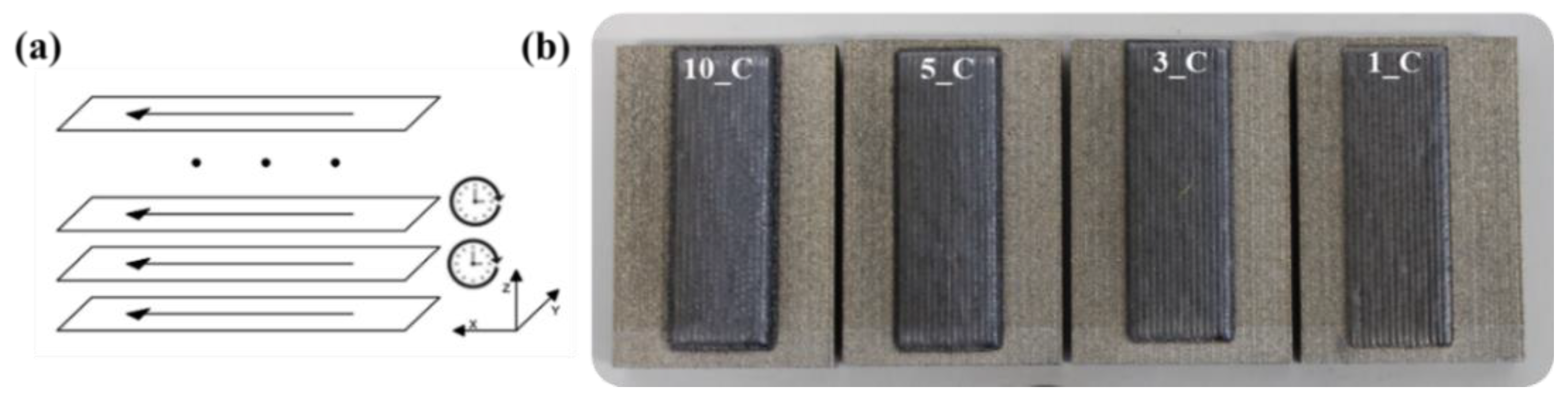
2.3. Experimental Details

The DED coatings were realized with a different number of layers (1, 3, 5, and 10 layers), as shown in Figure 4b. These were deposited on four L-PBF substrates adopting a one-way deposition strategy and 30 s of dwelling time between every single track and between every layer (see Figure 4a). The specimen identification follows the nomenclature: N_C and N_T with N = number of layers, C = as-coated, and T = treated.
The process parameters for the deposition of coatings were: laser power = 400 W, spot diameter = 1.5 mm, scanning speed = 1000 mm/min, powder feed rate = 5.0 g/min, carrier gas flow rate = 10 L/min, hatch distance along y-direction = 0.906 mm, and step height along z-direction = 0.096 mm. These process parameters were obtained after preliminary single-track tests performed on L-PBF substrates and subsequent geometrical characterization. The preliminary tests are based on a Taguchi orthogonal L36 experimental plan and are listed in Table 2. The methodology followed to identify the optimal process parameters, which resulted in a high-quality coating and was described in detail in the aforementioned work [5].

2.4. Analysis and Characterization Procedure

The quality of the manufactured coatings was assessed in-process through the implementation of an optical monitoring system and an image-analysis methodology. In detail, the manufacturing process was monitored by means of a CCD camera located in the deposition head. Thanks to a dichroic mirror, this equipment allowed the observation and monitoring of the melt pool morphology, coaxially with respect to the laser beam (see Figure 1). The camera was set up with an acquisition frequency of 40 fps and a resolution of 1024 × 768 pixels (pixel size around 5 μm). For each video, the frames related to the manufacturing process were extracted and the melt pool evolution was examined by applying an image-processing algorithm.
Concerning the image-analysis methodology, the workflow has been set of three steps: video capture, frame extraction, and image processing. The latter is performed in the MATLAB environment (Release 2021, Cleve Moler, Albuquerque, NM, USA) by using an image segmentation algorithm called the region-based active contour (R-BAC).
Furthermore, the coatings were carefully prepared through cutting, embedding, and polishing steps, followed by a chemical etching (Etchant: 6 mL acetic acid, 10 mL hydrochloric acid, 1–2 g picric acid, and 100 mL ethyl alcohol) to identify the optimal set of process parameters and to investigate their final quality in terms of geometrical characteristics, microstructural properties, and chemical composition. Microstructural analyses were conducted by means of the Nikon Eclipse MA200 (Nikon Corporation, Tokyo, Japan) inverted optical microscope and the Zeiss Sigma 300 VP (Carl Zeiss Microscopy, New York, NY, USA) scanning electron microscope, combined with EDX spectroscopy (Carl Zeiss Microscopy, New York, NY, USA). Finally, low-force Vickers hardness tests were performed, on both the as-coated and heat-treated coatings by using the HMV-G by Shimadzu hardness tester (Shimadzu, Kyoto, Japan), according to the ISO 6507-1 test method (0.3 kgf of load and 10 s of dwelling time).

3. Results and Discussion

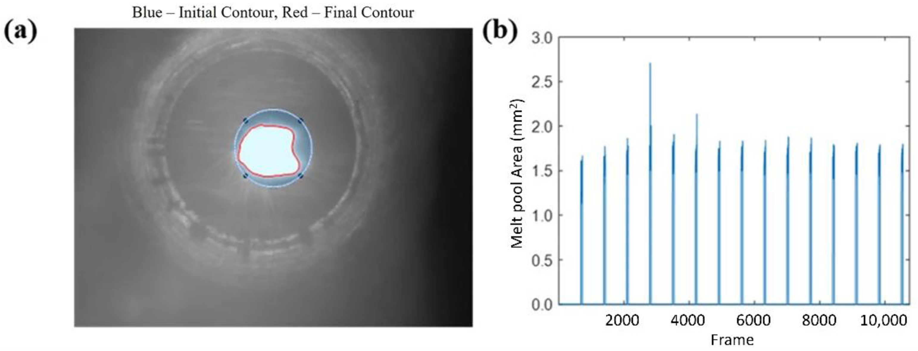
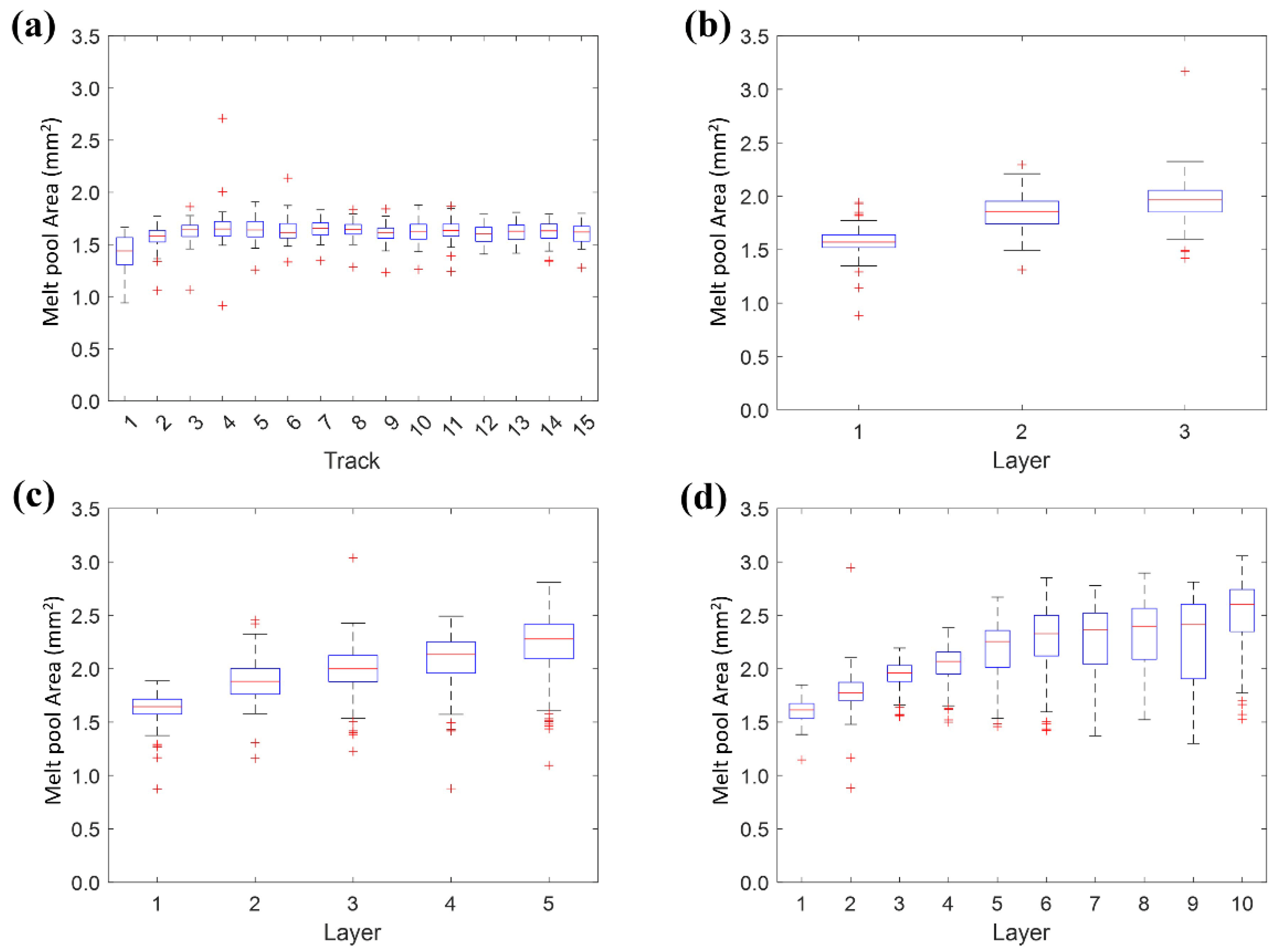
3.1. Optical Monitoring of the DED Process

The R-BAC is an iterative method capable of analyzing the image brightness gradient in order to define regions with the same properties. The algorithm starts from an initial mask in the form of a closed curve, which iteratively changes its shape and size adapting to the image brightness, driven by the minimization of an energy function (see Figure 5a). This algorithm has already proved its effectiveness for the study of the melt pool during the laser deposition process, both to determine the evolution of its size and to identify potential production defects [23]. Figure 5b shows the result of the calculation of the melt pool area by means of the R-BAC algorithm on the 11,000 frames extracted from the video recorded during the manufacture of specimen 1_C. The algorithm is capable of activating during the laser deposition process while returning null values during dwelling times between tracks, when the laser is turned off.
Figure 6a shows the variation of the melt pool area during the fabrication of the layer. It can be seen from the plot how the area has an average size of 1.42 mm2 in the first track, which grows and stabilizes around the value of 1.65 mm2 from the second track onward of the 15 traces that make up the layer. In addition, it is noted that the reduced dimension of the box plot height indicates the low variability of the values and thus the good stability of the coating process. The red crosses represent the outliers of the analysis, often attributable to defects in the DED process caused by fluctuations in powder flow. The proximity of the outliers to the average values is another factor that characterizes the stability of the deposition process.
Figure 6b–d show the trend assumed by the melt pool during the construction of multilayer components 3_C, 5_C, and 10_C, respectively. As previously shown, the low divergence of the calculated value during the deposition of single traces (mainly due to the implementation of the dwelling times between each track) allowed the reliable estimation of the average melt pool area for each layer. These summary values of the 15 tracks constituting each layer, showed a rather low range of variation with the sporadic presence of outliers. This was another corroboration of the stability of the deposition process even in the production of multilayer coatings.
Analyzing the graphs, it was easy to discern the increasing trend of the melt pool area as the number of layers increased. This result can be attributed to a change in heat transfer conditions during the process [24]. Specifically, in the first layer, the deposition on a substrate at room temperature provided the greatest heat dissipation and the generation of a melt pool area smaller than the subsequent layers. Furthermore, the gradual increase of the melt pool area was caused by the difficulty of dissipating the heat produced during the laser deposition and its accumulation in the coating area. In this way, there was an increase in the average temperature of each layer with the consequential increase in the melt pool area, even though the same process parameters were used.

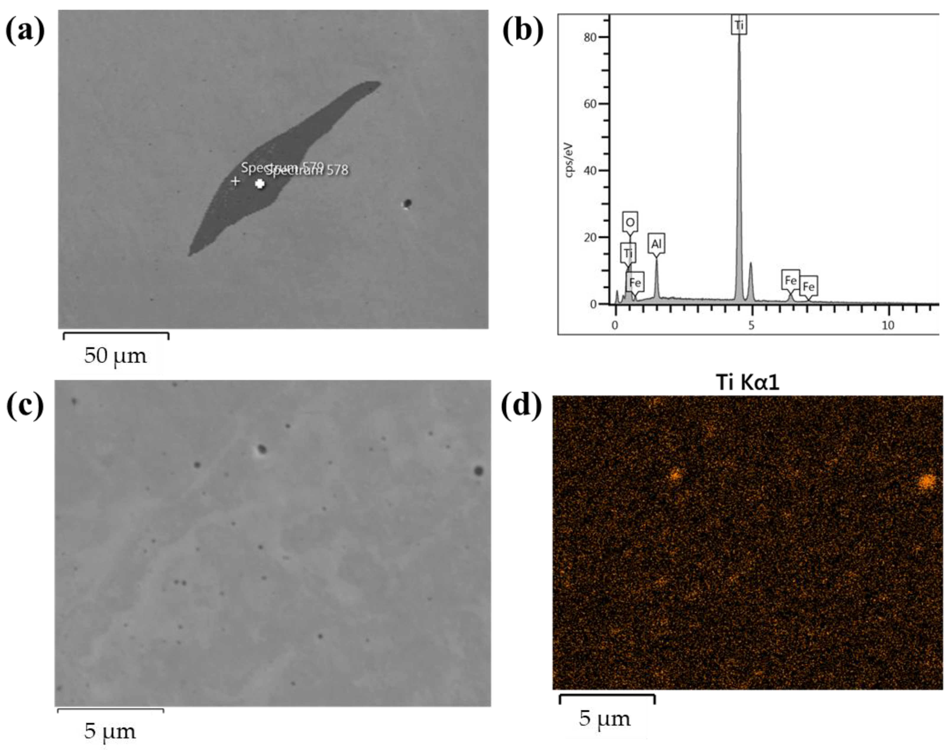
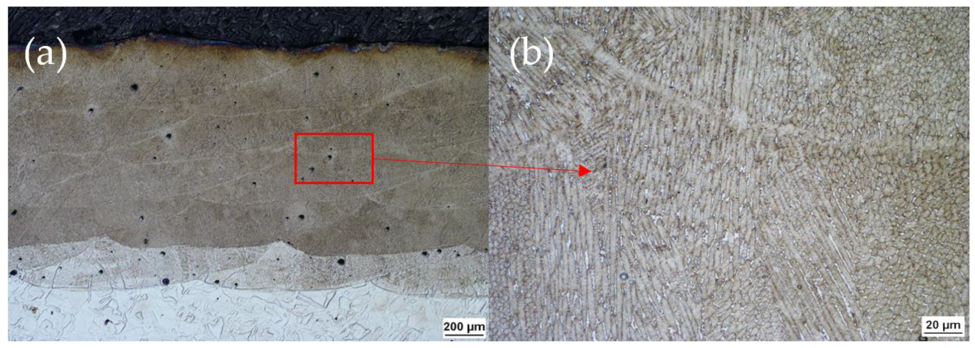
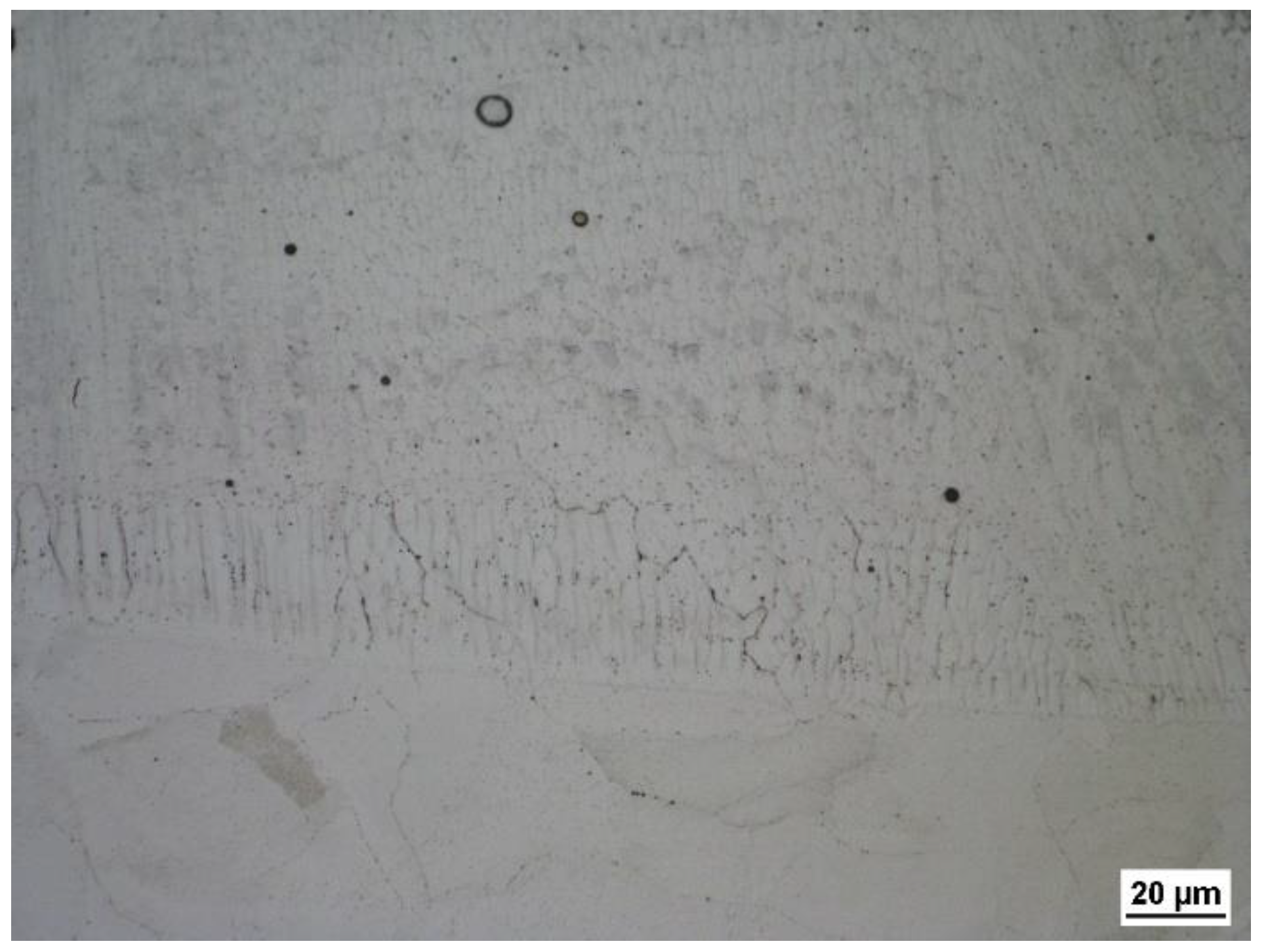
3.2. Microscopic Examination and Chemical Analysis

The SEM analysis showed that in as-coated specimens are present precipitates with moderate dimensions constituted by a Ti-rich phase (Figure 7a,b) because the content of this element in the powder is 1.15 wt. % (Table 1). In contrast, in the heat-treated specimens, this category of precipitates first dissolved in the metal matrix during the heating stage and then reprecipitated during the cooling stage. This segregation mechanism is characterized by more finely dispersed precipitates, most of which are not observable under optical microscopy. Only a small fraction of slightly coarser spherical particles is visible, as can be seen in Figure 7c,d. The precipitation of small-size Ti-rich particles leads to an improvement of the hardness value in the heat-treated specimens [25].
Chemical analysis was conducted by the use of EDX microprobe. It has been observed that the chromium tended to transfer from the parent metal (substrate) to the first layer (Figure 8). The high chromium concentration in the first layer can be explained by the Marangoni convection [26] during the deposition process. Therefore, the Marangoni convection effect and the diffusion of elements at the interface between the two materials facilitated the formation of a Cr-rich region in the first layer of the coating (see Figure 8b,d). In addition, it can be seen from Figure 8c,e that Co also exhibits a transient distribution between coating and substrate. The previous outcomes result in excellent adhesion achieved at the interface. These phenomena were present on both as-coated and heat-treated specimens, demonstrating that aging treatment does not influence Cr and Co distributions.
Optical micrographs of the specimens before the chemical etch disclosed the presence of spherical discontinuities with diameters in the range of 10–30 μm (Figure 9), which can be considered acceptable in this type of manufacturing process [27].
Specimens were chemically etched in order to reveal the microstructure of the material. An interesting result concerns the difference between the microstructure in the first layer and in the successive layers of the heat-treated specimens. Micrographs show that Cr dispersion affected negatively the treatability of the material. The martensitic transformation that occurred by precipitation of intermetallic compounds was clearly visible in all the coating layers except in the first one (Figure 10). Only very few retained austenite areas were visible. It was also possible to observe that the metallurgical interface was regular and free of significant defects (see Figure 10 and Figure 11). Discontinuities like lack of fusion and adhesion, cracks, delamination or significant porosity were not observed, and intermetallic precipitates were also absent in all samples. Furthermore, Figure 11 shows the presence of a fusion line in the interface zone between substrate and coating instead of an extended heat-affected zone (HAZ). This is due to the localized heating and fast cooling distinctive of the directed energy deposition process.
Figure 12 reports the microstructure of the 1_T specimen that shows only a partial transformation probably due to the inhibitor effect of Cr presence. In fact, it is well known that the Cr effect on iron-based materials is to lower martensite start (Ms) temperature promoting the austenite formation during the solidification step [28] and hindering martensitic transformation in the aging treatment step. Moreover, the aggregation of a considerable amount of Cr in the first layer enhanced the austenite stability in this region due to the dissolution of Cr itself in it, forming Fe-Cr austenite.
The AISI 316L substrate resulted also affected by the heat treatment (Figure 13). In fact, although in the as-coated condition the laser traces of the L-PBF process were clearly visible, they disappeared in the heat-treated substrate, because of the recrystallization that occurred during the heat treatment.

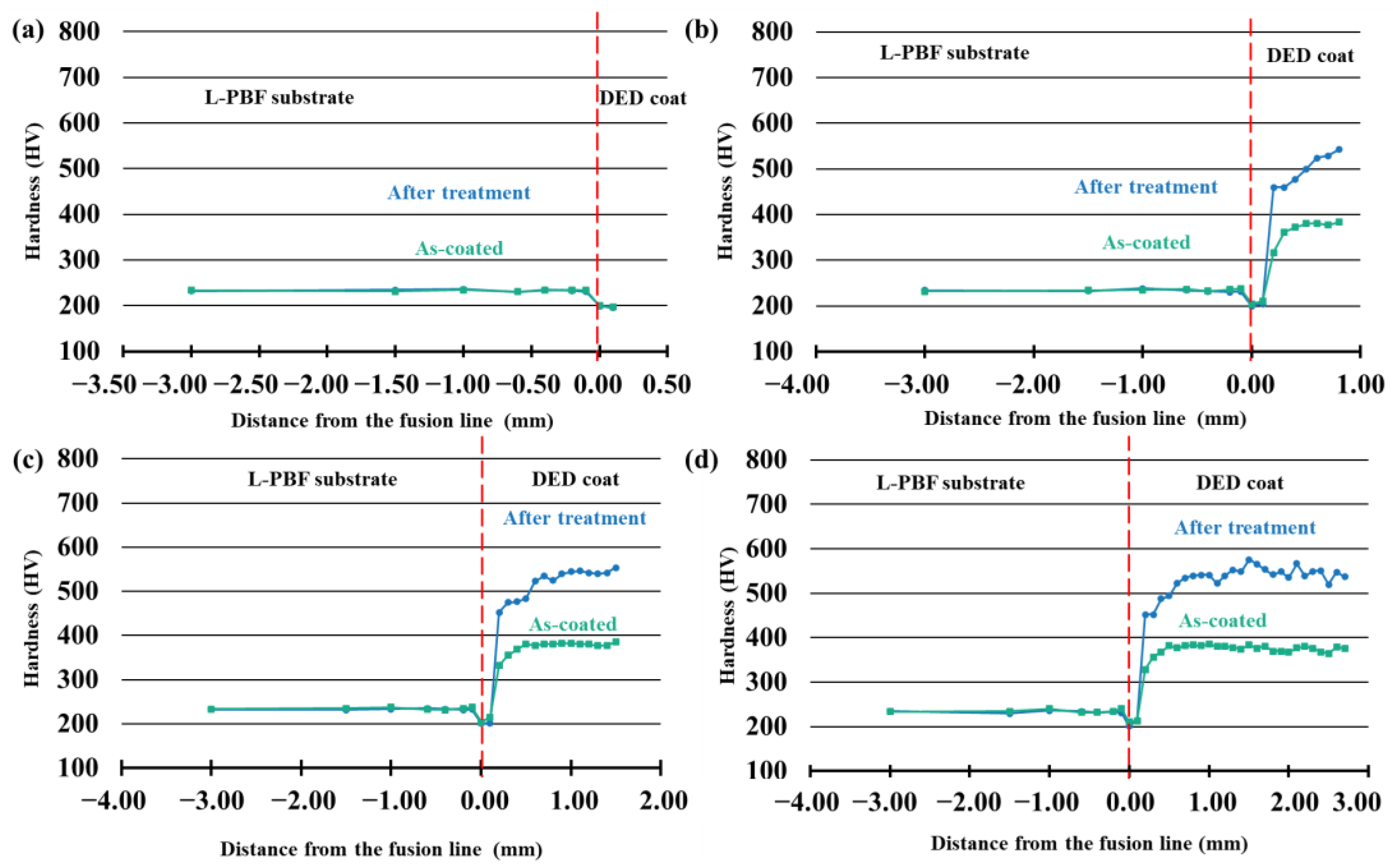
3.3. Low-Force Vickers Hardness Test

The Vickers hardness test was performed to determine the effects of aging heat treatment on the maraging coating. All the samples were tested along the coating growth direction. Figure 14 shows that the hardness trend appears superimposable between the different samples. In fact, in all case studies, the as-coated sample hardness was in the 350 ÷ 390 HV range, which was consistent with a solution annealed state of the 18Ni (300) maraging steel [29]. The samples subjected to aging treatment exhibited higher hardness values in all the deposited layers except for the first one. In fact, the hardness difference was ~200 HV, due to the martensitic microstructure of the treated coating. Furthermore, the hardness decreases to 200 HV at the substrate-coating interface and at the first layer, starting from an average value of 235 HV in the L-PBF component. For this reason, a single-layer coating should not be recommended (see Figure 14a).
As observed during the microscopic examination, the first layer of each coating had a different behavior also in mechanical properties. This aspect was attributable to the different chemical compositions generated by the mixture of substrate metal and maraging steel.

4. Conclusions

In this work, a directed energy deposition coating, using 18 Ni(300) maraging steel powder and subsequent heat treatment, was successfully performed on AISI 316L components realized by laser-powder bed fusion. Below the main results are listed.
  • The stability of the coating process was verified through the support of an optical monitoring methodology (CCD camera plus real-time image processing), which allowed the observation of the melt pool in real time.
  • The hardness decreased to 200 HV at the substrate-coating interface and the first layer, starting from an average value of 235 HV in the L-PBF component. Coatings made with 3, 5, and 10 layers have a hardness equal to 375 HV (as-coated) and 580 HV (after treatment), according to the scientific literature.
  • The hardness results are strongly related to the microstructural properties achieved by the as-coated and after-treatment coating. In particular, the microstructure obtained after solution annealing and age-hardening treatment is lath martensite. The aging involves the precipitation of nickel-rich intermetallic compounds in the lath martensitic structure, leading to a strengthening of the hardness by precipitation.
The results obtained from the work ascertained the feasibility of producing a component with an AISI 316L core, obtained by the L-PBF process, and coated with the 18Ni (300) maraging tool steel by means of the DED technique. In fact, the coatings obtained, in the cases of three-layer, five-layer and 10-layer coatings, were found to be highly performant as they had a metallurgical interface free of defects (discontinuities such as lack of fusion and adhesion, cracks, or delamination) and negligible porosity. Finally, this study aims to contribute to the reduction of tool and die manufacturing costs while still allowing for high surface mechanical properties of the final component, exploiting the strengths of the two AM technologies employed.

Author Contributions

Conceptualization, V.E. and P.P.; methodology, V.E. and P.P.; software, V.E., P.P., and M.M.; validation, V.E., A.A., and S.L.C.; formal analysis, V.E. and P.P.; investigation, V.E. and P.P.; resources, A.A. and S.L.C.; data curation, V.E., P.P., and M.M.; writing—original draft preparation, V.E. and P.P.; writing—review and editing, V.E., M.M., A.A., and S.L.C.; visualization, V.E., P.P., A.A., and S.L.C.; supervision, A.A. and S.L.C.; project administration, S.L.C.; funding acquisition, S.L.C. All authors have read and agreed to the published version of the manuscript.

Funding

This research received no external funding.

Institutional Review Board Statement

Not applicable.

Informed Consent Statement

Not applicable.

Data Availability Statement

The data presented in this study are available on request from the corresponding author.

Conflicts of Interest

The authors declare no conflict of interest.

References

  1. Samei, J.; Asgari, H.; Pelligra, C.; Sanjari, M.; Salavati, S.; Shahriari, A.; Amirmaleki, M.; Jahanbakht, M.; Hadadzadeh, A.; Amirkhiz, B.S.; et al. A Hybrid Additively Manufactured Martensitic-Maraging Stainless Steel with Superior Strength and Corrosion Resistance for Plastic Injection Molding Dies. Addit. Manuf. 2021, 45, 102068. [Google Scholar] [CrossRef]
  2. Oh, W.J.; Lee, W.J.; Kim, M.S.; Jeon, J.B.; Shim, D.S. Repairing Additive-Manufactured 316L Stainless Steel Using Direct Energy Deposition. Opt. Laser Technol. 2019, 117, 6–17. [Google Scholar] [CrossRef]
  3. Lewis, S.R.; Lewis, R.; Fletcher, D.I. Assessment of Laser Cladding as an Option for Repairing/Enhancing Rails. Wear 2015, 330–331, 581–591. [Google Scholar] [CrossRef]
  4. Wei, S.; Wang, G.; Wang, L.; Rong, Y. Characteristics of Microstructure and Stresses and Their Effects on Interfacial Fracture Behavior for Laser-Deposited Maraging Steel. Mater. Des. 2018, 137, 56–67. [Google Scholar] [CrossRef]
  5. Errico, V.; Fusco, A.; Campanelli, S.L. Effect of DED Coating and DED + Laser Scanning on Surface Performance of L-PBF Stainless Steel Parts. Surf. Coatings Technol. 2022, 429, 127965. [Google Scholar] [CrossRef]
  6. Feenstra, D.R.; Banerjee, R.; Fraser, H.L.; Huang, A.; Molotnikov, A.; Birbilis, N. Critical Review of the State of the Art in Multi-Material Fabrication via Directed Energy Deposition. Curr. Opin. Solid State Mater. Sci. 2021, 25, 100924. [Google Scholar] [CrossRef]
  7. Mei, X.; Wang, X.; Peng, Y.; Gu, H.; Zhong, G.; Yang, S. Interfacial Characterization and Mechanical Properties of 316L Stainless Steel/Inconel 718 Manufactured by Selective Laser Melting. Mater. Sci. Eng. A 2019, 758, 185–191. [Google Scholar] [CrossRef]
  8. Chen, J.; Yang, Y.; Song, C.; Zhang, M.; Wu, S.; Wang, D. Interfacial Microstructure and Mechanical Properties of 316L /CuSn10 Multi-Material Bimetallic Structure Fabricated by Selective Laser Melting. Mater. Sci. Eng. A 2019, 752, 75–85. [Google Scholar] [CrossRef]
  9. Saleh, B.; Jiang, J.; Fathi, R.; Al-hababi, T.; Xu, Q.; Wang, L.; Song, D.; Ma, A. 30 Years of Functionally Graded Materials: An Overview of Manufacturing Methods, Applications and Future Challenges. Compos. Part B 2020, 201, 108376. [Google Scholar] [CrossRef]
  10. Kunimine, T.; Miyazaki, R.; Yamashita, Y.; Funada, Y. Effects of Laser-Beam Defocus on Microstructural Features of Compositionally Graded WC/Co-Alloy Composites Additively Manufactured by Multi-Beam Laser Directed Energy Deposition. Sci. Rep. 2020, 10, 8975. [Google Scholar] [CrossRef]
  11. Feenstra, D.R.; Molotnikov, A.; Birbilis, N. Effect of Energy Density on the Interface Evolution of Stainless Steel 316L Deposited upon INC 625 via Directed Energy Deposition. J. Mater. Sci. 2020, 55, 13314–13328. [Google Scholar] [CrossRef]
  12. Hasanov, S.; Alkunte, S.; Rajeshirke, M.; Gupta, A.; Huseynov, O.; Fidan, I.; Alifui-Segbaya, F.; Rennie, A. Review on Additive Manufacturing of Multi-Material Parts: Progress and Challenges. J. Manuf. Mater. Process. 2021, 6, 4. [Google Scholar] [CrossRef]
  13. Ben-Artzy, A.; Reichardt, A.; Borgonia, J.P.; Dillon, R.P.; McEnerney, B.; Shapiro, A.A.; Hosemann, P. Compositionally Graded SS316 to C300 Maraging Steel Using Additive Manufacturing. Mater. Des. 2021, 201, 109500. [Google Scholar] [CrossRef]
  14. Aydogan, B.; Sahasrabudhe, H. Enabling Multi-Material Structures of Co-Based Superalloy Using Laser Directed Energy Deposition Additive Manufacturing. Metals 2021, 11, 1717. [Google Scholar] [CrossRef]
  15. Demir, A.G.; Kim, J.; Caltanissetta, F.; Hart, A.J.; Tasan, C.C.; Previtali, B.; Colosimo, B.M. Enabling Multi-Material Gradient Structure in Laser Powder Bed Fusion. J. Mater. Process. Technol. 2022, 301, 117439. [Google Scholar] [CrossRef]
  16. Wei, C.; Zhang, Z.; Cheng, D.; Sun, Z.; Zhu, M.; Li, L. An Overview of Laser-Based Multiple Metallic Material Additive Manufacturing: From Macro- to Micro-Scales. Int. J. Extrem. Manuf. 2021, 3, 012003. [Google Scholar] [CrossRef]
  17. Félix-Martínez, C.; Ibarra-Medina, J.; Fernández-Benavides, D.A.; Cáceres-Díaz, L.A.; Alvarado-Orozco, J.M. Effect of the Parametric Optimization and Heat-Treatment on the 18Ni-300 Maraging Steel Microstructural Properties Manufactured by Directed Energy Deposition. Int. J. Adv. Manuf. Technol. 2021, 115, 3999–4020. [Google Scholar] [CrossRef]
  18. Blakey-Milner, B.; Gradl, P.; Snedden, G.; Brooks, M.; Pitot, J.; Lopez, E.; Leary, M.; Berto, F.; du Plessis, A. Metal Additive Manufacturing in Aerospace: A Review. Mater. Des. 2021, 209, 110008. [Google Scholar] [CrossRef]
  19. Jiménez, M.; Romero, L.; Domínguez, I.A.; del Espinosa, M.M.; Domínguez, M. Additive Manufacturing Technologies: An Overview about 3D Printing Methods and Future Prospects. Complexity 2019, 2019, 1–30. [Google Scholar] [CrossRef] [Green Version]
  20. Sarvankar, S.G.; Yewale, S.N. Additive Manufacturing in Automobile Industry. Int. J. Res. Aeronaut. Mech. Eng. 2019, 7, 1–10. [Google Scholar]
  21. Guerra, M.G.; Errico, V.; Fusco, A.; Lavecchia, F.; Campanelli, S.L.; Galantucci, L.M. High Resolution-Optical Tomography for in-Process Layerwise Monitoring of a Laser-Powder Bed Fusion Technology. Addit. Manuf. 2022, 55, 102850. [Google Scholar] [CrossRef]
  22. Campanelli, S.L.; Contuzzi, N.; Posa, P.; Angelastro, A. Study of the Aging Treatment on Selective Laser Melted Maraging 300 Steel. Mater. Res. Express 2019, 6, 66580. [Google Scholar] [CrossRef]
  23. Errico, V.; Campanelli, S.L.; Angelastro, A.; Dassisti, M.; Mazzarisi, M.; Bonserio, C. Coaxial Monitoring of Aisi 316l Thin Walls Fabricated by Direct Metal Laser Deposition. Materials 2021, 14, 1–17. [Google Scholar] [CrossRef] [PubMed]
  24. Akbari, M.; Kovacevic, R. Closed Loop Control of Melt Pool Width in Robotized Laser Powder–Directed Energy Deposition Process. Int. J. Adv. Manuf. Technol. 2019, 104, 2887–2898. [Google Scholar] [CrossRef]
  25. Niu, M.; Zhou, G.; Wang, W.; Shahzad, M.B.; Shan, Y.; Yang, K. Precipitate Evolution and Strengthening Behavior during Aging Process in a 2.5 GPa Grade Maraging Steel. Acta Mater. 2019, 179, 296–307. [Google Scholar] [CrossRef]
  26. Jiang, Y.; Cheng, Y.; Zhang, X.; Yang, J.; Yang, X.; Cheng, Z. Simulation and Experimental Investigations on the Effect of Marangoni Convection on Thermal Field during Laser Cladding Process. Optik 2020, 203, 164044. [Google Scholar] [CrossRef]
  27. Bidare, P.; Jiménez, A.; Hassanin, H.; Essa, K. Porosity, Cracks, and Mechanical Properties of Additively Manufactured Tooling Alloys: A Review. Adv. Manuf. 2021, 10, 175–204. [Google Scholar] [CrossRef]
  28. ASM International Handbook Committee. ASM Handbook (vol. 4: Heat Treating); ASM International: Geauga County, OH, USA, 1991; pp. 518–548. [Google Scholar]
  29. Simson, T.; Koch, J.; Rosenthal, J.; Kepka, M.; Zetek, M.; Zetková, I.; Wolf, G.; Tomčík, P.; Kulhánek, J. Mechanical Properties of 18Ni-300 Maraging Steel Manufactured by LPBF. Procedia Struct. Integr. 2019, 17, 843–849. [Google Scholar] [CrossRef]
Figure 1. Schematic overview of the directed energy deposition system and monitoring setup used for coating.
Metals 12 01669 g001
Figure 2. Metal powder morphology displayed by scanning electron microscopy. (a) 18Ni (300)—coating, (b) AISI 316L—substrate.
Metals 12 01669 g002
Figure 3. AISI 316L substrates manufactured by using L-PBF technology.
Metals 12 01669 g003
Figure 4. (a) Schematic representation of the deposition strategy and (b) DED coatings on L-PBF substrates.
Metals 12 01669 g004
Figure 5. (a) Initial mask (blue) and final contour (red) of R-BAC algorithm and (b) Melt pool area of specimen 1_C.
Metals 12 01669 g005
Figure 6. Trend of the melt pool area. (a) Sample 1_C, (b) Sample 3_C, (c) Sample 5_C, (d) Sample 10_C (c).
Metals 12 01669 g006
Figure 7. SEM analysis of precipitated particles in the as-coated specimen. (a) SEM image of precipitated particles and (b) spectral distribution of chemical species, Ti particles dispersion after heat treatment, (c) SEM image of Ti particles dispersion and (d) EDX scan map of Ti particles distribution.
Metals 12 01669 g007
Figure 8. Chemical composition assessed by EDX microanalysis of Cr and Co concentration in 3_T specimen, (a) SEM image of coating and substrate zone, (b) EDX line scan of Cr distribution, (c) EDX line scan of Co distribution, (d) EDX scan map of Cr distribution, (e) EDX scan map of Co distribution.
Metals 12 01669 g008
Figure 9. Optical micrograph of 5_C specimen showing porosity.
Metals 12 01669 g009
Figure 10. 5_T specimen showing (a) different microstructures in the coating, between the first and subsequent layers, and (b) complete martensitic microstructure in the upper layers.
Metals 12 01669 g010
Figure 11. Optical micrograph of the interface zone in specimen 5_T at 200× magnification.
Metals 12 01669 g011
Figure 12. 1_T specimen microstructure showing the incomplete martensitic transformation.
Metals 12 01669 g012
Figure 13. Substrate microstructure in (a) as-coated condition and (b) heat-treated condition.
Metals 12 01669 g013
Figure 14. Hardness trends in as-coated and after treatment samples: (a) 1-layer, (b) 3-layer, (c) 5-layer, and (d) 10-layer.
Metals 12 01669 g014
Table 1. Powder size and chemical composition (wt. %) according to the test method: ASTM E2594-20.
Powder MaterialRange of Particle Size (μm)CrNiCMnSiMoCoTiFe
AISI 316L (substrate)15–4517.811.40.0121.40.452.31--Bal.
18Ni (300) (coating)15–53-18.70.02--3.7310.41.15Bal.
Table 2. Taguchi orthogonal L36 preliminary single-track experimental plan.
Process ParameterUnitsFactor Levels
123
Laser powerW400600-
Spot diametermm1.52.02.5
Scanning speedmm/min100015002000
Powder feed rateg/min2.55.0-
Carrier gas flow rateL/min1015-
Publisher’s Note: MDPI stays neutral with regard to jurisdictional claims in published maps and institutional affiliations.

