Abstract
Rate theory models have been developed for the swelling and He-embrittlement of austenitic stainless steels and Ni-alloys in nuclear reactors. The models illustrate how microstructure evolution during irradiation affects the rate of change of mechanical properties and the dimensional stability. He-stabilised cavity accumulation on grain boundaries, which causes brittle failure at low stresses and strains known as He-embrittlement, is shown to be strongly dependent on the irradiation temperature and the rate of production of Frenkel pairs and He atoms. The results show that the accumulation of cavities on grain boundaries falls into two regimes: (i) that dictated by matrix bubble swelling at low temperatures; and (ii) that dictated by matrix void swelling at high temperatures.
1. Introduction
Austenitic stainless steels and nickel alloys are used for core internal structures in sodium-cooled fast reactors (SFRs), Light Water Reactors (LWRs) and Heavy Water Reactors (HWRs) because of their high strength and retained toughness after irradiation to moderate doses., i.e., before the onset of void swelling. According to the definition of Bhattacharya and Zinkle [1], a cavity that is empty or filled with gas below equilibrium pressure is called a void, while a pressurized cavity (near or above thermal equilibrium conditions) is a bubble. An equilibrium bubble is one where, in the absence of irradiation at a given temperature and bubble size, the work done by the pressure when a bubble expands is balanced by the increase in surface energy that would result.
For fast reactors, operating temperatures vary from 400 °C to 550 °C for the internal structures, and up to 650 °C for the fuel cladding. The internal structures of the LWRs and HWRs operate at temperatures between about 200 °C and 320 °C although some parts can be hotter (more than 400 °C) because of localised nuclear heating.
Ongoing reactor operability relies on being able to understand and predict how the mechanical properties and dimensional stability of the core structural materials change over extended periods of operation. Test reactor irradiations and power reactor operating experience over more than 50 years has resulted in the accumulation of a large amount of data from which one can assess the effects of irradiation on swelling and mechanical properties.
The strength and ductility of austenitic alloy components, such as Inconel X-750, 304, 316 and 347 stainless steels, are sensitive to the accumulation of He-stabilised cavities on grain boundaries. The accumulation, measured as grain boundary area coverage, can be predicted from rate theory, and is intimately related to the amount of swelling due to cavities in the grain interior. He atoms are formed from α-particles. They have a high mobility (0.14 eV), similar to self-interstitial atoms [2], and have a strong affinity for vacancies, with a dissociation energy of 2.4 eV [3]. Unlike self-interstitial atoms, however, the He atoms are not annihilated but trapped when they interact with vacancies. The He-V complex is still mobile, albeit with a migration energy of 0.81 eV [3]. The complexities of He interactions with point defects regarding migration and the effect of binding with various clusters has been reviewed in various publications, notably [4,5,6]. Without knowing what sink biases to apply for the He-V complexes, and what percentage of the He atom migration to larger sinks is in the form of interstitial He or He-V complexes, we have chosen to make the simplifying assumption that the net He migration to all sinks (including single vacancies) is by a mix of interstitial He and He-V complexes, which may involve one or two vacancies [6]. The evolution of the cavity clusters is then governed by the arrival of He atoms migrating either as an interstitial or as a He-V complex. To this end we have chosen measured values over theoretical values for migration energies [2,3]. It should be noted, however, that the choice of He migration energy does not affect the results. Other than the enhanced recombination of interstitials and vacancies at low temperatures, the fluxes of point defects to various sinks are dependent on their rate of production rather than the speed with which they migrate to the sinks.
At low temperatures (<300 °C), swelling is limited to that dictated by the ratio of helium atoms to vacancies (He/V) in bubbles [7,8,9,10,11,12,13,14,15]. Equilibrium bubbles only grow by absorbing He and should remain in a stable state, even after the irradiation ceases, if maintained at the same temperature. At higher irradiation temperatures (>400 °C), the He-stabilised cavities can grow by the bias-driven accumulation of vacancies, which leads to accelerated swelling, i.e., more than that expected for equilibrium bubbles. Cavities, or voids, that have evolved by the non-equilibrium (bias-driven) accumulation of vacancies are thermally unstable and will shrink if the irradiation stops while maintaining the same temperature, i.e., they are non-equilibrium. Equilibrium bubbles can grow by absorbing thermal vacancies if the material is heated to a higher temperature after irradiation [15,16,17]. He-stabilised cavities cannot easily be removed by thermal means because of the very strong binding of the He atom with vacancies [3].
Rate theory models can successfully predict swelling in the bias-driven growth regime because the net flow of vacancy point defects to cavity sinks is dictated by the biased elastic interaction between interstitial point defects and dislocation sinks [16,17]. Rate theory can accurately predict swelling when the temperature is >400 °C and the He generation rate is low, as it is in a fast or light water reactor [17]. At low temperatures (<300 °C), in the recombination-dominated regime, the amount of swelling is determined by the He content of the material and the temperature, which dictates the He/V ratio for equilibrium bubbles [18].
If the He generation rate is very high it is conceivable that bubbles could contain excessive amounts of He, i.e., above what would normally be the equilibrium state at the temperature concerned. In an irradiation environment the concentration of vacancies may still be sufficient to maintain thermal equilibrium. It is then a question of how quickly vacancies and He atoms each migrate to the bubbles. The steady-state condition, which may be close to thermal equilibrium, can be calculated using rate theory [15,16,17]. At intermediate temperatures (300–400 °C) for austenitic steels and Ni-alloys there is a transition from recombination-dominated to sink-dominated kinetics that is dependent on the microstructure and the production rate of He and Frenkel pairs [14]. In the sink-dominated regime He-stabilised cavities contain an excess of vacancies and the cavity volume is mainly determined by the rate of arrival of excess vacancies resulting in a He/V ratio that is below equilibrium values.
The calculation of the accumulation of He-stabilised cavities on boundaries is dependent on the sink strengths of the grain interior microstructure, i.e., the ability of the internal microstructure to affect the flow of point defects and He atoms to the boundaries. Any grain boundary coverage model must include the sink evolution in the grain interior as an input. As the interior microstructure evolution is directly related to swelling, the grain boundary coverage requires that the swelling is also measured or calculated.
The freely-migrating point defect (FMD) production, which is dependent on the energy distribution of primary knock-on atoms, is also required for rate theory modelling as the modelling involves calculating the diffusion of point defects to different sinks. Some authors include the diffusion of small atom clusters in the rate theory framework [15], but the convention adopted here is to consider only the mobility of single point defects for which diffusion coefficients are known and readily available [17].
In this paper we describe a rate theory model for grain boundary coverage in the bubble and void growth temperature regimes. The model for grain boundary cavity evolution is comprised of two parts: (i) determine the interior microstructure evolution (cavities and dislocations); (ii) calculate the net flow of vacancies and He atoms to the grain boundaries, thus determining area coverage. At high temperatures the cavity microstructure can be determined using a conventional rate theory model for swelling [17] given experimental input such as the cavity number density as a function of temperature [1]. For temperatures <350 °C, cluster dynamics computations are necessary to model the cavity evolution in the grain interior [15]. Alternatively, experimental data can be used. We use an empirical model for the cavity microstructure as a function of temperature based on best estimates of the mean cavity diameters and number densities from experimental observations of austenitic material irradiated at low temperatures [18]. For temperatures >350 °C rate theory is used to calculate the cavity evolution (swelling), given experimental data in the form of cavity number density [1]. An empirical model for cavity number density is used as input for the rate theory model that then provides predictions for swelling through cavity growth [17]. The measurements of the cavity sink strengths come from Inconel X-750 components irradiated in Canada Deuterium Uranium CANDU reactors [18]. In all cases, atomic displacements are represented by displacements per atom (DPA) and gas atom production is given as atomic parts per million (APPM). He-embrittlement is the primary focus although hydrogen may also be important, especially at very low temperatures. Even though mechanical testing is often carried out at ambient temperatures, without strong evidence linking hydrogen production with embrittlement in the cases being considered, hydrogen effects, which are more esoteric than He-effects, are therefore not considered. The DPA and He production can be determined from the applicable neutron fluxes and spectra using available cross-section data [19,20,21,22,23,24].
1.1. Radiation Damage and Gas Atom Production
The calculation of the primary atomic displacement damage for given reactors is dependent on the neutron spectrum. The damage is calculated using the SPECTER code [22], which considers the reactions between neutrons of varying energies with atoms that result in atomic displacements. The most common reactions considered have been described elsewhere [22,25] and are illustrated in Figure 1.
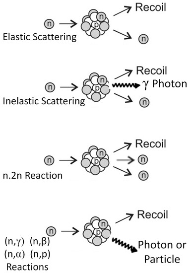
Figure 1.
Schematic illustration of the main neutron-nucleus interactions that give rise to atomic displacements.
For high dose radiation damage calculations in Ni-containing alloys the effects of transmutation of 58Ni to 59Ni must be considered as this is a process that enhances both atomic displacement and He production rates [20,21,22]. The presence of Ni can have profound effects on mechanical properties and dimensional stability of austenitic alloys, especially when subjected to a high thermal neutron flux [16,17,18,19,26,27,28].
To understand the impact of the neutron spectrum on the degradation of austenitic alloys at relatively high doses one needs to consider how Ni transmutes. The two-stage transmutations of 58Ni to 59Ni with subsequent (n,γ), (n,p) and (n,α) reactions are illustrated below [20,21,22]:
58Ni + n → 59Ni + γ
59Ni + n → 56Fe + 4He
59Ni + n → 59Co + H
59Ni + n → 60Ni + γ
The time-dependent equations giving the concentration of 59Ni and the concentration of H and He produced from the two-step reactions, 58Ni(n,γ)59Ni(n,p)59Co and 58Ni(n,γ)59Ni(n,α)56Fe, are used in conjunction with the SPECTER code to determine gas production [20,21,22]. The protons and alpha particles are deposited in the material as H and He. The production of these gaseous elements enhances the atomic displacement rate because of the additional displacement damage from the ejected particles but, more importantly, from the resulting high recoil energies [20,21].
Without considering changes in the isotopic mix due to transmutation, the atomic displacement cross-sections for common elements used in nuclear reactor materials are shown in Figure 2. Note that the displacement cross-sections for Zr are lower in the thermal energy range because Zr has a very low thermal neutron absorption cross-section. A core average spectrum and a spectrum close to the inner pressure vessel wall (the last water node) of a PWR [29] are also shown for reference. For most naturally occurring isotopes the atomic displacement damage coming from low energy neutron absorption and γ-photon emission gives rise to a low level of atomic displacements because the recoil energy is low. The largest contribution to atomic displacements in a PWR spectrum at high neutron energies is through direct elastic and inelastic collisions with neutrons although high energy absorptions, from n,p and n,α reactions producing H and He, can be important in fast reactors with a higher percentage of neutrons with energies between 5 and 10 MeV, Figure 3.
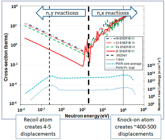
Figure 2.
Atomic displacement cross sections as a function of neutron energy (left hand scale) and neutron spectra in a PWR (right hand scale).
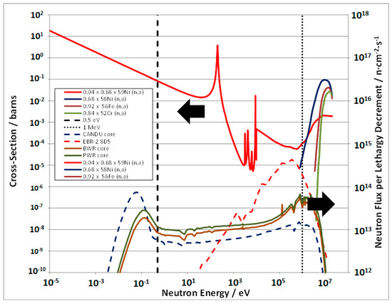
Figure 3.
Neutron spectra for PWR, BWR, CANDU and EBR-II reactors (right hand scale) and (n,α) cross-sections for the major isotopes of Ni, Fe, Cr and Zr scaled for atomic abundance (left hand scale). Also shown is the 59Ni (n,α) reaction cross section scaled for atomic abundance after 5 years operation in a CANDU core.
The n,α cross-sections for Ni, Fe, Cr and Zr shown in Figure 3 correspond to the most abundant isotopes and are scaled according to isotopic abundance. The plot illustrates the neutron energy range where these absorption reactions, which result in high recoil energies when the α-particle is emitted, become important. Not only are such reactions important for producing atomic displacement damage but they are also important for producing He, whose nucleus is the α-particle. Note the low value of the n,α cross-section for 90Zr; the lack of insoluble gasses such as He being one reason that Zr is not prone to swelling. The n,α absorption cross-section is also shown for 59Ni, which itself is produced from the low energy n,γ reaction of 58Ni. In heavy water reactors with a high thermal flux, such as the CANDU or Atucha reactors, the concentration of 59Ni can increase from zero to about 4 at % of the 58Ni after about 5 years of reactor operation. The 59Ni is then capable of producing large amounts of either He or H gas atoms over a large range of neutron energies, Figure 4. There is a concomitant increase in atomic displacement damage arising mainly from the high recoil energy associated with p and α emission. The 59Ni effect can double the atomic displacement rates in a CANDU reactor after about 5 years operation when the 59Ni is at its peak [26,27,28].
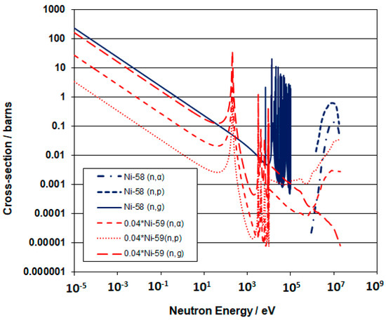
Figure 4.
59Ni and 58Ni (n, γ), (n, p) and (n, α) reaction cross sections as a function of neutron energy. The 59Ni cross sections have been scaled by a factor of 0.04, which is the 59Ni content relative to the parent 58Ni after about five years of operation in the core of a CANDU reactor.
Even without considering 59Ni, Ni can still be effective in producing He in fast reactors because the high energy n,α reaction cross-sections for naturally occurring Ni isotopes results in an order of magnitude higher He production per atom compared with other major alloying elements such as Cr and Fe. The 59Ni will become important to radiation damage production once there are significant amounts of 59Ni produced from the parent 58Ni, e.g., when the thermal neutron fluence exceeds 1021 n.cm−2, E < 0.5 eV, [19]. It is clear that the 59Ni is important for enhanced He production in the high thermal neutron fluxes of power reactors because the (n,α) cross-section is high across a large range of neutron energies (Figure 4). Many materials will produce He but most (except for boron and lithium) only have significant (n,α) cross-sections at high neutron energies. Elements such as B and Li have high (n,α) cross-sections for He production in the thermal energy range but they are present in small quantities as impurities and are therefore not included in this analysis.
Considering all the main reactions for atomic displacement damage and gas atom production, the evolution with irradiation time is non-linear because of the dependence on the production of 59Ni. This non-linearity is most extreme for the HWR cases and for high Ni content alloys such as Inconel X-750 as shown in Figure 5. The non-linearity is factored into the modelling and both displacement damage and He production rates are allowed to vary accordingly.
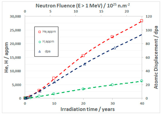
Figure 5.
Core average atomic displacements and gas production for Inconel X-750 in a CANDU-6 reactor for an average power as a function of operating time. The corresponding fast neutron fluence (E > 1 MeV) is shown on the secondary horizontal axis.
Having determined the primary atomic displacements created in collision cascades, those defects that survive spontaneous recombination are free to form clusters and migrate to various sinks in the microstructure. Although the total atomic displacements are useful for establishing empirical relationships between irradiation dose and material properties, for materials modelling it is important to know how many (what fraction) of the displaced atoms, and the corresponding vacancies, survive spontaneous recombination in the collision cascade. Of those point defects that survive, some form immobile clusters and some are free to migrate to different sinks in the microstructure. The immobile clusters are important for hardening at low doses and low temperatures and need to be assessed when studying low temperature embrittlement of ferritic pressure vessel steels. The mobile point defects, which may include small mobile clusters, are important for high temperature processes such as irradiation swelling and creep.
Rate theory calculations of creep and swelling require as input the concentration of freely migrating defects, which can be single point defects or mobile clusters. An important parameter that can be calculated using SPECTER, which provides the primary knock-on atom (PKA) spectrum and the total atomic displacement damage for each element, is the fraction of freely migrating defects.
1.2. Production of Freely-Migrating Point Defects
Radiation damage, in the form of atomic displacements, is dependent on the neutron flux spectrum and the cross-sections for various reactions. Most of the displacement damage is produced in collision cascades. Many of the Frenkel pairs recombine spontaneously and the excess left after the cascade has collapsed can be calculated using molecular dynamics [30]. Whereas the surviving fraction of Frenkel pairs produced can be high (20–40%), the fraction of defects that are mobile is lower, typically <10%. It is these mobile point defects that contribute to irradiation swelling and creep. Rate theory models that depend on point defect diffusion use the freely migrating (point) defect (FMD) production rate, which is the total primary displacement damage rate multiplied by the FMD production efficiency or fraction, as input. The FMD production efficiency (η) is a function of the cascade size, which is dependent on the energy of the primary knock-on atom (PKA) that is designated as EPKA.
Researchers using molecular dynamics simulations, e.g., Gao et al. [30], have produced expressions for the fraction of surviving defects in a collision cascade as a function of the energy of the primary recoiling atom. These surviving defects include the immobile clusters as well as the freely-migrating point defects and clusters. Others, e.g., Okamoto et al. [31], have produced data for the fraction of freely migrating point defects as a function of the energy of the primary recoiling atom based on measurements of chemical changes due to mass transport.
The Gao et al. formula for the surviving defect fraction is [30]:
where EPKA is in keV.
Whereas Okamoto et al. [31] did not provide a formula, a fit to their data [17] gives a freely migrating defect fraction as:
where EPKA is in keV.
In both cases those calculated values, which are based on an empirical fit, that are >1 are taken as being equal to 1. The FMD fractions depend on the atom and the reactor spectrum. For engineering alloying elements such as Fe, Cr and Ni in a PWR the values generated by Equation (2) are in the range of 1–10%, consistent with the values expected from the analysis of Trinkaus et al. [32]. The FMD fraction as a function of recoil energies is shown in Figure 6. The FMD expression Equation (2) is different from that reported by Kwon and Motta [33] and was chosen because it provided the best fit when comparing rate theory calculations to swelling data [17]. Also shown in Figure 6 are the experimental data for FMD production from Okamoto and Rehn [31] and Svetukhin and Tikhonchev [34]. The two datasets coincide very well giving support to the use of Equation (2) that corresponds with the fit to the data from [31].
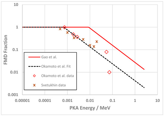
Figure 6.
FMD fraction for Ni as a function of cascade energies for the different PKA values data form [30,31,34].
1.2.1. FMD Production without Consideration of the 59Ni Effect
Given the PKA spectrum as a function of PKA energy, the FMD fraction is calculated using Equation (2). The SPECTER code [22] has an option to generate the PKA spectrum for each individual element but the output does not contain PKAs arising from n,γ recoil reactions. To calculate the FMD fraction, that portion of the DPA arising from n,γ recoils is calculated using the damage energy cross-section, which is also generated by SPECTER, and subtracted from the total DPA. The remaining DPA is attributed to the SPECTER PKA spectrum output and an FMD fraction for the PKA spectrum, FMD(PKA), is derived using Equation (2). The FMD fraction attributed to the total DPA is then,
The recoil energy is small for the n,γ recoil reactions (395 eV for Fe and 491 eV for Ni) and only a few atomic displacements are produced. In these cases, the FMD production efficiency, , is =1 [17]. The PKA and FMD spectra for Ni in a CANDU reactors are shown in Figure 7.
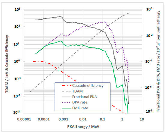
Figure 7.
PKA spectrum, DPA and FMD for Ni in the CANDU reactor core as a function of cascade energies for the different PKA values.
1.2.2. FMD Production with Consideration of the 59Ni Effect
For Ni-alloys in a high thermal neutron environment the mode of damage production can have a large impact on the calculated damage efficiency, which will be considerably lower than that calculated from neutrons when there is a large fraction of damage coming from high energy (n,p) and (n,α) reactions. When considering atomic displacements and the associated FMD production in the context of the production of 59Ni, approximately half of the total atomic displacements can come from the 59Ni (n, α) reaction once sufficient 59Ni has been produced in a reactor with a high thermal neutron flux (such as a power reactor). The FMD fraction is dictated by the recoil energy for the (n, α) reaction, which is 340 keV for the reaction with thermal neutrons, yielding an FMD fraction of 0.01 using the formula of Kwon and Motta [33] and significantly less (5 × 10⁻⁵) using the formula derived from the data of Okamoto and Rehn [31]. Thus, although the recoil energy increases and the DPA is higher with increasing PKA energy, the FMD fraction decreases.
For the reactor spectrum in EBR2, shown in Figure 3, and for 316 SS, the added contribution from 59Ni to the FMDs is <0.01% of the total up to 100 DPA and is therefore negligible. For a high thermal neutron flux such as exists in the Atucha or CANDU reactors, the FMD production efficiency for naturally occurring isotopes at low doses can be very high as the displacements arising from reactions with low energy neutrons is high relative to that from high energy (fast) neutrons. The FMD production efficiency is low for reactions giving rise to high energy recoils, which includes the high energy (n,p) and (n,α) reactions of 59Ni with thermal neutrons. For the CANDU spectrum shown in Figure 3, the contribution to DPA from 59Ni varies with dose and can be as high as 50–60% of the total DPA accumulated after 5 years of operation in a Ni-alloy with a high percentage of Ni such as Inconel X-750. In a CANDU reactor, for a dose of 100 DPA, 55 DPA comes from reactions involving 59Ni. As most of that damage arises from particle emission followed by high energy recoils, the FMD production efficiency is lower than conventional damage and thus the total FMD fraction is reduced as the contribution from 59Ni increases.
The DPA calculated from all the 59Ni reactions [20,21] are separate from the SPECTER output for the naturally occurring isotopes and thus the FMD fraction can be easily factored in to the total DPA, which includes the 59Ni contribution. The emission recoils for 59Ni have been defined [21] and can be factored into the FMD calculation by weighting the displacements that are attributed to 59Ni only by the energy of the recoil for each reaction.
According to Greenwood and Garner the displacements per event from: the 4.76 MeV alpha particle emission, the 1.82 MeV proton emission and the γ-photons, are 1762, 222 and 5, respectively, [20,21]. Atomic displacement calculations resulting from protons and alpha particles obtained from the SRIM code [35] indicate that those ions should produce 26 and 180 displacements respectively. The SRIM code does not consider ionisation losses within the cascade and these values are thus over-estimated [36]. However, taking these values as upper-bounds for the damage produced by the emitted ions directly, one can still make a lower-bound estimate of the displacements from the alpha and proton recoils. For Ni, the recoils induced by thermal neutron absorption and photon emission are low energy (491 eV) and the FMD fraction is =1, see Figure 6. The atomic displacements per recoil and the FMD fractions for each reaction (assuming a single recoil energy [21]) are shown in Table 1, which also shows the values for FMD attributed to Okamoto et al. [31] and Kwon and Motta [33].

Table 1.
FMD fractions for 59Ni reactions using different formulae. Note that the total number of displacements shown below includes the damage from the recoil only.
Rather than attempting to estimate the FMD production efficiency from the ion damage, which would require computing the PKA spectrum at all points along the trajectory of the ions as they lose energy, it will be assumed that the FMD fractions calculated using the recoils only are sufficient to capture the main effect of 59Ni on the FMD fraction. An estimate of the total FMD fraction can therefore be obtained by combining the relative contributions from 59Ni only (shown in Table 1) with those that do not include 59Ni. The FMD contributions are combined by weighting the contributions to the FMD production by the relative DPA arising from 59Ni alone together with the DPA without including 59Ni effects at a given dose. For that purpose, we have arbitrarily chosen to show the FMD fractions when the total dose is 100 DPA, see Table 2.
Table 2.
Combined FMD fractions for different alloys in various reactors using Equation (2) and reactor specific PKA spectra considering the relative contributions from the displacements arising from 59Ni effects at a dose of 100 DPA.
The effective weighted average FMD fractions can then be applied to the total DPA determined for each alloy using the SPECTER DPA output [19,20,21,22] and used in rate theory computations to predict the cavity evolution (swelling) and grain boundary coverage by cavities.
2. Results
The mechanical properties and swelling of stainless steels and Ni-alloys is assessed using rate theory. Of particular interest is the He embrittlement of Ni-alloys irradiated at low temperatures (<350 °C) in the CANDU heavy water reactor for which there are data on mechanical properties as well as data on microstructure evolution from the analysis of ex-service Inconel X-750 components. To calculate the perforation of grain boundaries caused by the accumulation of He-stabilised cavities we must first compute the swelling.
2.1. Swelling
The swelling model for voids has been described in [17] and validated using swelling data for 316 stainless steel in the EBR-2 reactor. The model parameters used here are the same and are listed in [17]. Swelling for bubbles at low temperature has been deduced from density measurements. When combined with measurements and calculations of He concentrations, bubble swelling has been found to be approximately equal to the concentration of He, i.e., He/V = 1 [37].
The void swelling as a function of temperature is calculated assuming that the cavity number density is established early in the development of the microstructure following the trend shown by Bhattacharya and Zinkle [1] for void swelling. The swelling is also sensitive to the dislocation density. Dislocations serve as biased interstitial sinks allowing for a net vacancy flux to cavities. The dislocation structure is a combination of network dislocations created by cold-working and dislocations loops that form during irradiation. The dislocation loop density is sensitive to temperature and that, together with the recovery of the cold-worked dislocation structure, can result in lower dislocation densities during irradiation compared with the original as-fabricated microstructure. Dislocation densities from both sources are reflected in the yield strength. For this reason, an empirical model based on measured yield strengths was adopted in an earlier study [17]. The same empirical model for dislocation density is adopted for this work. We have assumed that the effect of any precipitate formation is negligible. Whereas precipitates may act as nucleation sites for vacancy clusters, it is assumed that any precipitate formation is captured in the yield strength data and that precipitates are sources of lattice strain that act the same as dislocation loops.
Previously it was shown that, for data from EBR2, the best fit of the rate theory model for void swelling could be achieved by using a cavity surface energy (s) = 1 J.m−2 and a recombination parameter (r) = 500. The recombination rate parameter in the model is given as () where is the lattice parameter, which for a face-centred-cubic (FCC) lattice = 0.36 nm, and r is a geometric factor that corresponds with the number of interstitial sites around a vacancy where spontaneous recombination can occur. The value of r recommended can vary between 50 and 500 [38]. The surface energy (s) is also variable; different researchers using values ranging between 1 and 2 [16,17].
Although the swelling algorithm [17] was developed to apply to data from EBR2, which has a low He production rate, the principles are the same for all reactor conditions and the limitations come mainly from the empirical models derived for dislocation evolution and the pressure in the cavities, with varying amounts of helium and vacancies, as the microstructure evolves with increasing dose. Applying the model for EBR2, PWR, CANDU and Atucha spectra corresponding to central locations of each reactor core, one can see differences in the temperature dependence of the swelling for different alloys as illustrated in Figure 8. Note that the swelling computation is for hypothetical temperatures for the power reactors whose operating temperatures fall in a narrow range of temperatures between 200 °C and 350 °C. Also included in Figure 8 is a hypothetical case for a high damage rate like in EBR2 but with a He production rate that is equivalent to a high flux reactor such as HFIR, labelled HFIReq. We have not used a spectrum from HFIR, partly because the spectra in HFIR vary widely depending on location in and around the core but also to illustrate the effect of He on swelling by using the EBR2 (row 2) damage rate with a He/DPA equivalent to a HWR. The swelling rate at any point in time is dependent on the dislocation structure, damage rate, temperature, and He generation rate. The He controls the stability of cavities so that when the He generation rate is high, as it is for Inconel X-750 in the CANDU reactor, the swelling rate does not decrease at high temperatures (>550 °C) as it does for EBR2 and PWRs, for which the He generation rate is lower. In the latter cases one sees that increasing the atomic displacement rate (such as in EBR2) shifts the peak swelling to higher temperatures. The effect of He, which helps stabilise cavities at high temperatures when they would otherwise shrink, is apparent from the swelling curves for the CANDU and Atucha spectra that have very high rates of He production per unit DPA. Typical He generation rates as a function of DPA (i.e., He/DPA) at 100 DPA corresponding with the five cases shown in Figure 8 are listed in Table 3. Note that for EBR2, the spectrum corresponds with the centre line of row 2. Further out from the core the He/DPA increases, e.g., from 0.16 for row 2 to 0.28 for row 8.
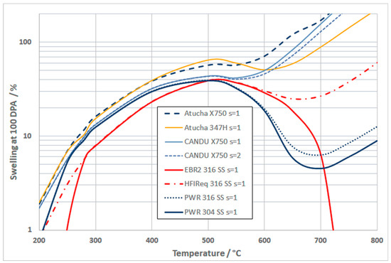
Figure 8.
Swelling at 100 DPA for different alloys in different reactor cores as afunction of temperature. The surface energy, s, shown in the legend refers to either 1 or 2 J.m−2 (see text).
Table 3.
He/DPA for different alloys irradiated in various reactors.
EBR2 (row 2) and PWR reactor spectra, for which the He/DPA is low (~0.2 to 10 appm He/DPA), have different high temperature behaviour compared with Atucha and CANDU reactor spectra for which the He/DPA is considerably higher (up to ~100 appm [He]/DPA for 347H SS and up to ~300 [He]/DPA for Inconel X-750). The higher He/DPA ratio results in more swelling at higher temperatures for the Atucha and CANDU spectra where otherwise the vacancy emission would dominate when the ratio of He atoms to vacancies in the cavities (He/V) is low. The algorithm for void swelling has been described in detail in [17].
At low temperatures (<300 °C) and high He generation rates the cavity stability is governed by the He/V ratio in the cavities. Whereas the He/V ratio in the cavities is evolving, and dependent on the individual conditions for each curve shown in Figure 8, the stability of cavities at high temperatures (>550 °C) for the HWR spectra is also dependent on the amount of He that is being generated for those reactor spectra. At low temperatures the swelling is dependent on the He content so that when the He content is low (as it is in EBR2) the swelling cannot be sustained by a net vacancy flux, which is given by the product of the vacancy concentration and diffusion coefficient. The He itself stabilises vacancies and vacancy clusters and the swelling is determined by thermal effects. Under these conditions the cavities are called bubbles. There is thus a transition from bubble swelling at temperatures <300 °C to void swelling at temperatures >400 °C.
The dependence of cavity stability on temperature and He content can be illustrated using rate theory. Using the model developed previously [17] for an austenitic alloy the effect of temperature on the net flux of vacancies to cavities having different diameters and a constant number density (1023 m−3) is shown in Figure 9 for He/V ratios of 0.01 and 1. In this example the damage rate is about 2 dpa/year corresponding approximately to that in a PWR or HWR. These plots show the temperatures at which there is a transition to bias-driven growth, i.e., when the cavity growth rate increases with increasing temperature. The temperature at which there is a transition to bias-driven growth is dependent on the cavity size, decreasing as the cavity size increases. The transition temperature is a complex function of the He/V ratio, the cavity diameter and the dislocation microstructure at that temperature. For low He/V ratio (=0.01), cavities that are >5nm in diameter are unstable at temperatures greater than about 350 °C, i.e., vacancy emission dominates the cavity growth at such low values of He/V ratio. For a high He/V ratio (e.g., =1) the transition to bias-driven growth occurs at lower temperatures as the cavity diameter is increased.
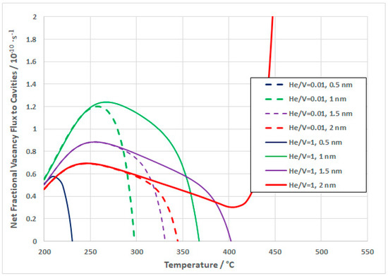
Figure 9.
Rate theory output showing the vacancy flux to cavities of varying diameters as a function of temperature for Inconel X750 in a PWR or HWR (~2 DPA/year) for different cavity diameters and He/V ratios of 0.01 and 1.
The effect of cavity diameter at a constant number density (1023 m−3) on the net flux of vacancies to cavities at different temperatures is shown in Figure 10 for He/V ratios of 0.01 and 1. At low temperatures small cavities (<2 nm diameter) have high vacancy absorption rates. The rate of vacancy absorption decreases substantially as the cavities/bubbles grow. At 350 °C and above, the cavities evolve into sink-dominated behaviour where the rate of absorption of vacancies increases with increasing cavity diameter, provided that the He/V ratio is large enough. At low values of He/V, e.g., 0.01, the cavities (bubbles) are stable at low temperatures and are unstable for temperatures >350 °C with a limited range of stability at 350 °C.
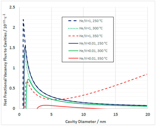
Figure 10.
Net vacancy flux to cavity sinks as a function of cavity diameter for Inconel X-750 irradiated in a generic reactor.
Coincidentally, the void swelling model only applies to the conditions where the void number density can be defined empirically, i.e., for temperatures >350 °C [1,17]. It is reasonable to assume therefore that the cavities are bubbles at temperatures <350 °C, provided the He/V ratio is large enough, and are voids for temperatures >350 °C. Naturally, the microstructure is evolving continuously as the swelling progresses and both the cavity diameters, and the He/V ratio change as the microstructure evolves.
2.2. Cavity Accumulation on Grain Boundaries
2.2.1. Theory
There are numerous problems involved in obtaining measurements for the accumulation of cavities on grain boundaries. Rate theory modelling has therefore been applied to predict the grain boundary coverage as a function of operating conditions. The model should not be considered definitive, rather an indication of how the grain boundary microstructure evolves with certain assumptions. The most important aspect of the modelling is not necessarily in calculating the absolute area coverage, rather in describing the trend in area coverage with dose and temperature.
The net vacancy and He flux grain to boundaries is dependent on the grain size and the sink strengths of dislocations and cavities within the grain interior. In the bubble regime at temperatures <350 °C the cavity size and number densities are dictated by the availability of He. Density measurements have shown that the swelling is proportional to the He content such that the average cavity He/V ratio for bubbles within the grains is about 1 [18,37]. With this assumption the bubble number density can be deduced from the measurement of the mean cavity diameter, which decreases with increasing temperature, given a calculated value for the [He] concentration. From the bubble diameter and density deduced from the [He] content, given He/V = 1, the sinks strengths are calculated and serve as input to rate theory calculations for the net vacancy and He flux to grain boundaries. Likewise, the void sink strength in the swelling regime can be calculated given the calculated swelling and number density data described in the previous section.
In both the bubble and void regimes, the sink strength dependence on temperature will be dependent on the number density and the cavity diameters. In both cases the cavity sink strength in the grain interior decreases with increasing temperature even though the cavity diameters increase,
where D is the cavity diameter and ρ is the cavity number density.
For voids the sink strength is dependent on the bias-driven growth. For a given cavity diameter (D) the swelling is proportional to D3, while the sink strength is proportional to D. So, although the voids may have a lower number density (ρ) at higher temperatures, the swelling can still increase while the sink strength decreases. The bubble number densities are relatively insensitive to temperatures <350 °C, and the diameters are mostly determined by the amount of He in the system. The sink strengths in the bubble regime have a different temperature trend compared with voids [1].
When the internal sink strength is high, i.e., when the swelling is large, fewer point defects (vacancies and He atoms) migrate to grain boundaries and one can expect a decreasing rate of grain boundary coverage as the swelling (internal cavity sink strength) increases. Just as the swelling is a non-linear function of the cavity diameter, the grain boundary area coverage is also non-linearly dependent on the mean diameter of cavities on the boundary. In the latter case, for a given number of vacancies, the area coverage decreases as the cavity diameter increases. The grain boundary area coverage as a function of temperature is thus a complex function of the grain interior sink strength and the average cavity diameters on the boundary. It is assumed that the diameters of the cavities on the grain boundaries are double that of the grain interior to be consistent with observations [18]. This then forms the basis for modelling grain boundary coverage. The modelling is separated into two parts: (i) a low temperature bubble growth regime at temperatures <350 °C; and (ii) a high temperature void growth regime for temperatures >350 °C. The transition from bubble to void regimes will not be abrupt but will occur gradually over the temperature range between 300 °C and 400 °C. However, to simplify the analysis we will assume that there is an abrupt transition at 350 °C.
The diffusion-rate-limited kinetics of point defect annihilation at different sinks has been determined by many different researchers, but each give the same essential results that are derived by first considering the rate of diffusion of the point defects to an individual sink and then scaling up to the total number of sinks per unit volume (the sink density). Sinks are not uniformly distributed and there will be spatial variations in their distribution, but the rate theory calculations presented here are tractable because they are based on averages; an average sink density for an average point defect concentration in the medium mid-way between the sinks; this is the so-called mean-field approach. Mean-field refers to averages and steady-state or pseudo-steady-state behaviour. The rate theory calculation gives a rate for a given set of conditions and can be adjusted as the microstructure evolves at each time step. The changes in the evolving microstructure can either be calculated using rate theory or as an input derived from experimental data. For the purposes of this report, there are only three types of sinks to consider: (i) dislocations, (ii) cavities, and (iii) grain boundaries. The derivation of the sink strengths will be described for each.
Dislocations
By solving diffusion equations with cylindrical geometry, Heald and Speight [39] showed that the rate constant for point defect interactions with dislocations is
where is the dislocation density of a given type of dislocation and is the average distance a point defect travels before encountering a dislocation, and
where R is the mean distance between dislocations and is determined from the elastic strain field interactions between the dislocation and respective point defects. One can think of as the radius of an effective trapping cylinder [39].
Cavities
By solving diffusion equations with spherical geometry, Heald and Speight [39] also calculated the sink strengths for cavities. Cavities are considered “neutral” sinks because, unless highly pressurized, the strain field is not large compared to the cores of dislocations. Accordingly, the same reaction rate expression is applicable for both interstitials and vacancies.
where is the cavity radius and is the cavity number density (number per cubic metre) and is the average distance a point defect travels before encountering a cavity. Recent work shows that when cavities are small and under-pressurised there is an interaction with interstitial point defects that can delay cavity evolution and thus increase the incubation time for the onset of swelling [40]. This interstitial bias is inversely related to cavity diameter and pressure and increases at lower temperatures. Such an effect could account for the longer incubation times that have been observed for 316 SS irradiated in EBR2 [17]. Whereas such a consideration may be useful in void nucleation models, we use empirical data for cavity nucleation as a function of temperature and only consider cavity growth after the nucleation stage. The expression (7) thus stands. although there may be a small effect of interstitial bias that can be subsumed into a net interstitial bias for dislocations (the bias differential between dislocations and cavities). It should be noted also that pressurisation of the cavities alleviates the bias thus reducing the probability for interstitial absorption by bubbles [40].
When cavities are pressurized, it is assumed that the main influence of the pressurization is in the absorption and emission of vacancies from the cavity surface. Apart from the free energy of the vacancy itself, the free energy change of the cavity caused by the absorption of one vacancy is given by −()Ω, where p is the pressure in the cavity, γ is the surface energy of the cavity, r is the cavity radius and Ω is the atomic volume [7,8,9,10,11,17].
Grain Boundaries
Grain boundaries are a special case. Although the high densities of cavities and dislocations within the matrix can be assigned average sink strengths and the partitioning of point defects between those sinks can be calculated assuming no other interactions, the flux of point defects to the grain boundaries surrounding the sinks within the grain is determined by the mean steady-state concentration in the interior and the concentration gradient at the boundary. As the steady-state point defect concentration in the matrix is a function of the total sink density within the grain, the grain boundary sink strength is not only dependent on the grain boundary density (grain size) but also on the density of other sinks within the grain interior.
The sink strengths of grain boundaries have been calculated assuming spherical geometry (treating the grain as a sphere of diameter d), while considering the internal sinks within the grains [41]. The diffusion of point defects to the grain boundary is determined from the steady-state point defect concentration within the grain interior and the concentration gradient at the boundary, assuming that the boundary itself is a perfect sink. As for the cavities, the same reaction rate expression is applicable for both interstitials and vacancies. If the average diffusion length averaged over all sinks is λ, then the sink strength for the grain boundaries are given by,
when the diffusion length for the interior is very much smaller than the grain boundary dimensions. Alternatively,
when the diffusion length for the interior is very much larger than the grain boundary dimensions.
Harkness and Li [42] showed that the sink strength for diffusion of point defects to the grain boundary per unit volume is composed of two parts: (i) the concentration gradient at the boundary (c − co)/λ, where c is the mean-field steady-state point defect concentration in the grain interior, co is the concentration at the boundary; and (ii) the grain boundary area per unit volume, ≈ 6/d. Considering the boundary to be a perfect sink, co is assumed to be zero. It is further assumed that λ is the mean diffusion length for point defect species within the grain interior, i.e.,. The result is the same as that derived by Heald and Harbottle [41] for high sink densities in the grain interior. When the cavity density is high λ is about the same as (the average diffusion length for the grain interior cavity microstructure). When a denuded zone is present it is assumed that λ = L + dx, where dx is the denuded zone width (Figure 11), although for simplicity the calculations in this paper do not include the effect of a denuded zone.
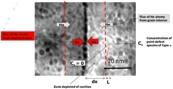
Figure 11.
Diagram illustrating source of He flow to grain boundaries. Half of the He generated in the denuded zone is assumed to migrate to the grain boundary and half migrates into the grain interior. The He flux from the interior is equivalent to the He flux to the boundary that would exist in the absence of a denuded zone; this flux to the boundary is reduced by the presence of the denuded zone.
The net vacancy flux to cavities on the grain boundary () is the product of the net vacancy flux to the boundary () and a vacancy reaction term that is a function of the pressure, and thus He content within the cavities. The flux of vacancy point defects to cavities is given by,
where P is the pressure, r is the cavity radius, is the surface energy, Ω is the atomic volume and σ is the area fractional cross-section. Increasing the pressure in a pressurised cavity effectively increases vacancy and decreases interstitial absorption. The reaction term gives a probability related to the work done when a cavity absorbs an interstitial or a vacancy point defect. There is the added complication of a possible intrinsic interstitial bias for cavities [40]. However, such a bias is only effective at the nucleation stage, is reduced for pressurized cavities and is not deemed significant for these calculations (see Section 2.2.1). There is another possible complication regarding applied stress. Luo et al. [43] have shown that the interstitial bias for cavities decreases for cavities on grain boundaries perpendicular to an applied tensile stress for stress levels up to 120 MPa. Applied stresses are not considered in this treatment, but if there was an effect of stress on either vacancy or self-interstitial point defect diffusion, the accumulation of cavities on boundaries perpendicular to a tensile stress is contrary to the principle of Herring-Nabarro creep [44,45], which requires interstitials to migrate to boundaries perpendicular to the tensile stress, not the other way around. This inconsistency concerning stress effects has been addressed in a previous review [28] noting that, rather than being contrary to Herring-Nabarro creep the effect of stress in promoting interstitial He diffusion to grain boundaries perpendicular to the tensile stress would be consistent with Herring-Nabarro and is a more logical explanation for the observations that cavities are more prevalent on grain boundaries perpendicular to a tensile stress. A schematic diagram describing the interaction of point defects with cavities on grain boundaries is shown in Figure 12.
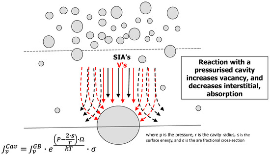
Figure 12.
Schematic diagram illustrating source of vacancy and interstitial point defect flux to grain boundaries. There is a higher vacancy, relative to interstitial, flux from the grain interior. The flux to cavities is a function of the point defect flux to the boundary and an interaction term. p is the pressure, r is the cavity radius, is the surface energy, and σ is the area fractional cross-section.
The net flux of point defects to boundaries (He atoms and vacancies) is dependent on the grain interior sink strength, as shown in Figure 11 and Figure 12. At low temperatures the elevated steady state vacancy concentration that exists because of the low vacancy mobility is important because vacancies are strong traps for He atoms [3]. The size of the cavities on the boundary is also important because smaller cavities have a higher area coverage for a given cavity volume. The net effect is complicated and is best observed by simply running a model including all the parameters discussed here.
2.2.2. Model Results
Measurements from cavity number densities and mean diameters for Inconel X750 in the CANDU reactor show considerable variability but the sink strengths generally show the same trend, decreasing sink strength with increasing temperature, Figure 13 [18,37]. Also shown in Figure 13 are the sink strengths obtained from a void swelling model [17] for EBR2, a PWR and a CANDU reactor to show how the sink strength in the void regime has a different trend with temperature.
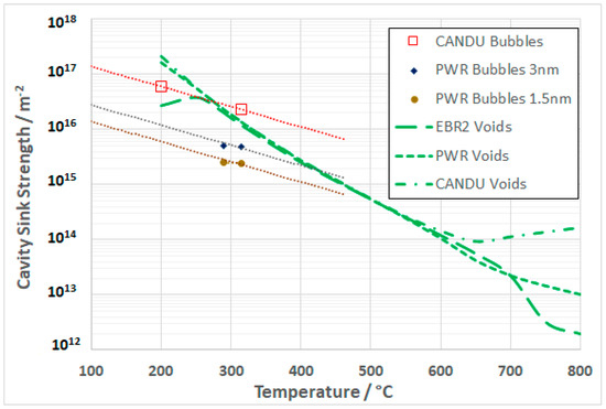
Figure 13.
Sink strengths (= , where is the cavity number density and D is the diameter, of Inconel X-750 in CANDU reactor and 316 SS in a PWR extrapolated to 100 DPA as a function of temperature. Also shown are the sinks strengths for voids calculated for various reactors at 100 DPA.
The modelling in the bubble regime is restricted to the grain boundary cavity coverage of Inconel X-750 in a CANDU reactor and 316 stainless steel in a PWR reactor for which bubble measurements exist as a function of temperature. In the PWR case only approximate data concerning bubble diameters and number densities at two temperatures (315 °C and 290 °C) are available [46]. Unfortunately, although the number densities were given, the diameters were not measured accurately and a nominal value (<3 nm) was quoted for two dose levels. In the CANDU case many measurements have been obtained for cavity diameters and densities [18,37] at nominal estimated temperatures (315 °C and 200 °C) and a range of doses. Because of the large range of variability of the grain interior sink density and bubble diameter measurements in the bubble regime, the upper limits of the mean cavity size at 80 DPA have been used to obtain cavity number densities and thus sink strengths as a function of temperature. Assuming the trapping of He by single vacancies is a dynamic process, i.e., any accumulation contributes to the observed bubble structure, the error from ignoring the He that will be trapped in single vacancies at EOL, when the swelling from immersion density is measured, is estimated at about 10−4 and 10−6 for material irradiated at 200 °C and 300 °C respectively. Ignoring this contribution to the swelling will result in an over-estimate of the cavity diameter by a small fraction. The cavity number density was therefore calculated for a given mean cavity size to be consistent with the measured swelling without taking into account the contribution from the single vacancy traps [18,37]. The values used for the bubble microstructures are shown in Table 4.
Table 4.
Bubble microstructure data for CANDU and PWR.
In the model the CANDU data are extrapolated to 100 DPA by assuming the bubble number density is constant and the bubble volume evolves at a rate proportional to DPA. The PWR data are extrapolated to 100 DPA by assuming the bubble number density is still evolving (lower He generation rate) and the bubble volume evolves at a rate proportional to DPA. As the data were only provided as “less than”, two mean diameters were assumed, 3 nm and 1.5 nm. In this way, although the sink strengths are guesses, the effect of changing the sink strength can be seen in the model. The model uses grain interior sink strengths at a give dose (say 100 DPA) as a target and the grain interior sink strength is assumed to vary linearly with dose until the target value is achieved. The target sinks strengths for bubbles in CANDU and PWR conditions extrapolated to 100 DPA are shown in Figure 13. For the two PWR cases the sink strengths are referred to as upper and lower in the model outputs.
At higher temperatures (in the void swelling regime) the grain interior void sink strengths are calculated from a swelling model previously published [17]. The cavity diameters at 100 DPA are calculated for the respective operating conditions and combined with the number densities at each temperature [1,17]. The corresponding cavity sink strengths as a function of temperature used as inputs to the grain boundary coverage model are shown in Figure 13. The dislocation sink strengths as a function of temperature have been calculated using an empirical model developed previously [17] and are applied equally for the bubble and void conditions.
In addition to the role of cavities and dislocations in competing for point defects, He-trapping at vacancies, which have a higher steady-state concentration at lower temperatures, is also included in the model. The effect of single vacancy traps on the net vacancy flux to grain boundaries is negligible at temperatures >300 °C because the calculated vacancy concentrations translate into sink strengths are of the order of 1012 m−2 and thus have little effect compared to trapping by the large vacancy clusters, i.e., the cavities. At lower temperatures however, in the bubble regime, the role of single vacancies is an important element in the model with the single vacancy sink strengths rising to levels of the order of 1015 m−2 at 200 °C. The single vacancy sink strengths are about 3 orders of magnitude higher at 200 °C compared with 300 °C and are thus important traps for He atoms at the lower temperature.
While the values used for bubble sink strengths are not ideal, especially in the case of the PWR data, they are to be considered best estimates given both the paucity and large scatter in the available data. For the purposes of demonstrating the principles of the model the data shown in Figure 13 are thus the best that can be assumed at this time. In principle the lower sink strength for PWR compared with CANDU conditions is directionally correct given the much higher (30 fold) He production rate in the CANDU conditions, which would likely result in a higher bubble nucleation density.
With the internal microstructure defined at a certain target dose (100 DPA), as plotted in Figure 13, one can calculate the effect of the evolution of the internal sink structure on the flow of point defects and He atoms to the grain boundaries and thus calculate the degree to which the boundaries become perforated with cavities (bubbles or voids) with dose. The algorithm for the evolution of the cavities on the boundary is shown in Figure 14.
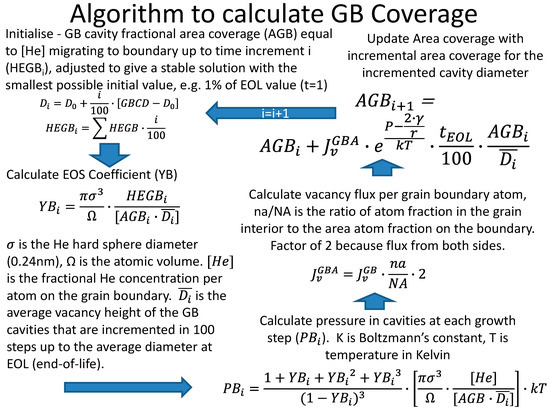
Figure 14.
Algorithm describing the grain boundary cavity evolution subject to a vacancy and He flux to the boundary up to a target end-of-life (EOL) time.
Grain Boundary Coverage for a CANDU Reactor Neutron Spectrum
For Inconel X-750, the grain boundary coverage is calculated assuming that the grain interior microstructure can be described by either: (a) bubble evolution or (b) void evolution models.
Applying the algorithm (Figure 14) to the case for cavities in Inconel X-750 irradiated in a CANDU reactor neutron flux, the evolution of the grain boundary coverage as a function of temperature are shown in Figure 15a, for the case of bubble sink strengths, and Figure 15b, for the case of the void sink strengths. Note that the expected operating temperatures of components in the CANDU reactor do not exceed 350 °C and inclusion of hypothetical calculations for higher temperatures is included to encompass the range of temperatures of interest for this study. The surface energy used was that found to give the best agreement with swelling, [17], i.e., 1 J.m−2. The grain boundary area coverage at 100 DPA for surface energies of 1 and 2 J.m−2 is illustrated in Figure 16. Increasing the surface energy lowers the grain boundary area coverage when using the bubble swelling sink strengths compared with the void swelling sink strengths shown in Figure 13. Figure 16 also illustrates that the area coverage increases with increasing temperature in the bubble regime but is relatively insensitive to temperature in the void regime up to about 550 °C. At temperatures higher than 550 °C the grain boundary coverage decreases, corresponding with the increase in the swelling that is predicted for Inconel X-750 in CANDU reactor conditions, Figure 8.
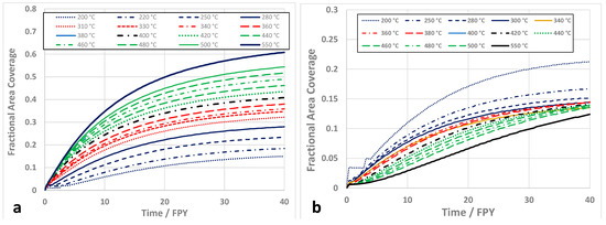
Figure 15.
Hypothetical grain boundary cavity coverage as a function of dose (DPA) for Inconel X-750 material irradiated in the neutron flux of a CANDU reactor assuming: (a) a bubble evolution model; (b) a void evolution model. The surface energy (s) was assumed to be 1 J.m−2 and the recombination parameter (r) was assumed to be 380.
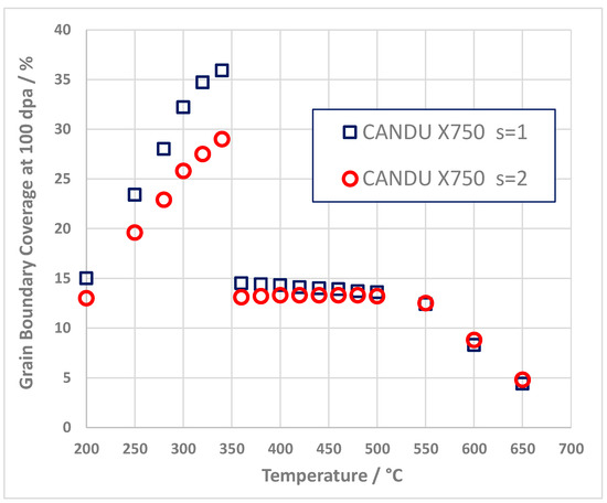
Figure 16.
Calculated grain boundary cavity coverage as a function of temperature after 30 years of operation for Inconel X-750 material (100 dpa) irradiated in a neutron spectrum typical of a CANDU reactor core for two values of cavity surface energy (s = 1 or 2 J.m−2) and assuming an arbitrary shift from bubble to void-swelling regimes at temperatures >350 °C.
Grain Boundary Coverage for a PWR Neutron Spectrum
The grain interior sink strengths at 100 DPA resulting from the evolution of either bubbles or voids for 316 SS in a PWR are shown in Figure 13. The sink strengths for the PWR case are lower by a factor of 5 or 10 compared to the CANDU case and this can be attributed to the lower number density, which is in turn correlated with a lower He concentration. Note that in a previous publication the grain boundary coverage for a PWR was calculated using an assumed sink strength that was considerably lower than the more reasonable values used here and therefore gave higher coverage results. The current PWR data, although crudely estimated, are better estimates for the PWR because they are assumed to follow the same temperature dependence as the CANDU data. The predicted grain boundary area coverage for 316 SS in a PWR as a function of temperature at 100 DPA is shown in Figure 17. Data calculated according to the two upper and lower interior sink strengths estimates are labelled in each case. In doing this one can see the effect of changing the grain interior sink strengths, a higher grain interior sink strength leading to lower grain boundary coverage and vice versa. For comparison, the CANDU Inconel X-750 data are also shown, illustrating the effect of the higher He generation rate. Note that at high temperatures, >550 °C there is an increase in the grain boundary coverage as a function of temperature for the PWR case and then a decrease for temperatures >650 °C mirroring the swelling behaviour (Figure 8). Likewise, there is a decrease in grain boundary area coverage with increasing temperature over the same temperature range for the CANDU case that also mirrors the swelling behaviour, shown in Figure 8. The prediction is even more extreme for grain boundary coverage for 316 SS in EBR2 also shown in Figure 17. In that case the coverage is small at temperatures corresponding to the peak swelling regime but increases rapidly at temperatures >700 °C where swelling is very low. For the HFIR equivalent spectrum the coverage is mostly flat over a large temperature range, again mirroring the swelling behaviour.
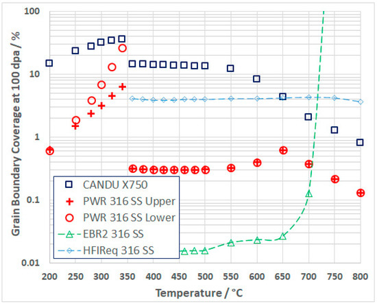
Figure 17.
Calculated grain boundary cavity coverage as a function of temperature after about 100 dpa for 316 SS subject to a PWR, EBR2 and HFIR equivalent spectra and Inconel X-750 subject to a PWR equivalent spectrum (both core average fluxes). The 316 SS in the PWR use sink strengths that are upper and lower bound estimates from published data (see text).
The differences for each reactor spectrum and material can be attributed to the effect of He in stabilizing cavities and thus enhancing swelling at high temperatures when void swelling, in the absence of He, would normally be small [17]. There is still a small amount of He present in the EBR2 case that is sufficient to stabilize cavities on grain boundaries when there is minimal swelling.
3. Discussion
3.1. Swelling of Austenitic Alloys
The dimensional stability of austenitic stainless steels is largely dependent on cavity (void) swelling, which is also dependent to some extent on having He present to stabilise cavities against collapse to vacancy dislocation loops. Using a rate theory model that was previously validated using good quality swelling data for 316 SS irradiated in EBR2 [17], we have expanded the study to include other austenitic alloys used in various nuclear reactors by applying the model and computing the swelling at 100 DPA as a function of temperature using appropriate spectra relevant to particular reactors. Because He is generated in many reactor spectra and is an integral part of any swelling model we have computed the He production for each spectrum and included these values in the model so that the effects of He become apparent. A large temperature range (200–800 °C) has been assessed but it should be noted that for power reactors the range of temperatures studied does not reflect the temperature range likely to be experienced in the cores during normal reactor operation (200–350 °C).
The nucleation of cavities has not been modelled. Rather, experimental data compiled by Bhattacharya and Zinkle [1] have been used for cavity number densities as input assuming the nucleation is established early on in the irradiation and the number densities remain constant with increasing dose thereafter. The model results show that the irradiation-induced swelling of austenitic alloys typically increases with increasing temperature for temperatures >200 °C. For cases where the He production rate is low (<10 He appm/DPA), as in PWRs and fast reactors like EBR2, there is a peak in the measured swelling rate per unit dose at temperatures of about 500 °C. When the He production rate is high, as it is in HWRs and high flux reactors such as HFIR, the swelling follows a similar trend up to about 500 °C, but rather than decreasing at higher temperatures there is an uptick in swelling that can be attributed to the stabilising effect of He. Most swelling data come from irradiations in fast reactors such as EBR2 or high flux reactors such as HFIR. The model reproduces the swelling from EBR2 well except for the incubation period before the onset of swelling that increases as the temperature falls below 500 °C [17,47]. It was hypothesised that the longer incubation at lower temperatures may have been related to trapping of He at dislocations [17] but recent theoretical work has indicated that it may also be related to the interstitial bias for small vacancy clusters that increases with decreasing temperature [40] therefore inhibiting nucleation as the temperature falls below 500 °C [17,47]. The uptick in swelling for high He/DPA ratios at temperatures >550 °C shown by the model is consistent with limited swelling data reported for HFIR [48,49].
Applied to the evolution of cavities on grain boundaries the model has shown that increased swelling is coincidental with lower grain boundary coverage by He-stabilised cavities. It is noteworthy that the ductilities of austenitic alloys irradiated in fast and high flux reactors increases at temperatures >500 °C [50]. This may be attributed in part to a lower defect density so any effect of He-embrittlement is confounded by other microstructural features, even swelling-induced embrittlement [47], which is not related to grain boundary perforation by cavities. As there are many different aspects of the microstructure that are changing with irradiation temperature it is difficult to single out any one effect. However, in [50] the authors do state that “Ductility appears to be higher for alloys irradiated in fast reactors where little helium is produced, but even for fast reactor irradiation, ductility begins to drop above 700 °C. This behavior, which is enhanced by higher helium concentrations, is believed to be a result of helium embrittlement.”
3.2. Embrittlement of Austenitic Alloys
Austenitic alloys that include some stainless steels and many Ni alloys, have better ductility and strength, during and after irradiation, compared to other core materials such as Zr-alloys [16], except when there are large numbers of cavities created during irradiation. These alloys have an FCC structure because of the presence of Ni, which is particularly prone to n,α reactions that create He in a power reactor environment. Unlike Zr-alloys, austenitic alloys can suffer from He-embrittlement at high doses and temperatures provided they operate in a neutron spectrum that produces sufficient helium from n,α reactions [50,51,52].
The phenomenon known as He embrittlement can be categorised as low- and high-temperature and is briefly summarised in the Supplementary Material, Sections S1 and S2 respectively [18,26,27,37,46,53,54,55,56,57,58,59,60].
Low temperature He embrittlement is characterized by a transition from ductile to inter-granular fracture after irradiation (Figure S1). The fracture is associated with the segregation of a high density of He-stabilised bubbles on grain boundaries (Figure S2). The embrittlement applies to enhanced inter-granular fracture during post-irradiation SCC testing and is also linked to He-stabilised bubbles segregated at grain boundaries (Figure S3). Often samples will fail in the elastic regime during post-irradiation tensile testing (Figure S4).
Failure in the elastic regime is also observed for high temperature He embrittlement (Figure S5). Although the material shown in Figure S5 is a ferritic alloy, the same characteristics of inter-granular failure, associated with He-stabilised cavity segregation at grain boundaries, are exhibited (Figure S6). Even though the ferritic alloy in question had low swelling, it was still embrittled because of the segregation of He-stabilised cavities at grain boundaries. He stabilizes cavities on boundaries and He embrittlement is therefore not necessarily associated with high swelling. For self-ion irradiation there can be a high density of voids in the matrix and none on boundaries. Figure S7a shows a high density of voids in a ferritic steel irradiated to a very high dose (500 DPA) with no evidence of any segregation on grain boundaries. Figure S7b shows a sample of 316 SS after testing at 50 MPa in tension with simultaneous He-ion irradiation to the point of rupture at 750 °C. There are many He-stabilised cavities on grain boundaries but few in the matrix.
There is another embrittlement mechanism that applies to austenitic alloys at high doses, i.e., swelling embrittlement, that is not necessarily associated with perforated grain boundaries and is briefly summarised in the Supplementary Material, Section S3 [16,61,62]. Swelling-induced low ductility failure has been observed in austenitic alloys and is attributed to the weakening of the material by high densities of cavities. The fracture surfaces exhibit ductile dimpling (Figure S8). Although some involvement with grain boundaries has been noted (Figure S9), the failure is still ductile and is not the same as the more localised inter-granular failure attributed to He-embrittlement.
The intra-granular fracture phenomenon that has been dubbed channel fracture may be a misnomer as there is evidence that the fracture may be associated with cavity segregation at platelet interfaces within austenite grains (Figure S10). The platelets may be large precipitates, incoherent twins, or martensite platelets. In that sense there are instances of trans-granular fracture that may also be linked to He embrittlement as discussed in the Supplementary Material, Section S4 [63,64,65].
There may also be some overlap between He-embrittlement and irradiation induced stress corrosion cracking (IASCC) in cases where the effect of irradiation is not only to harden the material but also to degrade the grain boundaries so they become more susceptible to inter-granular stress corrosion cracking (IGSCC). This possibility is outlined in Supplementary Material, Section S5 [66,67,68,69,70]. High densities of small He-stabilised bubbles have been observed segregated at grain boundaries in austenitic alloys during irradiation at power reactor temperatures (see Figure S3b). It is conceivable that He segregation will enhance the sink strength of the boundaries with respect to vacancy absorption and this will have an effect on the concentration of fast diffusers such as Cr that will be depleted at vacancy sinks (the bubbles) by the inverse-Kirkendall mechanism (Figure S11). Anorther factor, not necessarily linked with He, is the enhancement of self-diffusion by irradiation. Elements such as Cr that are both carbide formers and fast diffusers may show characteristics (such as sensitization) that are normally attributed to high temperature thermal treatments (Figure S12).
Normally grain boundaries are the strongest part of any material, having a structure that is closer to amorphous compared with the softer crystalline lattice that can deform relatively easy by dislocation slip. The presence of grain boundaries that are perforated by He-stabilised cavities reduces the stress that needs to be applied to cause fracture, which is characteristically inter-granular in nature. This He-embrittlement is coincident with a reduction in ductility. Whereas the ultimate failure is inter-granular in nature, fracture may often be preceded by bulk yielding within the matrix. However, there are many examples where failure occurs without any sign of macroscopic plastic deformation prior to failure [16,27,28]. Ultimately, some form of shear that is restricted to the perforated region at the boundary, i.e., between the cavities, is likely to be involved. The notion that decohesion is a viable mechanism is unlikely because, even when there is a reduced contiguous area of two adjoining grains, the stresses needed to simply pull the grains apart are still very high. The reduced ductility characteristic of He-embrittlement is often coincident with reduced engineering stresses at failure that can be below the bulk yield stress. In contrast to other failure mechanisms He embrittlement is characterised by both inter-granular and trans-granular fracture because grain boundaries and incoherent interfaces are perforated by He-stabilised cavities that are sites for easy crack propagation.
The inter-granular fracture of austenitic alloys has been well documented [16,27,28,49,50,51,52,53,64,71,72,73,74]. It is reasonable to suppose that in many cases embrittlement is directly related to the perforation of the grain boundaries, and it is further assumed that the degradation in mechanical strength as a function of dose is a function of the amount of perforation [37]. One of the first concerns of a reactor engineer when seeing evidence of mechanical property degradation is whether the effect is likely to accelerate with time (dose). The main purpose of the grain boundary perforation model presented here is therefore to show that the rate of change in perforation is not likely to be increasing with increasing dose. The results indicate that the predicted degree of perforation (grain boundary coverage) is decreasing with increasing dose. Without a mechanistic explanation of the effect, the trend cannot be predicted with any confidence. The rate theory model presented here provides an explanation for the changes in mechanical properties and forms the basis for the development of mechanical models to predict failure loads outside of the range of current data [37]. The extrapolation applies not only to time/dose but also to dependencies on other factors such as temperature and dose rate.
Predictions of maximum load carrying capacity from the polycrystalline finite element simulations of an Inconel X-750 component irradiated in a CANDU reactor are shown in Figure 18 [37]. The mechanical model includes the development of an empirical relationship between the extent of perforation and the point of failure by traction forces applied to the boundary. It was developed to predict the failure load when a spacer coil is loaded in compression after removal from the reactor. During operation the spacers are only loaded over a short length that is pinched between the fuel channel and the surrounding calandria tube. Whereas there will be some outer-fibre stress on small sections of the spacer coils there is no evidence that this stress has any effect on post-irradiation properties. Those parts that are of most interest (the unpinched sections having the worst degradation) are not subject to any stress during service. The data refer to room temperature crush test results represented as a load per coil at failure. At the time of the modeling work, test data were limited to the dose levels up to 70 dpa. The blue circles are predictions for a sample irradiated at a nominal temperature of 315 °C (unpinched material). The green circles are predictions for a sample irradiated at a nominal temperature of 200 °C (pinched material).
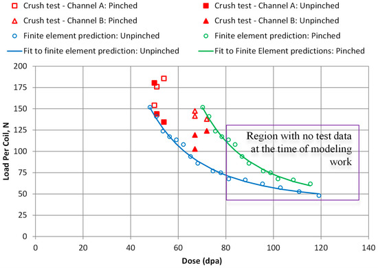
Figure 18.
Comparison of finite element predictions for optimized spacers with crush test results from ex-service spacers.
The finite element predictions were based on a mechanism where the grain boundary mechanical strength was a function of the grain boundary area coverage. The coverage calculated for the conditions specific to the spacer coil samples was predicted using the rate theory model described here.
The important result from the rate theory is the trend of grain boundary area coverage with increasing dose, exhibiting a decreasing rate of coverage with increasing dose, Figure 19. This simply identifies that the limiting factor in the evolution of the grain boundary cavity structure are the point defect fluxes from the grain interior, which are non-linear with dose. The model was compared to estimates of area coverage from various TEM samples. The observations of grain boundary coverage exhibited considerable variability. The model was therefore applied using available grain interior microstructure data that provide upper and lower bound values for sink strengths giving predictions that encompass the observations. This process was tractable for the high temperature data but not the low temperature data, for which the prediction was generated using mean values for the low temperature microstructure data.
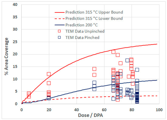
Figure 19.
Calculated He bubble coverage of grain boundaries compared with measurements. The upper-bound and lower-bound calculations for 315 °C represent the extremes of the variability in grain interior sink strength. Only one internal sink condition for 200 °C is shown as this was the only condition where a stable solution was possible.
The rate theory model output in this case served as input for the finite element model [37]. To a large extent having a mechanistic model provides confidence in extending predictions outside of the range of conditions applicable to the mechanical test data against which it is compared. The results presented here show how the model can be extended to predict grain boundary coverage by cavities over a large range of temperatures and damage rates applicable to different reactors.
3.2.1. Grain Boundary Segregation of He Bubbles
The rate theory model described in this paper has been aimed at predicting the trend in embrittlement as a function of operating time for nuclear reactor components prone to He embrittlement.
The interplay between swelling and GB perforation is such that both embrittlement and swelling are dependent on the presence of He to stabilise cavities. Without He to stabilise a large vacancy cluster (cavity), any vacancies that migrate to grain boundaries are simply absorbed and are free to migrate along the boundary until they are annihilated at a suitable sink. When He is present, vacancies are trapped and the resultant evolution of the grain boundary cavity microstructure weakens the boundary simply by reducing the coherency of the interface. There are many examples to show that cavities are absent on boundaries in electron- or self-ion-irradiated materials, for which there is no involvement of He, and are more concentrated than in the matrix when He is present (see Supplementary Material, Sections S1 and S2).
Even with He atoms available at the boundary, the extent to which cavities are segregated on the boundary is governed by the difference in the sink strength of the boundary and the sink strength of the grain interior. Typically, the dislocation microstructure evolves and reaches a steady-state condition at low doses (<5 dpa) but the cavity structure can evolve over long periods. An increase in the cavity sink strength within the grains, which is coincident with increased swelling will, in principle, interfere with the migration of point defects to grain boundaries. So, while both swelling and He embrittlement are dependent on He, the interplay between the two means that it is possible for high swelling to coincide with lower grain boundary embrittlement if the effect is to limit the flow of point defects to the boundaries. It is possible to get high swelling without He and swelling-induced embrittlement that is not inter-granular (see Supplementary Material, Section S3). In such cases there is no mechanism to stabilise cavities on grain boundaries and therefore voids can form in the matrix but not on the boundary [28].
Apart from stabilising cavities on grain boundaries, void formation without an insoluble gas such as He requires a large stochastic fluctuation so that a void embryo can form and grow by a bias-driven mechanism [3,4,5,6,7,8,9,10,11]. The stochastic fluctuation must be large enough to exceed a stability condition that applies to the arrival of a net flux of vacancies but also because any small vacancy cluster would normally collapse to form a loop. The presence of an insoluble gas, which does not necessarily have to be He, will always stabilise a cavity at some equilibrium size dependent on the temperature. The nature of He-embrittlement, which is an inter-granular failure mechanism, shows that a small amount of He is necessary, in the first instance, to stabilise cavities on grain boundaries.
Whereas dose rate has not been specifically addressed in this paper, because grain boundary coverage increases as the swelling decreases, one can deduce that temperature shifts in swelling as a result of increased dose rates should also be reflected in the temperature dependence of He embrittlement [27].
3.2.2. Inter-Granular Fracture
Inter-granular fracture is often associated with He embrittlement because of the concomitant observations of high densities of He-stabilised cavities on grain boundaries. He-embrittlement was often considered to be a high temperature phenomenon and limited to SFRs where the He generation rate is low and swelling decreases at high temperatures (>600 °C) while the He-embrittlement increases. Recent observations have indicated that He-embrittlement failures are occurring at normal power reactor operating temperatures [16,17,18,26,27,28].
That grain boundaries perforated by cavities will be weakened to some extent is understandable. The extent of coverage that leads to inter-granular failure can be deduced empirically from measurement or from finite element modelling of grain boundary cracking. Demkowicz [75], showed that grain boundary crack blunting occurs for an area coverage <18%. At higher levels he showed that brittle failure occurred and the crack advances by some mechanism akin to necking between the bubbles. A potential embrittlement mechanism is illustrated schematically in Figure 20. Subject to an applied stress Figure 20a,b show how a grain boundary crack is blunted by plastic deformation that occurs preferentially at the crack tip because of stress intensification at this location. When cavities are present slip opens the side of the cavity closest to the crack tip and a hinge is created at the opposite side of the cavity, Figure 19c,d, thus providing a mechanism for easy advancement of the crack without the blunting that would normally occur.
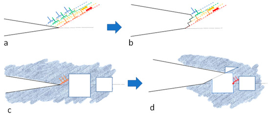
Figure 20.
Schematic diagram illustrating the possible effect of a having high density of grain boundary cavities on inter-granular fracture: (a) grain boundary crack that emits dislocations; (b) crack blunting effect when the deformation at the crack tip is unconstrained; (c) crack on a perforated boundary emitting dislocations; (d) dislocations have to cut through the nearest cavity, effectively blunting the crack, and create a hinge that re-centres the deformation on the grain boundary.
4. Conclusions
For austenitic alloys in fast reactors such as EBR2 rate theory shows that the swelling regime extends from about 250 °C to 700 °C with a peak swelling at 500 °C of about 40% at 100 dpa. In high thermal fluxes He production extends the swelling regime to temperatures higher than 700 °C. The start of the swelling regime shifts by about 50 °C to slightly lower temperatures (200 °C) in thermal power reactors. The peak swelling at 500 °C increases up to about 60% at 100 dpa. He production in HWRs and high flux reactors such as HFIR promotes more swelling at high temperatures with upticks in swelling rates relative to EBR2 at temperatures ranging from 550 °C to 650 °C.
Using a rate theory model validated against swelling data from EBR2 the accumulation of He-stabilised cavities on grain boundaries with increasing dose show that the rate of coverage is non-linear and decreases with increasing in-reactor exposure.
The propensity for increased grain boundary coverage in Ni-containing alloys in HWRs can be largely attributed to the high He production rates in these reactors stemming from the absorption of thermal neutrons by 58Ni creating 59Ni, which has a high (n,α) reaction cross-section with thermal neutrons.
With respect to grain boundary coverage there are two regimes to consider: (i) bubble, (ii) void. The void regime refers to the situation where He-stabilised cavities exhibit bias-driven growth. In the bubble regime the extent of interface coverage at a given dose increases with increasing temperature. In the “void” regime, the extent of interface coverage is relatively insensitive to temperature but mirrors the swelling such that less swelling corresponds to a higher grain boundary coverage.
Supplementary Materials
The following supporting information can be downloaded at: https://www.mdpi.com/article/10.3390/met12101692/s1, Figure S1: A comparison of fracture surfaces of Inconel X-750 spring material after crush testing to failure at room temperature. The unirradiated materials exhibits conventional ductile cup-cone fracture. The material irradiated in a CANDU reactor to dose of about 50 DPA at a nominal (estimated) temperature of 315 °C exhibits inter-granular failure. Figure S2. Over-focussed image showing cavities segregated on a grain boundary (arrowed) in Inconel X-750 after irradiation in a CANDU reactor to about 23 dpa at a temperature of about 315 °C. Figure S3. (a) Fracture surface showing inter-granular failure of 316 SS irradiated to 80 DPA at 320 °C and tested in PWR water chemistry at 55% of the irradiated yield, modified from [55]; and (b) TEM micrograph showing grain boundary cavity segregation in 316 SS irradiated in a PWR at 315 °C to 70 dpa and 625 appm He, modified from [56]. Figure S4. Room temperature stress-strain curves for Inconel 718 material extracted from the LANSCE window and irradiated at a temperature between 367 °C and 400 °C. Reproduced with permission from [58]. Figure S5. Room temperature stress-strain curves for ferritic V-15Cr-5Ti material irradiated in FFTF to various dose levels. Modified from [59]. Figure S6. (a) Brittle intergranular fracture surface for a V-15Cr-5Ti specimen containing 300 appm He that was irradiated in FFTF to 17 dpa at 420 °C and tested in tension at 420 °C; (b) grain boundary bubbles in a V-15Cr-5Ti specimen with 74 appm He after irradiation in FFTF to 40 dpa at 520 °C. Modified from [59]. Figure S7. Voids in ion-irradiated materials: (a) Voids in MA957 ferritic alloy (Fe–14 wt%Cr, 0.9% Ti, 0.3% Mo) after Fe-ion irradiation to 500 dpa at 450°C—No He is produced and no grain boundary segregation, modified from [60]; (b) AISI 316 SS tested in tension to rupture at 1023K during He-ion irradiation; [He] = 2500 appm He: mean bubble diameter: 50 nm, modified from [53]. Figure S8. Fracture surface in an Fe–18Cr–10Ni–Ti austenitic stainless steel tensile specimen after testing at a swelling level of 30%. Modified from [61]. Figure S9. (a) Fracture surface of failed cold-worked creep tube at 365 °C and 83 dpa, showing ductile coalescence of voids parallel to grain boundaries; (b) Large voids associated with cracking along denuded zone adjacent to grain boundaries at 335 °C and 73 dpa in an annealed stress-free tube. Modified from [62]. Figure S10. TEM micrographs of Inconel X-750 material irradiated to ~55 dpa, ~18,000 appm He at about 315 °C, showing planar sub-grain boundaries (possibly incoherent twins or ε-martensite platelets) covered with helium bubbles (arrowed). Modified from [65]. Figure S11. Composition profiles across a grain boundary in a neutron-irradiated 300-series stainless steel and corresponding TEM image with boundary. Modified from [67]. Figure S12. Dose dependence of grain boundary chromium concentration for several 300-series austenitic stainless steels irradiated at temperatures about 300 °C. Reproduced with permission from [69].
Author Contributions
Conceptualization, M.G., S.X., J.E.R.N.; methodology, M.G., S.X., J.E.R.N.; software, M.G., S.X.; validation, M.G., S.X., J.E.R.N.; formal analysis, M.G.; investigation, M.G.; resources, M.G., S.X., J.E.R.N.; data curation, M.G., S.X., J.E.R.N.; writing—original draft preparation, M.G.; writing—review and editing, M.G., S.X., J.E.R.N.; visualization, M.G.; supervision, M.G.; project administration, M.G.; funding acquisition, M.G. All authors have read and agreed to the published version of the manuscript.
Funding
This research received no external funding.
Data Availability Statement
Not applicable.
Conflicts of Interest
The authors declare no conflict of interest.
Abbreviations
| appm | atomic parts per million |
| at% | atomic% |
| BOR | a series of Russian test reactors |
| BWR | boiling water reactor |
| CANDU | a trademark of Atomic Energy of Canada Limited |
| CW | cold-worked |
| DPA or dpa | displacements per atom |
| EBR2 | experimental breeder reactor 2 |
| FCC | face-centered-cubic |
| FMD | freely migrating defects |
| FPY | full power years |
| FT | flux thimble |
| HCP | hexagonal-close-packed |
| HFIR | high flux isotope reactor |
| HWR | heavy water reactor |
| IASCC | irradiation assisted stress-corrosion-cracking |
| IGSCC | inter-granular stress-corrosion-cracking |
| INCONEL | a trademark of the special metals company |
| LMR | liquid metal (fast) reactor |
| LWR | light water reactor |
| ORNL | Oak Ridge National Laboratory |
| PKA | primary knock-on atom |
| PWR | pressurized water reactor |
| PV | pressure vessel |
| SEM | scanning electron microscope (or microscopy) |
| SFR | sodium fast reactor |
| SPECTER | a code for calculating DPA for various elements |
| SS | stainless steel |
| TDAM | energy available for creating atomic displacements for a given PKA |
| TEM | transmission electron microscope or microscopy |
| UTS | ultimate tensile strength |
| wtppm | parts per million by weight |
| wt% | weight % |
| YS | yield strength |
References
- Bhattacharya, A.; Zinkle, S.J. Cavity Swelling in Irradiated Materials. In Comprehensive Nuclear Materials, 2nd ed.; Konings, R.J.M., Stoller, R.E., Eds.; Elsevier: Oxford, UK, 2020; Chapter 12; Volume 1, pp. 406–455. [Google Scholar]
- Phillipps, K.; Sonnenberg, K. Interstitial Diffusion of He in Nickel. J. Nucl. Mater. 1983, 114, 95–97. [Google Scholar] [CrossRef]
- Phillipps, K.; Sonnenberg, K.; Williams, J.M. Diffusion of He in Nickel. J. Nucl. Mater. 1982, 107, 271–279. [Google Scholar] [CrossRef]
- Trinkaus, H.; Singh, B.N. Helium accumulation in metals during irradiation–Where do we stand? J. Nucl. Mater. 2003, 323, 229–242. [Google Scholar] [CrossRef]
- Adams, J.B.; Wolfer, W.G. On the diffusion mechanisms of helium in nickel. J. Nucl. Mater. 1988, 158, 25–29. [Google Scholar] [CrossRef]
- Hepburn, D.J.; Ferguson, D.; Gardner, S.; Ackland, G.J. First-principles study of helium, carbon, and nitrogen in austenite, dilute austenitic iron alloys, and nickel. Phys. Rev. B 2013, 88, 024115. [Google Scholar] [CrossRef]
- Mansur, L.K.; Yoo, M.H. Advances in the theory of swelling in irradiated metals and alloys. J. Nucl. Mater. 1979, 85–86, 523–532. [Google Scholar] [CrossRef]
- Mansur, L.K.; Coghlan, W.A. Mechanisms of helium interaction with radiation effects in metals and alloys: A review. J. Nucl. Mater. 1983, 119, 1–25. [Google Scholar] [CrossRef]
- Hishinuma, A.; Mansur, L.K. Critical radius for bias-driven swelling—A further analysis and its application to bimodal cavity size distributions. J. Nucl. Mater. 1983, 118, 91–99. [Google Scholar] [CrossRef]
- Coghlan, W.A.; Mansur, L.K. Critical radius and critical number of gas atoms for cavities containing a Van der Waals gas, for bias-driven swelling—A further analysis and its application to bimodal cavity size distributions. J. Nucl. Mater. 1984, 122–123, 495–501. [Google Scholar] [CrossRef]
- Stoller, R.E.; Odette, G.R. Analytical Solutions for Helium Bubble and Critical Radius Parameters Using a Hard Sphere Equation of State. J. Nucl. Mater. 1985, 131, 118–125. [Google Scholar] [CrossRef]
- Stoller, R.E.; Odette, R.G. A Comparison of the Relative Importance of Helium and Vacancy Accumulation in Void Nucleation. In Proceedings of the 13th International Symposium on Radiation Induced Changes in Microstructure, Seattle, WA, USA, 23–25 June 1986; Garner, F.A., Packan, N.H., Kumar, A.S., Eds.; ASTM STP 955, Part I. ASTM: Philadelphia, PA, USA, 1987; pp. 358–370. [Google Scholar]
- Stoller, R.E.; Odette, R.G. A Composite Model of Microstructure Evolution in Austenitic Steels Under Fast Neutron Irradiation. In Proceedings of the 13th International Symposium on Radiation Induced Changes in Microstructure, Seattle, WA, USA, 23–25 June 1986; Garner, F.A., Packan, N.H., Kumar, A.S., Eds.; ASTM STP 955, Part I. ASTM: Philadelphia, PA, USA, 1987; pp. 371–392. [Google Scholar]
- Mansur, L.K. Theory and experimental background on dimensional changes in irradiated alloys. J. Nucl. Mater. 1994, 216, 97–123. [Google Scholar] [CrossRef]
- Golubov, S.I.; Barashev, A.V.; Stoller, R.E. Radiation damage theory. In Comprehensive Nuclear Materials, 1st ed.; Elsevier Inc.: Amsterdam, The Netherlands, 2012; pp. 357–391. [Google Scholar] [CrossRef]
- Griffiths, M. Effect of Neutron Irradiation on the Mechanical Properties, Swelling and Creep of Austenitic Stainless Steels. Materials 2021, 14, 2622. [Google Scholar] [CrossRef] [PubMed]
- Griffiths, M.; Ramos-Nervii, J.; Greenwood, L.R. A Rate Theory Model of Radiation-Induced Swelling in an Austenitic Stainless Steel. J. Nucl. Eng. 2021, 2, 34. [Google Scholar] [CrossRef]
- Judge, C.D.; Rajakumar, H.; Korinek, A.; Botton, G.; Cole, J.; Madden, J.W.; Jackson, J.H.; Freyer, P.D.; Giannuzzi, A.L.; Griffiths, M. High Resolution Transmission Electron Microscopy of Irradiation Damage in Inconel X-750. In The Minerals, Metals & Materials Series, Proceedings of the 18th International Conference on Environmental Degradation of Materials in Nuclear Power Systems–Water Reactors, Oregon, Portland, 13–17 August 2017; Springer: Cham, Switzerland, 2018. [Google Scholar] [CrossRef]
- Griffiths, M.; Walters, L.; Greenwood, L.R.; Garner, F.A. Accelerated materials evaluation for nuclear applications. J. Nucl. Mater. 2017, 488, 46–62. [Google Scholar] [CrossRef]
- Greenwood, L.R. A new calculation of Thermal Neutron Damage and Helium Production in Nickel. J. Nucl. Mater. 1983, 115, 137–142. [Google Scholar] [CrossRef]
- Greenwood, L.R.; Garner, F.A. Hydrogen Generation Arising from the 59Ni (n,p) Reaction and its impact on Fission-Fusion Correlations. J. Nucl. Mater. 1996, 233–237, 1530–1534. [Google Scholar] [CrossRef]
- Greenwood, L.R.; Smither, R.K. SPECTER: Neutron Damage Calculations for Materials Irradiations, ANL/FPP/TM-197, Argonne National Laboratory. 1985. Available online: https://www-nds.iaea.org/irdf2002/codes/index.htmlx (accessed on 10 March 2014).
- MacFarlane, R.E.; Muir, D.W.; Mann, F.M. Radiation Damage Calculations with NJOY. J. Nucl. Mater. 1984, 122–123, 1041. Available online: http://t2.lanl.gov/nis/ (accessed on 2 June 2017). [CrossRef][Green Version]
- ENDF/B-VI Nuclear Library. Available online: http://t2.lanl.gov/nis/data.shtml (accessed on 10 March 2014).
- Was, G.S. Fundamentals of Radiation Materials Science: Metals and Alloys, 2nd ed.; Springer: New York, NY, USA, 2017. [Google Scholar]
- Griffiths, M. The Effect of Irradiation on Ni-containing Components in CANDU Reactor Cores: A Review. AECL Nucl. Rev. 2013, 2, 1–16, Erratum in AECL Nucl. Rev. 2014, 3, 89. [Google Scholar] [CrossRef]
- Griffiths, M. Ni-Based Alloys for Reactor Internals and Steam Generator Applications, Chapter 9. In Structural Alloys for Nuclear Energy Applications; Zinkle, S., Odette, R., Eds.; Elsevier: Amsterdam, The Netherlands, 2019; ISBN 9780123970466. [Google Scholar]
- Griffiths, M.; Boothby, R. Radiation Effects in Nickel-Based Alloys. In Reference Module in Materials Science and Materials Engineering; Comprehensive Nuclear Materials; Konings, R., Ed.; Elsevier: Amsterdam, The Netherlands, 2020; pp. 334–371. [Google Scholar]
- Stoller, R.E.; Greenwood, L.R. An Evaluation of Through-Thickness Changes in Primary Damage Production in Commercial Reactor Pressure Vessels. Effects of Radiation on Materials: 20th International Symposium; ASTM STP, 1405; Rosinski, S.T., Grossbeck, M.L., Allen, T.R., Kumar, A.S., Eds.; American Society for Testing and Materials: West Conshohocken, PA, USA, 2002. [Google Scholar]
- Gao, F.; Wooding, S.J.; Calder, A.F.; Bacon, D.J. Computer Simulation of Displacement Cascade Damage in Metals. Mat. Res. Soc. Symp. Proc. 1995, 373, 15. [Google Scholar] [CrossRef]
- Okamoto, P.R.; Rehn, L.E.; Averback, R.S. Effects of Primary Recoil Energy on the Production Rate of Mobile Defects During Elevated Temperature Irradiation. J. Nucl. Mater. 1985, 133–134, 373–377. [Google Scholar] [CrossRef][Green Version]
- Trinkaus, H.; Naundorf, V.; Singh, B.N.; Woo, C.H. On the experimental-determination of the migrating defect fraction under cascade damage conditions. J. Nucl. Mater. 1994, 210, 244–253. [Google Scholar] [CrossRef]
- Kwon, J.; Motta, A.T. Role of Radiation in BWR Core Shroud Cracking, Reactor Dosimetry; ASTM STP, 1398; Williams, J.G., Vehar, D.W., Ruddy, F.H., Gilliam, D.M., Eds.; American Society for Testing and Materials: West Conshohocken, PA, USA, 2000. [Google Scholar]
- Svetukhin, V.; Tikhonchev, M. Effective Atomic Displacements in α-Zirconium under Neutron Irradiation. Adv. Mater. Res. 2014, 1042, 52–57. [Google Scholar] [CrossRef]
- Ziegler, J.F.; Ziegler, M.; Biersack, J. SRIM—The stopping and range of ions in matter. Nucl. Instrum. Methods Phys. Res. Sect. B 2010, 268, 1818. [Google Scholar] [CrossRef]
- Nordlund, K.; Zinkle, S.J.; Sand, A.E.; Granberg, F.; Averback, R.S.; Stoller, R.E.; Suzudo, T.; Malerba, L.; Banhart, F.; Weber, W.J.; et al. Primary radiation damage: A review of current understanding and models. J. Nucl. Mater. 2018, 512, 450–479. [Google Scholar] [CrossRef]
- Xu, S.X.; Griffiths, M.; Scarth, D.A.; Graham, D. Microstructure-based Polycrystalline Finite Element Modeling of Inconel X-750 Irradiated in a CANDU Reactor. Eng. Fract. Mech. 2022. accepted. [Google Scholar]
- Olander, D.R. Fundamental Aspects of Nuclear Reactor Fuel Elements; TID 26711-Part 1; Technical Information Center, Office of Public Affairs, Energy Research and Development Administration: Washington, DC, USA, 1976. [Google Scholar]
- Heald, P.T.; Speight, M.V. Point Defect Behaviour in Irradiated Materials. Acta. Metall. 1975, 23, 1389. [Google Scholar] [CrossRef]
- Kohnert, A.A.; Cusentino, M.A.; Wirth, B.D. Molecular statics calculations of the biases and point defect capture volumes of small cavities. J. Nucl. Mater. 2018, 499, 480–489. [Google Scholar] [CrossRef]
- Heald, P.T.; Harbottle, J.E. Irradiation Creep due to Dislocation Climb and Glide. J. Nucl. Mater. 1977, 67, 229–233. [Google Scholar] [CrossRef]
- Harkness, S.D.; Li, C.Y. A Study of Void Formation in Fast Neutron-Irradiated Metals. Met. Trans. 1971, 2, 1457–1470. [Google Scholar] [CrossRef]
- Luo, J.; Xin, Y.; Sun, Z.; Li, Y.; Zhu, Y.; Chen, P. Formulation of voids and bubbles as biased sinks to crystalline point defects. Scripta Mater. 2021, 197, 113806. [Google Scholar] [CrossRef]
- Nabarro, F.R.N. Deformation of Crystals by the Motion of Single Point Defects; Report Conf. on Strength of Solids; The Physical Society: London, UK, 1948; Volume 75. [Google Scholar]
- Herring, C. Diffusional Viscosity of a Polycrystalline Solid. J. Appl. Phys. 1950, 21, 437. [Google Scholar] [CrossRef]
- Edwards, D.J.; Simonen, E.P.; Bruemmer, S.M.; Efsing, P. Microstructural evolution in neutron-irradiated stainless steels: Comparison of LWR and fast-reactor irradiations. In Proceedings of the 12th International Conference on Environmental Degradation of Materials in Nuclear Power System—Water Reactors, Salt Lake City, UT, USA, 14–18 August 2005; pp. 419–428. [Google Scholar]
- Garner, F.A. Radiation-Induced Damage in Austenitic Structural Steels Used in Nuclear Reactors. In Reference Module in Materials Science and Materials Engineering, 2nd ed.; Comprehensive Nuclear Materials; Konings, R., Stoller, R., Eds.; Elsevier: Oxford, UK, 2020; Volume 3, Chapter 2; pp. 57–168. [Google Scholar]
- Maziasz, P.J. Swelling and Microstructure of HFIR Irradiated Austenitic Stainless Steels, United States. 1980. Available online: https://www.osti.gov/servlets/purl/6143016 (accessed on 5 August 2022).
- Maziasz, P.J.; Grossbeck, M.L. Swelling, microstructural development and helium effects in type 316 stainless steel irradiated in HFIR and EBR-II. J. Nucl. Mater. 1981, 104, 987–991. [Google Scholar] [CrossRef][Green Version]
- Grossbeck, M.L.; Ehrlich, K.; Wassilew, C. An assessment of tensile, irradiation creep, creep rupture, and fatigue behavior in austenitic stainless steels with emphasis on spectral effects. J. Nucl. Mater. 1990, I74, 264–281. [Google Scholar] [CrossRef]
- Mansur, L.K.; Lee, E.H.; Maziasz, P.J.; Rowcliffe, A.P. Control of Helium effects in Irradiated Materials based on Theory and Experiment. J. Nucl. Mater. 1986, 141–143, 633–646. [Google Scholar] [CrossRef]
- Kramer, D.; Brager, H.R.; Rhodes, C.G.; Pard, A.G. Helium embrittlement in type 304 stainless steel. J. Nucl. Mater. 1968, 25, 121–131. [Google Scholar] [CrossRef]
- Schroeder, H.; Batfalsky, P. The dependence of the high temperature mechanical properties of austenitic stainless steels on implanted helium. J. Nucl. Mater. 1983, 115, 297–306. [Google Scholar] [CrossRef]
- Fujimoto, K.; Yonezawa, T.; Wachi, E.; Yamaguchi, Y.; Nakano, M.; Shogan, R.P.; Massoud, J.P.; Mager, T.R. Effect of the accelerated irradiation and hydrogen/helium gas on IASCC characteristics for highly irradiated austenitic stainless steels. In Proceedings of the 12th International Conference on Environmental Degradation of Materials in Nuclear Power System—Water Reactors, Salt Lake City, UT, USA, 14–18 August 2005; pp. 299–310. [Google Scholar]
- Bosch, R.W.; Vankeerberghen, M.; Gérard, R.; Somville, F. Crack initiation testing of thimble tube ma-terial under PWR conditions to determine a stress threshold for IASCC. J. Nucl. Mater. 2015, 461, 112–121. [Google Scholar] [CrossRef]
- Edwards, D.J.; Garner, F.A.; Bruemmer, S.M.; Efsing, P. Nano-cavities observed in a 316 SS PWR flux thimble tube irradiated to 33 and 70 dpa. J. Nucl. Mater. 2009, 384, 249–255. [Google Scholar] [CrossRef]
- Carsughi, F.; Derz, H.; Pott, G.; Sommer, W.; Ullmaier, H. Investigations on Inconel 718 Irradiated with 800 MeV Protons. J. Nucl. Mater. 1999, 264, 78–88. [Google Scholar] [CrossRef]
- James, M.R.; Maloy, S.A.; Gac, F.D.; Sommer, W.F.; Chen, J.; Ullmaier, H. The mechanical Properties of an Alloy 718 Window after Irradiation in a Spallation Environment. J. Nucl. Mater. 2001, 296, 139–144. [Google Scholar] [CrossRef]
- Braski, D.N. The effect of neutron irradiation on vanadium alloys. J. Nucl. Mater. 1986, 141–143, 1125–1131. [Google Scholar] [CrossRef]
- Toloczko, M.B.; Garner, F.A.; Voyevodin, V.N.; Bryk, V.V.; Borodin, O.V.; Melnychenko, V.V.; Kalchenko, A.S. Ion-Induced Swelling of ODS Ferritic Alloy MA957 Tubing to 500 dpa. J. Nucl. Mater. 2014, 453, 323–333. [Google Scholar] [CrossRef]
- Neustroev, V.S.; Garner, F.A. Severe embrittlement of neutron irradiated austenitic steels arising from high void swelling. J. Nucl. Mater. 2009, 386, 157–160. [Google Scholar] [CrossRef]
- Porollo, S.I.; Vorobjev, A.N.; Konobeev, Y.V.; Dvoriashin, A.M.; Krigan, V.M.; Budylkin, N.I.; Mironova, E.G.; Garner, F.A. Swelling and void-induced embrittlement of austenitic stainless steel irradiated to 73–82 dpa at 335–365 °C. J. Nucl. Mater. 1998, 258, 1613–1617. [Google Scholar] [CrossRef]
- Hamilton, M.L.; Huang, F.H.; Yang, W.J.; Garner, F.A. Mechanical properties and fracture behavior of 20% cold-worked 316 stainless steel irradiated to very high neutron exposures. In Influence of Radiation on Material Properties, Proceedings of the 13th International Symposium (Part II); ASTM International: West Conshohocken, PA, USA, 1987; pp. 245–270. [Google Scholar]
- Rowcliffe, A.F.; Mansur, L.K.; Hoelzer, D.T.; Nanstad, R.K. Perspectives on Radiation Effects in Nickel-Base Alloys for Applications in Advanced Reactors. J. Nucl. Mater. 2009, 392, 341–352. [Google Scholar] [CrossRef]
- Judge, C.D. The Effects of Irradiation on Inconel X-750. Ph.D. Thesis, McMaster University, Hamilton, ON, Canada, November 2015. Available online: https://macsphere.mcmaster.ca/handle/11375/18091 (accessed on 9 September 2022).
- Was, G.S.; Busby, J.; Andresen, P.L. Effect of Irradiation on Stress Corrosion Cracking and Corrosion in Light Water Reactors. ASM Handb. Corros. Environ. Ind. 2006, 13C, 386–414. [Google Scholar]
- Bruemmer, S.M.; Simonen, E.P.; Scott, P.M.; Andresen, P.L.; Was, G.S.; Nelson, J.L. Radiation-induced material changes and susceptibility to intergranular failure of light-water-reactor core internals. J. Nucl. Mater. 1999, 274, 299–314. [Google Scholar] [CrossRef]
- Zhao, S.; Egami, T.; Stocks, G.M.; Zhang, Y. Effect of d electrons on defect properties in NiCoCr and NiCoFeCr concentrated solid solution alloys. Phys. Rev. Mater. 2018, 2, 013602. [Google Scholar] [CrossRef]
- Andresen, P.L.; Was, G.S. Irradiation Assisted Stress Corrosion Cracking, Comprehensive Nuclear Materials, 2nd ed.; Konings, R.J.M., Stoller, R.E., Eds.; Elsevier: Amsterdam, The Netherlands, 2019; Chapter 4.07; pp. 190–217. [Google Scholar]
- Fournier, L.; Sencer, B.L.; Was, G.S.; Simonen, E.P.; Bruemmer, S.M. The influence of oversized solute additions on radiation-induced changes and post-irradiation intergranular stress corrosion cracking behavior in high-purity 316 stainless steels. J. Nucl. Mater. 2003, 321, 192–209. [Google Scholar] [CrossRef]
- Schroeder, H.; Braski, D.N. The effect of implanted helium on the high temperature mechanical properties of a model austenitic Fe-17% Cr-17% Ni alloy. J. Nucl. Mater. 1983, 117, 287–294. [Google Scholar] [CrossRef]
- Schroeder, H. High temperature helium embrittlement in austenitic stainless steels correlations between microstructure and mechanical properties. J. Nucl. Mater. 1988, 155–157, 1032–1037. [Google Scholar] [CrossRef]
- Schroeder, H.; Dai, Y. Helium concentration dependence of embrittlement effects in DIN 1.4970, 13% cw austenitic stainless steel at 873 K. J. Nucl. Mater. 1992, 191–194, 781–785. [Google Scholar] [CrossRef]
- Dai, Y.; Odette, G.R.; Yamamoto, T. The Effects of Helium in Irradiated Structural Alloys, Chapter 1.07. In Basic Aspects of Radiation Effects in Solids/Basic Aspects of Multi-Scale Modeling, 2nd ed.; Comprehensive Nuclear Materials; Konings, R.J.M., Stoller, R.E., Eds.; Elsevier: Amsterdam, The Netherlands, 2020; pp. 186–234. [Google Scholar]
- Demkowicz, M.J. A threshold density of helium bubbles induces a ductile-to-brittle transition at a grain boundary in nickel. J. Nucl. Mater. 2020, 533, 152118. [Google Scholar] [CrossRef]


Publisher’s Note: MDPI stays neutral with regard to jurisdictional claims in published maps and institutional affiliations. |
© 2022 by the authors. Licensee MDPI, Basel, Switzerland. This article is an open access article distributed under the terms and conditions of the Creative Commons Attribution (CC BY) license (https://creativecommons.org/licenses/by/4.0/).