Article

Mechanism Study of the Effect of Selective Laser Melting Energy Density on the Microstructure and Properties of Formed Renewable Porous Bone Scaffolds

1
School of Materials Science and Engineering, Shandong Jianzhu University, Jinan 250101, China
2
State Key Laboratory of Materials Processing and Die & Mould Technology, Huazhong University of Science and Technology, Wuhan 430074, China
*
Author to whom correspondence should be addressed.
Metals 2022, 12(10), 1712; https://doi.org/10.3390/met12101712
Submission received: 1 September 2022 / Revised: 7 October 2022 / Accepted: 9 October 2022 / Published: 13 October 2022

Abstract

:
To investigate the effect of selective laser melting (SLM) energy densities on the performance of porous 316L stainless steel bone scaffolds, the porous bone scaffolds with a face-centered cubic (FCC) structure were prepared using SLM technology, and a comprehensive study combining finite element analysis (FEA) and experiments was conducted on the SLM-formed 316L porous bone scaffolds. The mechanism of how various energy densities affect bone scaffolds were identified, and the effects of different energy densities on the primary dendrite spacing, grain orientation, residual stress, and transient melt pool variation in the scaffolds were discussed and summarized. It was found that the change in the energy densities had a more serious effect on the primary dendrite spacing, with the primary dendrite spacing increasing from 320 to 501 nm when the energy densities were increased from 41.7 to 111.1 J/mm3. In addition, analysis of the residual stress in the formed scaffolds showed that when an energy density of 41.7 J/mm3 was chosen for construction, the internal residual stress in the scaffolds reached a minimum value of 195.78 MPa, a reduction of approximately 36.6% compared to that of 111.1 J/mm3 for the porous scaffold. For the other properties of the scaffolds, the choice of low energy densities for the construction of FCC-structured porous bone scaffolds allowed for a maximum 10% reduction in the controlled deformation and a maximum 17% increase in the compressive properties. At the same time, it was found that the analysis results of the SLM-forming process by the FEA method were consistent with the experimental results. The main innovation of this paper is the proposal of the best construction parameters for porous bone scaffolds with an FCC structure formed by SLM and verification of the rationality of the best parameters through macro and micro experimental analysis, which guides the construction of porous bone scaffolds with an FCC structure formed by additive manufacturing. In addition, this study used finite element simulation to analyze the SLM process. This provides early prediction, optimization, and improvement for SLM-forming FCC porous bone scaffolds. The most important thing is that FEA can be used to more rapidly and economically analyze SLM. In the future, FEA can be used to provide a reference for porous bone scaffolds with different structures, different construction energy densities, different materials, and additive manufacturing in other industries.

1. Introduction

SLM technology has received a great deal of attention and application in many fields such as engineering and biomedicine due to its ability to produce high-precision, high-density, and high-performance metal parts [1,2,3]. SLM offers the advantage of being precisely customizable and is also capable of being formed in a single pass for extremely complex metal parts that can be put to use directly after a simple post-treatment process. Many metallic biomaterials, such as Ti, Ta, and 316L stainless steel, are currently used in the manufacture of surgical tools and medical implants through SLM technology due to their excellent biocompatibility [4], high fracture toughness [5], adjustable stiffness to match the host tissue, and high wear and corrosion resistance [6]. However, many obstacles must be overcome before SLM technology can become a key research and development process in the biomedical field, the biggest of which is the relationship between process parameters and the final service performance of SLM-manufactured parts. It has been reported that up to hundreds of factors can influence the quality of additively manufactured parts [7,8] and that the selection of appropriate process parameters (e.g., energy density, build orientation, scanning strategy) plays a critical role in determining the final performance.
In the field of bone tissue engineering, changes in the manufacturing process [9,10], materials [10,11], and structural shape [12,13] of porous bone scaffolds can achieve maximum optimization for the fatigue strength, elastic modulus, and yield strength of bone scaffolds, and, together with the corresponding biomedical experiments, greatly facilitate the application of artificial porous bone scaffolds. Jaroslav et al. [14] formed 316L stainless steel scaffolds using the SLM technique, affirming SLM is a suitable technique for the preparation of highly porous implants from 316L stainless steel in terms of the mechanical properties and biocompatibility. Zhu et al. [15] found that the degree of densification of SLM parts was increased by varying the forming process parameters, thereby improving the wear resistance. E. Liverani et al. [9] found that the laser power of SLM had the greatest effect on the part density while the hatching spacing and building orientation did not have a significant effect in the range tested. Yadollahi et al. [16] found that the construction process parameters play a decisive role in the thermal cycling during the forming process, which in turn affects the tissue structure and thus the mechanical strength. Wang [17] and others have pointed out that the thermal cycling generated by the rapid melting-solidification characteristics of SLM technology can lead to the accumulation of residual stress within the fabricated part, which can lead to deformation and negatively affect the performance of the part. Mahyar et al. [18] found that by establishing the relationship between the processing parameters, laser absorption rate, and dynamic changes in the melt pool, the selection of optimal processing parameters in laser processing can achieve the effect of controlling the induced heat and reducing the thermal residual stress. Mercelis et al. [19] found that the material properties, sample and substrate height, laser scanning strategy, and heating conditions were the most important parameters determining the magnitude and shape of the residual stress distribution in the fabricated part. In addition, some scholars have found in their research that although the parts formed by SLM technology show improvements in terms of the yield strength, etc., there is a decrease in the elongation. To address this phenomenon, Song [20] and Ab [21] have pointed out that the porosity and denseness caused by the forming process are important factors affecting ductility while the increase in the mechanical strength is related to the degree of grain refinement and high dislocation density. Zhou et al. [22] studied the multi-scale relationship between the curvature, microstructure, and fatigue properties of curved parts manufactured by additive manufacturing and found that the workpiece with a large curvature has a lower fatigue life while the workpiece with a small curvature has a higher forming quality and ideal grain structure. This provides a theoretical basis for the fatigue performance of the formed parts. Xu et al. [23] focused on the performance of the body-centered cubic porous bone scaffold and concluded that the use of a low energy density can reduce the defects in the formed parts and control the residual stress at a lower level.
The existing research on SLM technology in biomedicine has focused on the structure and performance of porous bone scaffolds, but there has not been much detailed research on whether different structures of porous bone scaffolds need to be built with specific processing parameters, whether the processing parameters chosen for different structures have the same effect on the quality of the scaffold, the mechanism of influence and the defect prevention mechanism, and the types of defects that tend to occur in the construction of certain structures and the types of defects that are likely to occur in the construction of certain structures. Furthermore, their elimination methods have not been studied in much detail. Manufacturing defects in additive manufacturing cannot be completely avoided, but significant improvements in defects can be achieved by optimally adjusting various machining parameters and processing conditions. Sara et al. [24] found through their research on SLM that by designing and fabricating several benchmark artifacts, the most appropriate design for the desired part can be ensured in the SLM manufacturing process, which has important implications for improving additive manufactured parts in biomedical applications. In this paper, the effect of different process parameters on the melt pool was investigated through a combination of FEA and experimental methods to study the effect of SLM formation on porous bone scaffolds with an FCC structure and to explore the law of grain structure development in the melt pool. This study aimed to better understand the influence of the temperature field, melt pool flow, melt pool grain, and the distribution and evolution of residual stress in the scaffolds on the microstructure and properties during the processing of 316L stainless steel to obtain porous bone scaffolds of high-performance 316L stainless steel.

2. Experiment Work

2.1. Powder Materials

In this study, 316L pellets obtained by argon atomization were used as the original material (Figure 1) and its main chemical composition is shown in Table 1. The 316L pellets are mainly spherical in shape and their particle size is mainly distributed between 11 and 45 μm. The average particle size was 27 μm.

2.2. Model

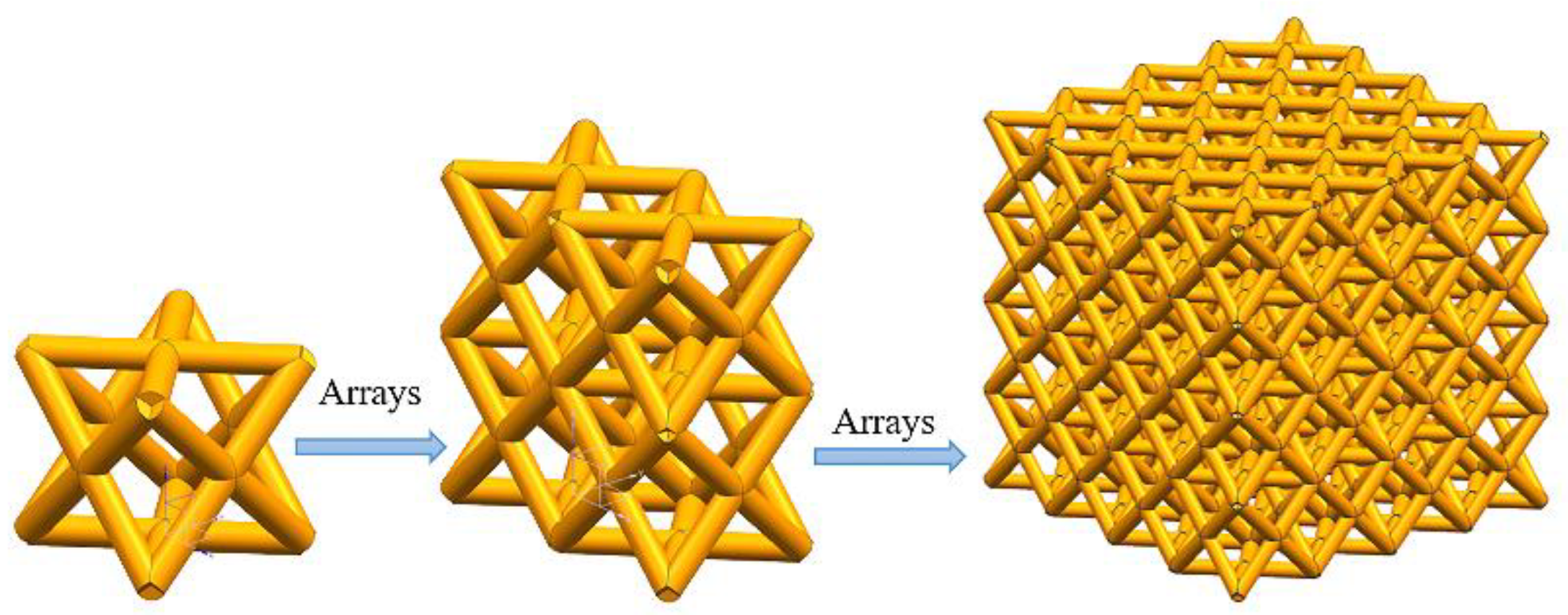
At present, there have been many studies on porous scaffold structures, such as body-centered cubic (BCC) [18,25], three-cycle minimal surface [19,26], and column and face-centered cubic structures [20,27], which can meet the requirements of human bone implants by adjusting the design parameters such as porosity and pore diameter. The diagonal design of the face-centered cubic structure has a higher bending stiffness, especially torsional stiffness, than other structures. This scaffold was designed with 85% porosity and a 900 μm pore size [21,28]. The model is constructed as shown in Figure 2 (consisting of 4 × 4 × 4 cells), using an array method to replicate the individual cells, which in turn form the dimensions required for experimental or engineering purposes.

2.3. Experimental Program Design

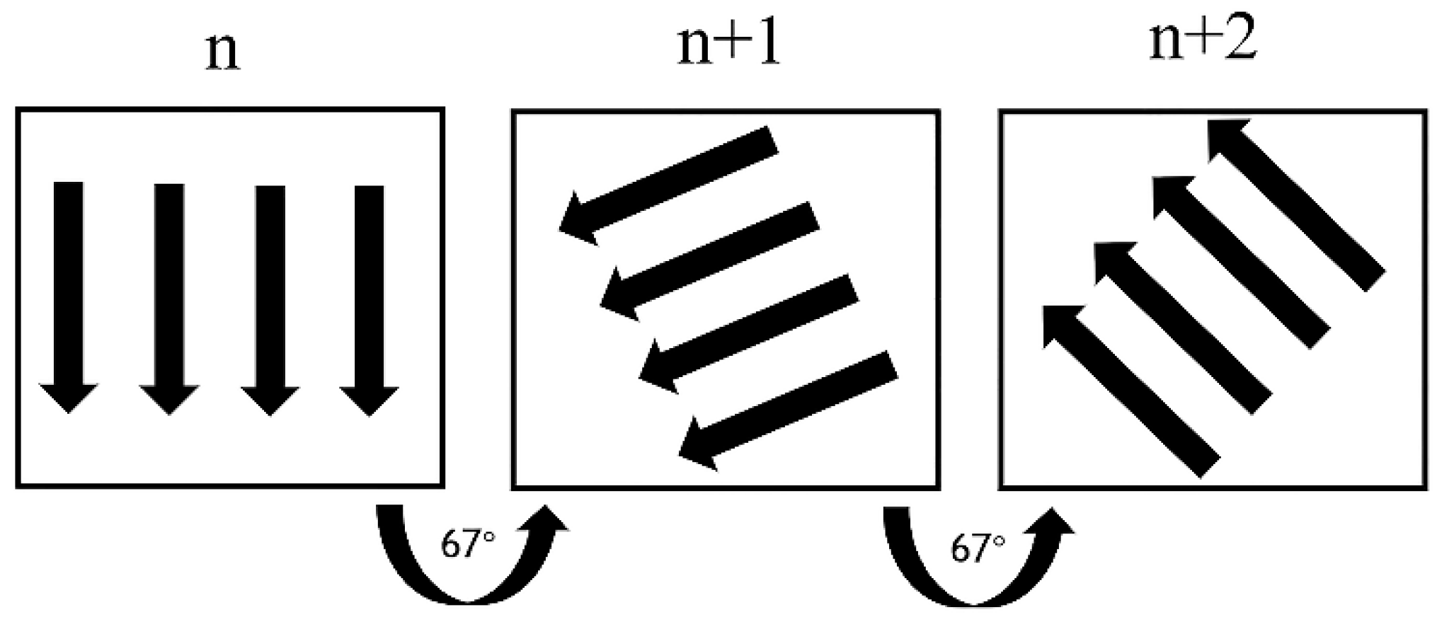
The experimental equipment is FS121M manufactured by Huashu Hi-Tech, China. The maximum laser power is 200 W, default is 180 W, double spot design diameter is 40–100 μm, default is 60 μm, effective forming area is 115 mm × 115 mm × 100 mm, maximum scanning speed is 1500 mm/s, default is 800 mm/s, layer thickness is 0.02–0.08 mm, default is 0.03 mm. After integrating the equipment, the structure of the support, and the research results of many scholars, it was decided to adopt the machining parameter scheme shown in Table 2, where the energy density is calculated by Equation (1), and in this study, the energy density was controlled within 40–120 J/mm3 to better explore the influence of the parameters on the performance. The scanning strategy was processed using a selected turn of 67° per layer [29], and the specific forming principle is shown in Figure 3:
ω = p vst
In the formula, P is the laser power (W), v is the laser scanning speed (mm/s), s is the laser hatching spacing (mm), and t is each laying powder thickness (mm), where t = 0.04 mm.

2.4. Analysis Methods

For the study of the 316L porous bone scaffolds, samples were sanded with 200–1200 grid SiC papers and polished to a mirror surface with 1µ diamond paste. Etching with aqua regia (HCl:HNO₃ = 3:1, ThermoFisher Scientific, Shanghai, China) and analysis of the grain morphology size, etc. were carried out using a Scanning Electron Microscope (SEM) (ZEISS SUPRA️ 55, Mainz, Germany). Phase characterization of porous bone scaffolds using X-ray diffraction (XRD), (Rigaku smartlab, Tokyo, Japan). XRD measurements were made with a step size of 0.05° and a step time of 1 s across 2θ positions between 20° and 100°. Residual stress testing of porous bone scaffolds using X-ray diffraction (Proto, Lasalle, Windsor, ON, Canada), The X-ray method has the advantages of the mature principle (the stress can be calculated by measuring the change in the lattice spacing), high precision, and nondestructive testing. It has a recognized authority in the field of residual stress nondestructive testing, which is helpful for effect verification before and after the process implementation. Hardness testing of porous bone scaffolds was carried out using hardness testing equipment (Union HV-1000, Guangdong, China) with a holding time of 15 s and a test load of 0.5N (Union HV-1000, China), with a holding time of 15 s, test load of 0.5 N. An electronic universal testing machine (WDW-100E, Shandong, China) was selected to perform compression experiments on porous bone scaffolds formed with different energy densities, and the loading speed was 0.1 mm/s for pressure loading.

2.5. Finite Element Simulations

In this study, the MSC Simufact Additive software was used to simulate the printing and forming process of porous bone scaffolds with an FCC structure, and to calculate the residual stress and deformation inside the scaffolds by means of an intrinsic strain model. In order to better understand the temperature and stress changes in the melt pool during processing, the temperature and stress fields in the melt pool were calculated using MSC Simufact Welding software. In the pre-processing, the mesh size of the finite element model was 0.05 mm and the boundary and loading conditions were consistent with the actual experiments.

3. Results and Discussion

3.1. Phase Characterization of Bone Scaffolds

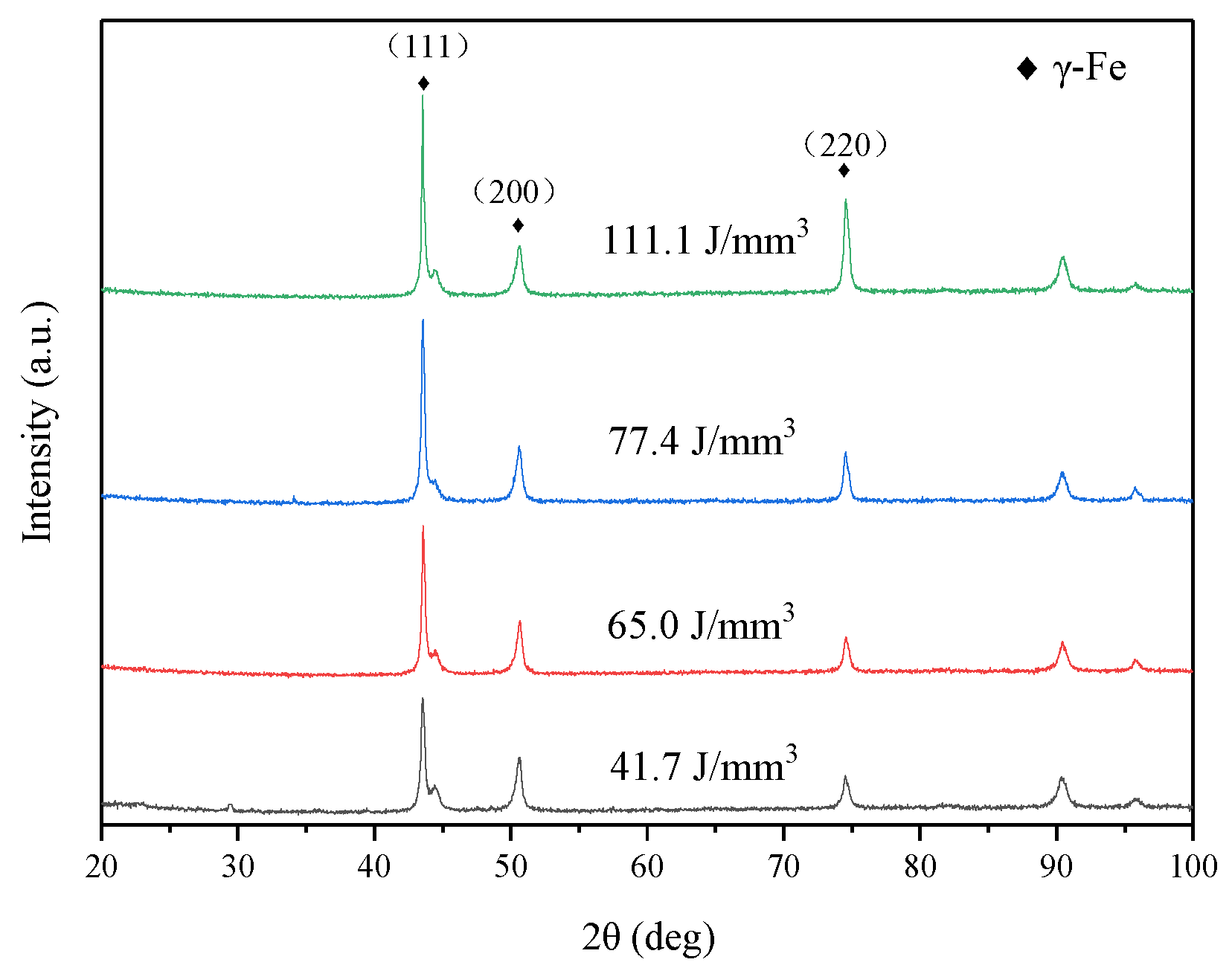
In this study, XRD tests were carried out on SLM-formed parts with energy densities of 41.7, 65.0, 77.4, and 111.1 J/mm3, as shown in Figure 4. For the porous scaffold XRD patterns in the range of 2θ (20°–100°), strong γ-Fe crystal faces (111), (200) and (220) diffraction peaks, and high contents of Ni and Cr in the formed part as seen in the XRD pattern can be clearly seen, where only a single austenitic phase was obtained. For the 2θ position, the intensity of the diffraction peaks and the half-peak width of the main peak data are shown in Table 3. A comparison with the 2θ position of the standard γ-Fe phase reveals a slight shift in the 2θ position of the porous scaffold machined and shaped using SLM, presumably arising from the thermal stress introduced by SLM itself. It is evident from Table 3 that the width of the diffraction peak of the γ-Fe phase significantly decreases when the energy density increases from 41.7 to 111.1 J/mm3, but the intensity increases significantly.
In addition, we can also use the XRD results to make a general prediction and comparison of the grain size of the porous bone scaffolds. The average crystallite size of the the bone scaffolds could be estimated based on the following Scherrer equation:
D C = 0.9 λ B cos θ
where B is the full width at half maximum of the XRD peak, θ is the diffraction angle, λ is the wavelength of the X-ray, and Dc is the grain size. From the formula, we can clearly see the relationship between the grains and energy densities, peak width, and X-ray wavelength. Combined with the test results of this study, we can boldly speculate that with an increase in the peak width, the grain size inside the porous bone scaffold should show a small trend. Through the XRD test, we found that the peak width is largely affected by the energy density, showing an inverse relationship with the energy density. Therefore, we can infer that with the increase in the energy density, the grain size inside the porous bone scaffolds should be gradually reduced.
The SLM process is a complex thermal processing process in which many factors affecting the internal grain structure and properties are incorporated into it. We cannot generalize about the internal grain structure and draw conclusions based on a simple test and mathematical model, which is obviously not rigorous. However, the appearance of Equation (2) does provide a certain reference for predicting the internal grain structure of the scaffolds.

3.2. Microstructure of Bone Scaffolds

The mechanical properties of bone scaffolds are mainly dependent on the microstructure of the material, and the thermal history during SLM processing plays a decisive role in the microstructure to a large extent. Localized high-energy irradiation in the powder bed tends to lead to large temperature gradients and high cooling rates, resulting in strong internal stress, affecting the grain growth and orientation. Defects in the microstructure are inherent to this process, and the reduction of the generation of defects and optimization of the mechanical properties are the focus of this study.
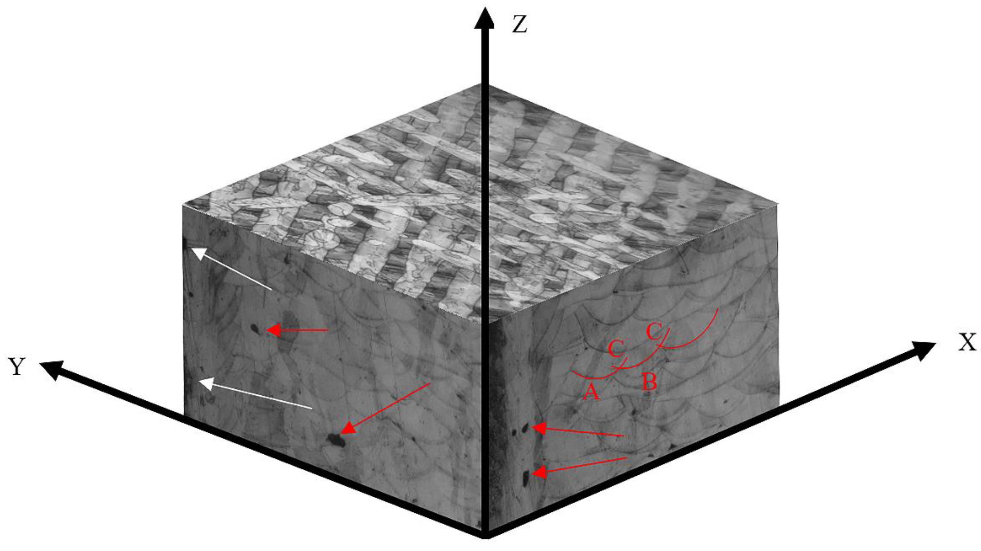
The optical image of the three-dimensional organization of the SLM-formed scaffold is shown in Figure 5, from which it is evident that in the XY plane, there is a melt pool map of the laser processing strategy. The melt pool is similar to many aligned weld channels from the top, and after etching, the boundaries become obvious and show a clear difference in the laser scanning direction between the new and old layers. In the XZ and YZ planes, there is a fish scale pattern in the melt pool structures produced by the laser process. These structures are roughly made up of three parts: melt pool A and B and remelt part C. In the experiments, it was found that the defects in the scaffolds formed at different energy densities varied, but most of them were dominated by regular round holes (shown by the red arrows), and there were also a few cracks, and a few cracks and irregular holes were also found near the edge of the melt pool (shown by the white arrows).
Figure 6 shows the internal grain structure of the melt pool for scaffolds formed at different energy densities . It is clear from Figure 6 that various crystal morphologies exist in different areas of the melt pool, mainly consisting of columnar and hexagonal equiaxed grains. The red dashed line shows the melt cell boundary, near which elongated hexagonal grains or columnar grains are predominant. The columnar grains are generally around 0.3–0.5 μm in diameter and a few tens of micrometers in length while the equiaxed grains are approximately 300–600 nm in size.
It is of interest to note that the columnar crystal organization near the boundary is not perfectly perpendicular to the tangent of the boundary—normally, the direction of maximum heat flow is generally normal to the fusion line—whereas in Figure 6, we see that there is a certain angular difference θ (shown by the white arrows) and we can see a significant difference in the size of θ as the processing parameters are changed. As shown in Table 4, as the energy density increases, the grain growth direction significantly changes, showing a tendency for the energy density to increase and the tangent angle to the melt pool to decrease. Especially, when the energy density is greater than 44.6 J/mm3, the offset angle changes most obviously. This provides a new entry point for the study of internal stress in the melt pool. The rate of solidification of the melt pool is determined by the temperature field, and the heat and flow within the melt pool define the shape of the melt pool, resulting in different internal stresses in the melt pool, which also determines the different grain growth directions. The angular difference may be due to the grain growth direction not only being influenced by the direction of the heat flow but possibly also by the preferred growth direction related to the grain structure, the tensile stresses at the edge of the melt pool, and the compressive stress at the center of the melt pool, which also provides internal energy for grain growth and elongation. In addition, the comparison reveals a high number of defects in the scaffolds formed using high-energy-density (≥100.0 J/mm3) processing, mainly in the form of irregular voids and cracks (shown by red arrows).
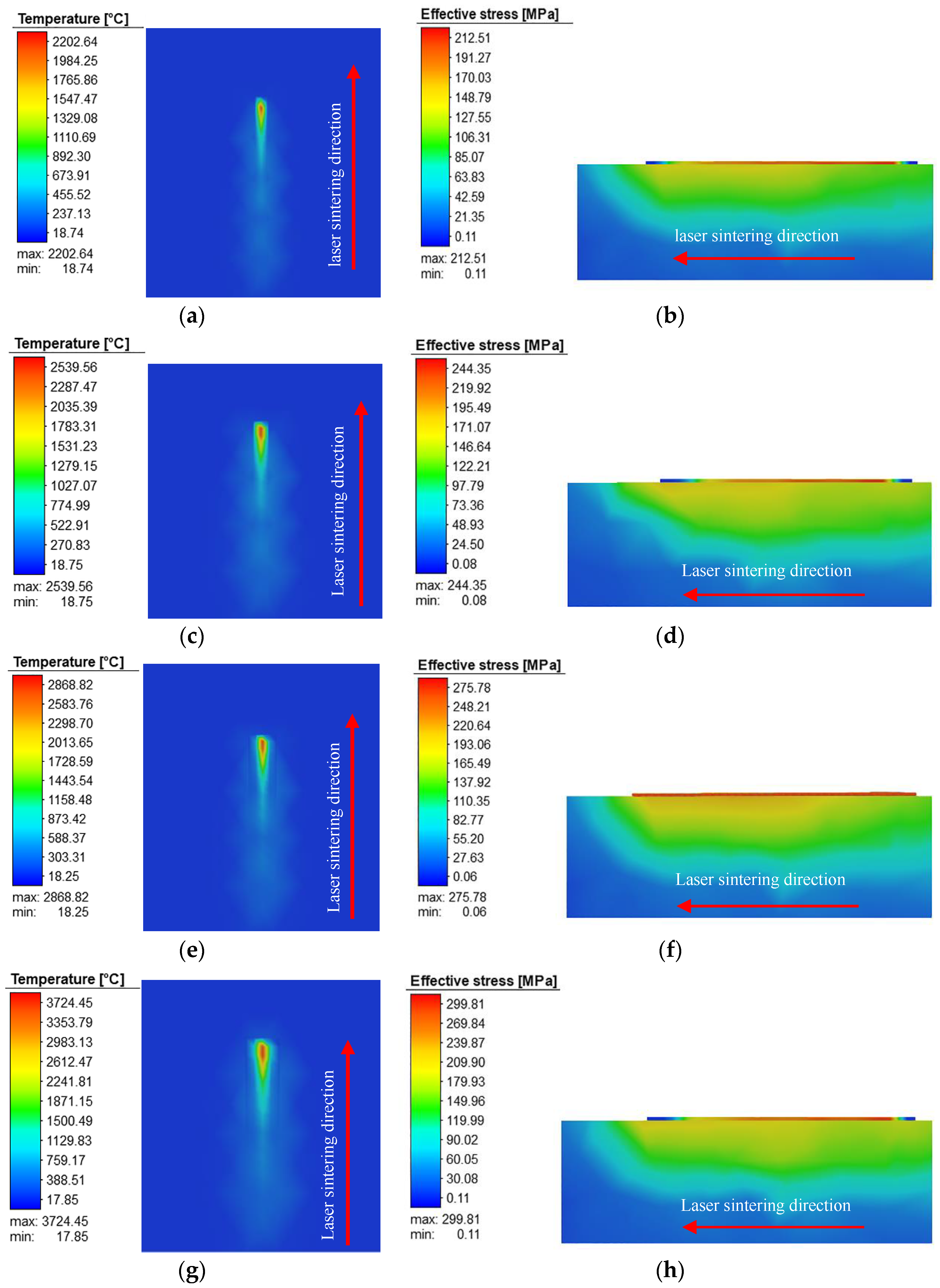
In order to better investigate the effect of energy densities on the processed melt pool, FEA was carried out on the temperature and stress fields of the melt pool in this study and the results are shown in Figure 7.
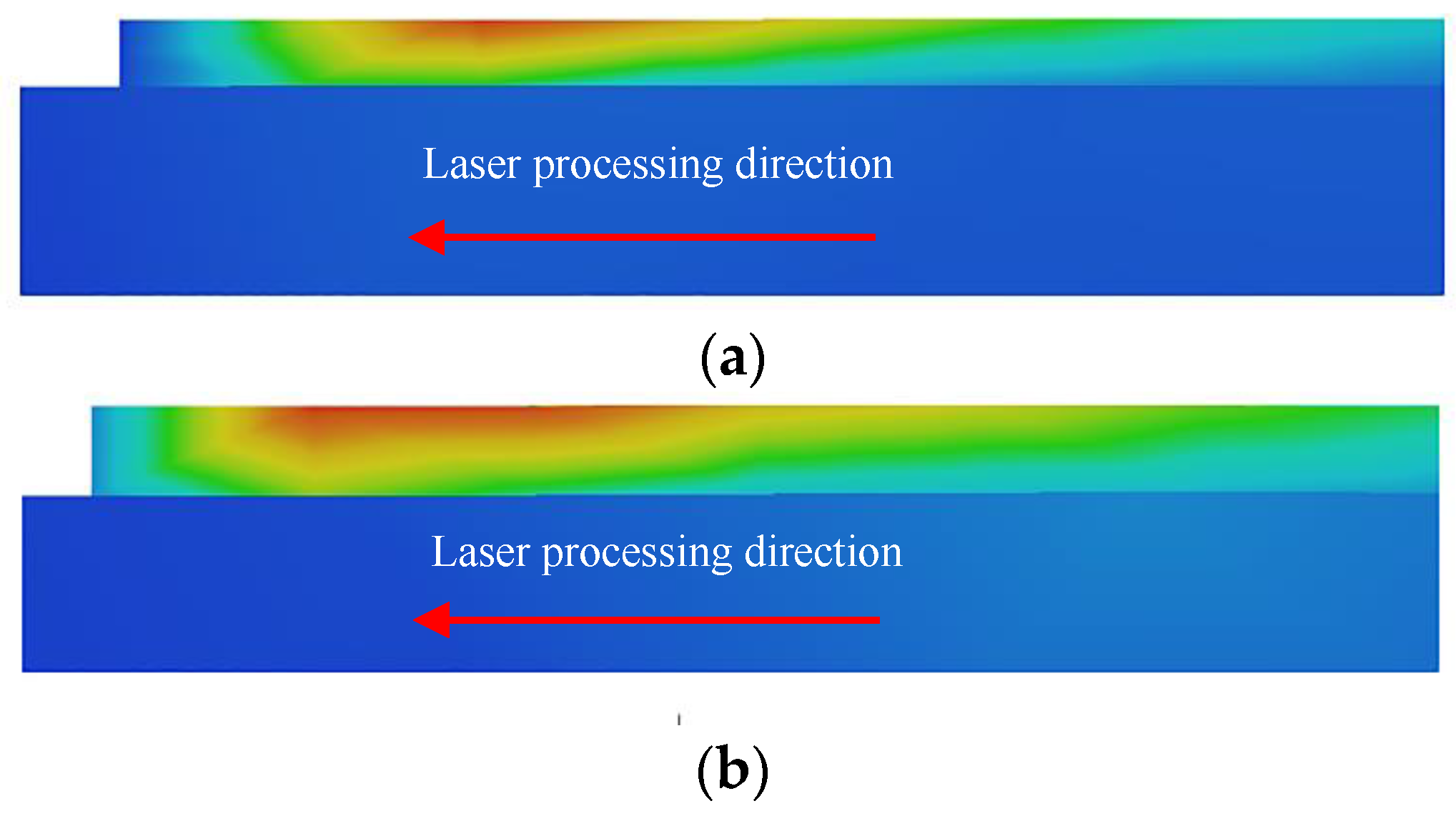
From the temperature field (a), (c), (e), and (g) plots in Figure 7, it is seen that the laser shows a predominantly comet-like path during processing, with a significantly higher temperature gradient in front of the heat source than at the tail. The most important factor influencing the difference in the melt pool morphology and temperature is the absorption ratio of the laser. Mahyar et al. [18] demonstrated that the absorption ratio of the laser is an important parameter to consider when studying the melt pool and related phenomena. Figure 7 shows the simulated analysis of the SLM process for layer 1. As seen in the figure, most of the heat generated by the laser beam is absorbed by the substrate, and as the energy density rises, the temperature within the melt pool gradually rises and the area of the generated thermal radiation increases. Combined with the cutaway view of the melt pool in Figure 8, it can be seen that the melt depth of the melt pool changes as the energy density increases from 41.7 to 111.1 J/mm3. For the difference in the melt pool depth, it is believed that the reason for this is that at higher temperatures, the molten state of the metal solution increases, and the pores between the surrounding unmelted powder cause the solution to flow unconstrained, so it tends to produce a melt pool surface with uneven heights, and when the laser beam is irradiated, the multiple reflections of the laser beam towards the end of the melt pool will further cause the depth of the melt pool to increase further, thus increasing the depth, as shown in Figure 8. A deeper melt pool allows for better bonding of the subsequent layers, but it can also lead to the introduction of a large amount of thermal stress, which causes corresponding internal stress in the solidified layer and the substrate during cooling, thus increasing residual stress.
SLM processing is usually a long process, and the repeated exposure to high energy densities causes the solidified layer to be reheated. Moreover, the greater the depth of radiation from the heat source, the more pronounced the repeated heating, which undoubtedly provides the conditions for more defects to arise, and potentially changes the morphology and structural distribution of the grains in the melt pool. As can be seen in the Figure 7 stress fields (b), (d), (f), and (h), the change in the energy density has a huge impact not only on the temperature field but also on the matrix and solidification layer, which shows a positive relationship between the stress values and energy density. It is also interesting to note from the diagram that most of the stresses after machining are concentrated in the substrate. The reason for this is that the substrate was at room temperature at the beginning, and the high-energy laser beam and the large temperature gradient cause thermal expansion of the substrate, resulting in thermal stress and induced deformation. In the end, large residual stresses were generated internally. The cladding layer of a porous scaffold is fused directly to the substrate; therefore, the magnitude and distribution of residual stress within the substrate will also have an influence on the magnitude and distribution of internal stress in the scaffold due to force interactions, which in turn will also have an influence on the shape of the melt pool and the orientation of the internal grain tissue growth.
Figure 9 shows the primary dendrite spacing inside the melt pool for the nine process parameters. The primary dendrite spacing can be calculated from Equation (3), where M is the magnification, N is the number in the selected area, and A is the area of the selected area. As can be seen from the graph, the grain size changes with the SLM processing conditions. When the energy density is 83.3 J/mm3, it reaches the minimum, and when the energy density is 65.0 and 67.7 J/mm3, the grain size suddenly increases. It is speculated that this is due to improper processing parameters, which affect the cooling and solidification in the molten pool. In combination with the stress field analysis in Figure 7d, the stress field range under this process parameter is significantly larger than that under other process parameters, thus causing changes in the grain structure during crystallization:
δ = 1 M ( A N ) 1 2
In SLM processing, if the melt pool is being studied, it is necessary to mention the problem of subcooling. The difference in subcooling during the solidification of the melt pool can easily lead to changes in the shape, size, and arrangement of the grains inside the melt pool, and the kinetic subcooling in SLM processing is usually defined by Equations (4) and (5), where λ is the interfacial kinetic coefficient, VS is the scanning velocity, V0 is the speed of sound (m/s), KB is the Boltzmann constant, and TL is the liquid phase line temperature (k). According to the relevant solidification theory of Fischer et al. [30], a larger subcooling degree ΔTk helps to increase the nucleation rate:
Δ T k = V s λ
λ = Δ H f V 0 k B T L 2
In the experimental results of this study, if we refer to Equation (4) to explore the factors affecting the development of dendrites, it was found that when a smaller energy density was used, e.g., 44.6 J/mm3, a scanning speed of 700 mm/s was chosen and the largest grain size was produced; when an energy density of 41.76 J/mm3 was used, the scanning speed was 500 mm/s and the smallest grain size was produced. This is completely contrary to the conclusion of Wang [31] and others that ΔTk can be significantly enhanced with increasing scan speeds, thereby refining the microstructure of SLM-machined parts and consequently reducing the primary dendrite spacing. In this study, the biggest difference between the above two energy densities in terms of processing parameters is the difference between the scanning speed and the hatching spacing, and the hatching spacing is not specifically cited in the supercooling degree.
In SLM processing, the processing principle is the use of the laser beam to transfer heat to the heat-affected zone; then, the power of the laser beam and the radiation area will also affect the development of cellular dendrites in the heat-affected zone. If we simply use Equation (4) to explore the development law of cellular dendrites in SLM processing, this is not rigorous, so we refer to the results of Fischer et al. [23] and analyze the change in the maximum temperature rise in the melt pool using Equation (6), where A is the laser absorption rate, k is the thermal conductivity, kth is the thermal diffusivity, and τp is the laser irradiation duration:
Δ T max = 2 A ω k k t h T p π
From Equation (6), we see that the temperature field within the melt pool is influenced by the thermal conductivity, thermal diffusion, laser absorption, etc. Combined with the results of the present experimental analysis, it is found that low scanning speeds usually result in higher energy densities, which leads to an increase in the working temperature within the melt pool, with a large amount of heat tending to collect near the larger dendrites and mainly dissipate through the melt pool boundary, which also provides energy for cellular dendrites to grow. It was found that the use of a lower energy density or laser power is small, and it is appropriate to reduce the scanning speed, which can enhance the internal temperature of the melt pool, thus controlling the melt pool tissue grain size. When the laser power is 160 W, it was found that with the speed of the promotion, the grain size gradually became smaller. We propose that in SLM processing, when large laser power processing is used, a faster scanning speed should be used and when small laser power processing is used, a slower scanning speed should be chosen to ensure that in the melt pool, heat transfer and solidification and the release of sufficient heat occurs, thus promoting the new melt pool boundary being near the solidified layer of grain recrystallization and growth to obtain fine grain refinement.

3.3. Residual Stress in Bone Scaffolds

Residual stress is stress that remains within the material when it has reached equilibrium with its surroundings. Residual stress varies with the size of the part and in most cases is not required as it causes deformation of the desired shape. Every production process introduces a certain amount of residual stress and the number of residual stresses introduced varies considerably from one production process to another. It is well known that in SLM processing, large and steep thermal gradients are created in the structure itself due to rapid heating and slower heat transfer. Although additive manufacturing techniques are capable of producing metal parts with complex geometries, their suitability for critical applications is often adversely affected by residual stress control [17,32].
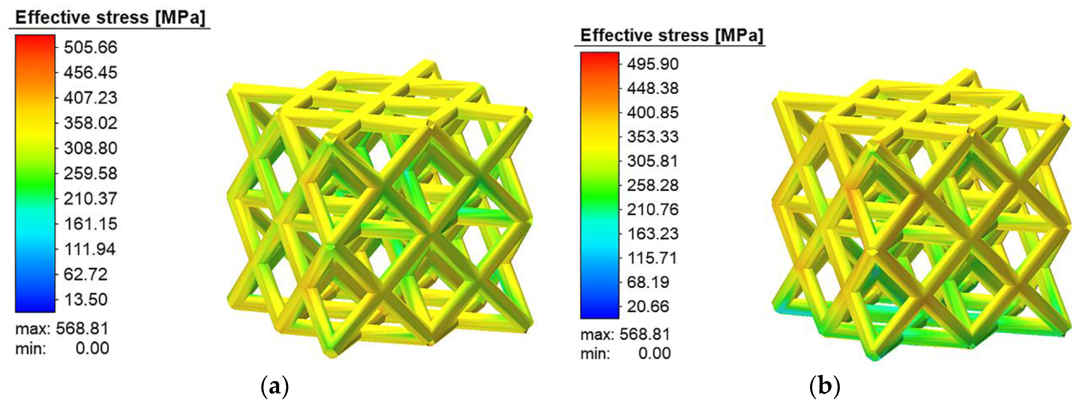
Figure 10 shows the magnitude and distribution of residual stress after the formation of the porous bone scaffolds of the FCC structure at ω = 111.1 J/mm3 calculated by finite elements.
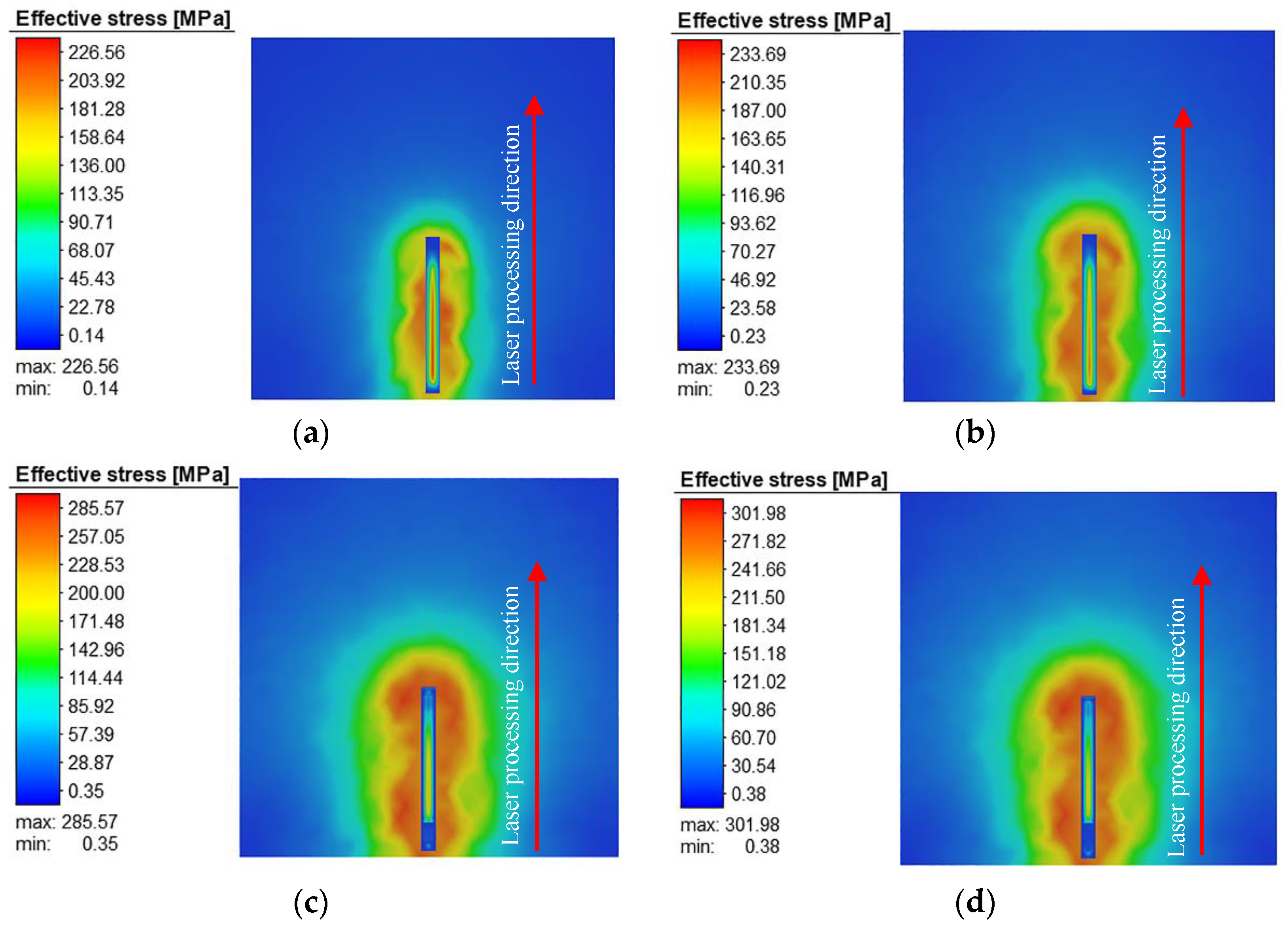
Figure 10 shows the scaffold before and after the removal of the substrate after formation. It can be clearly found that after the removal of the substrate, the residual stress under the bone scaffold was significantly reduced, and there was also a slight reduction in the middle and top of the scaffold. The reason for this may be that before the removal of the substrate, the stress inside the scaffold was equal to the yield strength of the upper layer of the substrate, and when the scaffold was removed from the substrate, the stress state inside the scaffold changed drastically, and the stress generated in the scaffold was reduced due to the relaxation effect. Additionally, it was found through FEA calculations that the residual stress inside the scaffold is characterized by dynamic changes between layers. The reason for this phenomenon may be that during the SLM formation process, there are differences in the shape area between layers, resulting in the cooling shrinkage of the melt pool being limited by the solidified cladding layer, which creates an elastic compression strain. Figure 11 shows the stress variation in the substrate and laser scan path as different layers are constructed. It can be visualized that each additional layer introduces a different degree of residual stress in the substrate and the stress distribution generated in the solidified layer below gradually expands. The large amount of residual stress that accumulates in the substrate causes plastic deformation of the substrate, which is particularly pronounced in the area where the substrate is fused to the scaffold fixation, and thus tends to have an effect on the internal stress in the new layer.
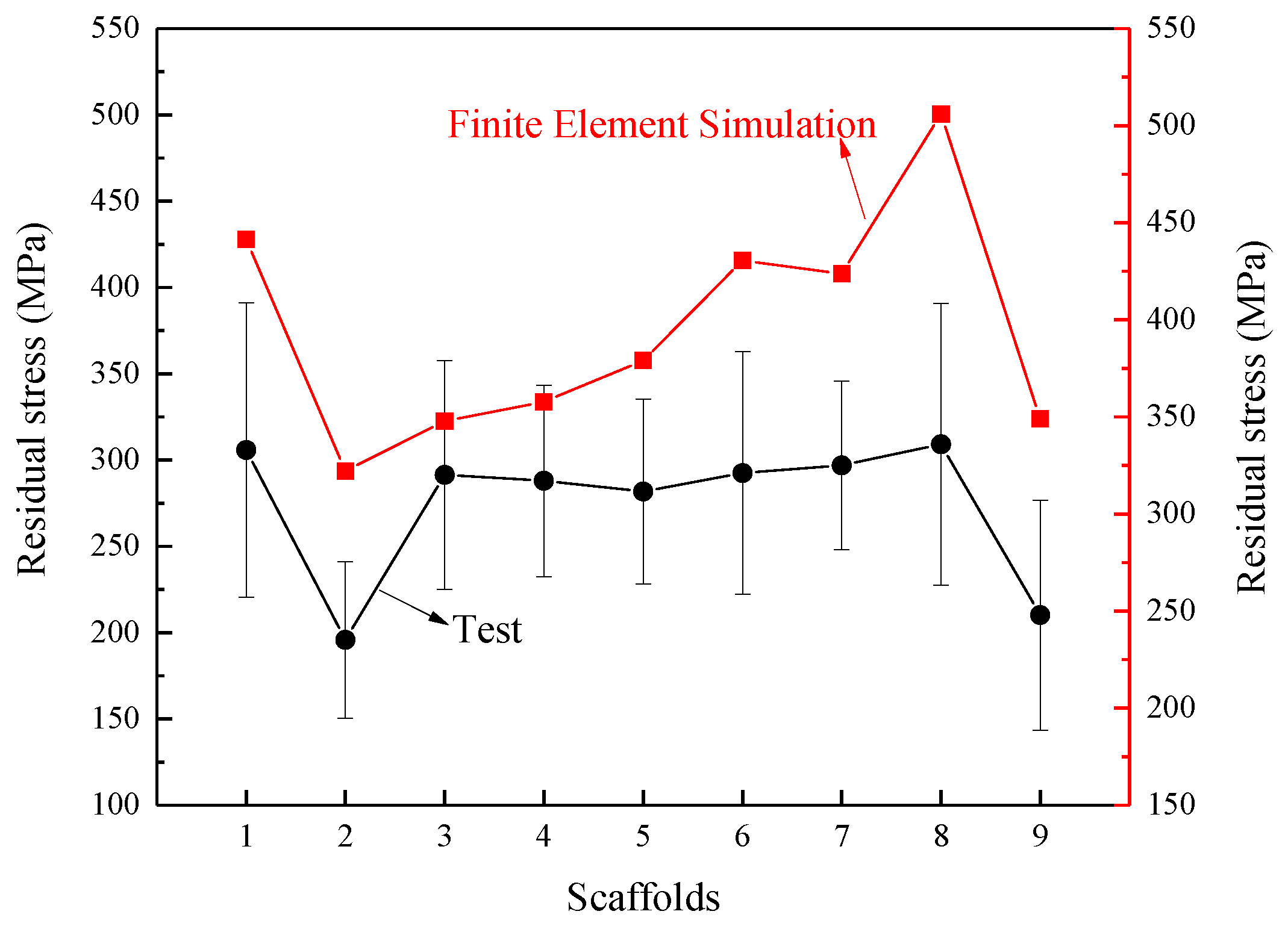
The residual stress in the scaffolds was tested using the XRD non-destructive method, and the results of the tests and finite element simulations are shown in Figure 12. As can be seen from the graph, among the nine machining parameters, the use of an energy density of 41.7 J/mm3 for the manufacture of FCC structural supports has a small residual stress, but when 111.1 J/mm3 was used, the residual stress in the bone scaffold increased significantly. The results obtained from the finite element simulations and the actual experiments are in general agreement, which also proves that the use of finite element means can produce some pre-prediction of the residual stress generated in the actual manufacturing and thus improve the situation.

3.4. Residual Deformation of the Bone Scaffold

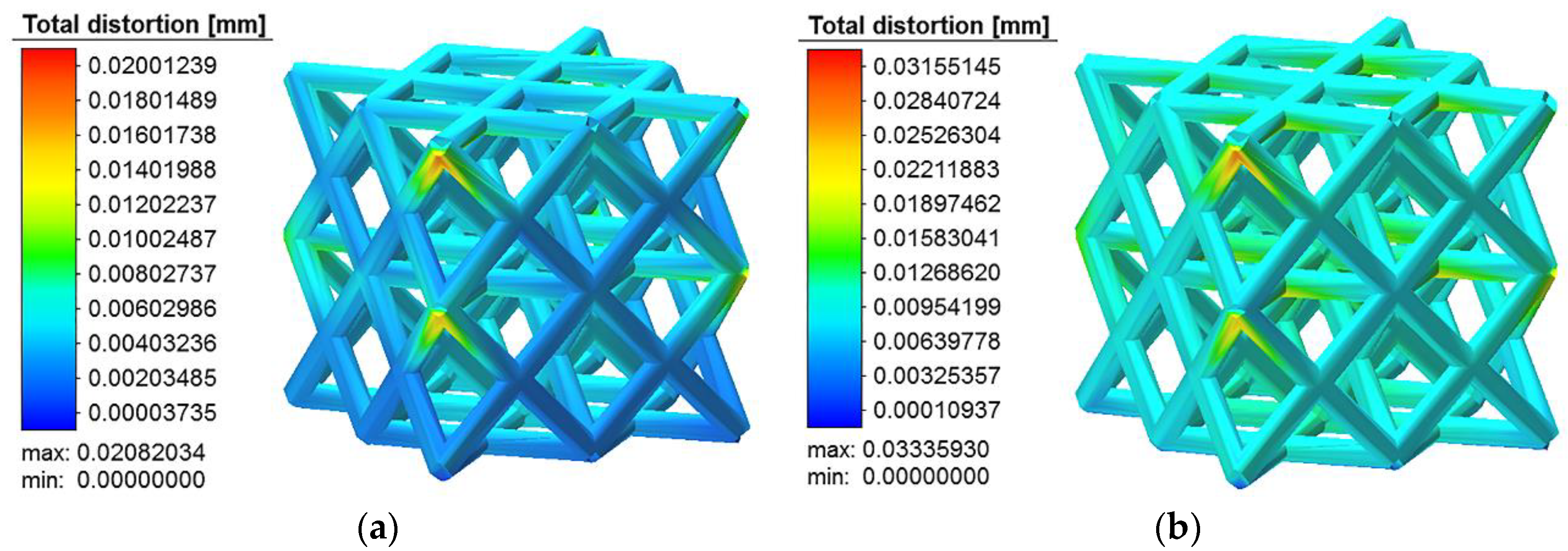
Two main factors contribute to the deformation of the bone scaffolds: one is the deformation due to the stress strain during the SLM construction process, and the other is the deformation caused by phenomena such as powder adhesion and the spherification phenomenon during the machining process. Figure 13 shows the deformation of the porous bone scaffolds at different energy densities. The larger deformation is found at the unit-column joints and the lower surface of the unit-column of the FCC structure while the other locations are deformed but to a lesser extent. The effect of the energy density on the amount of deformation shown in Figure 14a shows that there are significant differences in the effect of the energy density on the amount of residual deformation, with a relatively small amount of deformation (0.63%) obtained with an energy density of 41.7 J/mm3. The deformation in the manufacture of porous bone scaffolds is inevitable and mainly occurs because, when forming porous structures, the SLM system’s support function is abandoned, resulting in the unit column with a certain upward inclination to the horizontal plane being in a semi-supported state in the molten state, with the unmolten powder providing support. This also results in direct contact between the melt pool and a large amount of powder during the first layer or a small number of layers, which collects in the melt pool and adheres to the surface during the solidification of the melt pool. In addition, it is explained from the processing characteristics of SLM that when a solidified layer is formed and a new layer is formed, the solidified layer acts as a support. At this time, the semi-molten or unmelted powder existing on the upper surface of the old solidified layer is melted by secondary processing with the irradiation of the laser beam while the bonded powder on the lower surface is not fully irradiated by the laser because the powder bed fusion is processed layer by layer. Although, the melting point of the powder may be reached at high temperatures and new powder may be re-bonded after solidification. It can be clearly seen from Figure 14b that the powder bonded on the upper surface of the FCC unit column is compact and the surface is gentle while the bonded powder on the lower surface is loose and messy, and there is a risk of falling off under stress.
The long-term functional use of porous bone scaffolds as human implants does not allow for a situation where the surface of the scaffold is stripped of unmelted powder during use, so the selection of suitable processing parameters to reduce the amount of distortion and defects in the adhering powder must be considered and optimized. Table 5 shows the comparison between the software design dimensions and the SLM formation dimensions at different energy densities. It can be seen that due to the characteristics of powder bed fusion processing, the dimensions of the FCC structural unit columns significantly change and there are differences between the design values and the experimental values. The main objective of this study was to compare and analyze different energy densities to select the optimum processing parameters for the formation of porous bone scaffolds with an excellent performance in all aspects.

3.5. Mechanical Properties of Bone Scaffolds

3.5.1. Microhardness

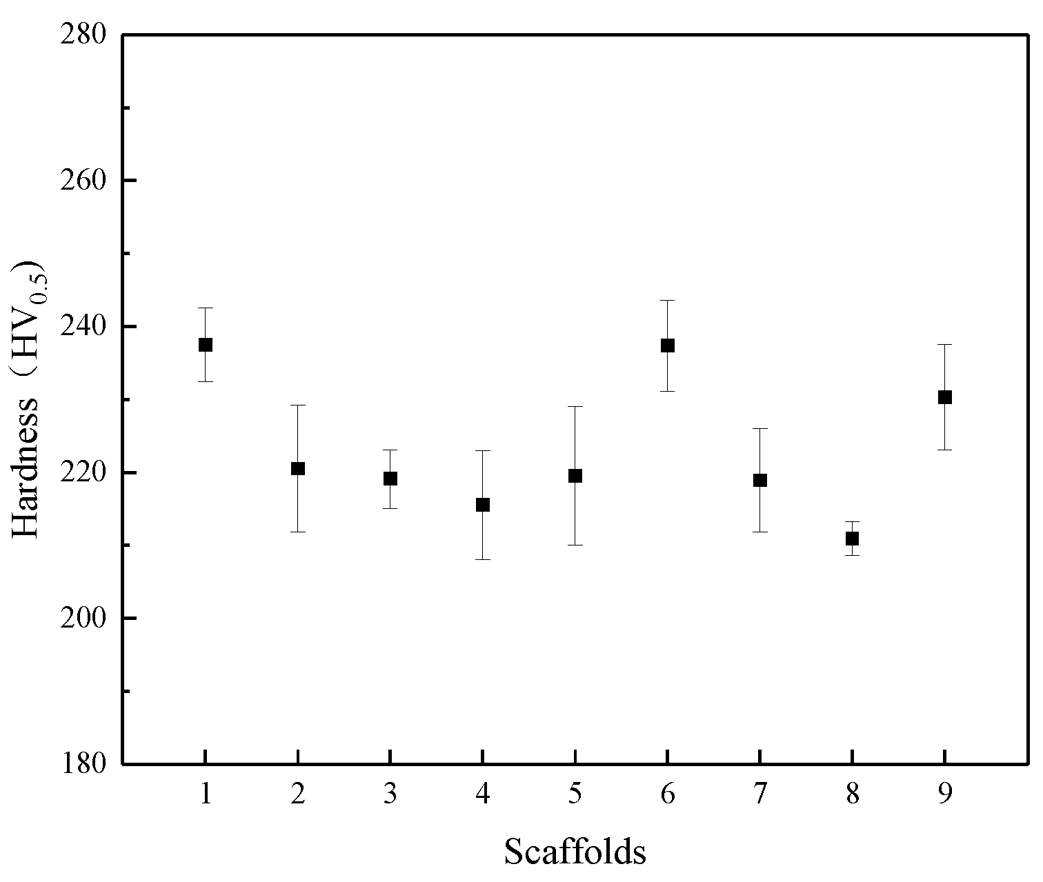
Figure 15 shows the microhardness of the SLM-machined scaffolds, from which it can be seen that there are significant differences in the hardness caused by the different machining solutions, where the lowest average microhardness of 210.9 HV0.5 was obtained at an energy density of 111.1 J/mm3 and the highest average microhardness of 237.34 HV0.5 was obtained at an energy density of 77.4 J/mm3. The main reasons for this significant difference in microhardness are (1) that the different processing parameters lead to different densities of the parts, which results in significant changes in the microhardness of the scaffolds; and (2) the different processing parameters lead to different defects in the parts, such as significant periodization, a large number of cracks and holes, and the presence of molten powder inside the melt pool during the formation of the scaffolds, etc., which all have an impact on the microhardness of the scaffolds.
In conjunction with the microstructure characterization of the scaffold shown in Figure 6, it can be seen that at higher energy densities (111.1 J/mm3), some large pores are found between the adjacent melt pool boundary trajectories, which, on the one hand, affect the densities of the scaffold and, on the other hand, can trap part of the unmelted powder within the pores. When a lower energy density was used (41.7 J/mm3), no defects were evident on the surface of the bone scaffold. Although the energy density was lower, the diameter of the bone scaffold unit was also smaller, the laser radiation zone was smaller, and the liquid flow in the melt pool was reduced, making it less likely that the powder would adhere.

3.5.2. Compression Properties

The microstructure determines the mechanical properties of SLM parts, and different processing parameters are the main influencing factors of the different microstructures. Figure 16 shows the stress–strain curves of the FCC-structured porous bone scaffold formed at different energy densities for the compression experiments. The difference between the stress–strain curves for high/low energy densities was found to be more pronounced, with the porous scaffolds formed at high energy densities showing a poorer compression performance, presumably due to the defects mentioned in the previous section, with greater unmelted powder adherence to the surface of the unit causing a reduction in the compressive performance. As can be seen from the figure, all the scaffolds exhibit similar stress–strain trends, which can be broadly divided into three stages, and Table 6 corresponds to the three stages in Figure 16, respectively. The deformation in the initial stage (I) is mainly characterized by the outward expansion of the surrounding area, and the porous scaffold is in the elastoplastic deformation stage, which mainly relies on the tensile deformation of the bone scaffold unit body. As the load force increases, in the intermediate stage (II), the porous units are gradually deformed and distorted, the pore size of the porous structure is significantly reduced, a significant fracture can be seen in the central part, and the whole scaffold is plastically deformed, resulting in a relative reduction in the compressive performance. As the load force continues to increase, the porous structure continues to deform and the units gradually come into close contact with each other, leading to an increase in the compressive performance and a later stage (III). However, another factor that is not negligible in improving the compressive performance in this stage is the large amount of agglomerated powder adhering to the surface of the scaffold, where the high density of the aggregates can also prevent the compressive deformation of the pores in the porous scaffold.

3.5.3. Modulus of Elasticity of the Bone Scaffolds

One of the issues that cannot be ignored when implanting a metal porous bone scaffold is the modulus of elasticity between the implant and the human bone. Scaffolds should be designed to meet the mechanical properties of the natural bone at the implantation site, i.e., the modulus of elasticity, which ranges between 17 and 20 GPa for cortical bone and 3.2 and 7.8 GPa for cancellous bone. Scaffolds designed with too high or too low a modulus of elasticity are prone to stress shielding and can lead to osteoporosis in the adjacent bone after implantation. Table 7 shows the data relating to the modulus of elasticity of bone scaffolds formed using nine energy densities.
Equation (7) of the Gibson–Ashby [33] model is a formula used to calculate the modulus of elasticity of porous structures, developed for porous structures:
E * E S = C ( ρ * ρ S ) m
where E* is the elastic modulus of the porous bone scaffold, Es is its solid elastic modulus, Es = 210 GPa, ρ* is the density of the porous bone scaffold, ρs is its solid density, ρs = 7.98 g/cm3, and C and m are the open structure geometric constants of C = 1 and m = 2, respectively.

4. Conclusions and Prospects

In this experiment, a combination of finite element simulation and experiments were used to investigate the mechanism of the impact of SLM on porous scaffolds with different energy densities in the formation of FCC structures from different perspectives. The main conclusions are as follows:
  • In SLM processing, the difference in the laser energy density leads to the appearance of grain structures with different shapes and different forming angles in the melt pool. With the increase in the energy density, the direction of grain formation in the molt pool shifts from 80° to 50°. At the same time, improper energy density processing is more likely to cause deformed grains at the edge of the molt pool, which leads to cracks and holes, and reduces the mechanical properties of the porous scaffolds.
  • Among the factors determining the energy density, the scanning speed of the laser and the laser power have the most significant effect on the grain size of the porous scaffolds. When the energy density increased from 41.7 to 111.1 J/mm3, the average primary dendrite spacing increased from 441 to 501 nm and this change led to a significant difference in the performance of the porous scaffolds.
  • For the mechanical properties of porous scaffolds, laser processing with high energy densities (≥100.0 J/mm3) tends to achieve a lower microhardness (214.92 HV0.5) while processing with lower energy densities (<100.0 J/mm3) can increase the average microhardness by a maximum of about 9.4% in comparison, up to 237.34 HV0.5. In terms of the compressive performance, the porous bone scaffolds constructed with high energy densities were approximately 10% to 17% less than the other construction energy densities.
  • The elastic modulus of the bone scaffolds was tested, and it was found that the porous bone scaffolds formed by SLM basically met the requirements for human bone implantation, but the high energy density (111.1 J/mm3) used to construct the porous bone scaffolds with an FCC structure could easily lead to a decrease in the formation accuracy of the scaffolds and make the performance of the scaffolds exceed the ideal expectations.
In this study, the mechanism of the effect of different energy densities on various aspects of the performance of FCC-structured porous bone scaffolds was obtained; however, for the practical clinical application of bone scaffolds, a series of post-treatments (e.g., stress-releasing treatment, etc.) are required to better enhance the performance of the scaffolds. Numerous studies [16,34,35] have shown that the use of direct aging and annealing treatments can significantly improve the performance of additively manufactured products, and therefore the future focus of this study is to improve the performance of scaffolds by means of heat treatment to enable better application of artificial bone scaffolds.

Author Contributions

Data curation, S.Z.; Formal analysis, S.Z.; Writing—Original draft preparation, S.Z.; Software, S.Z.; Conceptualization, S.X.; Methodology, S.X.; Review and Editing, S.X.; Funding acquisition, S.X.; Investigation, Y.P.; Methodology, Y.P.; Resources, Y.P.; Funding acquisition, J.L.; Resources, J.L.; Supervision, J.L.; Review and Editing, J.L.; Data curation, T.L.; Investigation, T.L.; Funding acquisition, T.L. All authors have read and agreed to the published version of the manuscript.

Funding

This study was supported by Natural Science Foundation of Shandong Province (ZR2021ME182).

Data Availability Statement

The data presented in this study are available on request from the corresponding author.

Conflicts of Interest

The authors declare no conflict of interest.

References

  1. Arjunan, A.; Demetriou, M.; Baroutaji, A.; Wang, C. Mechanical performance of highly permeable laser melted Ti6Al4V bone scaffolds. J. Mech. Behav. Biomed. Mater. 2020, 102, 103517. [Google Scholar] [CrossRef]
  2. Bai, L.; Gong, C.; Chen, X.; Zheng, J.; Xin, L.; Xiong, Y.; Wu, X.; Hu, M.; Li, K.; Sun, Y. Quasi-Static compressive responses and fatigue behaviour of Ti-6Al-4 V graded lattice structures fabricated by laser powder bed fusion. Mater. Des. 2021, 210, 110110. [Google Scholar] [CrossRef]
  3. Li, J.; Jansen, J.A.; Walboomers, X.F.; van den Beucken, J.J. Mechanical aspects of dental implants and osseointegration: A narrative review. J. Mech. Behav. Biomed. Mater. 2020, 103, 103574. [Google Scholar] [CrossRef] [PubMed]
  4. Coffigniez, M.; Gremillard, L.; Balvay, S.; Lachambre, J.; Adrien, J.; Boulnat, X. Direct-ink writing of strong and biocompatible titanium scaffolds with bimodal interconnected porosity. Addit. Manuf. 2021, 39, 101859. [Google Scholar] [CrossRef]
  5. Kumar, P.; Ramamurty, U. Microstructural optimization through heat treatment for enhancing the fracture toughness and fatigue crack growth resistance of selective laser melted Ti 6Al 4V alloy. Acta Mater. 2019, 169, 45–59. [Google Scholar] [CrossRef]
  6. Chao, Q.; Cruz, V.; Thomas, S.; Birbilis, N.; Collins, P.; Taylor, A.; Hodgson, P.D.; Fabijanic, D. On the enhanced corrosion resistance of a selective laser melted austenitic stainless steel. Scr. Mater. 2017, 141, 94–98. [Google Scholar] [CrossRef]
  7. Jiang, H.-Z.; Li, Z.-Y.; Feng, T.; Wu, P.-Y.; Chen, Q.-S.; Feng, Y.-L.; Chen, L.-F.; Hou, J.-Y.; Xu, H.-J. Effect of Process Parameters on Defects, Melt Pool Shape, Microstructure, and Tensile Behavior of 316L Stainless Steel Produced by Selective Laser Melting. Acta Met. Sin. Engl. Lett. 2020, 34, 495–510. [Google Scholar] [CrossRef]
  8. Oliveira, J.P.; LaLonde, A.D.; Ma, J. Processing parameters in laser powder bed fusion metal additive manufacturing. Mater. Des. 2020, 193, 108762. [Google Scholar] [CrossRef]
  9. Liverani, E.; Toschi, S.; Ceschini, L.; Fortunato, A. Effect of selective laser melting (SLM) process parameters on microstructure and mechanical properties of 316L austenitic stainless steel. J. Mater. Process. Technol. 2017, 249, 255–263. [Google Scholar] [CrossRef]
  10. Sing, S.L.; An, J.; Yeong, W.Y.; Wiria, F.E. Laser and electron-beam powder-bed additive manufacturing of metallic implants: A review on processes, materials and designs. J. Orthop. Res. 2015, 34, 369–385. [Google Scholar] [CrossRef]
  11. Davoodi, E.; Montazerian, H.; Mirhakimi, A.S.; Zhianmanesh, M.; Ibhadode, O.; Shahabad, S.I.; Esmaeilizadeh, R.; Sarikhani, E.; Toorandaz, S.; Sarabi, S.A.; et al. Additively manufactured metallic biomaterials. Bioact. Mater. 2022, 15, 214–249. [Google Scholar] [CrossRef] [PubMed]
  12. Deng, F.; Liu, L.; Li, Z.; Liu, J. 3D printed Ti6Al4V bone scaffolds with different pore structure effects on bone ingrowth. J. Biol. Eng. 2021, 15, 4–16. [Google Scholar] [CrossRef] [PubMed]
  13. Cosma, C.; Kessler, J.; Gebhardt, A.; Campbell, I.; Balc, N. Improving the Mechanical Strength of Dental Applications and Lattice Structures SLM Processed. Materials 2020, 13, 905. [Google Scholar] [CrossRef] [PubMed] [Green Version]
  14. Capek, J.; Machova, M.; Fousova, M.; Kubásek, J.; Vojtěch, D.; Fojt, J.; Jablonská, E.; Lipov, J.; Ruml, T. Highly porous, low elastic modulus 316L stainless steel scaffold prepared by selective laser melting. Mater. Sci. Eng. C 2016, 69, 631–639. [Google Scholar] [CrossRef] [PubMed]
  15. Zhu, Y.; Zou, J.; Yang, H.-Y. Wear performance of metal parts fabricated by selective laser melting: A literature review. J. Zhejiang Univ. A 2018, 19, 95–110. [Google Scholar] [CrossRef]
  16. Yadollahi, A.; Shamsaei, N.; Thompson, S.M.; Seely, D.W. Effects of process time interval and heat treatment on the mechanical and microstructural properties of direct laser deposited 316L stainless steel. Mater. Sci. Eng. A 2015, 644, 171–183. [Google Scholar] [CrossRef]
  17. Wang, Z.; Denlinger, E.; Michaleris, P.; Stoica, A.D.; Ma, D.; Beese, A.M. Residual stress mapping in Inconel 625 fabricated through additive manufacturing: Method for neutron diffraction measurements to validate thermomechanical model predictions. Mater. Des. 2017, 113, 169–177. [Google Scholar] [CrossRef] [Green Version]
  18. Khorasani, M.; Ghasemi, A.; Leary, M.; Sharabian, E.; Cordova, L.; Gibson, I.; Downing, D.; Bateman, S.; Brandt, M.; Rolfe, B. The effect of absorption ratio on meltpool features in laser-based powder bed fusion of IN718. Opt. Laser Technol. 2022, 153, 108263. [Google Scholar] [CrossRef]
  19. Mercelis, P.; Kruth, J. Residual stresses in selective laser sintering and selective laser melting. Rapid Prototyp. J. 2006, 12, 254–265. [Google Scholar] [CrossRef]
  20. Song, B.; Dong, S.; Deng, S.; Liao, H.; Coddet, C. Microstructure and tensile properties of iron parts fabricated by selective laser melting. Opt. Laser Technol. 2014, 56, 451–460. [Google Scholar] [CrossRef]
  21. Abe, F.; Santos, E.C.; Kitamura, Y.; Osakada, K.; Shiomi, M. Influence of forming conditions on the titanium model in rapid prototyping with the selective laser melting process. Proc. Inst. Mech. Eng. Part C J. Mech. Eng. Sci. 2003, 217, 119–126. [Google Scholar] [CrossRef]
  22. Zhou, Y.; Abbara, E.M.; Jiang, D.; Azizi, A.; Poliks, M.D.; Ning, F. High-cycle fatigue properties of curved-surface AlSi10Mg parts fabricated by powder bed fusion additive manufacturing. Rapid Prototyp. J. 2022, 28, 1346–1360. [Google Scholar] [CrossRef]
  23. Xu, S.; Zhang, S.; Ren, G.; Pan, Y.; Li, J. Optimization of Structural and Processing Parameters for Selective Laser Melting of Porous 316L Bone Scaffolds. Materials 2022, 15, 5896. [Google Scholar] [CrossRef] [PubMed]
  24. Giganto, S.; Martínez-Pellitero, S.; Cuesta, E.; Zapico, P.; Barreiro, J. Proposal of design rules for improving the accuracy of selective laser melting (SLM) manufacturing using benchmarks parts. Rapid Prototyp. J. 2022, 28, 1129–1143. [Google Scholar] [CrossRef]
  25. Moniruzzaman, M.; O'Neal, C.; Bhuiyan, A.; Egan, P.F. Design and Mechanical Testing of 3D Printed Hierarchical Lattices Using Biocompatible Stereolithography. Designs 2020, 4, 22. [Google Scholar] [CrossRef]
  26. Poltue, T.; Karuna, C.; Khrueaduangkham, S.; Seehanam, S.; Promoppatum, P. Design exploration of 3D-printed triply periodic minimal surface scaffolds for bone implants. Int. J. Mech. Sci. 2021, 211, 106762. [Google Scholar] [CrossRef]
  27. Tan, X.; Tan, Y.; Chow, C.; Tor, S.; Yeong, W. Metallic powder-bed based 3D printing of cellular scaffolds for orthopaedic implants: A state-of-the-art review on manufacturing, topological design, mechanical properties and biocompatibility. Mater. Sci. Eng. C 2017, 76, 1328–1343. [Google Scholar] [CrossRef]
  28. Wieding, J.; Wolf, A.; Bader, R. Numerical optimization of open-porous bone scaffold structures to match the elastic properties of human cortical bone. J. Mech. Behav. Biomed. Mater. 2014, 37, 56–68. [Google Scholar] [CrossRef] [PubMed]
  29. Casati, R.; Lemke, J.; Vedani, M. Microstructure and Fracture Behavior of 316L Austenitic Stainless Steel Produced by Selective Laser Melting. J. Mater. Sci. Technol. 2016, 32, 738–744. [Google Scholar] [CrossRef]
  30. Fischer, P.; Romano, V.; Weber, H.; Karapatis, N.; Boillat, E.; Glardon, R. Sintering of commercially pure titanium powder with a Nd:YAG laser source. Acta Mater. 2003, 51, 1651–1662. [Google Scholar] [CrossRef]
  31. Wang, D.; Song, C.; Yang, Y.; Bai, Y. Investigation of crystal growth mechanism during selective laser melting and mechanical property characterization of 316L stainless steel parts. Mater. Des. 2016, 100, 291–299. [Google Scholar] [CrossRef]
  32. Bartlett, J.L.; Croom, B.P.; Burdick, J.; Henkel, D.; Li, X. Revealing mechanisms of residual stress development in additive manufacturing via digital image correlation. Addit. Manuf. 2018, 22, 1–12. [Google Scholar] [CrossRef]
  33. Deshpande, V.S.; Fleck, N.A.; Ashby, M.F. Effective properties of the octet-truss lattice material. J. Mech. Phys. Solids 2001, 49, 1747–1769. [Google Scholar] [CrossRef] [Green Version]
  34. Xiao, H.; Zhang, C.; Zhu, H. Effect of direct aging and annealing on the microstructure and mechanical properties of AlSi10Mg fabricated by selective laser melting. Rapid Prototyp. J. 2022, 28, 1355–2546. [Google Scholar] [CrossRef]
  35. Wang, Z.; Yang, S.; Peng, Z.; Gao, Z. Effect of defects in laser selective melting of Ti-6Al-4V alloy on microstructure and mechanical properties after heat treatment. Opt. Laser Technol. 2022, 156, 108522. [Google Scholar] [CrossRef]
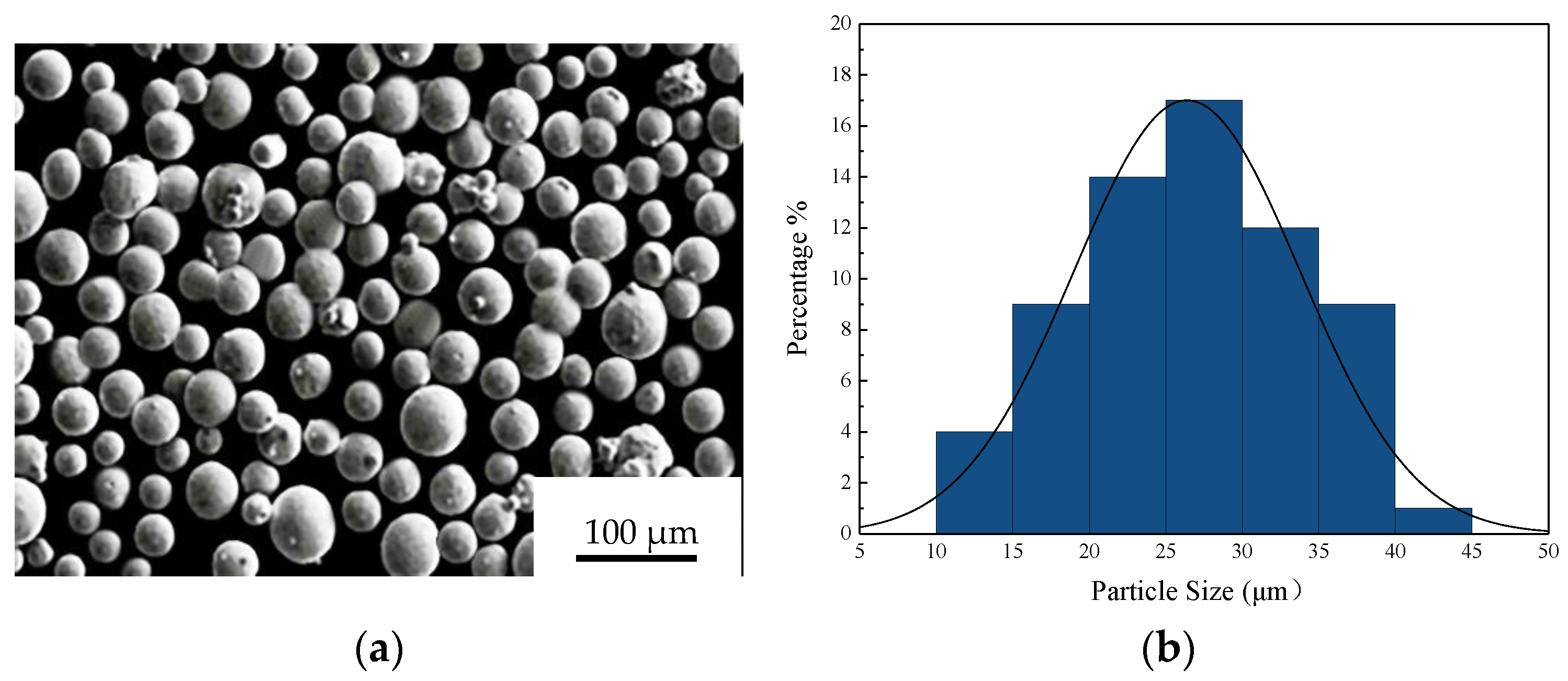
Figure 1. The 316L pellets and particle size: (a) SEM image of 316L pellets, (b) particle size distribution.
Metals 12 01712 g001
Figure 2. FCC structural porous bone scaffolds modeling process.
Metals 12 01712 g002
Figure 3. Scanning strategy.
Metals 12 01712 g003
Figure 4. XRD pattern of the stainless steel parts processed by SLM under different ω.
Metals 12 01712 g004
Figure 5. Organization of the porous bone scaffolds.
Metals 12 01712 g005
Figure 6. Organization of the melt pool with different energy densities: (a) ω = 41.7 J/mm3, (b) ω = 57.1 J/mm3, (c) ω = 67.7 J/mm3, (d) ω = 77.4 J/mm3, (e) ω = 83.3 J/mm3, (f) ω = 100.0 J/mm3, and (g) ω = 111.1 J/mm3.
Metals 12 01712 g006
Figure 7. Temperature and stress fields in the melt pool for different energy densities: (a,b) ω = 41.7 J/mm3, (c,d) ω = 67.7 J/mm3, (e,f) ω = 77.4 J/mm3, and (g,h) ω = 111.1 J/mm3.
Metals 12 01712 g007
Figure 8. Effect of different energy densities on the melt pool depth: (a) ω = 41.7 J/mm3 and (b) ω = 111.1 J/mm3.
Metals 12 01712 g008
Figure 9. Effect of energy densities on the primary dendrite spacing.
Metals 12 01712 g009
Figure 10. Distribution and magnitude of residual stress within the FCC structure: (a) before substrate removal, (b) after substrate removal.
Metals 12 01712 g010
Figure 11. Stress variation for different layers at an energy density of 41.7 J/mm3: (a) layer 1, (b) layer 4, (c) layer 8, and (d) layer 10.
Metals 12 01712 g011
Figure 12. Residual stress analysis results.
Metals 12 01712 g012
Figure 13. Deformation position of the FCC structure at different energy densities: (a) ω = 41.7 J/mm3, (b) ω = 111.1 J/mm3.
Metals 12 01712 g013
Figure 14. Deformation of the FCC structure and deformation: (a) SLM-formed scaffold deformation, (b) SLM-formed scaffold deformation position.
Metals 12 01712 g014
Figure 15. Microhardness of porous bone scaffolds.
Metals 12 01712 g015
Figure 16. Stress–strain curve of the FCC structure.
Metals 12 01712 g016
Table 1. Chemical compositions of the as-used 316L stainless steel pellets.
ElementFeCMnSiNiCrMoSP
Content (wt.%)Balance≤0.03≤2.0≤0.7512–1416–182–3≤0.03≤0.045
Table 2. Orthogonal parameter design.
RouteLaser Power
P (W)
Scanning Speed
V (mm/s)
Hatching Spacing
S (mm)
Energy Density
ω (J/mm3)
11005000.0683.3
21006000.1041.7
31007000.0844.6
41305000.1065.0
51306000.0867.7
61307000.0677.4
71605000.08100.0
81606000.06111.1
91607000.1057.1
Table 3. XRD data showing the 2θ values, intensity, and peak FWHM of the main peaks.
Sample2θ LocationIntensityPeak FWHM
Standard (PDF NO.33-0937)43.582--
41.7 J/mm343.52018910.355
65.0 J/mm343.56520800.331
77.4 J/mm343.56628950.317
111.1 J/mm343.56532010.295
Table 4. Theta angle between the grain and boundary tangent for different energy densities.
Energy Density ω (J/mm3)θ (°)
41.780.126
44.680.013
57.153.319
65.054.201
67.752.074
77.448.490
83.346.367
100.043.647
111.150.727
Table 5. Design dimensions and actual dimensions of the FCC structure.
Porous Bone Scaffolds123456789
Design diameter values (μm)250250250250250250250250250
Build diameter values (μm)322 ± 26297 ± 15310 ± 12310 ± 16322 ± 40322 ± 20328 ± 20331 ± 30314 ± 13
Table 6. Compression deformation process of the FCC structure.
Deformation ProcessInitial Stage
(I)
Intermediate Stage
(II)
Late Stage
(III)
ImageMetals 12 01712 i001Metals 12 01712 i002Metals 12 01712 i003
Table 7. Modulus of elasticity of the porous scaffolds.
Route123456789
Density (g/cm3)2.372.362.372.372.372.382.442.472.36
Modulus of elasticity (GPa)18.618.418.518.618.618.719.720.118.4
Publisher’s Note: MDPI stays neutral with regard to jurisdictional claims in published maps and institutional affiliations.