Article

Features of Cathodic Plasma Electrolytic Nitrocarburizing of Low-Carbon Steel in an Aqueous Electrolyte of Ammonium Nitrate and Glycerin

1
Department of High-Efficiency Machining Technologies, Moscow State University of Technology “STANKIN”, 127994 Moscow, Russia
2
Department of Mathematical and Natural Sciences, Kostroma State University, 156005 Kostroma, Russia
*
Author to whom correspondence should be addressed.
Metals 2022, 12(10), 1773; https://doi.org/10.3390/met12101773
Submission received: 5 September 2022 / Revised: 13 October 2022 / Accepted: 19 October 2022 / Published: 21 October 2022

Abstract

:
The possibility of using an aqueous non-toxic electrolyte of ammonium nitrate and glycerin for the cathodic plasma electrolytic nitrocarburizing of low-carbon steel is considered in this paper. Surface morphology and roughness, element and phase compositions, and microhardness of the modified layer were investigated. Kinetic calculations of the processes of nitrogen and carbon diffusion into the steel surface are proposed, taking into account their mutual influence. Wear resistance was studied under dry friction conditions with tool alloy steel as a counter-body. Corrosion studies are performed using potentiodynamic polarization curves in 3.5% sodium chloride solution. The plasma electrolytic nitrocarburizing in an aqueous electrolyte with ammonium nitrate and glycerin is established to increase surface hardness up to 980 HV due to the formation of a nitrocarburized layer with 1.35 ± 0.12% carbon and 0.32 ± 0.08% nitrogen concentration. The influence of erosion in electrolyte plasma and high-temperature oxidation on the morphology and surface roughness is shown. The presence of a dense oxide layer, low surface roughness, and high hardness of the diffusion layer favor a decrease in the friction coefficient by 1.3 times, weight wear by 1.8 times and corrosion current density by 1.4 times.

1. Introduction

The durability and reliability of machines, technological equipment, and tools is directly related to the materials used, the surface characteristics, and hardness and wear resistance, which can be significantly changed in various ways [1,2,3,4,5,6,7]. Improving the performance properties of metal parts, machine components, and technological equipment requires the development of technologies for the synthesis of new materials and surface modification. Plasma electrolytic treatment (PET) has proven to be an effective and economical method of modifying metal surfaces. PET technologies, including oxidation, polishing, and chemical-thermal diffusion saturation, are high-speed methods and make it possible to modify the surface by applying protective coatings or forming diffusion-hardened layers [8,9,10,11].
Among the technologies of chemical-thermal plasma electrolytic processing, the cathodic processing option has received the greatest distribution in the geography of research, when the workpiece is the cathode, and the working chamber is the anode. PET has received a wide application in the chemical-thermal treatment of low-carbon steels by carburizing and nitrocarburizing [12].
The X-ray analysis of low-carbon steels after their cathodic plasma electrolytic nitrocarburizing (PENC) usually reveals Fe2–3N iron nitride [13,14], iron carbides Fe3C [13,14,15] and Fe5C2 [14], as well as iron carbonitride Fe2–3(NC) [15]. The same phases are detected during the cathodic PENC of medium-carbon steels [16], but in some cases, Fe4N nitride and Fe[Fe(CN)6]3 iron carbonitride are observed [17]. Residual austenite and martensite after PENC with electrolyte quenching are formed in steel Q235 [14]. Iron oxides were detected during the PENC of medium-carbon steel in urea electrolyte (Fe2O3) [18] and DINI.8509 steel in urea electrolyte (Fe3O4) [19]. The surface microhardness of low-carbon steels after PENC, as a rule, is determined by the phase composition of the layer. The hardness value and layer thickness can be increased by increasing the voltage and duration of the cathodic treatment of low-carbon [14,15] or medium-carbon steels [16].
An increase in surface roughness is usually observed with an increase in the voltage and duration of the cathodic PENC. The PENC of medium-carbon steel in a boiling urea solution at 220 V for 9 min leads to an increase in roughness by more than 15 times [16]. The same regularity is observed with PENC of stainless steel in a urea electrolyte [20,21], which is explained by the destructive effect of electric discharges. It has been shown in many works that the increase in surface roughness accompanying the cathodic PENC does not hinder the decrease in steel wear. The main reason for the apparent contradiction is considered to be the increase in steel hardness after PENC. For example, an increase in the hardness of low-carbon steel after cathodic PENC in a solution of triethanolamine, glycerin and sodium carbonate makes it possible to avoid abrasive wear during friction with a bearing steel counter-body [22].
A feature of the electrolytes used for cathodic PET is their high alkalinity, including the use of alkaline solutions of potassium and sodium or their salts, and, which is common, low water content. In contrast to them, less toxic electrolytes are used in anodic PET, which consist only of aqueous solutions of substances, the atoms of which, during decomposition, will diffuse into the treated surface. For example, ammonium salts and organic water-soluble compounds are almost always used [23,24,25]. A feature of PET in aqueous solutions is always high-temperature oxidation of the surface due to intense evaporation of water, which leads not only to the formation of a diffusion layer with possible subsequent hardening by quenching, but also to the formation of an oxide coating. In this paper, it is proposed to use an aqueous electrolyte for cathodic PENC, previously used for anodic PENC, containing ammonium nitrate and glycerin [26]. Its use will improve the environmental friendliness of the production.
It should be noted that the analysis of works on the study of cathodic PET showed the absence of studies on the kinetics of diffusion processes, which has been sufficiently studied for the anodic treatment option.
Based on the foregoing, the purpose of this work is to study the possibility of using an aqueous electrolyte solution based on ammonium nitrate and glycerin for cathodic PENC of low-carbon steel to increase the wear resistance and corrosion resistance of the surface, as well as to study the kinetics of diffusion processes during the cathodic treatment of steel.

2. Materials and Methods

2.1. Samples Processing

Cylindrical samples of low-carbon steel (0.2 wt.% C) 10 mm in diameter and 15 mm in height were polished with sandpaper to the surface roughness of Ra = 1.00 ± 0.10 μm and cleaned with acetone in ultrasonic bath. The cathodic PENC was carried out at the sample temperature of 900 °C in ammonium nitrate (10 wt.%) and glycerin (10 wt.%) solution using cylindrical electrolyzer under conditions of longitudinal electrolyte flow around the sample [27]. Samples were connected to the negative output of a power supply. In the upper part of the chamber–anode, the electrolyte was overflowed over the edge into the pallet, from where it was then pumped through the heat exchanger at flow rate of 2.5 L/min. The temperature of electrolyte cooled with tap water was maintained equal to (30 ± 2) °C at the inlet to the electrolyzer. After applying the voltage of 80 V from DC power supply, the samples were immersed in the electrolyte followed by voltage correction to 94 V that achieve the specified sample temperature at a current strength of 13 A. The samples’ temperature was measured with the accuracy of 2% by M89-K1 chromel-alumel thermocouple connected to MS-8221 multimeter. The thermocouple was installed in the hole on the axis inside the sample at the distance of 2 mm from the heated surface. Diffusion saturation was carried out for 5, 10, 20, and 30 min (5 samples for each point), after which the samples were cooled in the electrolyte (quenched) from the saturation temperature when voltage was disconnected. Then, samples were washed with water and dried.

2.2. Surface Characterization

The phase composition of the surface layers was investigated using the diffractometer with Co Kα radiation and scanning in the Θ/2Θ mode with a step of 0.1° and the rate of 1.25°/min.
Quanta 3D 200i scanning electron microscopy (FEI Company, Hillsboro, USA) (SEM) with an energy-dispersive spectroscope and a silicon drift detector (Apollo X, Amptek Inc., Bedford, USA) was used to observe the structure of the surface layer of the samples and for the subsequent elemental microanalysis after polishing and etching with the use of a 4% nitric acid solution in ethanol for 5–10 s.
The Micromed MET (Micromed, Russia) optical metallographic microscope with digital image visualization served to study the surface morphology.
The microhardness of the cross sections of the treatment sample was measured using a Vickers microhardness tester (Falcon 503, Innovatest Europe BV, Netherlands) under a 0.1-N load. Seven indentations were performed on each sample, and five points average value except both maximum and minimum values were used for hardness.
The surface roughness was measured with the TR-200 profilometer (Beijing TIME High Technology Ltd., China). The change in the weight of samples was determined on the CitizonCY224C electronic analytical balance (ACZET (Citizen Scale), India) with an accuracy of ±0.0001 g after washing the samples with distilled water to remove traces of salts and subsequently drying.
The corrosion resistance of samples was estimated at potentiodynamic polarization in sodium chloride (3.5%) solution using a Biologic SP-150 (ST Instruments, Netherlands) potentiostat-galvanostat in a standard three-electrode cell at the scan rate of 1 mV/s. Before corrosion testing, samples were cleaned with acetone in the ultrasonic bath for 5 min, then washed with distilled water and dried until their weight stabilized. Further, the surface of samples was insulated by a dielectric mask with a circular aperture with of 0.125 mm2 area located at the distance of 2 mm from the lower edge of the sample. Graphite was used as the auxiliary electrode. The saturated silver chloride electrode served as the reference one. The working electrode (sample) was kept in sodium chloride (3.5%) solution for 60 min before testing to steady the constant value of corrosion potential. The corrosion current density was determined by Tafel’s extrapolation of polarization curves with the aid of EC-Lab program.
The friction scheme “shaft-block” was used in friction tests (Figure 1). The counter body was made of tool alloy steel (wt.%: 0.9–1.2 Cr, 1.2–1.6 W, 0.8–1.1 Mn, 0.9–1.05 C) in the form of a plate with a semicircular notch 10 mm in diameter, enclosing the surface of the sample. The sample was mounted on a shaft driven by an electric motor. The counter body was mounted on a platform sliding along cylindrical guides. The platform was moved using a pneumatic cylinder. The cylinder, guides, and platform were able to rotate with the pendulum. The pendulum shaft was located coaxially with the sample. Such a scheme makes it possible to preserve the common rotation axis for the sample and the counter body as they wear out and to avoid the influence of misalignment on the results of measurements of the frictional moment. Friction tests were carried out in dry friction mode under a load of 10 N. The sliding speed of the sample along the counter body was 1.555 m/s. The friction path was 1000 m. The friction tracks images were obtained using a Quanta 3D 200i scanning electron microscope. The elemental composition on the friction track was determined using energy dispersive spectroscopy.

3. Results

3.1. Morphology, Phase Composition, and Roughness of the Surface

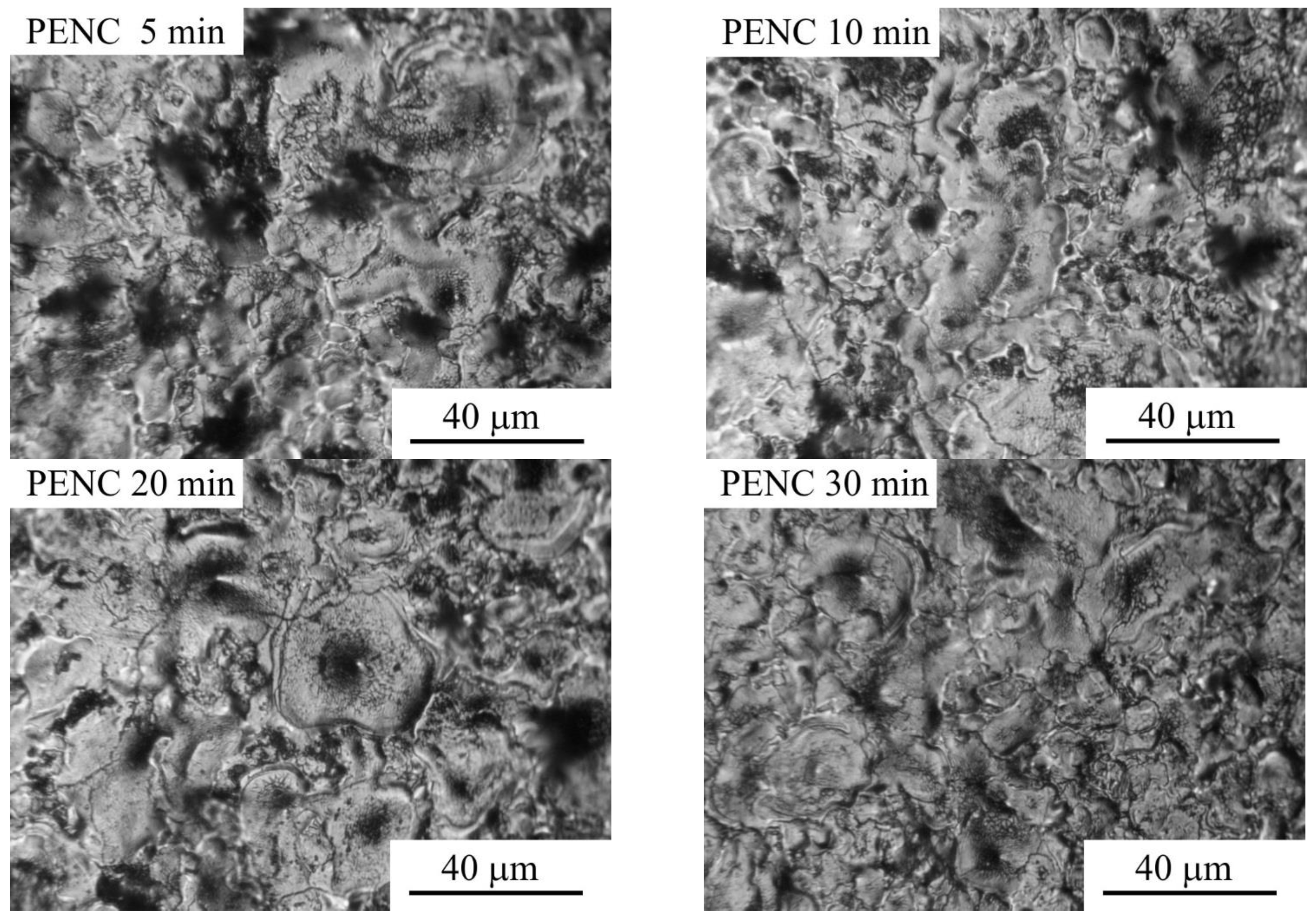
The change in the morphology of the steel surface during PENC is associated with the occurrence of high-temperature oxidation and erosion of the surface, which are characteristic of cathodic PET in aqueous electrolytes [28]. The high-temperature oxidation of the surface leads to the formation of an oxide layer, which, according to X-ray analysis, consists of FeO, Fe2O3, and Fe3O4 oxides (Figure 2). Under the action of electrical discharges, the outer layer is eroded, which leads to the formation of craters (Figure 3).
With an increase in the duration of treatment, a linear increase in the weight loss of samples under the destructive action of discharges is observed, the surface roughness increases after 5 min and then decreases to 1.5 times after 30 min of treatment (Table 1).

3.2. Cross-Sectional SEM and EDX Analysis of PENC Samples

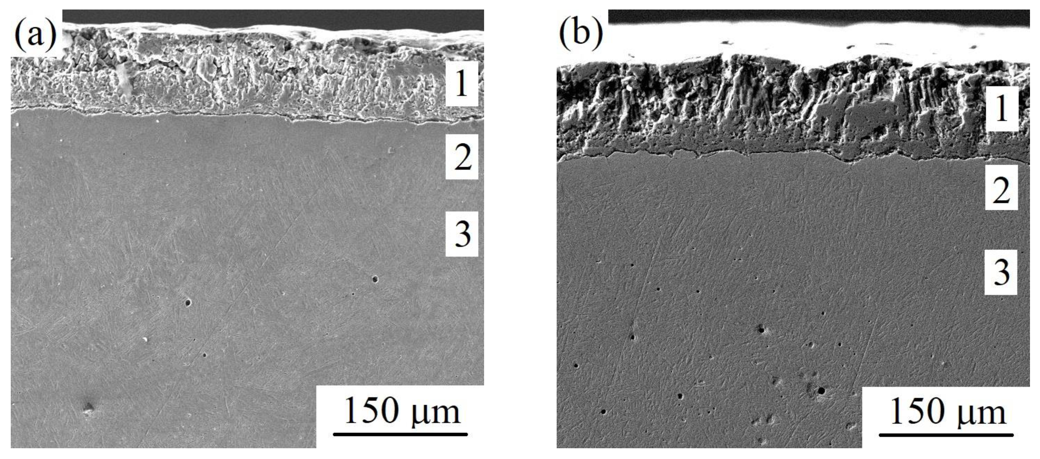
According to SEM analysis, during cathodic PENC, oxide and diffusion nitrocarburised layers are formed on the surface of steel (Figure 4). Cross-sectional SEM images reveal a high porosity of the oxide layer from the outside and a dense structure inside, while the thickness of the dense structure increases with the treatment time. As a result of the action of electrical discharges and the removal of the loose part of the oxide layer, the total thickness of the oxide layer remains within 100 μm. The outer loose part of the oxide layer mainly with Fe2O3 phases has a microhardness of 150 ± 30 HV; the inner dense part of the oxide layer mainly with FeO phases has a microhardness of 200 ± 35 HV. Clear boundaries of the diffusion layer were not found, that is, its thickness cannot be estimated from the SEM image. The thicknesses of the diffusion layers can be determined more precisely from the microhardness values. However, in this case, one should speak about the thickness of the hardened layer.
According to the EDX analysis data, the characteristic of the diffusion of light elements their depth distribution is observed in the formed nitrocarburized layer (Figure 5 and Figure 6). The concentrations of all elements and the depth of their penetration increase with increasing duration of diffusion saturation and reach 1.35 ± 0.12% carbon and 0.32 ± 0.08% nitrogen. The high concentration of nitrogen is confirmed by the identification of nitrides in the X-ray analysis (Figure 2).

3.3. Calculation of the Diffusion Coefficients of Nitrogen and Carbon

Based on the obtained distribution profiles of diffusing elements concentration, the diffusion coefficients were calculated using two methods.
In the first case, the mutual influence of diffusant atoms on their diffusion was not taken into account (method 1). In interstitial solid solutions, in contrast to substitutional solid solutions, it is permissible to assume the diffusion of only one diffusing element. This case is described by the mathematical model below.
The differential equation of diffusion in a semi-infinite body is solved:
C ( x , τ ) τ = D 2 C ( x , τ ) x 2 ,
where C is the concentration of the diffusing element (wt. %); x is horizontal coordinate (m); τ is time (s); and D is the diffusion coefficient (m2/s). Under the following boundary conditions:
C ( x , 0 ) = C 0 ; C ( 0 , τ ) = C S ; C ( , τ ) = C 0 ,
where C0 is the initial concentration of the element in the sample material and CS is the concentration of the element on the sample surface.
The solution of Equation (1) under the indicated conditions is known:
C ( x , τ ) = C S ( C S C 0 ) e r f x 2 D τ .
To determine the unknown diffusion coefficients Dj of carbon (C) and nitrogen (N), the least squares method was used.
The coefficients Dj were selected in such a way as to provide the smallest value for the sum of squared deviations of the theoretical values of concentrations according to Equation (1) from its experimental values. That is, the following condition must be met:
F ( D j ) = i = 1 n [ C i S ( C i S C i 0 ) e r f ( x i 2 D j τ ) C i ( x , τ ) ] 2 = min .
To determine the minimum value of the functional F(Dj), it is necessary to equate its partial derivative with respect to the variable Dj to zero.
As a result, we obtained:
F ( D j ) D j = 2 i = 1 n [ C i S ( C i S C i 0 ) e r f ( x i 2 D j τ ) C i ( x , τ ) ] × exp ( x i 2 4 D j τ ) ( C i S C i 0 ) x i 2 D j 3 τ .
From here, we obtained an equation for determining the unknown coefficients Dj for all diffusants:
i = 1 n ( C i S C i ( x , τ ) ) x i exp ( x i 2 4 D j τ ) ( C i S C i 0 ) i = 1 n x i exp ( x i 2 4 D j τ ) e r f ( x i 2 D j τ ) = 0 .
The results of the graphical solution of this equation are presented in Table 2.
The mutual influence of the fluxes of nitrogen and carbon atoms on each other leads to the appearance of off-diagonal diffusion coefficients other than zero (method 2).
The system of differential equations for multicomponent diffusion is solved:
c i τ = m = 1 N D i m 2 c m x 2 .
Initial and boundary conditions:
c i ( x , 0 ) = c i 0 ; c i ( 0 , τ ) = c i ; c i ( , τ ) = c i 0 .
Instead of ci(x,τ), we introduced the functions yi(x,τ) in accordance with the equality:
y i ( x , τ ) = c i ( x , τ ) c i .
Substituting (9) into (7), we obtained a new system of equations,
y i τ = m = 1 N D i m 2 y m x 2 ,
which must be solved under the following initial and boundary conditions:
y i ( x , 0 ) = c i 0 c i = B i ; y i ( 0 , τ ) = 0 ; y i ( , τ ) = c i 0 c i = B i .
We multiplied both sides of Equation (10) by some constant factors aij and summed over the second index:
j = 1 N a i j y i τ = j = 1 N a i j m = 1 N D j m 2 y m x 2 = m = 1 N ( j = 1 N a i j D j m ) 2 y m x 2
Imposing the conditions on the coefficients aij
j = 1 N a i j D j m = D i a i m ,
and introducing new features
Y i ( x , τ ) = m = 1 N a i m y m ( x , τ ) ,
we obtained a new system of independent equations
Y i τ = D i 2 Y i x 2
with initial and boundary conditions:
Y i ( x , 0 ) = B i m = 1 N a i m ; Y i ( 0 , τ ) = 0 ; Y i ( , τ ) = B i m = 1 N a i m .
Under these conditions, Equation (15) has unique and continuous solutions of the form:
Y i ( x , τ ) = B i ( m = 1 N a i m ) e r f ( x 2 D i τ ) .
Let us introduce the notation:
k i = 1 2 D i τ .
Then, (17) can be rewritten in the form:
Y i ( x , τ ) = B i ( m = 1 N a i m ) e r f ( k i x ) .
Using Formulas (14) and (19), we can write:
m = 1 N a i m [ y m ( x , τ ) B i e r f ( k i x ) ] = 0 .
For given points xk on the experimental curves ci(x,τ) constructed for a fixed point in time, we obtained a system of equations:
m = 1 N a i m [ y m ( x k ) B i e r f ( k i x k ) ] = 0 ,
which is resolvable at aim ≠ 0 if:
| y m ( x k ) e r f ( k i x k ) | = 0 .
In the last formula, only ki is unknown, so it can be considered as a system of equations for determining ki.
For a three-component system, after calculations, we obtained:
e r f ( k x 1 ) [ y 2 ( x 2 ) y 1 ( x 2 ) B 2 B 1 ] e r f ( k x 2 ) [ y 2 ( x 1 ) y 1 ( x 1 ) B 2 B 1 ] = 1 B 1 | y 1 ( x 1 ) y 2 ( x 1 ) y 1 ( x 2 ) y 2 ( x 2 ) | .
By solving Equation (23) one can find two different roots k1, k2, and then, using (18), determine two values D1, D2. Then, for known k, from Equation (21), we found aim.
a 11 [ y 1 ( x 1 ) B 1 e r f ( k 1 x 1 ) ] + a 12 [ y 2 ( x 1 ) B 2 e r f ( k 1 x 1 ) ] = 0 ; a 11 [ y 1 ( x 2 ) B 1 e r f ( k 1 x 2 ) ] + a 12 [ y 2 ( x 2 ) B 2 e r f ( k 1 x 2 ) ] = 0 .
From System (24), a11/a12 = m was found:
a 21 [ y 1 ( x 1 ) B 1 e r f ( k 2 x 1 ) ] + a 22 [ y 2 ( x 1 ) B 2 e r f ( k 2 x 1 ) ] = 0 ; a 21 [ y 1 ( x 2 ) B 1 e r f ( k 2 x 2 ) ] + a 22 [ y 2 ( x 2 ) B 2 e r f ( k 2 x 2 ) ] = 0 .
From System (25), a21/a22 = n was found:
Further, from System (13), the diffusion coefficients were found (Table 3):
D 11 = m D 1 n D 2 m n ; D 12 = D 1 D 2 m n ; D 21 = m n ( D 2 D 1 ) m n ; D 22 = m D 2 n D 1 m n .
The coefficients D11 and D22 are the intrinsic diffusion coefficients of carbon and nitrogen in iron. The coefficient D12 is the kinetic diffusion coefficient, reflecting the effect of nitrogen diffusion on the diffusion of carbon, and the coefficient D21 is the kinetic diffusion coefficient, which describes the effect of the flow of carbon atoms on the nitrogen flow.

3.4. Microhardness of the Diffusion of the Nitrocarburized Layer

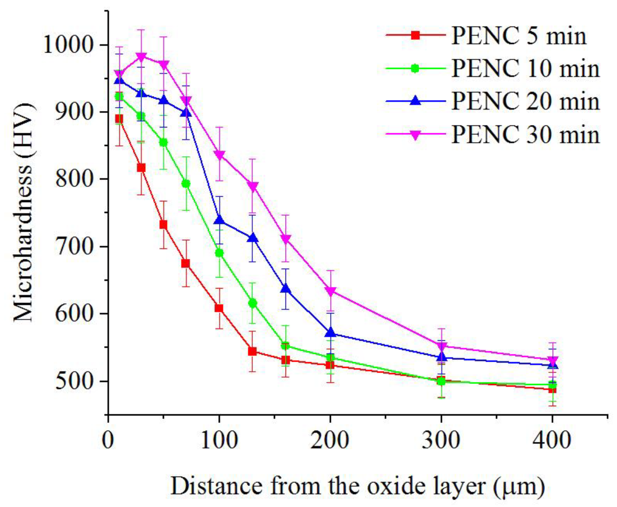
The consequence of diffusion saturation of the surface layer and quenching is an increase in microhardness up to 980 ± 20 HV (Figure 7). With an increase in the PENC duration, the thickness of the hardened zone increases from 130 to 300 μm.

3.5. Tribological Properties of the PENC Surface

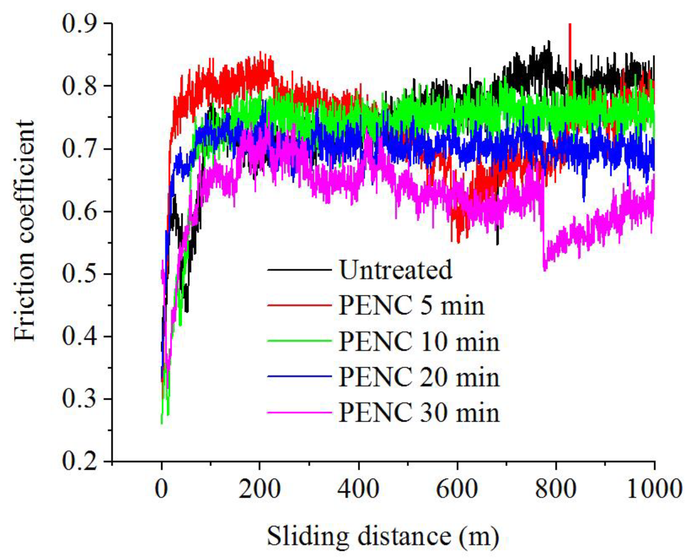
The results of tribological tests showed a positive effect of the PENC duration on the reduction in the friction coefficient and weight wear (Table 1, Figure 8).
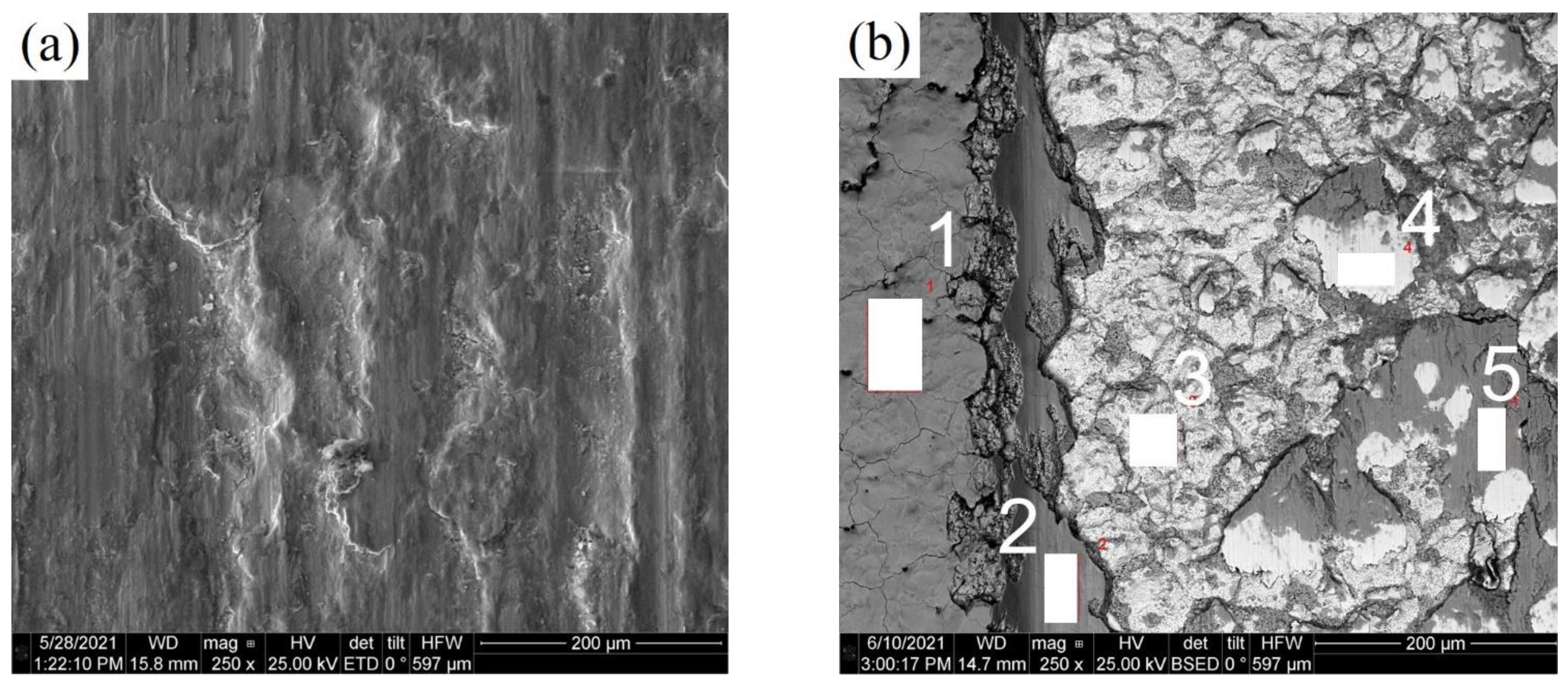
The morphological analysis of the friction track (Figure 9) showed the absence of traces of abrasive wear characteristics in the untreated samples.
Based on the data of EDX analysis on the friction track, the elements included in the composition of the counter body (Si, Cr, Mn, Ni, and Cu), nitrogen and carbon that diffused into the sample were identified (Table 4). The nitrogen concentration in scan areas 3 and 4 coincides with the data obtained from the analysis of the cross section of the sample (Figure 5), which makes it possible to judge the exposure of the diffusion layer. Areas 2 and 5 are the remnants of the oxide layer, which have not been completely destroyed during friction. They retain the oxygen content characteristic of the initial oxide layer (scan area 1).

3.6. Corrosion Properties of the PENC Surface

With cathodic PENC, in general, there is a tendency to reduce corrosion resistance except for PENC samples for 20 min. In this case, a decrease in the corrosion current density by 1.4 times is observed compared to untreated steel (Table 1, Figure 10).

4. Discussion

As a result of the cathodic PENC in an aqueous electrolyte based on glycerin and ammonium nitrate, a modified layer formed on the steel surface, which consists of an outer oxide layer and a diffusion hardened layer.
The competition between high-temperature oxidation and surface erosion under the action of electric discharges determines the morphology and roughness of the surface. The increase in roughness after 5 min of treatment and its subsequent decrease to 1.5 times after 30 min of treatment is explained by the selective destruction of less durable sections of the oxide layer by discharges, as a result of which, during long-term treatment, a stronger surface layer is preserved, which will be less susceptible to destruction. The compaction of the oxide layer with increasing treatment time is confirmed by the SEM data.
For the formed diffusion layer, a typical distribution of atoms of diffusing elements in the surface layer was revealed, which, as a result, determines the nature of the distribution of microhardness. The calculation of diffusion coefficients showed the mutual influence of diffusant atoms on diffusion. It is shown that the cross diffusion coefficient D12, which describes the effect of nitrogen diffusion on carbon diffusion, is positive. This indicates that nitrogen increases the thermodynamic activity of carbon in austenite. The cross coefficient D21, which reflects the effect of the diffusion of carbon atoms on the diffusion of nitrogen atoms, is also positive. That is, carbon, in turn, also leads to an increase in the thermodynamic activity of nitrogen. Thus, carbon and nitrogen displace each other and thereby increase their thermodynamic activity. From a comparison of the values of the diffusion coefficients of one carbon and the simultaneous diffusion of nitrogen and carbon, it can be seen that the presence of nitrogen accelerates the diffusion of carbon, as well as vice versa. This is due to a decrease in the temperatures of the transformation of pearlite and ferrite into austenite in the presence of nitrogen and, as a consequence, with the formation of a larger proportion of austenite in the steel structure and a high solubility of carbon in the latter.
Patterns of changes in the morphology and roughness of the surface, as well as the thickness of the hardened diffusion layer in the process of PENC, determine the nature of the change in the coefficient of friction and wear. The resulting oxide layer, regardless of the duration of treatment, participates in the friction pair as a lubricant, favoring the sliding of the counter body over the surface and reducing the friction coefficient. The growth in roughness in the first 5 min of PENC contributes to the removal of material during friction and a slight increase in weight wear. After PENC for 20 and 30 min, when the roughness decreases and the thickness of the hardened layer becomes larger, a decrease in weight wear by a factor of 2 is observed. Based on the analysis of the morphology of the friction track, it was possible to determine the mechanism of destruction of rubbing irregularities by fatigue, as was established after anodic PENC of steel [29].
The development of the surface relief due to the formation of craters and pores increases the area of contact with the corrosive medium and the possibility of adsorption of corrosive agents, which leads to an increase in the current density. The decrease in the corrosion current density after 20 min of treatment may be due to the denser homogeneous morphology of the oxide layer, which performs a protective function.

5. Conclusions

1. The possibility of using aqueous electrolytes for cathodic PET of steels previously used for anodic treatment with correction of component concentrations was shown (by the example of an aqueous solution of ammonium nitrate and glycerin).
2. The competing influence of surface erosion by the action of microdischarges, which leads to the formation of microcraters and a decrease in the weight of samples with an increase in roughness, and high-temperature oxidation, which contributes to the filling of pores and craters with oxides with a subsequent decrease in roughness, was established.
3. The diffusion coefficients of atoms of the saturating components were calculated, on the basis of which the mutual influence of diffusants on the increase in their thermodynamic activity in austenite was shown, i.e., acceleration of the diffusion process. It was shown that, as a result of diffusion saturation of the surface layer and quenching, the microhardness increases to 980 ± 20 HV. The microhardness and thickness of the hardened layer correlate with the intensity of diffusion processes.
4. The results of tribological tests with dry friction show the possibility of reducing the friction coefficient by 1.3 times and weight wear by 1.8 times. Based on the analysis of the influence of the structure and morphology of the surface on its tribological behavior, one should speak about the complex effect of the hardness of the diffusion layer as a substrate and the nature of the triboconjugation of the oxide layer with the counter body.
5. The effect of oxide layer morphology on corrosion resistance was shown. An increase in corrosion resistance is possible only with the formation of a dense surface oxide layer uniform in morphology.
6. The maximum microhardness and thickness of the hardened layer were achieved after cathodic PENC for 30 min. The best wear resistance and corrosion resistance were achieved after treatment for 20 min. That is why the optimal time of cathodic PENC is processing for 20 min, because in this case the best combination of surface characteristics and performance properties was observed. The results obtained will form the basis for studying the efficiency of surface modification of materials by cathodic plasma electrolytic treatment followed by anode plasma electrolytic polishing.

Author Contributions

Conceptualization, I.T. and S.K.; methodology, I.T., T.M., I.S. and S.K.; validation, S.G.; formal analysis, I.S.; investigation, T.M., I.G., S.S. and I.D.; writing—original draft preparation, I.T.; writing—review and editing, I.S. and S.K.; visualization, S.K.; supervision, I.S.; project administration, S.G.; funding acquisition, S.G. All authors have read and agreed to the published version of the manuscript.

Funding

This work was supported financially by the Ministry of Science and Higher Education of the Russian Federation (project No 0707-2020-0025). The study was carried out on the equipment of the Center of collective use of MSUT “STANKIN” supported by the Ministry of Higher Education of the Russian Federation (project No. 075-15-2021-695 from 26.07.2021, unique identifier RF----2296.61321X0013).

Institutional Review Board Statement

Not applicable.

Informed Consent Statement

Not applicable.

Data Availability Statement

Not applicable.

Conflicts of Interest

The authors declare no conflict of interest.

References

  1. Metel, A.S.; Grigoriev, S.N.; Melnik, Y.A.; Panin, V.V. Filling the vacuum chamber of a technological system with homogeneous plasma using a stationary glow discharge. Plasma Phys. Rep. 2009, 35, 1058–1067. [Google Scholar] [CrossRef]
  2. Grigoriev, S.N.; Sinopalnikov, V.A.; Tereshin, M.V.; Gurin, V.D. Control of parameters of the cutting process on the basis of diagnostics of the machine tool and workpiece. Meas. Tech. 2012, 55, 555–558. [Google Scholar] [CrossRef]
  3. Grigoriev, S.N.; Vereschaka, A.A.; Fyodorov, S.V.; Sitnikov, N.N.; Batako, A.D. Comparative analysis of cutting properties and nature of wear of carbide cutting tools with multi-layered nano-structured and gradient coatings produced by using of various deposition methods. Int. J. Adv. Manuf. Technol. 2017, 90, 3421–3435. [Google Scholar] [CrossRef]
  4. Volosova, M.; Grigoriev, S.; Metel, A.; Shein, A. The Role of Thin-Film Vacuum-Plasma Coatings and Their Influence on the Efficiency of Ceramic Cutting Inserts. Coatings 2018, 8, 287. [Google Scholar] [CrossRef] [Green Version]
  5. Grigoriev, S.N.; Volosova, M.A.; Okunkova, A.A.; Fedorov, S.V.; Hamdy, K.; Podrabinnik, P.A.; Pivkin, P.M.; Kozochkin, M.P.; Porvatov, A.N. Electrical Discharge Machining of Oxide Nanocomposite: Nanomodification of Surface and Subsurface Layers. J. Manuf. Mater. Process. 2020, 4, 96. [Google Scholar] [CrossRef]
  6. Apelfeld, A.; Grigoriev, S.; Krit, B.; Ludin, V.; Suminov, I.; Chudinov, D. Improving the stability of the coating properties for group plasma electrolytic oxidation. Manuf. Lett. 2022, 33, 54–59. [Google Scholar] [CrossRef]
  7. Grigoriev, S.N.; Kondratsky, I.O.; Krit, B.L.; Ludin, V.B.; Medvetskova, V.M.; Morozova, N.V.; Suminov, I.V.; Apelfeld, A.V.; Wu, R.Z. Protective and Thermophysical Characteristics of Plasma-Electrolytic Coatings on the Ultralight Magnesium Alloy. J. Eng. Mater. Technol. 2022, 144, 021006. [Google Scholar] [CrossRef]
  8. Yerokhin, A.L.; Nie, X.; Leyland, A.; Matthews, A.; Dowey, S.J. Plasma electrolysis for surface engineering. Surf. Coat. Technol. 1999, 122, 73–93. [Google Scholar] [CrossRef]
  9. Aliofkhazraei, M.; Macdonald, D.D.; Matykina, E.; Parfenov, E.V.; Egorkin, V.S.; Curran, J.A.; Troughton, S.C.; Sinebryukhov, S.L.; Gnedenkov, S.V.; Lampke, T.; et al. Review of plasma electrolytic oxidation of titanium substrates: Mechanism, properties, applications and limitations. Appl. Surf. Sci. Advances 2021, 5, 100121. [Google Scholar] [CrossRef]
  10. Jin, S.; Ma, X.; Wu, R.; Wang, G.; Zhang, J.; Krit, B.; Betsofen, S.; Liu, B. Advances in micro-arc oxidation coatings on Mg-Li alloys. Appl. Surf. Sci. Adv. 2022, 8, 100219. [Google Scholar] [CrossRef]
  11. Bogdashkina, N.L.; Gerasimov, M.V.; Zalavutdinov, R.K.; Kasatkina, I.V.; Krit, B.L.; Lyudin, V.B.; Fedichkin, I.D.; Shcherbakov, A.I.; Apelfeld, A.V. Influence of Nickel Sulfate Additives to Electrolytes Subjected to Microarc Oxidation on the Structure, Composition, and Properties of Coatings Formed on Titanium. Surf. Eng. Appl. Electrochem. 2018, 54, 331–337. [Google Scholar] [CrossRef]
  12. Belkin, P.N.; Yerokhin, A.; Kusmanov, S.A. Plasma Electrolytic Saturation of Steels with Nitrogen and Carbon. Surf. Coat. Technol. 2016, 307, 1194–1218. [Google Scholar] [CrossRef]
  13. Jiang, Y.-F.; Bao, Y.-F.; Yang, K. Effect of C/N concentration fluctuation on formation of plasma electrolytic carbonitriding coating on Q235. J. Iron Steel Res. Int. Vol. 2012, 19, 39–45. [Google Scholar] [CrossRef]
  14. Shen, D.-J.; Wang, Y.-L.; Nash, P.; Xing, G.-Z. A novel method of surface modification for steel by plasma electrolysis carbonitriding. Mater. Sci. Eng. A 2007, 458, 240–243. [Google Scholar] [CrossRef]
  15. Zarchi, M.K.; Shariat, M.H.; Dehghan, S.A.; Solhjoo, S. Characterization of nitrocarburized surface layer on AISI 1020 steel by electrolytic plasma processing in an urea electrolyte. J. Mater. Res. Technol. 2013, 2, 213–220. [Google Scholar] [CrossRef] [Green Version]
  16. Rastkar, A.R.; Shokri, B. Surface modification and wear test of carbon steel by plasma electrolytic nitrocarburizing. Surf. Interface Anal. 2012, 44, 342–351. [Google Scholar] [CrossRef]
  17. Noori, S.M.; Dehghanian, C. Corrosion behavior of nitrocarburized coating on AISI 1045 steel deposited by Plasma Electrolytic Saturation. In Proceedings of the 5th International Conference on Materials Engineering and Metallurgy, Shiraz, Iran, 8–9 November 2016. [Google Scholar]
  18. Sheng, Y.; Zhang, Z.; Li, W. Effects of pulse frequency and duty cycle on the plasma discharge characteristics and surface microstructure of carbon steel by plasma electrolytic nitrocarburizing. Surf. Coat. Technol. 2017, 330, 113–120. [Google Scholar] [CrossRef]
  19. Tavakoli, H.; Mousavi Khoie, S.M.; Marashi, S.P.H.; Bolhasani, O. Effect of Electrolyte Composition on Characteristics of Plasma Electrolysis Nitrocarburizing. J. Mater. Eng. Perform. 2013, 22, 2351–2358. [Google Scholar] [CrossRef]
  20. Tsotsos, C.; Yerokhin, A.L.; Wilson, A.D.; Leyland, A.; Matthews, A. Tribological evaluation of AISI 304 stainless steel duplex treated by plasma electrolytic nitrocarburising and diamond-like carbon coating. Wear 2002, 253, 986–993. [Google Scholar] [CrossRef]
  21. Kazerooni, N.A.; Bahrololoom, M.E.; Shariat, M.H.; Mahzoon, F.; Jozaghi, T. Effect of Ringer’s solution on wear and friction of stainless steel 316L after plasma electrolytic nitrocarburising at low voltages. J. Mater. Sci. Technol. 2011, 27, 906–912. [Google Scholar] [CrossRef]
  22. Jiang, Y.; Bao, Y.; Yang, K. Formation and friction behavior of plasma electrolytically nitrocarburized surface layers on Q235 steel. Surf. Coat. Technol. 2015, 269, 324–328. [Google Scholar] [CrossRef]
  23. Kusmanov, S.A.; Silkin, S.A.; Smirnov, A.A.; Belkin, P.N. Possibilities of increasing wear resistance of steel surface by plasma electrolytic treatment. Wear 2017, 386–387, 239–246. [Google Scholar] [CrossRef]
  24. Kusmanov, S.A.; Smirnov, A.A.; Silkin, S.A.; Belkin, P.N. Increasing wear and corrosion resistance of low-alloy steel by anode plasma electrolytic nitriding. Surf. Coat. Technol. 2016, 307, 1350–1356. [Google Scholar] [CrossRef]
  25. Kusmanov, S.A.; Kusmanova, Y.V.; Smirnov, A.A.; Belkin, P.N. Modification of steel surface by plasma electrolytic saturation with nitrogen and carbon. Mater. Chem. Phys. 2016, 175, 164–171. [Google Scholar] [CrossRef]
  26. Kusmanov, S.A.; Dyakov, I.G.; Kusmanova, Y.V.; Belkin, P.N. Surface Modification of Low-Carbon Steels by Plasma Electrolytic Nitrocarburising. Plasma Chem. Plasma Process. 2016, 36, 1271–1286. [Google Scholar] [CrossRef]
  27. Smirnov, A.A.; Kusmanov, S.A.; Kusmanova, I.A.; Belkin, P.N. Effect of Electrolyte Depletion on the Characteristics of the Anodic Plasma Electrolytic Nitriding of a VT22 Titanium Alloy. Surf. Eng. Appl. Electrochem. 2017, 53, 413–418. [Google Scholar] [CrossRef]
  28. Kusmanov, S.A.; Tambovskiy, I.V.; Gorokhov, I.S.; Belkin, P.N. Plasma Electrolytic Polishing Effect on Steel’s Surface Roughness after Cathodic Saturation with Nitrogen and Carbon. Surf. Eng. Appl. Electrochem. 2021, 57, 513–518. [Google Scholar] [CrossRef]
  29. Mukhacheva, T.L.; Belkin, P.N.; Dyakov, I.G.; Kusmanov, S.A. Wear mechanism of medium carbon steel after its plasma electrolytic nitrocarburising. Wear 2020, 462–463, 203516. [Google Scholar] [CrossRef]
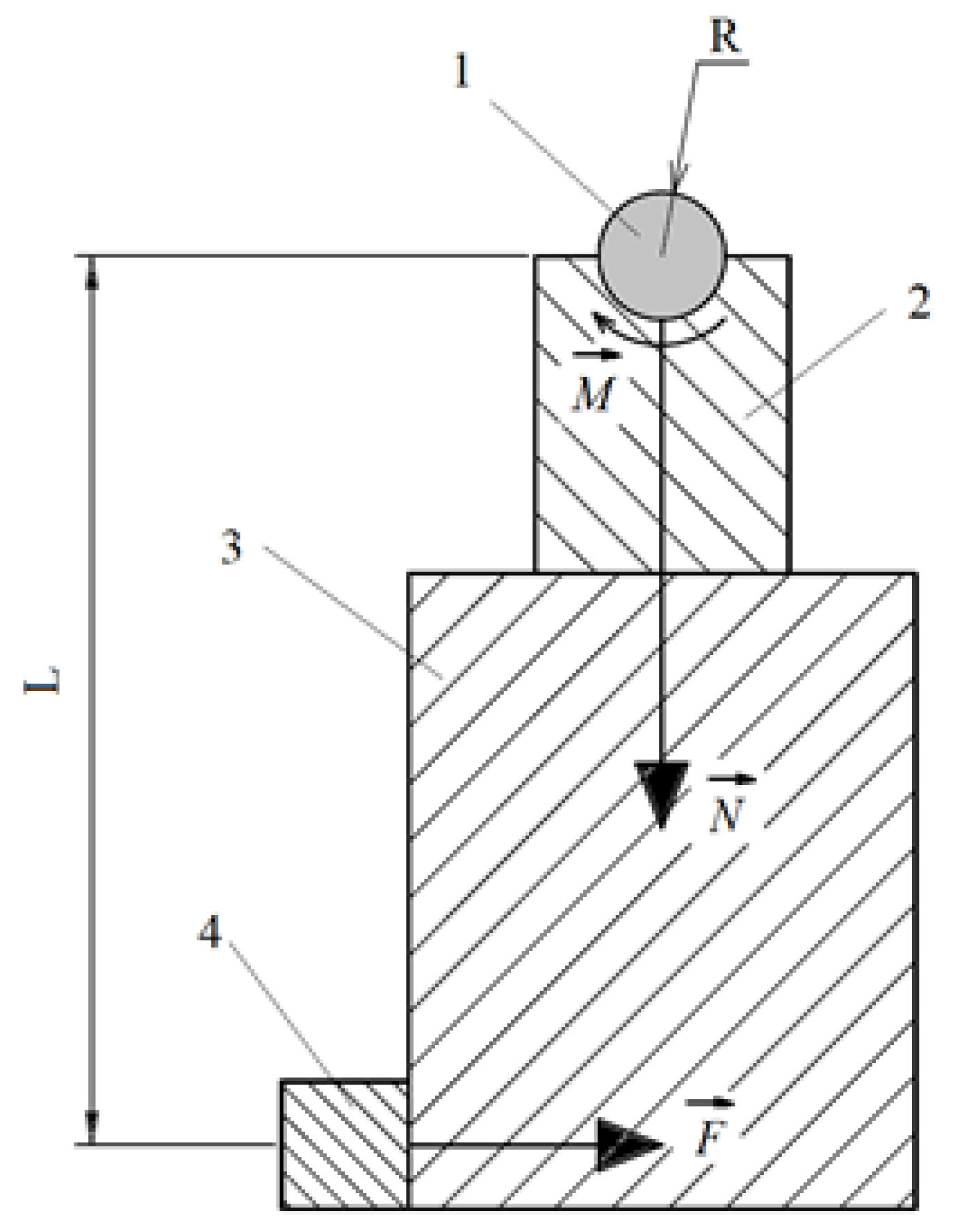
Figure 1. Friction scheme. 1—sample; 2—counter-body; 3—pendulum; 4—strain gauge. M—frictional moment; N—force acting on the counter body and the pendulum from the side of the sample; F—force acting on the pendulum from the strain gauge; L—distance from the axis of rotation to the axis of symmetry of the strain gauge.
Metals 12 01773 g001
Figure 2. X-ray diffraction patterns of the steel surface layer after cathodic PENC.
Metals 12 01773 g002
Figure 3. Morphology of the steel surface after cathodic PENC.
Metals 12 01773 g003
Figure 4. SEM image of cross-section of the steel surface after cathodic PENC for: (a)—5 min, (b)—10 min, (c)—20 min, (d)—30 min. The numbers on the images indicate: 1—oxide layer; 2—diffusion nitrocarburized layer; 3—initial structure.
Metals 12 01773 g004aMetals 12 01773 g004b
Figure 5. EDX nitrogen distributions in the nitrocarburzsed layer after cathodic PENC.
Metals 12 01773 g005
Figure 6. EDX carbon distributions in the nitrocarburized layer after cathodic PENC.
Metals 12 01773 g006
Figure 7. Microhardness distribution in the nitrocarburized layer after cathodic PENC.
Metals 12 01773 g007
Figure 8. The dependence of the friction coefficient on the sliding distance of the untreated and PENC samples.
Metals 12 01773 g008
Figure 9. SEM image of wear tracks of the steel surface before (a) and after cathodic PENC for 30 min (b).
Metals 12 01773 g009
Figure 10. Polarization curves of the untreated and PENC samples.
Metals 12 01773 g010
Table 1. Conditions of PENC and results of the samples’ testing.
PENC Time (min)Weight Loss of Samples during PENC (mg)Surface Roughness, Ra (μm)Average Friction Coefficient for the Last 100 m of TrackWeight Loss of Samples during Tribological Test (mg)Corrosion Current Density (μA/cm2)
Untreated1.00 ± 0.100.824 ± 0.01514.0 ± 0.322.8 ± 4.0
529 ± 41.38 ± 0.320.730 ± 0.01216.0 ± 0.331.9 ± 4.2
1074 ± 60.94 ± 0.180.736 ± 0.01216.5 ± 0.332.4 ± 4.1
20177 ± 40.77 ± 0.250.694 ± 0.0118.0 ± 0.216.4 ± 3.2
30276 ± 80.66 ± 0.060.621 ± 0.0108.0 ± 0.239.8 ± 4.4
Table 2. Diffusion coefficients D of carbon and nitrogen without taking into account the interaction of the flow of diffusing atoms.
DiffuserD (μm2/s)
Carbon0.866 ± 0.013
Nitrogen0.384 ± 0.006
Table 3. Diffusion coefficients of carbon and nitrogen, taking into account the interaction of flows of diffusing atoms.
DiffuserD (μm2/s)
CarbonD110.768 ± 0.012
D120.070 ± 0.001
NitrogenD210.799 ± 0.012
D220.362 ± 0.005
Table 4. Elemental composition (wt.%) of some areas of the friction track (Figure 9b).
ElementArea 1 (Oxide Layer without Friction)Area 2 (Oxide Layer after Friction)Area 3 (PENC Layer)Area 4 (PENC Layer)Area 5 (Oxide Layer after Friction)
C0.58 ± 0.130.36 ± 0.120.97 ± 0.160.73 ± 0.150.54 ± 0.12
N0.26 ± 0.120.34 ± 0.14
O32.72 ± 0.3526.760.299.05 ± 0.192.97 ± 0.1335.04 ± 0.32
Si0.45 ± 0.050.57 ± 0.060.30 ± 0.060.85 ± 0.06
Cr0.16 ± 0.040.10 ± 0.040.06 ± 0.040.47 ± 0.04
Mn0.46 ± 0.060.53 ± 0.060.61 ± 0.060.32 ± 0.05
Ni0.16 ± 0.070.45 ± 0.080.15 ± 0.080.17 ± 0.07
Cu0.13 ± 0.070.14 ± 0.080.11 ± 0.080.11 ± 0.07
FeTotal 100Total 100Total 100Total 100Total 100
Publisher’s Note: MDPI stays neutral with regard to jurisdictional claims in published maps and institutional affiliations.