Abstract
The effects of nanosecond pulsed laser processing (NPLP) on the surface morphology, microstructure, and corrosion resistance properties of Fe-based metallic glass coating were investigated. It was found that after pulsed laser processing, the metallic glass coating retained its amorphous structure; however, cracks were generated on the top of the coating. The thickness of the remelted zone reached about 30 μm, and the microstructure became denser after the remelting process. In addition, most of the original defects in the coating disappeared. The corrosion resistance of Fe-based metallic glass coating after NPLP was increased in 3.5 wt.% NaCl solution.
1. Introduction
Fe-based bulk metallic glasses (BMGs) have attracted considerable interest due to their high corrosion resistance, excellent magnetic properties, high strength, and relatively low cost [1,2,3,4,5,6,7]. However, the poor glass-forming ability (GFA) and intrinsic room temperature brittleness of Fe-based BMGs severely limit their applications as structural and functional materials [8]. Hence, thermal spraying technologies such as plasma spraying [9], high-velocity oxygen fuel spraying [10], and high-velocity air fuel spraying (HVAF) [11] are used to effectively overcome the critical size limitation of Fe-based metallic glass coatings [12]. Fe-based metallic glass coatings have potential applications in oil and gas industries, nuclear plants, and power stations due to their excellent corrosion and wear resistance [13,14,15,16].
The quality and performance of Fe-based metallic glass coatings prepared by thermal spraying must still be improved to meet industrial requirements. The in-flight and deposition behaviors of molten droplets have a great influence on the microstructure and mechanical properties of Fe-based metallic glass coatings [17,18]. During the thermal spraying process, metallic glass powder particles are heated and accelerated to high-velocity molten droplets and semi-molten particles, which are subsequently flattened and solidified [19]; Fe-based metallic glass coatings are formed through the layer-by-layer accumulation of splats. The formation of a lamellar structure consisting of flat particles, incomplete melted particles, pores, microcracks, and oxide inclusions in metallic glass coatings is inevitable [20,21]. Coating defects, especially residual pores, can significantly deteriorate the long-term corrosion resistance and reduce the service life of metallic glass coatings [22]. Therefore, further processing is required to eliminate residual pores in metallic glass coatings.
Numerous surface post-treatment methods such as heat treatment [23], sealing treatment [24], and laser remelting [25,26] are used to eliminate coating defects and improve the properties of thermal-sprayed metallic glass coatings. Among these methods, laser remelting can effectively remelt the coating surface and optimize the wear and corrosion resistance of metallic glass coatings due to rapid solidification at instantaneous heating/cooling rates (105–108 K/s) [26,27,28]. The remelted layer of thermal-sprayed coatings is denser and more uniform than that of as-sprayed coatings, thereby improving the coating performance to a great extent. However, locally concentrated energy inputs and rapid heating/cooling during laser remelting cause severe thermal stress and numerous cracks [29,30,31]. After laser remelting, crystalline phases generally appear in the heat-affected zone (HAZ) of metallic glass coatings, causing the deterioration of corrosion resistance [20], an increase in passive current density, and a decrease in polarization resistance due to partial crystallization [32].
In comparison to traditional laser remelting with a continuous laser beam, pulsed laser processing has better liquid flow and heat transfer in the molten pool due to its higher peak power density and cooling rate [33,34,35,36,37,38]; thus, pulsed laser processing is more suitable for the surface post-treatment of metallic glass coatings. It has been reported that Nd:YAG pulsed laser remelting can significantly increase the corrosion resistance of Fe-based amorphous/crystalline composite coatings by forming a uniform microstructure with a high content of amorphous phases [25]. Guo et al. [39] employed a nanosecond pulsed laser to improve the corrosion resistance and magnetic properties of Fe78Si9B13 amorphous ribbons. After the pulsed laser treatment, a continuous stable SiO2 passive film with a periodic structure was formed on the surface of amorphous ribbons, leading to excellent pitting resistance. However, very few investigations have explored the effects of nanosecond pulsed laser processing (NPLP) on the surface morphology, microstructure, and corrosion resistance of Fe-based metallic glass coatings.
In the present work, a Fe-based metallic glass coating was fabricated by HAVF and post-treated by NPLP processes. The evolution of surface morphology and defects under different NPLP parameters was investigated, and the corrosion resistance of the nanosecond pulsed laser-processed coating was compared with the as-sprayed coating.
2. Experimental
2.1. Materials and Coating Preparation
Fe-based metallic glass powders with a nominal composition of Fe43Cr20Mo10W4C15B6Y2 (at.%) were prepared by high-pressure gas atomization in an argon atmosphere. Figure 1a displays the morphology of the gas-atomized Fe43Cr20Mo10W4C15B6Y2 metallic glass powders, and the powders ranging from 30 to 38 μm were used for the spraying in the present work.
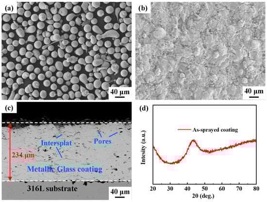
Figure 1.
(a) Fe43Cr20Mo10W4C15B6Y2 (at.%) feedstock powders. (b) Surface morphology of the as-sprayed coating. (c) Backscattered electron image of the cross-section of the as-sprayed coating. (d) XRD pattern of the as-sprayed coating.
The Fe-based metallic glass coating was fabricated using an AcuKote AK-02T HVAF thermal spraying system equipped with an AK7 spraying gun (Kermetico, Benicia, CA, USA). The substrate material was AISI 316L stainless steel. The stainless steel plate was machined and polished to a dimension of 100 mm (length) × 100 mm (width) × 10 mm (thickness). Prior to thermal spraying, the substrate was cleaned with acetone and then grit-blasted to obtain a rough surface, which led to better adhesion between the metallic glass coating and the substrate. Propane was used as the fuel gas in the HVAF process. Metallic glass powder particles were heated and accelerated using a high-velocity flame jet. The Fe-based metallic glass coating was prepared according to the optimized spraying parameters listed in Table 1. Figure 1b displays the as-sprayed Fe-based metallic glass coating, and its microstructure is presented in Figure 1c. The X-ray diffraction (XRD) pattern of the as-sprayed coating is shown in Figure 1d, which reveals that the as-sprayed coating is in the amorphous phase, no crystalline Bragg diffraction peaks can be detected with the resolution of XRD. The thickness and porosity of the as-sprayed coating were 246 ± 5 μm and 1.3 ± 0.1%, respectively. Some defects, such as pores and oxide inclusions, appeared in the as-sprayed coating. In addition, typical in-flatten inter-splats appeared in the coating due to the welding of particles during thermal spraying [40].

Table 1.
Thermal spraying parameters for the HVAF process.
2.2. Nanosecond Pulsed Laser Processing (NPLP)
The schematic diagram of the post-treatment experiment is presented in Figure 2. A CL 500 nanosecond pulsed laser system (Clean-LASER system GmbH, Herzogenrath, Germany) with an output laser wavelength of 1064 nm was used for the NPLP. Gaussian laser pulses with a pulse duration of 110 ns and pulse frequency of 30 kHz were used. A laser optic OSH50 (Clean-LASER system GmbH, Herzogenrath, Germany) was used to focus the laser beam, and a focal laser spot with a 0.7 mm diameter was produced. The movement of the laser optic in the Y-direction was controlled by a KUKA robot (KUKA, Augsburg, Germany). Laser beam scanning was performed with a constant velocity over a 20-mm-wide line in the X-direction at a constant scanning frequency (60–120 Hz).
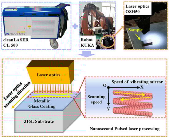
Figure 2.
Nanosecond pulsed laser processing system.
For laser processing, samples with a dimension of 10 mm × 10 mm × 10 mm were wire-cut from the as-sprayed coating. Before laser processing, the samples were preheated to 100 °C for an hour to reduce the effect of thermal stress. High-purity argon gas was used as a protective gas to avoid oxidation. The nanosecond pulsed laser parameters (laser power, scanning frequency, pulse frequency, track spacing, ring spacing) are presented in Table 2. The higher the scanning frequency, the greater the vibrating speed of the scanning mirror. The scanning frequency was set as a unique variable, and the scanning frequencies for the S1–S4 samples were selected as 60 Hz, 80 Hz, 100 Hz, and 120 Hz, respectively. The energy density was calculated as E = P·ts/S, where P, ts, and S represent the laser power (500 W), scanning time (3.3 s, i.e., the moving time of the laser beam in the Y-axis direction), and scanning range (20 mm × 10 mm), respectively.
Table 2.
Nanosecond pulsed laser processing parameters.
2.3. Characterization
The surface and cross-sectional morphologies of the coating samples were examined using a scanning electron microscopy analysis (SEM, Zeiss Sigma VP 300, Oberkochen, Germany). The phase compositions of the specimens were identified by X-ray diffraction (XRD, Rigaku Ultima IV, Matsushihara, Japan) under Cu-Kα radiation at a scanning rate of 5°/min. Transmission electron microscopy (TEM, FEI Strata 400S, Hillsboro, OR, USA) was performed at 200 kV to observe the amorphous microstructure of the remelted layer; the TEM foils were prepared by a focused ion beam (FIB, ZEISS Crossbeam 540, Oberkochen, Germany).
The corrosion behaviors of the coating samples were evaluated by electrochemical measurements using a Gamry Reference 600 electrochemical workstation (Gamry Instruments, Philadelphia, PA, USA). The electrochemical measurements were taken in a standard three-electrode glass cell, where a Pt sheet acted as the counter electrode, saturated calomel electrode (SCE) served as the reference electrode, and each Fe-based metallic glass coating sample worked as the working electrode. The test electrolyte was 3.5 wt.% NaCl solution. Prior to each electrochemical measurement, the sample was potentiostatically reduced at −1 VSCE for 2 min to remove the air-formed oxides on the surface and then kept in a NaCl solution until a stable corrosion potential was achieved. An open-circuit potential (OCP) test was carried out for 30 min before each electrochemical measurement. The electrochemical impedance spectroscopy (EIS) test for each sample was carried out at the OCP with a sinusoidal amplitude of 10 mV in the frequency range of 105–10−2 Hz. Based on the equivalent circuit, impedance plots were interpreted using a suitable fitting procedure in ZsimDemo software (version 3.30). Potentiodynamic polarization tests were performed at room temperature in a voltage range spanning from −0.5 V (SCE) to −1.2 V (SCE) at a scanning rate of 0.333 mV/s.
3. Results
3.1. Surface Morphology and Microstructure
The XRD patterns of the nanosecond pulsed laser-processed Fe-based metallic glass coating samples at different scanning frequencies are presented in Figure 3. The XRD patterns had only one diffused and broad halo peak at 2θ = 40–50°, indicating that the coating maintained a high amorphous phase content after the NPLP.
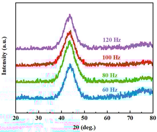
Figure 3.
X-ray diffraction patterns of the laser-processed coating samples with different scanning frequencies (60 Hz, 80 Hz, 100 Hz and 120 Hz).
The surface morphologies of the laser-processed coatings are displayed in Figure 4. A network of cracks and numerous deep cavities were generated on the coating surface, and the homogeneity of the coating surface was improved. These cracks propagated in nearly the same direction, and the spacing between adjacent cracks was 200–300 μm. Deep surface cavities of different sizes appeared due to the gas overflow from the internal pores of the original coating. After NPLP, the coating surface rapidly melted and cooled. Due to the convection and rapid solidification of the molten pool, the gas in the internal pores gathered on the surface to form cavities [41,42].
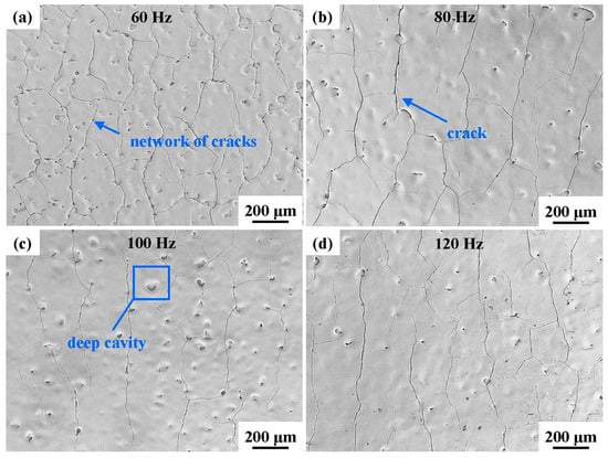
Figure 4.
Surface morphologies of the laser-processed coating samples at different scanning frequencies: (a) 60 Hz; (b) 80 Hz; (c) 100 Hz; and (d) 120 Hz.
With the increase in the scanning frequency from 60 Hz to 120 Hz, the density of cracks and deep cavities on the remelted coating surface decreased. These cracks were mainly generated by large and localized temperature gradients, which caused residual stress during the cooling of the molten pool to room temperature [33,43]. With the increase in the scanning frequency, the number of laser scans per unit time increased and the laser energy distribution on the coating surface became more uniform, reducing the intensities of the thermal gradient and residual stress on the coating surface.
Except for cracks and cavities, the surface structure of all samples was basically the same. The SEM images of the coating surface after NPLP (sample S1) are shown in Figure 5. Numerous uniformly distributed nanoparticles and network structures appeared on the remelted coating surface (Figure 5b,c). Figure 5d,e present the SEM elemental analysis results of these nanoparticles and network structures. It was found that these nanoparticles and network structures were rich in O and Y, and it could be ascribed to the formation of yttrium oxide due to oxidation in the air during laser processing [44].
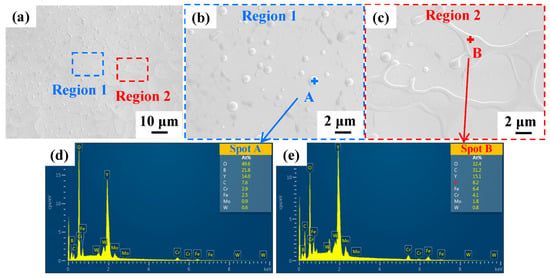
Figure 5.
(a) SEM images of the sample S1 coating surface after NPLP; (b,c) surface structures after magnification; (d,e) EDS analysis results of regions A and B, respectively.
The cross-section morphologies of the laser-processed coating samples are presented in Figure 6. The surface microstructure of the remelted layer of the laser-processed coating was noticeably different from that of the as-sprayed coating. The original inter-splat regions and most of the original pores disappeared in the remelted layer of the as-sprayed coating. Although some transverse micro-cracks and closed pores were formed, the microstructure became denser after laser processing. When the scanning frequency was 60 Hz, the depth of the remelted layer was about 30 μm. The remelting layer depths for the S2, S3, and S4 samples were relatively shallow (15–16 μm).
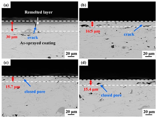
Figure 6.
Cross-sectional morphologies of the laser-processed coating samples at different scanning frequencies: (a) 60 Hz, (b) 80 Hz, (c) 100 Hz, (d) 120 Hz.
To better understand the microstructural evolution in the laser-remelted coating, the TEM bright-field images, selected area electron diffraction (SAED) patterns, and high-resolution transmission electron microscopy (HRTEM) images at a scanning frequency of 60 Hz were captured. For the TEM analysis, a lamellar sample was extracted from the rectangular area marked in Figure 7a using an FIB approach. The bright-field TEM image in Figure 7b reveals no crystalline phases on the coating surface, and the corresponding SAED pattern displays diffused halo rings. The HRTEM image in Figure 7c presents a typical disordered amorphous structure of the remelted layer. It is evident that the remelted layer of the metallic glass coating still maintained its amorphous structure after NPLP.
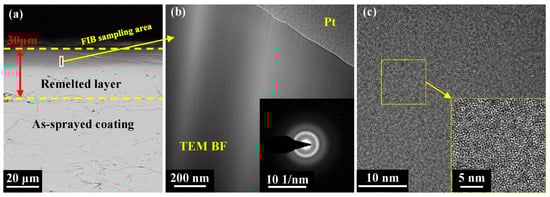
Figure 7.
(a) SEM image and FIB cutting position of the remelted layer; (b) TEM BF images and selected-area diffraction patterns (inset) of the remelted layer; and (c) HRTEM images.
3.2. Corrosion Resistance
Figure 8 exhibits the potentiodynamic polarization curves of the as-sprayed and laser-processed coatings in 3.5 wt.% NaCl solution. An apparent “passivation-like” stage existed in the anode part of each curve due to passive film formation during anodic polarization [45]. The Tafel extrapolation method was adopted to fit these polarization curves, and the corresponding electrochemical parameters (corrosion potential Ecorr, corrosion current density Icorr, passivation current density Ipass, and pitting potential Epit) are listed in Table 3. The Ecorr and Icorr of the as-sprayed coating were −0.55 VSCE and 2.82 × 10⁻⁶ A/cm2, respectively. In comparison to the as-sprayed coating, the electrochemical parameters of the S2, S3, and S4 samples differed very little, except for a slight increase in pitting potential. The Ecorr and Ipass of the S1 sample increased to −0.47 VSCE and decreased to 1.60 × 10⁻³ A/cm2, respectively, due to the denser surface microstructure after laser processing; this indicated that the corrosion resistance of the coating after the laser treatment at 60 Hz was improved. The actual corrosion current density of the laser-processed coating was lower than the measured value. The presence of cracks increased the effective surface area exposed to the electrolyte, improving the apparent current density [3].
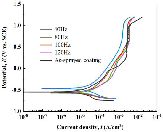
Figure 8.
Potentiodynamic polarization curves of the as-sprayed and laser-remelted metallic glass coatings.
Table 3.
Electrochemical measurement parameters during polarization.
Figure 9 presents the EIS results of the coating samples in 3.5 wt.% NaCl solution. The Nyquist plots in Figure 9a consist of semi-circular arcs with the center of the circle below the X-axis, indicating a charge transfer at the uneven interface [45]. The Bode plots in Figure 9b reveal that low-impedance moduli at lower frequencies were associated with mass diffusion-controlled reaction and that high-impedance moduli at higher frequencies were associated with charge transfer-controlled processes; these associations indicated improved corrosion resistance. The broad peaks of phase angles in the Bode plots displayed the presence of multiple time constants, and the high phase angles at lower frequencies indicated the capacitive nature of oxide layers. The larger the Nyquist plot curvature radius, the stronger the capacitive nature of the laser-processed coating [46].
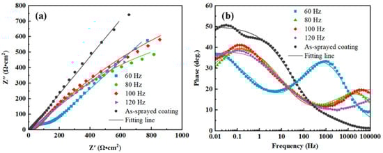
Figure 9.
Electrochemical impedance spectra of the metallic glass coating samples in 3.5 wt.% NaCl solution: (a) Nyquist and (b) Bode plots.
The corresponding equivalent circuits and EIS fitting parameters are presented in Figure 10 and Table 4, respectively. In the equivalent circuits, Rs represents the solution resistance of the corrosive medium, Rct is the charge transfer resistance, Rp is the electrolyte resistance in pores inside the coating, and CPEc represents the constant phase angle component related to coating capacitance (which appeared as a peak in the low-frequency region of the Bode plots). The peak in the high-frequency region was induced by the capacitive arc of the electric double layer capacitor CPEdl. The Rp value of the coating samples was much smaller than their charge transfer resistance (Rct), indicating a dominant effect of charge transfer on coating corrosion behavior. The Rct values of the S2, S3, and S4 samples were lower than that of the as-sprayed coating, implying that the ion transfer process through the electric double layer became much easier due to the presence of cracks. The Rp of the S1 sample increased from 4.09 of the as-sprayed coating to 113.80 Ω·cm−2, whereas its Rct decreased to 9.13 × 10¹¹ Ω·cm−2, which could be attributed to the increase in microstructure density after NPLP [37].
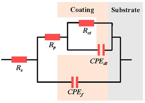
Figure 10.
Equivalent circuit used to fit EIS results.
Table 4.
Electrochemical parameters obtained from EIS spectra of the coating samples.
4. Discussion
The remelted layer formed after NPLP maintained its original amorphous structure. The higher the scanning frequency, the higher the transverse scanning speed. A high transverse scanning speed decreased the input heat of the pulsed laser, resulting in less residence time in the molten state and a higher cooling rate, which facilitated the formation of the amorphous structure [15]. The internal microstructure of the remelted layer of the laser-processed coating became denser than that of the as-sprayed coating, and it could be attributed to the Marangoni flow in the molten pool formed by laser irradiation on the coating surface. Under the irradiation effect of nanosecond pulsed laser, a temperature gradient was generated on the coating surface due to the uneven temperature distribution in the molten pool, resulting in an unequal surface tension. The surface tension gradient drove the non-solidified molten liquid from the low-tension zone to the high-tension zone, causing a height difference in the liquid level. Under the action of gravity, the molten liquid refluxed and caused convection [41,47]. The original pores in the coating flowed over the molten pool surface during the convection process, and a denser remelted layer was obtained after the solidification of the molten pool [48,49].
The microstructure and corrosion resistance of the remelted layer were significantly affected by pulsed laser scanning frequency. When the scanning speed was 3 mm/s, no difference in the laser energy input was noticed in the scanning frequency range of 60–120 Hz; however, the uniformity of energy distribution was different. The uniformity of energy distribution was expressed by the track overlap rate (UT) and the spot overlap rate (US) [50].
where L represents the distance between adjacent pulsed laser tracks and D is the pulsed laser spot diameter. The track overlap rates corresponding to the scanning frequencies of 60 Hz, 80 Hz, 100 Hz, and 120 Hz were 96.4%, 97.3%, 97.9%, and 98.1%, respectively; the corresponding spot overlap rates were 88.9%, 85.2%, 81.5%, and 77.8%, respectively. It is evident from Figure 11 that with the increase in the scanning frequency, the overlap rate of adjacent tracks decreased, and the overlap rate of adjacent pulse points increased. At 60 Hz frequency, the laser energy was more concentrated in a single scanning track, whereas at 120 Hz, the energy was more evenly distributed in the whole laser scanning area. With the increase in the scanning frequency, the convection effect of the molten pool increased, and the surface tension difference decreased. The distribution of the segmented crack network on the coating surface at 120 Hz was more regular and uniform compared with that at 60 Hz [29].
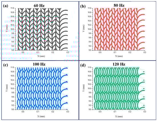
Figure 11.
Pulsed laser spot distributions at different scanning frequencies: (a) 60 Hz, (b) 80 Hz, (c) 100 Hz, (d) 120 Hz.
As the laser energy distribution was more uniform during the NPLP, the temperature gradient on the coating surface during remelting was smaller, and fewer cracks and cavities were generated on the remelted coating surface. The schematic diagram of NPLP of the metallic glass coating samples is displayed in Figure 12. It is observable that most of the inter-splat bonding area disappeared, and the remelted layer became denser due to the Marangoni flow in the molten pool during laser processing [37,41]. Some micro-cracks perpendicular to the coating surface and closed pores were newly formed due to the repeated heating of the material surface by the pulsed laser [51]. As the scanning frequency decreased, adjacent scanning tracks became more dispersed and the laser energy was more concentrated in a single track; thus, the heat accumulation effect increased, and the depth of the remelted layer was larger (30 μm). The temperature gradient that formed between adjacent tracks was more significant, resulting in severe thermal stress and cracks on the coating surface [26,52,53]. At higher scanning frequencies, although the coating surface became more uniform, the remelting depth was only 15 μm, and the remelted layer was less dense. The corrosion resistance of the sample treated at 60 Hz was improved due to the formation of a thicker remelted layer with fewer internal defects. Under all pulsed laser processing parameters, crack networks were generated on the coating surface and greatly impacted its corrosion resistance. An increase in preheating temperature before the NPLP might reduce the thermal stress on the coating surface.
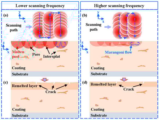
Figure 12.
Schematic diagram of nanosecond pulsed laser progressing: (a) the distribution of pulsed laser spots on the coating surface at lower pulse frequencies; (b) the distribution of pulsed laser spots on the coating surface at higher pulse frequencies; (c) the remelted layer cooled at lower frequencies; and (d) the remelted layer cooled at higher frequencies.
5. Conclusions
In this work, the effects of nanosecond pulsed laser processing on the surface morphology, structural evolution, and corrosion resistance of Fe-based metallic glass coating were systematically analyzed.
After pulsed laser processing, the microstructure of the remelted layer of Fe-based metallic glass coating became more uniform and denser than that of the as-sprayed coating, and the remelted layer retained its amorphous structure. At different scanning frequencies, surface crack networks were generated on the coating surface due to high thermal stress, which deteriorated the corrosion resistance of the remelted layer. At the scanning frequency of 60 Hz, the spot overlap rate of the pulsed laser was larger, resulting in more concentrated laser energy, which led to a thicker remelting layer, denser structure, and better corrosion resistance. At the scanning frequency of 120 Hz, the pulsed laser energy distribution became more uniform, fewer cracks were generated on the coating surface, but the thickness of the remelted layer decreased to 15 μm.
Author Contributions
Conceptualization, X.W. and Z.L.; methodology, X.W.; software, Z.L.; validation, Z.L. and Y.L.; formal analysis, Z.L.; investigation, X.W. and Z.L.; resources, S.W., G.C. and H.L.; data curation, X.W. and Z.L.; writing—original draft preparation, Z.L.; writing—review and editing, X.W.; visualization, X.W. and Z.L.; supervision, M.C. and J.S.; project administration, X.W., S.W. and M.C.; funding acquisition, X.W. All authors have read and agreed to the published version of the manuscript.
Funding
This work was supported by the National Natural Science Foundation of China (Grant no. 51971160).
Data Availability Statement
The raw/processed data required to reproduce the findings reported in this work are available upon request from the corresponding author.
Conflicts of Interest
The authors declare no conflict of interest.
References
- Pang, S.J.; Zhang, T.; Asami, K.; Inoue, A. Synthesis of Fe–Cr–Mo–C–B–P bulk metallic glasses with high corrosion resistance. Acta Mater. 2002, 50, 489–497. [Google Scholar] [CrossRef]
- Inoue, A.; Shen, B.L.; Chang, C.T. Super-high strength of over 4000 MPa for Fe-based bulk glassy alloys in [(Fe1−xCox)0.75B0.2Si0.05]96Nb4 system. Acta Mater. 2004, 52, 4093–4099. [Google Scholar] [CrossRef]
- Bakare, M.; Voisey, K.; Chokethawai, K.; McCartney, D. Corrosion behaviour of crystalline and amorphous forms of the glass forming alloy Fe43Cr16Mo16C15B10. J. Alloys Compd. 2012, 527, 210–218. [Google Scholar] [CrossRef]
- Liang, D.-D.; Wei, X.-S.; Chang, C.-T.; Li, J.-W.; Wang, X.-M.; Shen, J. Effect of W addition on the glass forming ability and mechanical properties of Fe-based metallic glass. J. Alloys Compd. 2018, 731, 1146–1150. [Google Scholar] [CrossRef]
- Li, H.X.; Lu, Z.C.; Wang, S.L.; Wu, Y.; Lu, Z.P. Fe-based bulk metallic glasses: Glass formation, fabrication, properties and applications. Prog. Mater. Sci. 2019, 103, 235–318. [Google Scholar] [CrossRef]
- Lin, T.-J.; Sheu, H.-H.; Lee, C.-Y.; Lee, H.-B. The study of mechanical properties and corrosion behavior of the Fe-based amorphous alloy coatings using high velocity oxygen fuel spraying. J. Alloys Compd. 2021, 867, 159132. [Google Scholar] [CrossRef]
- Wei, X.; Jin, J.; Jiang, Z.; Liang, D.; Shen, J. FeCrMoWCBY metallic glass with high corrosion resistance in molten lead–bismuth eutectic alloy. Corros. Sci. 2021, 190, 109688. [Google Scholar] [CrossRef]
- Li, N.; Pan, J.; Liu, Z.; Liu, L. Metallic glass nanostructures: Forming strategies and functional applications. Mater. Today Adv. 2022, 15, 100253. [Google Scholar] [CrossRef]
- Kumar, A.; Nayak, S.K.; Bijalwan, P.; Dutta, M.; Banerjee, A.; Laha, T. Mechanical and corrosion properties of plasma-sprayed Fe-based amorphous/nanocrystalline composite coating. Adv. Mater. Process. Technol. 2019, 370, 255–268. [Google Scholar] [CrossRef]
- Guo, Y.; Koga, G.Y.; Jorge, A.M.; Savoie, S.; Schulz, R.; Kiminami, C.S.; Bolfarini, C.; Botta, W.J. Microstructural investigation of FeCrNbB amorphous/nanocrystalline coating produced by HVOF. Mater. Des. 2016, 111, 608–615. [Google Scholar] [CrossRef]
- Wang, G.; Huang, Z.; Xiao, P.; Zhu, X. Spraying of Fe-based amorphous coating with high corrosion resistance by HVAF. J. Manuf. Process. 2016, 22, 34–38. [Google Scholar] [CrossRef]
- Huang, B.; Zhang, C.; Zhang, G.; Liao, H. Wear and corrosion resistant performance of thermal-sprayed Fe-based amorphous coatings: A review. Surf. Coat. Technol. 2019, 377, 124896. [Google Scholar] [CrossRef]
- Milanti, A.; Matikainen, V.; Koivuluoto, H.; Bolelli, G.; Lusvarghi, L.; Vuoristo, P. Effect of spraying parameters on the microstructural and corrosion properties of HVAF-sprayed Fe–Cr–Ni–B–C coatings. Surf. Coat. Technol. 2015, 277, 81–90. [Google Scholar] [CrossRef]
- Bijalwan, P.; Kumar, A.; Nayak, S.K.; Banerjee, A.; Dutta, M.; Laha, T. Microstructure and corrosion behavior of Fe-based amorphous composite coatings developed by atmospheric plasma spraying. J. Alloys Compd. 2019, 796, 47–54. [Google Scholar] [CrossRef]
- Chen, H.; Kong, D. Effects of laser remelting speeds on microstructure, immersion corrosion, and electrochemical corrosion of arc–sprayed amorphous Al–Ti–Ni coatings. J. Alloys Compd. 2019, 771, 584–594. [Google Scholar] [CrossRef]
- Jiang, C.; Lu, J.; Liu, W.; Xing, Y.; Zhang, F.; Chen, Y. Corrosion resistance of plasma-sprayed Fe-based coatings by using core-shell structure powders. J. Mater. Res. Technol. 2020, 9, 12273–12280. [Google Scholar] [CrossRef]
- Chen, S.-Y.; Ma, G.-Z.; Wang, H.-D.; He, P.-F.; Liu, Z. Solidification mechanism and quantitative characterization of Fe-based amorphous splat formed by plasma sprayed droplets with different in-flight status. J. Alloys Compd. 2018, 768, 789–799. [Google Scholar] [CrossRef]
- Jiang, H.-R.; Li, M.-L.; Wei, X.-S.; Ma, T.-C.; Dong, Y.; Ying, C.-X.; Liao, Z.-Y.; Shen, J. Numerical Investigation of In-Flight Behavior of Fe-Based Amorphous Alloy Particles in AC-HVAF Thermal Spray Process. J. Therm. Spray Technol. 2019, 28, 1146–1159. [Google Scholar] [CrossRef]
- Ma, G.Z.; Chen, S.Y.; He, P.F.; Wang, H.D.; Zhou, Y.Y.; Zhao, Q.; Li, G.L. Particle in-flight status and its influence on the properties of supersonic plasma-sprayed Fe-based amorphous metallic coatings. Surf. Coat. Technol. 2019, 358, 394–403. [Google Scholar]
- Yang, Y.; Zhang, C.; Peng, Y.; Yu, Y.; Liu, L. Effects of crystallization on the corrosion resistance of Fe-based amorphous coatings. Corros. Sci. 2012, 59, 10–19. [Google Scholar] [CrossRef]
- Wang, Y.; Li, M.; Zhu, F.; Dong, W.; Zhang, X.; Sun, L. Pitting corrosion mechanism of Cl−- and S2−-induced by oxide inclusions in Fe-based amorphous metallic coatings. Surf. Coat. Technol. 2020, 385, 125449. [Google Scholar] [CrossRef]
- Zhang, S.; Wu, J.; Qi, W.; Wang, J. Effect of porosity defects on the long-term corrosion behaviour of Fe-based amorphous alloy coated mild steel. Corros. Sci. 2016, 110, 57–70. [Google Scholar] [CrossRef]
- Fu, B.-Y.; He, D.-Y.; Zhao, L.-D. Effect of heat treatment on the microstructure and mechanical properties of Fe-based amorphous coatings. J. Alloys Compd. 2009, 480, 422–427. [Google Scholar] [CrossRef]
- Jiao, J.; Luo, Q.; Wei, X.; Wang, Y.; Shen, J. Influence of sealing treatment on the corrosion resistance of Fe-based amorphous coatings in HCl solution. J. Alloys Compd. 2017, 714, 356–362. [Google Scholar] [CrossRef]
- Wang, Q.-Y.; Xi, Y.-C.; Zhao, Y.-H.; Liu, S.; Bai, S.-L.; Liu, Z.-D. Effects of laser re-melting and annealing on microstructure, mechanical property and corrosion resistance of Fe-based amorphous/crystalline composite coating. Mater. Charact. 2017, 127, 239–247. [Google Scholar] [CrossRef]
- Wang, H.-Z.; Cheng, Y.-H.; Yang, J.-Y.; Wang, Q.-Q. Wang, Influence of laser remelting on organization, mechanical properties and corrosion resistance of Fe-based amorphous composite coating. Surf. Coat. Technol. 2021, 414, 127081. [Google Scholar] [CrossRef]
- Zhang, J.; Yu, M.; Li, Z.; Liu, Y.; Zhang, Q.; Jiang, R.; Sun, S. The effect of laser energy density on the microstructure, residual stress and phase composition of H13 steel treated by laser surface melting. J. Alloys Compd. 2021, 856, 158168. [Google Scholar] [CrossRef]
- Zhu, L.; Xue, P.; Lan, Q.; Meng, G.; Ren, Y.; Yang, Z.; Xu, P.; Liu, Z. Recent research and development status of laser cladding: A review. Opt. Laser Technol. 2021, 138, 106915. [Google Scholar] [CrossRef]
- Fan, Z.; Wang, K.; Dong, X.; Wang, R.; Duan, W.; Mei, X.; Wang, W.; Cui, J.; Zhang, S.; Xu, C. The role of the surface morphology and segmented cracks on the damage forms of laser re-melted thermal barrier coatings in presence of a molten salt (Na2SO4+V2O5). Corros. Sci. 2017, 115, 56–67. [Google Scholar] [CrossRef]
- Das, B.; Nath, A.; Bandyopadhyay, P. Scratch resistance and damage mechanism of laser remelted thermally sprayed ceramic coating. Surf. Coat. Technol. 2019, 364, 157–169. [Google Scholar] [CrossRef]
- Zhang, Y.; Gao, X.; Liang, X.; Chong, K.; Wu, D.; Zou, Y. Effect of laser remelting on the microstructure and corrosion property of the arc-sprayed AlFeNbNi coatings. Surf. Coat. Technol. 2020, 398, 126099. [Google Scholar] [CrossRef]
- Nayak, S.K.; Kumar, A.; Sarkar, K.; Banerjee, A.; Laha, T. Mechanistic insight into the role of amorphicity and porosity on determining the corrosion mitigation behavior of Fe-based amorphous/nanocrystalline coating. J. Alloys Compd. 2020, 849, 156624. [Google Scholar] [CrossRef]
- Smurov, I.; Uglov, A.; Krivonogov, Y.; Sturlese, S.; Bartuli, C. Pulsed laser treatment of plasma-sprayed thermal barrier coatings: Effect of pulse duration and energy input. J. Mater. Sci. 1992, 27, 4523–4530. [Google Scholar] [CrossRef]
- Tariq, N.; Hasan, B.; Akhter, J. Evolution of microstructure in Zr55Cu30Al10Ni5 bulk amorphous alloy by high power pulsed Nd:YAG laser. J. Alloys Compd. 2009, 485, 212–214. [Google Scholar] [CrossRef]
- Richter, B.; Chen, S.; Morrow, J.D.; Sridharan, K.; Eriten, M.; Pfefferkorn, F.E. Pulsed laser remelting of A384 aluminum, part II: Modeling of surface homogenization and topographical effects. J. Manuf. Process. 2018, 32, 230–240. [Google Scholar] [CrossRef]
- Mustafa, H.; Matthews, D.T.A.; Römer, G.R.B.E. Investigation of the ultrashort pulsed laser processing of zinc at 515 nm: Morphology, crystallography and ablation threshold. Mater. Des. 2019, 169, 107675. [Google Scholar] [CrossRef]
- Chong, K.; Zou, Y.; Wu, D.; Tang, Y.; Zhang, Y. Pulsed laser remelting supersonic plasma sprayed Cr3C2-NiCr coatings for regulating microstructure, hardness and corrosion properties. Surf. Coat. Technol. 2021, 418, 127258. [Google Scholar] [CrossRef]
- Qian, Y.; Huang, H.; Wang, C.; Yu, P.; Xu, J.; Zhang, Z. Formation of leaf-shaped microstructure on Zr-based metallic glass via nanosecond pulsed laser irradiation. J. Manuf. Process. 2021, 72, 61–70. [Google Scholar] [CrossRef]
- Guo, L.; Geng, S.; Pang, J.; Hu, Y.; Lan, S.; Wang, C.; Wang, W. Structural transformation and property improvement of Fe78Si9B13 amorphous ribbon by pulsed laser processing. Mater. Des. 2018, 160, 538–548. [Google Scholar] [CrossRef]
- Wang, W.; Zhang, C.; Xu, P.; Yasir, M.; Liu, L. Enhancement of oxidation and wear resistance of Fe-based amorphous coatings by surface modification of feedstock powders. Mater. Des. 2015, 73, 35–41. [Google Scholar] [CrossRef]
- Triantafyllidis, D.; Li, L.; Stott, F. Mechanisms of porosity formation along the solid/liquid interface during laser melting of ceramics. Appl. Surf. Sci. 2003, 208–209, 458–462. [Google Scholar] [CrossRef]
- Shi, T.; Wang, C.; Mi, G.; Yan, F. A study of microstructure and mechanical properties of aluminum alloy using laser cleaning. J. Manuf. Process. 2019, 42, 60–66. [Google Scholar] [CrossRef]
- Batista, C.; Portinha, A.; Ribeiro, R.; Teixeira, V.; Costa, M.; Oliveira, C. Morphological and microstructural characterization of laser-glazed plasma-sprayed thermal barrier coatings. Surf. Coat. Technol. 2006, 200, 2929–2937. [Google Scholar] [CrossRef]
- Qian, Y.; Huang, H.; Jiang, M.; Yan, J. Nanosecond pulsed laser-induced formation of nanopattern on Fe-based metallic glass surface. Appl. Surf. Sci. 2022, 577, 151976. [Google Scholar] [CrossRef]
- Bommersbach, P.; Alemany-Dumont, C.; Millet, J.; Normand, B. Formation and behaviour study of an environment-friendly corrosion inhibitor by electrochemical methods. Electrochim. Acta 2005, 51, 1076–1084. [Google Scholar] [CrossRef]
- Cui, S.; Zhai, H.; Li, W.; Fan, X.; Li, X.; Ning, W.; Xiong, D. Microstructure and corrosion resistance of Fe-based amorphous coating prepared by detonation spray. Surf. Coat. Technol. 2020, 399, 126096. [Google Scholar] [CrossRef]
- Temmler, A.; Pirch, N.; Luo, J.; Schleifenbaum, J.H.; Häfner, C.L. Numerical and experimental investigation on formation of surface structures in laser remelting for additive-manufactured Inconel 718. Surf. Coat. Technol. 2020, 403, 126370. [Google Scholar] [CrossRef]
- Zhao, H.; Niu, W.; Zhang, B.; Lei, Y.; Kodama, M.; Ishide, T. Modelling of keyhole dynamics and porosity formation considering the adaptive keyhole shape and three-phase coupling during deep-penetration laser welding. J. Phys. D Appl. Phys. 2011, 44, 485302. [Google Scholar] [CrossRef]
- Kovalev, O.; Gurin, A. Multivortex convection of metal in molten pool with dispersed impurity induced by laser radiation. Int. J. Heat Mass Transf. 2014, 68, 269–277. [Google Scholar] [CrossRef]
- Zhu, L.; Gao, Q.; Sun, B.; Ke, Y.; Tan, Y.; Cao, Y. Nanosecond laser cleaning for enhanced zinc coating quality of HSLA steel. Opt. Laser Technol. 2021, 143, 107311. [Google Scholar] [CrossRef]
- Grabowski, A.; Florian, T.; Wieczorek, J.; Adamiak, M. Structuring of the Ti6Al4V alloy surface by pulsed laser remelting. Appl. Surf. Sci. 2021, 535, 147618. [Google Scholar] [CrossRef]
- Ouyang, D.; Li, N.; Xing, W.; Zhang, J.; Liu, L. 3D printing of crack-free high strength Zr-based bulk metallic glass composite by selective laser melting. Intermetallics 2017, 90, 128–134. [Google Scholar] [CrossRef]
- Hu, C.; He, G.; Chen, J.; Fang, Z.; Yang, Z.; Zhang, Z. Research on Cleaning Mechanism of Anti-Erosion Coating Based on Thermal and Force Effects of Laser Shock. Coatings 2020, 10, 683. [Google Scholar] [CrossRef]


Publisher’s Note: MDPI stays neutral with regard to jurisdictional claims in published maps and institutional affiliations. |
© 2022 by the authors. Licensee MDPI, Basel, Switzerland. This article is an open access article distributed under the terms and conditions of the Creative Commons Attribution (CC BY) license (https://creativecommons.org/licenses/by/4.0/).