Abstract
Interest in hydrogen energy is increasing due to its eco-friendliness and ease of use. Research is being conducted to produce and use hydrogen in various fields such as hydrogen vehicles and nuclear power plants. However, considering the purity requirements and the need for containment, experiments with hydrogen have several constraints, such as accounting for the charging and purging time. In this study, the effects of hydrogen gas on the fracture properties of T6 heat-treated 6061 aluminum alloy (Al6061-T6) and Chromium-molybdenum steel (SA372) were investigated using the extended finite element method (XFEM). First, numerical analyses for smooth and notched slow strain rate tensile test specimens under air and hydrogen gas conditions were conducted using a multi-island genetic algorithm and XFEM to derive true stress–strain data and damage parameters of the two materials based on experimental results. Second, the fracture resistance curves of ½T-compact tension (CT) specimens made of SA372 steel were determined by crack growth analyses using the calibrated parameters. The estimated JQ values were compared with those from experiments to validate the method, of which differences were less than 20%. Finally, the fracture properties of Al6061-T6 alloy were predicted using the same method with ½T-CT specimens.
1. Introduction
Recently, interest in hydrogen as a next-generation energy source has increased, owing to its low cost, eco-friendliness, and abundance. Consequently, efforts have also been made to safely produce, store, and transport hydrogen. For instance, a very high-temperature gas-cooled generation-IV reactor was developed to produce hydrogen via thermochemical processes. Additionally, type I–IV tanks have been manufactured and researched for the storage and transport of hydrogen. In the presence of hydrogen, metallic materials undergo degradation, which is known as hydrogen embrittlement. This can furthermore lead to the leakage of hydrogen gas and can cause catastrophic accidents such as chain explosions. In fact, hydrogen-gas chain explosions have occurred in several countries and have caused damage to property as well as casualties. Therefore, the fitness for service assessment of metallic materials under hydrogen gas conditions should be conducted to prevent unanticipated accidents due to changes in material properties.
Although much research is being conducted to reveal the mechanism of hydrogen-gas-induced degradation, the definitive mechanism still is not clear. That said, it is believed that since hydrogen atoms are small, they can easily penetrate through the relatively large openings in a metallic lattice and recombine with other hydrogen atoms in the metal [1]. This can deteriorate the mechanical properties of the metal and is known as hydrogen embrittlement (HE). Safyari et al. [2] assessed the HE effect in Al-Cu-Mg alloy via microstructure investigations considering the hydrogen trap site and its binding energy. As a result, in a cold-rolled specimen, hydrogen-assisted crack nucleation along the grain boundaries was determined as dominant effect. Additionally, resistance against the HE, as well as the effects of retention and mobility of precipitation, were discussed. Subsequently, they examined the microstructural behavior of hydrogen in 7xxx series aluminum alloys [3]. Specific features of hydrogen trapping and embrittlement were evaluated by the experimental procedure.
Matsuoka et al. [4] conducted slow strain rate tensile (SSRT), fracture toughness, fatigue crack growth, and fatigue life tests of smooth cylindrical stainless steel bars with stresses ranging from 78 to 115 MPa and temperatures ranging from −40 °C to room temperature in the presence of hydrogen. They also investigated the pressure and temperature effect of hydrogen gas on stainless steels. Nguyen et al. [5,6] performed SSRT tests for smooth and notched cylindrical specimens and fracture toughness tests for American petroleum institute’s (API)-X70 steel under 10 MPa and room temperature conditions with varying amounts of hydrogen gas. Additionally, experiments for Cr-Mo steel under air and hydrogen conditions were conducted. Based on this research, the amount of crack tip openings were determined as a function of the amount of hydrogen gas. Zhou et al. [7] performed experiments for X80 steel under simulated hydrogen-blended natural gas conditions. The amount of change in tensile strength, elongation after fracture and reduction of area is significantly large in notched specimens than in smooth specimens with the increase of hydrogen contents. Guy et al. [8] investigated the HE phenomenon and its effect on the design and maintenance of transportation pipes. The assessment of the pipe defect was carried out by using several methods and recommended the failure assessment diagram (FAD) as the promising one. Anyway, experiments involving metals and hydrogen gas are difficult and have many constraints. In particular, sealing, separated containment, and ventilation must be considered to prevent severe accidents such as explosions.
Alternately, several theoretical models and simulation techniques have been developed to study the discontinuities in structures. The virtual crack closure technique, cohesive zone model, and intra-element method were introduced to solve traditional finite element method problems such as expensive re-meshing processes and high element density. Additionally, damage models such as the Gurson–Tvergaard–Needlemen (GTN) and Rousselier models have been developed and widely used. Sérgio et al. [9] investigated the sensitivity of the GTN parameters for T351-treated 2024 aluminum alloy (Al2024-T351) steel. However, the aforementioned models require considerable effort to calibrate the damage parameters. The simulation of discontinuities using the extended finite-element method (XFEM) was developed in 1999 by Belytschko et al. [10] to overcome the limitations of previous methods. The elements used in XFEM are endowed with additional degrees of freedom that allow the simulation of discontinuities. Unlike other methods, XFEM does not require focused meshing for crack initiation and propagation analyses or stationary crack analysis while calculating the fracture parameters such as stress intensity factor and J-integral. In particular, crack initiation and propagation were simulated using phantom nodes and relatively few damage parameters. Fageehi [11] conducted fatigue crack growth analyses for cold-rolled Society of Automotive Engineers (SAE) 1020 and T6-treated 7075 aluminum alloy (Al7075-T6) steels using XFEM and compared the results with experimental results. Kim et al. [12] verified XFEM for marine steel (SM) 490A and investigated the effects of hydrogen on API-X70 steel.
The optimization of the damage parameters is essential for determining the accuracy of the interpretation. Gradient-based, pattern-based, and exploratory technique optimization algorithms have been developed and used in many areas, such as aircraft and ships [13]. Gradient-based algorithms have the lowest computational cost, and pattern-based algorithms, such as the Hooke–Jeeves technique, are suitable for both continuous and discrete problems. However, since the above algorithms depend on the initial design point, local optimization may occur. On the other hand, exploratory algorithms, such as the multi-island genetic algorithm (MIGA), do not depend on the initial design point and, hence, global optimization is possible with it. Pyo et al. [14] evaluated the parameters of a heat source model for gas metal arc welding using MIGA.
The purpose of this research is to quantify experimentally how the fracture properties of typical materials used in hydrogen tanks change according to the presence or absence of hydrogen, and to address mainly an alternative numerical analysis method with calibrated damage parameters that can replace the expensive and time-consuming fracture tests. In this context, the effects of hydrogen gas on the fracture properties of T6 heat-treated 6061 aluminum alloy (Al6061-T6) and Chromium–molybdenum steel (SA372) were evaluated using XFEM in ABAQUS [15]. First, numerical analyses for smooth and notched slow-strain tensile test specimens of the two materials were conducted and compared with experimental data to derive the true stress–strain data and damage parameters using MIGA in Isight [16] and XFEM. Second, the determined data were used for ½T-compact tension (CT) specimens made of SA372 steel and the estimated JQ values were compared with those from experiments to validate the method. Finally, the fracture properties of Al6061-T6 alloy were predicted using the same method.
2. Method of Experiments and Analyses
2.1. Experimental Procedure
Experiments were performed at the Korea Research Institute of Standards and Science. A separate experimental building with ventilation was constructed to ensure that the experiments were conducted in a hydrogen-safe environment. A hydrogen gas pipeline to an autoclave was designed to withstand gas pressures up to 250 MPa. Moreover, the autoclave was designed to withstand pressures of up to 120 MPa. The experiments were performed according to the ASTM G142 standard [17]. Experiments were repeated three or more times for all conditions and specimens, and the median value was used for the analysis. Before the experiment, the pipeline and autoclave were vacuumed to 30 Pa and filled with 10 MPa nitrogen gas to completely remove any remaining gas in them. The filled nitrogen gas was subsequently released, and the process was repeated four times. The purging of the testing gas up to 10 MPa was repeated three times to ensure purity. After purging, the testing gas was charged in the autoclave at the corresponding pressure and maintained for at least 30 min to check its pressure-holding capability. After the experiment, the testing gas in the pipeline and autoclave was released at an appropriate rate depending on the pressure and temperature.
The representative candidate materials for hydrogen tanks are SA372 steel and Al6061-T6 alloy. The former material has a high yield and ultimate tensile strength, and its ductility reduces significantly under the hydrogen gas condition. However, the latter material has a low yield and ultimate tensile strength, and its ductility is insensitive to the presence or absence of hydrogen. With regard to the aluminum alloy, although the thin oxide layer on the specimen may affect surface reactions of hydrogen, it seems that the pre-exposure time during pressure stabilization after hydrogen pressurization could have been sufficient for the hydrogen to diffuse and interact with the metal lattice, resulting in negligible degradation [6].
The SSRT specimens were machined along the circumferential direction of the tank body, which was expected to have the highest load. Smooth and notched cylindrical specimens were manufactured following the ASTM E8 standard [18]. The crosshead speeds for the smooth and notched cylindrical specimens determined according to the ASTM G129 standard [19] were 0.002 mm/s and 0.02 mm/s, respectively. The loads and strains were measured using a load cell and clip-on extensometer.
The ½T-CT specimens were machined at the same location as that of the SSRT specimens. The in-plane of the specimens was manufactured with a 1T standard specimen size, whereas the thickness of the specimens was ½T owing to the size of the tank. The specimens were pre-cracked by fatigue loading with a loading ratio of R = 0.1 and a frequency of 10 Hz. The size of the pre-crack was 3 mm, which corresponded to a0/W = 0.46. Side grooves with 10% thickness were machined on each side to create a plane-strain condition. The experiments were conducted according to the ASTM 1820 standard [20]. The load-line displacements were measured using a clip gauge at a rate of 1 mm/min. The final crack sizes were determined by averaging nine points based on the standard.
2.2. XFEM and Multi-Island Genetic Algorithm
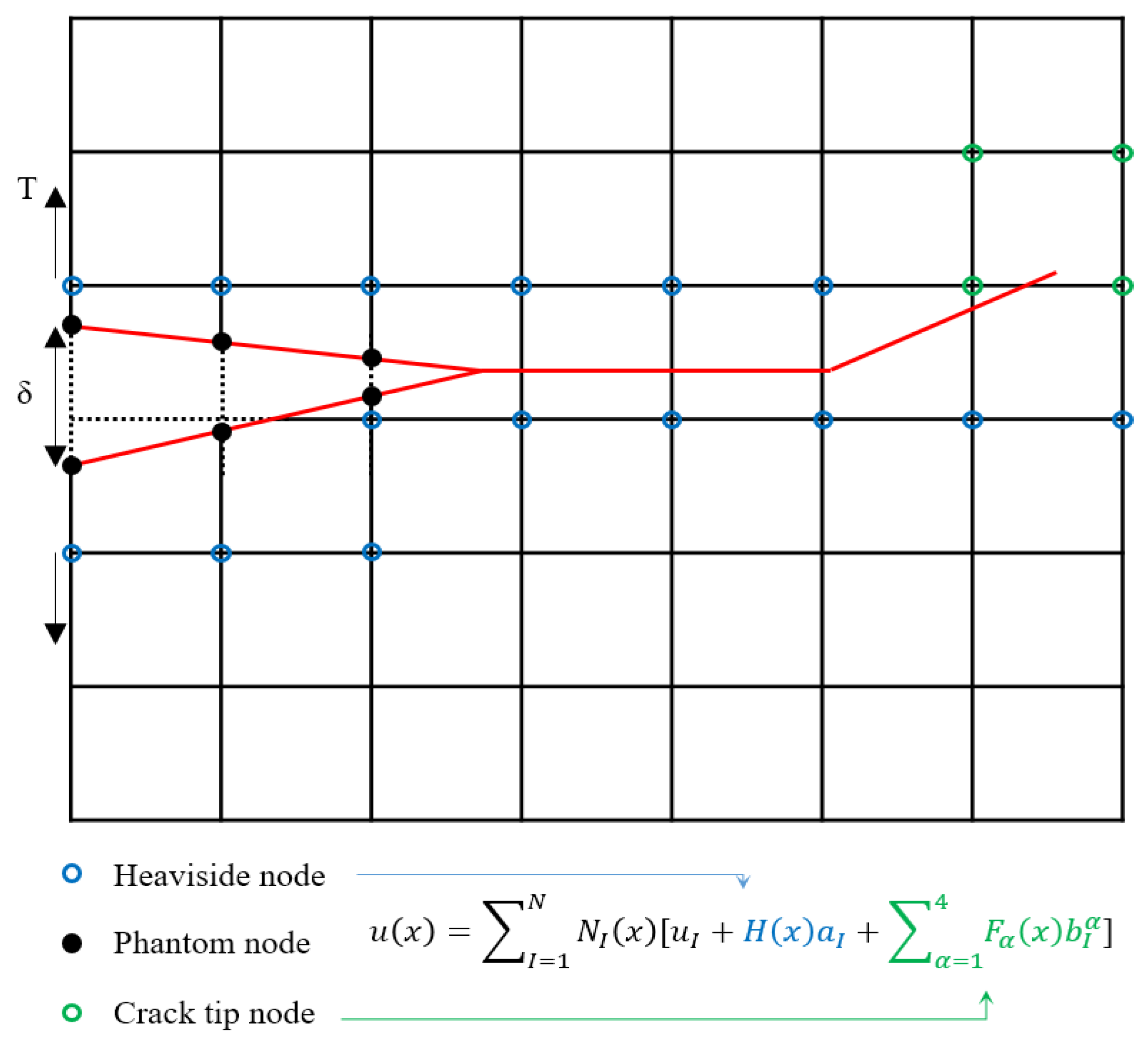
A schematic of the XFEM with displacement approximation is shown in Figure 1. Compared to the conventional finite element method, Heaviside and crack-tip functions were added for the XFEM. Crack initiation and propagation were simulated using an XFEM-based cohesive segment governed by the traction–separation law. Two of the three parameters, namely, cohesive strength, cohesive energy, and critical displacement, are required to simulate crack initiation and propagation using the linear traction–separation law. Damage evolution can be studied using one of the six criteria: maximum principal stress (MAXPS), maximum principal strain (MAXPE), maximum nominal stress (MAXS), maximum nominal strain (MAXE), quadratic nominal stress (QUADS), and quadratic nominal strain (QUADE). Among these, MAXPS is commonly used to simulate crack growth [21,22,23,24]. Phantom nodes are generated when the MAXPS of the elements equals the cohesive strength (). The distance between the phantom nodes increases with an increase in the force, and fracture is considered to have occurred when the distance exceeded the critical separation (). The cohesive damage ( was determined by the linear relationship between cohesive strength and critical separation as = .
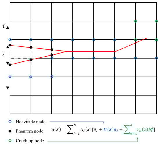
Figure 1.
Schematic of XFEM.
The traditional genetic algorithm (TGA), an optimization method proposed by Holland in the 1960s based on biological evolution and genetics [25], was first applied to structures by Goldberg [26]. Because genetic algorithms do not use derivative terms, the convergence of the solution is guaranteed. Additionally, it has low dependence on the initial design point and results in local optimization too. The MIGA is an advancement over TGA wherein each generation is divided into islands. In it, selection, crossover, and mutation are conducted for each island. In the present study, individuals from each island were selected and migrated to other islands following the roulette selection method. Migration was controlled by the rate and interval. Figure 2 shows a schematic of the MIGA flow [14].
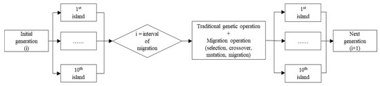
Figure 2.
Schematic of MIGA [14].
2.3. Analysis procedure
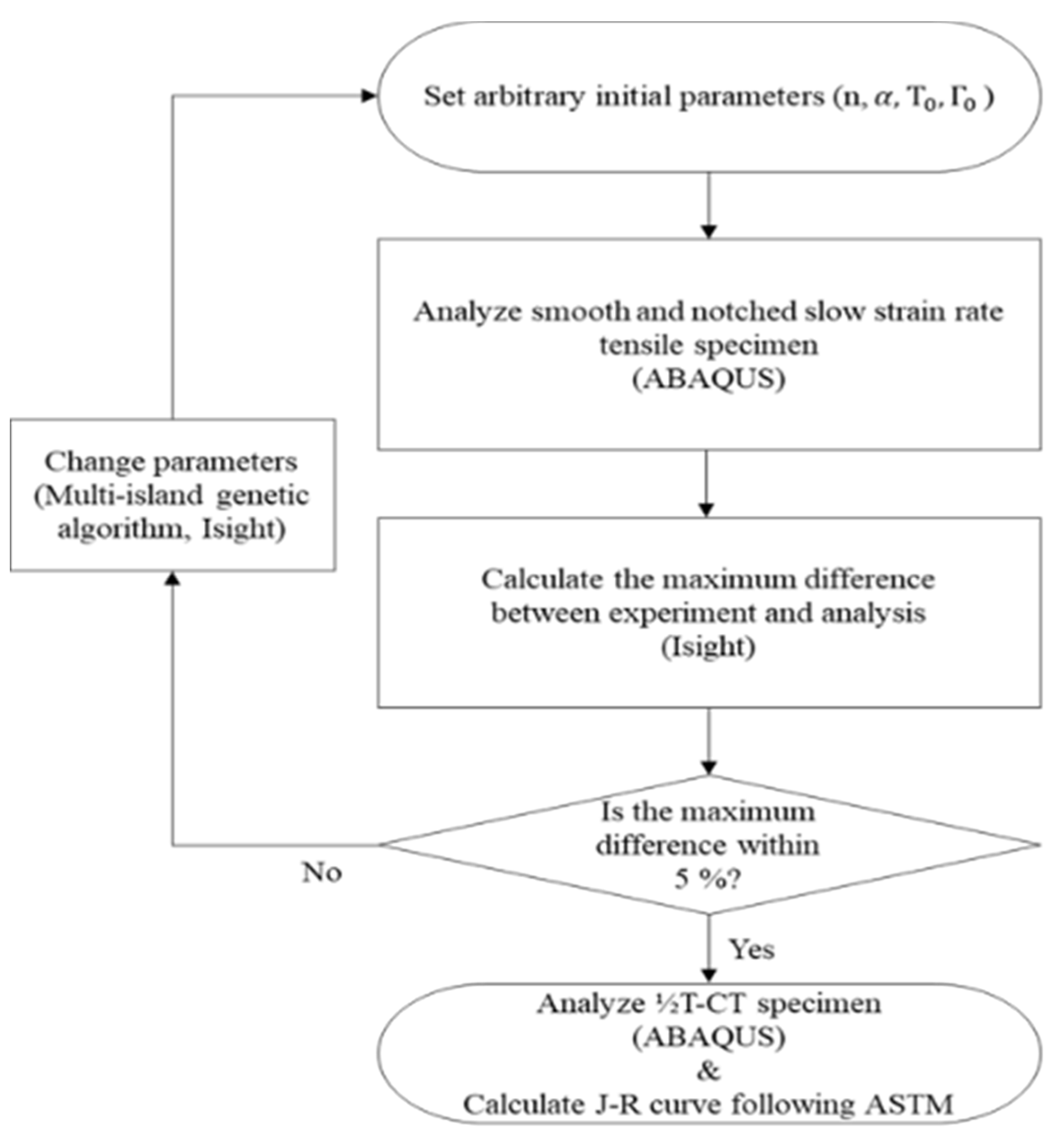
A specific flowchart describing the analysis process considered in this study is shown in Figure 3. Arbitrary parameters, such as Ramberg–Osgood (n, ) and damage (, ) parameters, were set for the smooth and notched cylindrical specimens. The SSRT specimens were analyzed using this method and the maximum difference between the experiment and analysis was calculated. If the maximum difference was within 5%, the determined parameters were used to analyze the ½T-CT specimen. However, if the maximum difference was greater than 5%, the parameters were changed using MIGA. The optimization parameters for the MIGA are listed in Table 1. This procedure was repeated, depending on the materials and conditions used. The JQ values estimated for SA372 steel were compared with the experimental results to verify the method. The fracture properties of Al6061-T6 alloy were then predicted using the same method with ½T-CT specimens.
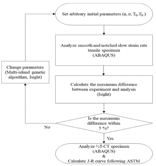
Figure 3.
Flow chart showing the analysis procedure.

Table 1.
Optimization parameters of MIGA.
3. Evaluation of Slow Strain Rate Tensile Specimen
3.1. Analysis Models and Conditions
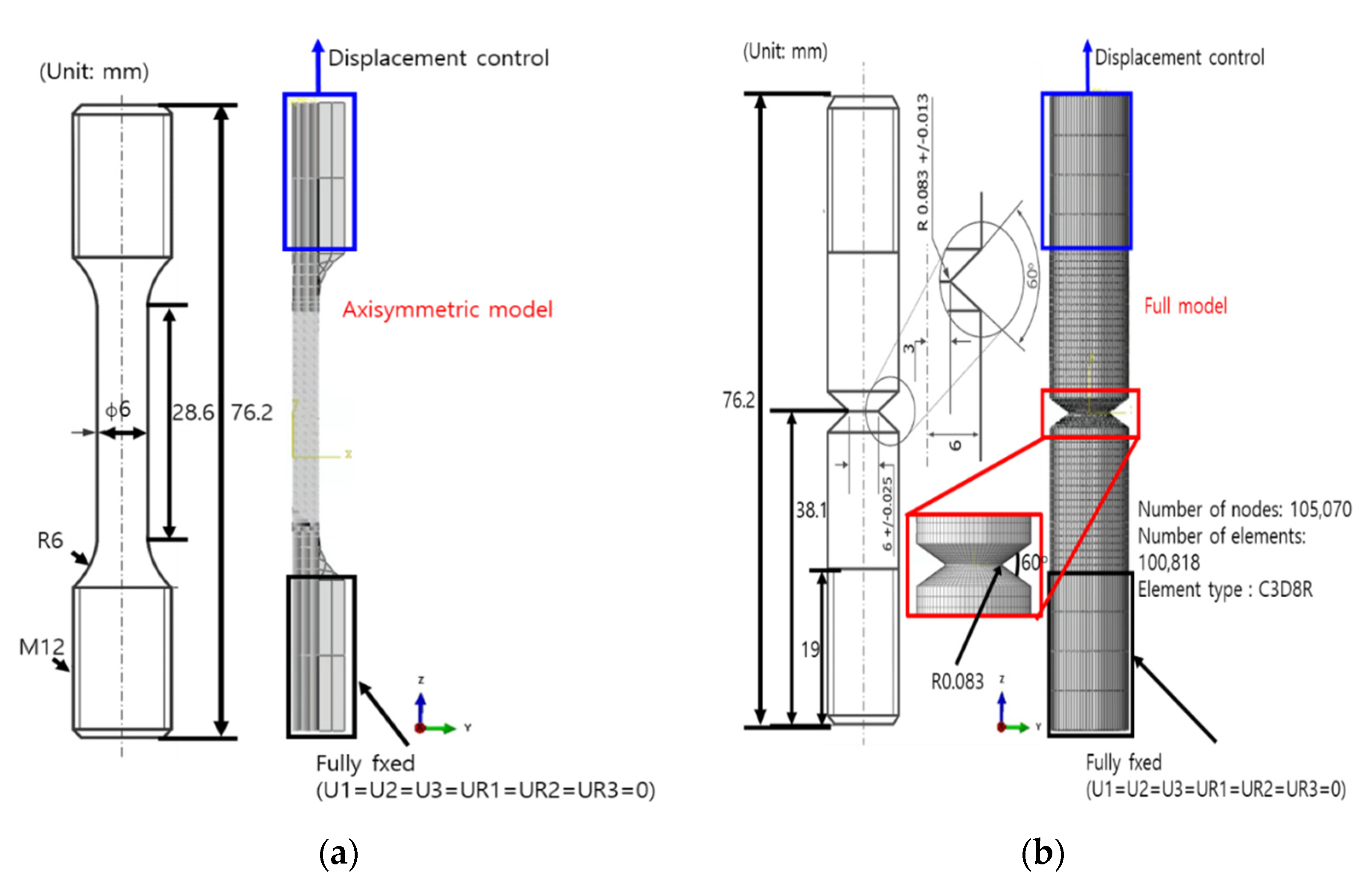
The chemical compositions are listed in Table 2 and mechanical properties determined from three tensile tests for each material are summarized in Table 3. Figure 4 shows schematics and the FE model of SSRT specimens. Both the FE models shown in the figure were used to simulate behaviors of Al6061-T6 alloy and SA372 steel in the presence of noble and hydrogen gases. The smooth cylindrical specimen was modeled using an axisymmetric option to reduce the analysis time. The axisymmetric model consisted of 31,741 nodes and 31,164 continuum 4-node axisymmetric solid elements with reduced integration (CAX4R) and continuum 3-node axisymmetric solid elements (CAX3). The overall specimen length was 76.2 mm and the gauge length was 28.6 mm. The net section diameter was 6 mm and the grip section diameter was 12 mm. A strain gauge was attached at a distance of 25 mm. On the other hand, a 3-dimensional model with 105,070 nodes and 100,818 continuum 3-dimensional 8-node elements with reduced integration (C3D8R) was used for the notched cylindrical specimen. The overall length was the same as that of the smooth cylindrical specimen. The notch section diameter was 6 mm and the grip section diameter was 12 mm. The notch angle and radius were 60° and 0.083 mm, respectively.
Table 2.
Chemical compositions of Al6061-T6 alloy and SA372 steel.
Table 3.
Mechanical properties of Al6061-T6 alloy and SA372 steel.

Figure 4.
Schematics and FE models of the (a) smooth and (b) notched cylindrical SSRT specimens.
The bottom grip section of the SSRT specimens was fixed in all directions, and the top grip section was displaced vertically during the simulation. Moreover, the crosshead speeds obtained from the experiments were used for the static analyses. Analyses of the smooth cylindrical specimens were performed without XFEM to reduce the computational time, while the XFEM was used to analyze the notched cylindrical specimens. Additionally, the analyses were repeated by changing the parameters using MIGA until the maximum difference was within 5%. The damage parameters determined are listed in Table 4.
Table 4.
Damage parameters of Al6061-T6 alloy and SA372 steel.
3.2. Analysis Results and Discussion
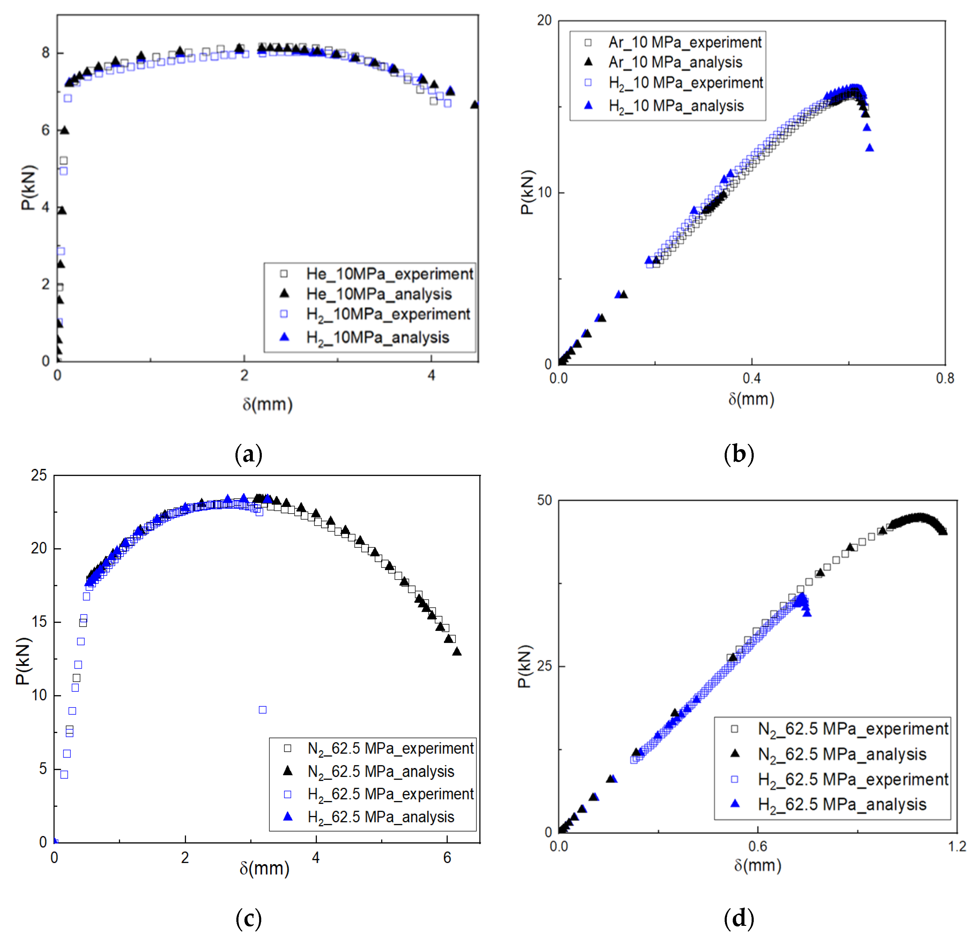
Figure 5 shows the load–displacement curves of the experiments and analyses for the SSRT specimens under these two conditions. Because XFEM was not used for the smooth cylindrical specimen, the load was compared with that in the experiments. The maximum difference in the load until the ultimate tensile strength was used as a criterion to calibrate the true stress–strain data. For the notched cylindrical specimen simulated using XFEM, the total displacement until fracture was instead compared with the experiments.
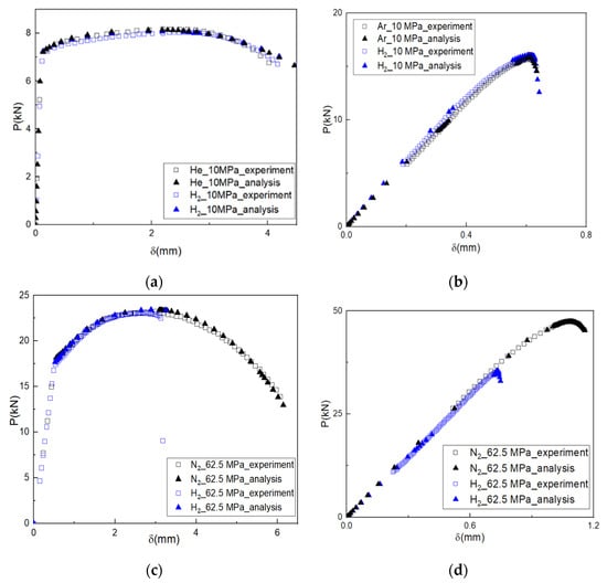
Figure 5.
Load–displacement curves of (a) smooth; and (b) notched cylindrical specimens made of Al6061-T6 alloy, and of (c) smooth; and (d) notched cylindrical specimens made of SA372 steel.
The maximum load differences for the smooth cylindrical specimens made of SA372 steel were 0.3 kN at a displacement of 3.09 mm and 0.33 kN at a displacement of 2.65 mm under 62.5 MPa noble and hydrogen gas pressures, respectively. The total displacements for the notched cylindrical specimen were the same as 0.01 mm for the above two conditions. The maximum differences between the experiment and analysis results were 0.85% and 1.34%, respectively. In contrast, the maximum load differences in the Al6061-T6 alloy were 0.37 kN at a displacement of 0.01 mm and 0.26 kN at a displacement of 0.13 mm under 10 MPa noble and hydrogen gas pressures. The total displacements were 0.003 and 0.1 mm, for these two conditions, and the maximum differences were 4.51% and 3.22%, respectively.
Degradation in the mechanical and fracture properties of SA372 steel may be explained in terms of ductility because the presence of severe deformation during necking can induce more hydrogen absorption and provide more hydrogen trapping in the metal lattice. However, since not only were the tensile strengths unchanged but also there was no obvious necking of the hydrogen-exposed specimens in Al6061-T6 alloy, fracture properties were not changed remarkably. Typical microstructures of this material comprised tempered bainite and martensite with different-sized inclusions inside the grains, which characteristics can be found in the author’s previous work [6].
Meanwhile, because the maximum difference criteria depicted in Figure 3 for both the smooth and notched cylindrical specimens were satisfied for two types of materials and for a variety of conditions, the determined damage parameters were further used to simulate crack growth in the ½T-CT specimen.
4. Evaluation of Compact Tension Specimen
4.1. Analysis Models and Conditions
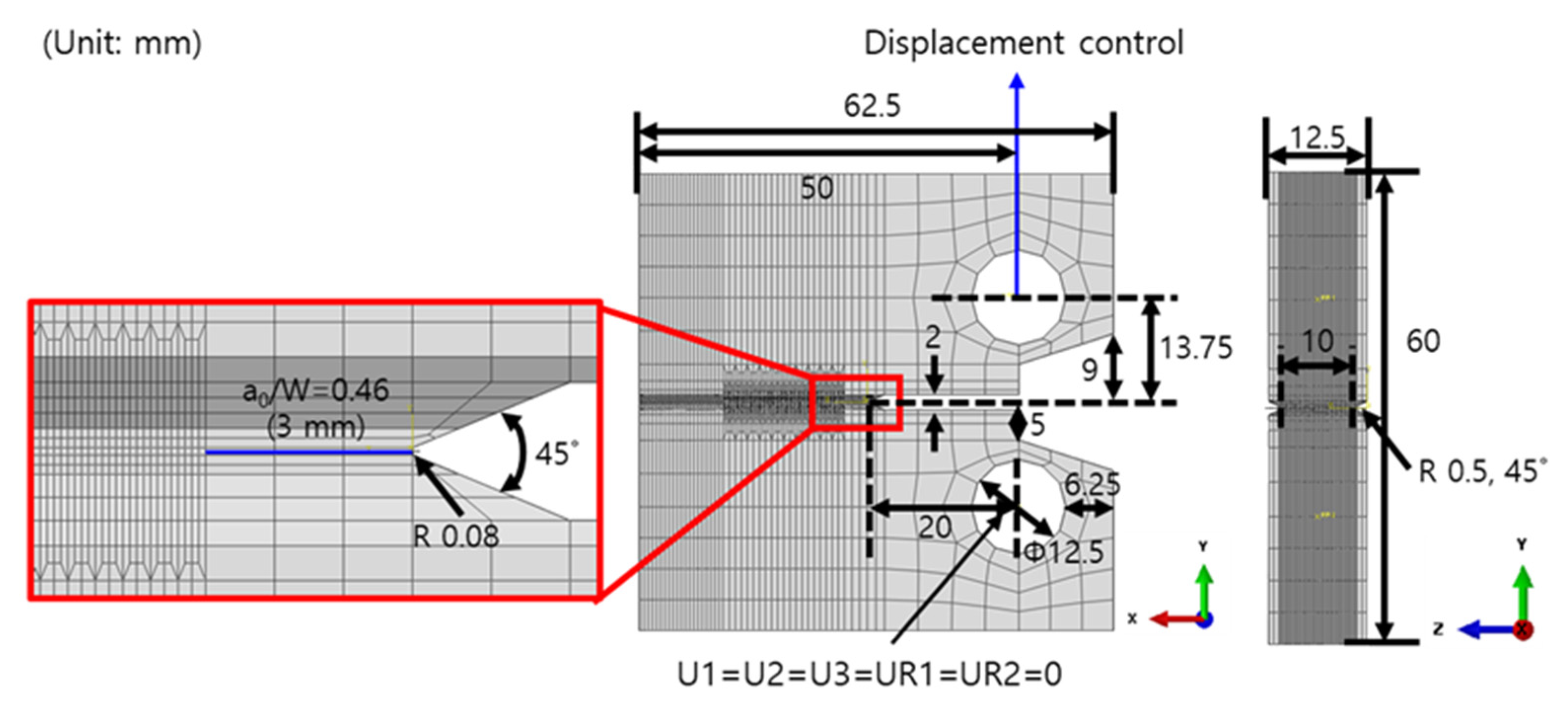
Figure 6 shows a schematic and the FE model of the mirrored ½T-CT specimen. The in-plane geometry was modeled according to the ASTM 1820 standard. Because simulating crack initiation and propagation is computationally intensive, fine 100 μm elements were used to mesh only the crack tip, and the rest of the material was coarsely meshed. The resulting FE model consisted of 152,302 nodes and 144,792 C3D8R elements. The thickness of the ½T-CT specimen was 12.5 mm and the minimum thickness at the roots of the side grooves was 10 mm. The side grooves were modeled with an angle of 45° and a radius of 0.5 mm. A specimen width of 50 mm and a0/W of 0.46 with a fatigue pre-crack length of 3 mm, notch height of 2 mm, notch angle of 45°, and a pin diameter of 12.5 mm were set as the same as those of experiments. The parameters derived from the SSRT specimens were used for the ½T-CT specimens. To avoid any unnecessary constraints and increase accuracy, a 3-dimensional model was used for the specimen.
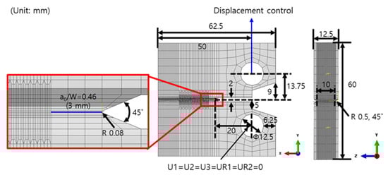
Figure 6.
Schematic and FE model of the CT specimen.
Both holes of the ½T-CT specimen were controlled using reference points. The bottom hole was fixed and the upper hole was vertically displaced. XFEM was used only for the notch section. The simulations were conducted until the average crack extension was 3 mm. The fracture resistance curves and JQ values were estimated according to the ASTM 1820 standard. The analysis method was verified by comparing the results for the ½T-CT specimens made of SA372 steel in the presence of 100% noble and hydrogen gases at a pressure of 62.5 MPa with those of experiments. This was then repeated for the ½T-CT specimens made of Al6061-T6 alloy to predict their fracture properties.
4.2. Analysis Results and Discussion
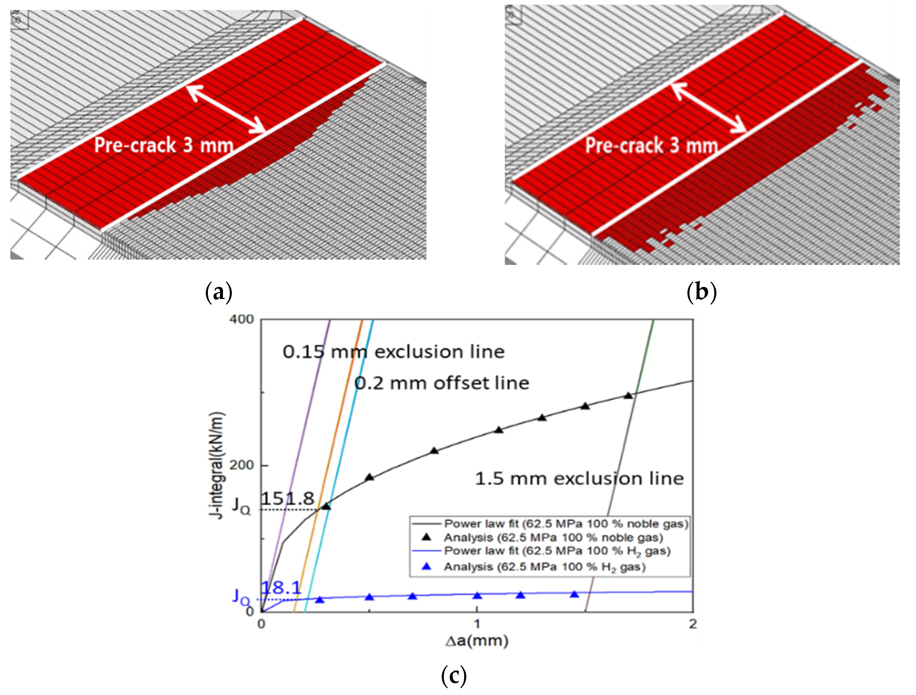
Figure 7a,b show the crack extensions of the ½T-CT specimen made of SA372 steel under two conditions. The red elements with values of 1 indicate a complete fracture. The cracks propagated in a semi-elliptical shape. The average crack extensions at the same load-line displacement were 0.96 and 1.76 mm for 62.5 MPa noble and hydrogen gases, respectively. The analyses were conducted until an average crack extension of 3 mm was reached. The resulting fracture resistance curves are shown in Figure 7c. Construction lines were plotted following the ASTM 1820 standard, and the data between 0.15 and 1.5 mm was fitted with a power law equation of the form J = C1(∆a)C2. The JQ values were estimated from the point where the 0.2 mm construction line and the power law curve intersected, and the values for each condition were 151.8 and 18.1 kN/m. In contrast, the JQ values derived from the experimental results were 143.4 kN/m and 14.0 kN/m. Thus, differences in the JQ values between experiments and analyses were 8.4 and 4.1 kN/m. Although the JQ values did not meet the size requirements to be the JIC due to the inherently thin geometry of the ½T-CT specimen examined in this study, the method was verified by comparing experimental and analytical results.
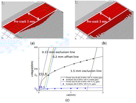
Figure 7.
Results of ½T-CT specimen made of SA372 steel: (a) crack extension (62.5 MPa noble gas condition); (b) crack extension (62.5 MPa hydrogen gas condition); and (c) fracture–resistance curves. (The purple color represents blunting line, the orange color represents 0.15 mm exclusion line and the skyblue color represents 0.2 mm offset line.)
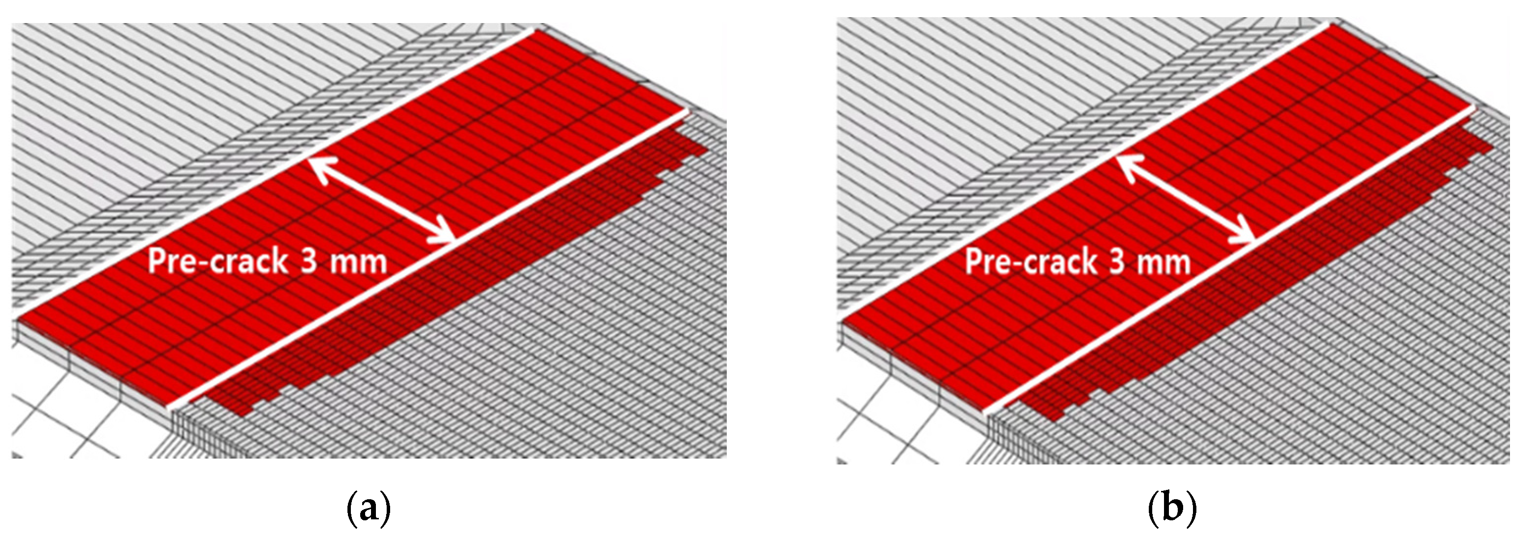
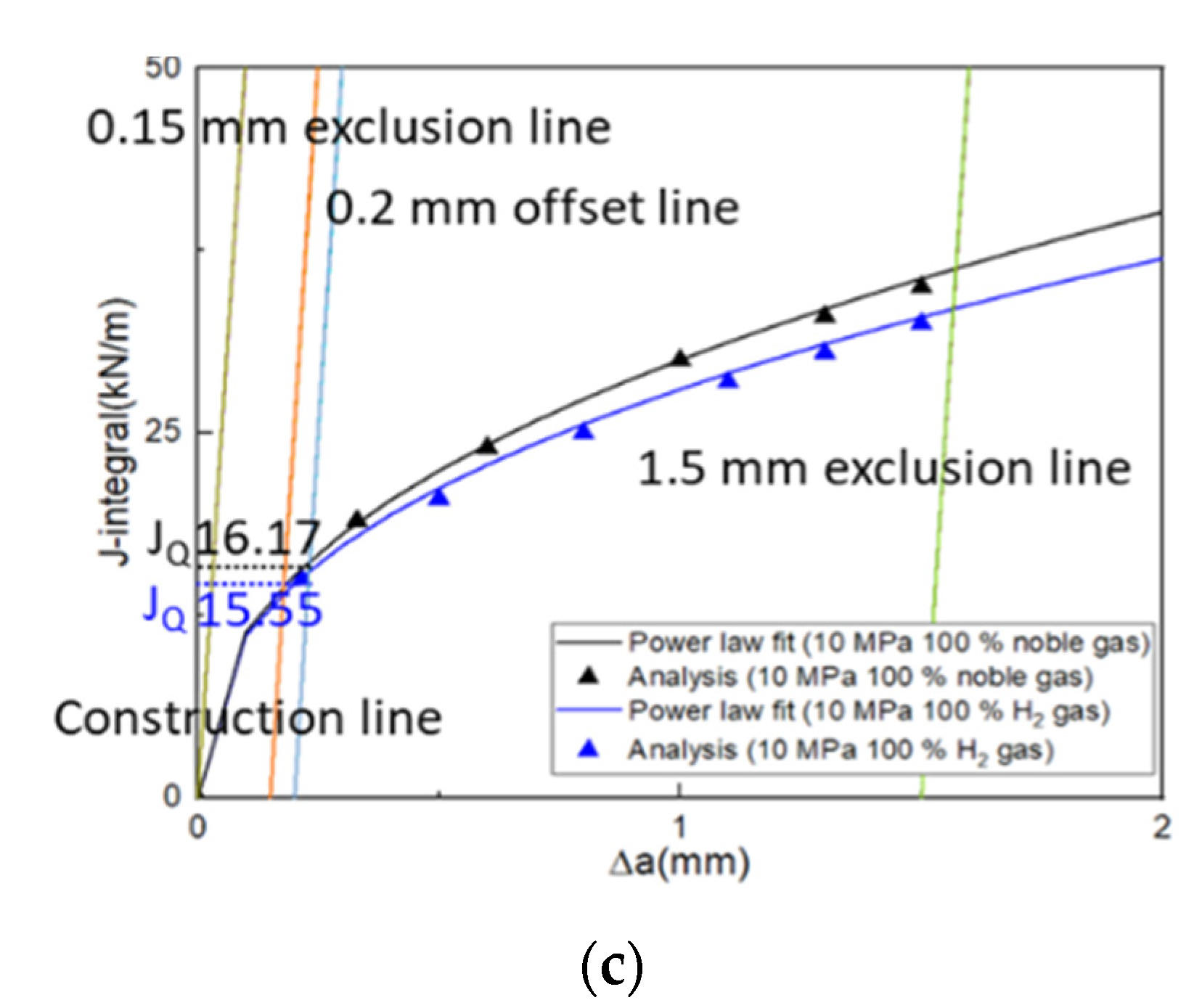
The analysis results including crack extensions for the ½T-CT specimens made of Al6061-T6 alloy under the two conditions are shown in Figure 8. The cracks were semi-elliptical in shape and propagated more toward the center than along the surface of the specimen for all conditions. The trend of simulated crack propagation profiles was consistent with that observed in an experimental study [27]. The difference in crack extension between the two conditions was within 1%. In a manner similar to that described earlier, the estimated JQ values of the above specimen for the two gas conditions were 16.17 and 15.55 kN/m, of which the difference was small compared with that of SA372 steel.
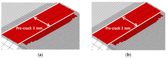
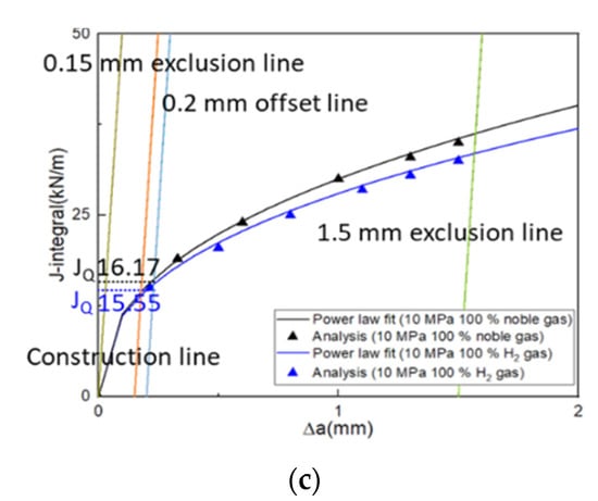
Figure 8.
Results of ½T-CT specimen made of Al6061-T6 alloy; (a) crack extension (10 MPa noble gas condition); (b) crack extension (10 MPa hydrogen gas condition); and (c) fracture–resistance curves. (The green color represents blunting line, the orange color represents 0.15 mm exclusion line and the skyblue color represents 0.2 mm offset line.)
5. Conclusions
In this study, the effects of hydrogen gas on the fracture properties of two representative metallic materials were investigated. A series of numerical procedures using XFEM with MIGA was suggested, which was validated for SA372 steel and then applied to Al6061-T6 alloy. Key findings from the relevant experiments and analyses were summarized as follows:
- The XFEM damage parameters of the Al6061-T6 alloy and SA372 steel were derived using SSRT specimens. The maximum differences in the load and total displacement between the experiments and analyses were within 5% for all materials and conditions;
- Experiments and analyses on ½T-CT specimens made of SA372 steel were performed in the presence of noble and hydrogen gases. For both cases, fracture resistance curves were compared. The differences in JQ values in the presence of noble and hydrogen gases were 8.4 kN/m and 4.1 kN/m, respectively. This suggests that the analysis method was reasonable;
- The JQ value of SA372 steel was determined following the ASTM 1820 standard. The JQ value in the presence of 62.5 MPa hydrogen gas was observed to be significantly lower (by a factor of 88.1%) than that in the presence of 62.5 MPa noble gas;
- The JQ values of the Al6061-T6 alloy were derived in a similar manner, and it was observed to be lower by only 3.8% for the ½T-CT specimen in the presence of 10 MPa hydrogen gas. This suggests that the behavior of Al6061-T6 alloy is not affected by hydrogen gas.
Author Contributions
Formal analysis and writing—original draft, D.-H.K.; data curation and validation, M.J.P.; supervision and writing—review and editing, Y.-S.C.; investigation and writing—review and editing, U.B.B. All authors have read and agreed to the published version of the manuscript.
Funding
This work was supported by the Korea Agency for Infrastructure Technology Advance-ment (KAIA) grant funded by the Ministry of Land, Infrastructure, and Transport (Grant 19TLRP-C152334-01). This work was also supported by the Korea Institute of Energy Technology Evaluation and Planning (KETEP) and the Ministry of Trade, Industry, and Energy (MOTIE) of the Republic of Korea (No. 20211710200020).
Data Availability Statement
Not applicable.
Conflicts of Interest
The authors declare no conflict of interest.
References
- Robertson, I.M.; Sofronis, P.; Nagao, A.; Martin, M.L.; Wang, S.; Gross, D.W.; Nygren, K.E. Hydrogen Embrittlement Understood. Metall. Mater. Trans. B 2015, 46, 1085–1103. [Google Scholar] [CrossRef]
- Safyari, M.; Moshtaghi, M.; Kuramoto, S.; Hojo, T. Influence of microstructure-driven hydrogen distribution on environmental hydrogen embrittlement of an Al–Cu–Mg alloy. Int. J. Hydrogen Energy 2021, 46, 37502–37508. [Google Scholar] [CrossRef]
- Safyari, M.; Moshtaghi, M.; Kuramoto, S. On the role of traps in the microstructural control of environmental hydrogen embrittlement of a 7xxx series aluminum alloy. J. Alloys Compd. 2021, 855, 157300. [Google Scholar] [CrossRef]
- Matsuoka, S.; Yamabe, J.; Matsunaga, H. Criteria for determining hydrogen compatibility and the mechanisms for hydrogen assisted, surface crack growth in austenitic stainless steels. Eng. Fract. Mech. 2016, 153, 103–127. [Google Scholar] [CrossRef]
- Nguyen, T.T.; Park, J.; Kim, W.S.; Nahm, S.H.; Beak, U.B. Effect of low partial hydrogen in a mixture with methane on the mechanical properties of X70 pipeline steel. Int. J. Hydrogen Energy 2020, 45, 2368–2381. [Google Scholar] [CrossRef]
- Nguyen, T.T.; Heo, H.M.; Park, J.; Nahm, S.H.; Beak, U.B. Damage assessment and mechanical performance of Cr-Mo steel used in hydrogen storage vessels. Eng. Fail. Anal. 2021, 120, 105031. [Google Scholar] [CrossRef]
- Zhou, D.; Li, T.; Huang, D.; Wu, Y.; Huang, Z.; Xiao, W.; Wang, Q.; Wang, X. The experiment study to assess the impact of hydrogen blended natural gas on the tensile properties and damage mechanism of X80 pipeline steel. Int. J. Hydrogen Energy 2021, 46, 7402–7414. [Google Scholar] [CrossRef]
- Guy, P.; Laszlo, T.; Julien, C. Effects of Hydrogen Addition on Design, Maintenance and Surveillance of Gas Networks. Processes 2021, 9, 1219. [Google Scholar] [CrossRef]
- Sérgio, E.R.; Antunes, F.V.; Neto, D.M.; Borges, M.F. Study on the Influence of the Gurson–Tvergaard–Needleman Damage Model on the Fatigue Crack Growth Rate. Metals 2021, 11, 1183. [Google Scholar] [CrossRef]
- Belytschko, T.; Black, T. Elastic crack growth in finite elements with minimal remeshing. Int. J. Numer. Methods Eng. 1999, 45, 601–620. [Google Scholar] [CrossRef]
- Fageehi, Y.A. Fatigue Crack Growth Analysis with Extended Finite Element for 3D Linear Elastic Material. Metals 2021, 11, 397. [Google Scholar] [CrossRef]
- Kim, D.H.; Sim, J.M.; Chang, Y.S.; Baek, U.B. Hydrogen gaseous effects on fracture resistance of API-X70 estimated by XFEM. J. Mech. Sci. Technol. 2021, 35, 3829–3835. [Google Scholar] [CrossRef]
- Neri, F.; Rostami, S. Generalised Pattern Search Based on Covariance Matrix Diagonalisation. SN Comput. Sci. 2021, 2, 171. [Google Scholar] [CrossRef]
- Pyo, C.; Kim, J.; Kim, J. Estimation of Heat Source Model’s Parameters for GMAW with Non-linear Global Optimization—Part I: Application of Multi-island Genetic Algorithm. Metals 2020, 10, 885. [Google Scholar] [CrossRef]
- Dassault Systems. ABAQUS User’s Manual Ver. 2020. Available online: https://help.3ds.com/2020/english/dssimulia_established/SIMULIA_Established_FrontmatterMap/sim-r-DSDocAbaqus.htm?contextscope=all&id=9a5d7bf209394446819332b397a93f40 (accessed on 9 August 2022).
- Dassault Systems. Isight User’s Manual Ver. 2020. Available online: https://help.3ds.com/2020/english/dssimulia_established/SIMULIA_Established_FrontmatterMap/sim-r-DSDocIsight.htm?contextscope=all&id=436c7e04627c44b8972c6ef47f3da711 (accessed on 9 August 2022).
- ASTM International. ASTM G142-98 Standard Test Method for Determination of Susceptibility of Metals to Embrittlement in Hydrogen Containing Environments at High Pressure, High Temperature, or Both; ASTM International: West Conshohocken, PA, USA, 2011. [Google Scholar]
- ASTM International. ASTM E8/E8M-08 Standard Test Methods for Tension Testing of Metallic Materials; ASTM International: West Conshohocken, PA, USA, 2008. [Google Scholar]
- ASTM International. ASTM G129-00 Standard Practice for Slow Strain Rate Testing to Evaluate the Susceptibility of Metallic Materials to Environmentally Assisted Cracking; ASTM International: West Conshohocken, PA, USA, 2006. [Google Scholar]
- ASTM International. ASTM 1820-13 Standard Test Method for Measurement of Fracture Toughness; ASTM International: West Conshohocken, PA, USA, 2013. [Google Scholar]
- Kim, D.H.; Je, S.Y.; Chang, Y.S. Investigation of cracking behaviors in divertor armor-blocks under cyclic loading. Fusion Eng. Des. 2021, 169, 112464. [Google Scholar] [CrossRef]
- Gairola, S.; Jayaganthan, R. XFEM Simulation of Tensile and Fracture Behavior of Ultrafine-Grained Al 6061 Alloy. Metals 2021, 11, 1761. [Google Scholar] [CrossRef]
- Yang, K.; Zhang, Y.; Zhao, J. Elastoplastic Fracture Analysis of the P91 Steel Welded Joint under Repair Welding Thermal Shock Based on XFEM. Metals 2020, 10, 1285. [Google Scholar] [CrossRef]
- Hu, X.; Xu, J.; Du, X.; Zhang, Y.; Zhou, F. Research on Fatigue Crack Propagation of 304 Austenitic Stainless Steel Based on XFEM and CZM. Metals 2020, 10, 727. [Google Scholar] [CrossRef]
- Holland, J.H. Adaptation in Natural and Artificial Systems: An Introductory Analysis with Applications to Biology, Control, and Artificial Intelligence; The MIT Press: Cambridge, MA, USA, 1992. [Google Scholar] [CrossRef]
- Goldberg, D.E. Genetic Algorithms in Search, Optimization and Machine Learning; Addison-Wesley Longman Publishing Co., Inc.: Boston, MA, USA, 1989. [Google Scholar]
- Mahanty, D.K.; Maiti, S.K. Experimental and finite element studies on mode I and mixed mode (I and II) stable crack growth—I. Experimental. Eng. Fract. Mech. 1990, 37, 1237–1250. [Google Scholar] [CrossRef]

Publisher’s Note: MDPI stays neutral with regard to jurisdictional claims in published maps and institutional affiliations. |
© 2022 by the authors. Licensee MDPI, Basel, Switzerland. This article is an open access article distributed under the terms and conditions of the Creative Commons Attribution (CC BY) license (https://creativecommons.org/licenses/by/4.0/).