Abstract
The joint is a key component of the aviation piping system, with severe performance requirements and better requirements for connection technology. With a focus on the manufacturing demand of AA6061 aerospace pipe joints, as well as the characteristics of EMP forming technology, this paper investigates the deformation behavior of the EMP forming on AA6061 aerospace pipe joints, the influence of process parameters on the deformation behavior, and the deformation mechanism of the tube wall. The results show that under the conditions of this paper, with an increase in the initial tube-sleeve gap and discharge voltage, the degree of local deformation of the AA6061 tube wall and the trench embedding rate increase. Keeping the width and depth of the grooves as 1.14 mm and 0.23 mm, the embedding rate of the grooves is less than 85% under the clearance conditions of 0.11 mm and 0.5 mm, while the lowest voltage for the embedding rate of the grooves to reach more than 85% under the clearance conditions of 1 mm, 1.5 mm and 2 mm is 7 kV, 6 kV, and 5 kV, respectively. The metallographic organization of the deformation area shows that the tube is deformed by the intense shear at the edge of the groove of the tube sleeve, thereby showing streamlined organization characteristics and deformation characteristics. The electromagnetic pulse forming process of the AA6061 tube is mainly divided into two stages: free bulging and local deformation; the inertia of high-rate deformation causes the groove filling to exhibit volume deformation characteristics in the local deformation stage.
1. Introduction
There are thousands of pipes in the aircraft engine, which is the most important lifeline of the aircraft [1]. Among them, the piping joints are the key parts of the piping system, and their quality is related to the comprehensive performance of the piping system, and even the whole aircraft. Piping joints are not only subjected to high temperatures, low temperatures, and high-frequency vibrations externally but they are also subjected to the pulsating impact of the fluid medium internally, which is a harsh working environment. With the increasing requirements for lightweight, pressure resistance, sealing, and green manufacturing, traditional connection technologies (such as melt welding, copper brazing, and adhesive bonding) can hardly meet the performance requirements of pipeline joints. As a result, new pipeline joint-forming technologies are urgently needed [2].
At present, separable pipe joints are one of the main forms of aviation pipe joints, which are divided into three types: flare, non-flare, and lip seal, among which, the non-flare pipe joints have higher reliability and can withstand certain vibrations and pressure pulsations.
The non-flare joint is a groove of a certain size preset on the inner wall of the pipe sleeve, and the pipe is bulged and embedded in the groove of the pipe sleeve through a suitable forming process to form a stable pipe joint. The quality of the pipeline joints depends on the degree of groove embedding. Limited by the requirements of the lightweight aviation pipeline system, the geometric features of the grooves in the inner wall of the tube sleeve are small, and the pipe bulge embedded in the grooves to form pipe joints is a local deformation. The current forming technologies mainly include features such as inner-diameter-roll-forming technology and elastic media extrusion technology.
Inner-diameter-roll forming uses rollers that are gradually fed into the pipe in the axial direction to exert radial pressure on the pipe material. It also rotates at the same time as the axial feeding, so as to ensure that all areas of the ring can be deformed. As the rollers are fed in, the pipe is deformed locally and flows into the grooves in the inner wall of the sleeve to form the pipe joint [3]. The strength of the pipe joint is provided by both the radial contact forces between the pipe and the sleeve forming a “force closure joint”. The pipe embedded in the sleeve groove also forms a “shape closure joint”, with the latter playing a major role and the joint strength increasing as the groove depth increases. The latter plays a major role and the strength of the joint increases as the depth of the groove increases [4]. As can be seen, the process is easy to operate with low-forming loads. However, the inner roller and the tube are easily eccentric during the forming process, resulting in uneven circumferential forming.
The elastic-media-extrusion forming technique produces internal pressure by axially squeezing the elastic media to expand and squeeze the pipe into the groove of the sleeve. Since the modulus of elasticity of the sleeve is greater than that of the tube, an interference pressure is generated between the tube and the sleeve after forming, so that the outer surface of the tube is closely bonded to the inner wall of the sleeve to resist the working pressure inside the tube [5]. Ramezani et al. [6] numerically studied the frictional behavior between rubber and metal during the extrusion of elastic media. The process of expanding an aluminum alloy tube by compressing the rubber was simulated by Belhassen et al. [7]. The process requires the identification of a suitable elastic medium depending on the tube and the amount of deformation. At the same time, an appropriate level of friction between the medium and the pipe needs to be achieved, which will affect the service life of the elastic medium.
In addition to the two forming techniques above, there are other pipe-joint forming techniques that correspond to the forming needs of aerospace pipe joints. Henriksen et al. [8] proposed a method for joining pipes and grooved sleeves by expanding a rigid die with bumps. Przybylski et al. [9] proposed a method for forming lightweight pipe joints by rolling from the outer diameter and noted that joints with trapezoidal grooves have higher pull-off strength compared to circular grooves. Cai D et al. [10] proposed a method for the electro-hydraulic joining of aluminum alloy tubes and stainless-steel pipe sleeves and found that the joint performance improved with increasing discharge voltage and slot width. At the same time, additive manufacturing (AM) plays an important role in process 4.0 due to its flexibility and may be able to produce joints, but there are few relevant studies [11].
The electromagnetic-pulse joining technique is a typical deformation joining technique that achieves the mechanical or metallurgical joining of tubular members by an instantaneous high-rate deformation and has received much research and application in the field of tube joining [12]. Park YB et al. [13] observed that even though the tube joints formed mechanically by magnetic pulse loading, the failure of the joint was in the form of a fracture of the parent material. They also pointed out that the groove depth and the radius of the groove fillet were the main factors affecting joint strength. Christian W et al. [14] formed a lightweight automotive frame tube joint by shrinking the outer tube and embedding it in the mandrel groove through a magnetic pulse connection. Christian W [15] found that the tube and mandrel produced a greater shear at the rectangular groove, resulting in a stronger joint than the circular groove.
In summary, the magnetic-pulse connection is applied to tube-to-tube and tube-to-shaft connections by reducing the diameter of the outer tube, and typical research and application results have been obtained. From the viewpoint of the technical characteristics of the magnetic-pulse connection, the technology has been used to form non-flaring pipe joints, which can not only overcome the shortcomings of the inner-diameter-roll forming technology of uneven circumferential forming but also can significantly improve the “tool” life compared to the elastic-media-extrusion-forming technology. At the same time, magnetic-pulse joining technology can also precisely control the effect of the local deformation of the pipe. However, the existing studies have shown that the EMP forming area for joining purposes is large, and the aerospace pipe joints rely on the micro-groove filling of the pipe sleeve to achieve the connection, which will lead to a significantly different overall deformation of the pipe, i.e., the local deformation behavior of micro-groove filling and the connection mechanism and process control from the general pipe EMP mechanical connection.
To this end, this paper will analyze the effect of each experimental parameter on the forming effect through a series of experiments on the magnetic-pulse deformation connection of pipe joints. It will also analyze the local deformation pattern of pipes and the effect of filling the grooves through metallographic observation. The paper will also examine the overall deformation process and the deformation behavior of micro-groove filling through numerical simulations of magnetic pulse connection of pipe joints to reveal the deformation and filling mechanism of pipes to the micro-groove of the pipe sleeve.
2. Experiment and Establishment of Finite Element Model
2.1. Process Principle
The electromagnetic pulse connection principle of the pipeline joint is shown in Figure 1. After closing the discharge switch, the capacitor discharges instantaneously, which generates a large impulse current on the coil and a strong pulsed magnetic field. Due to the law of electromagnetic induction, an induced current is generated on the pipe, and its direction is opposite that of the coil’s current direction. Under the action of two opposite magnetic fields, the pipe is bulged at a high rate by the Lorentz force, and the pipe joint is formed in the prefabricated groove of the filling pipe sleeve.
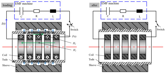
Figure 1.
Principle of EMP connection technology for pipe joints.
In practical applications, a typical aviation pipeline joint material matches the AA6061-T4 pipe and AA7075-T6 pipe sleeve. In order to study the deformation process of the 6061 aluminum alloy pipe and the influence of various process parameters on the magnetic pulse forming of pipe joints, experimental studies were carried out by changing the initial gap between the pipe fittings and casing, the discharge voltage, and the geometric characteristics of pipe casing grooves. For the convenience of experimental research, this paper replaces the actual AA7075-T6 sleeve with a steel simulated sleeve (i.e., mold) that has similar mechanical properties as the sleeve.
2.2. Experimental Conditions and Experimental Protocol
The shape and dimensions of the pipe material and the simulated sleeve are shown in Figure 2, and the initial dimensions are shown in Table 1. No. 45 steel with a yield strength of 335 MPa and tensile strength of 600 MPa was used as the simulated sleeve material, and the hardness of the sleeve mold was increased by heat treatment to ensure the effect of repeated experiments and to avoid interference from other factors. At the same time, in order to reduce the experimental cost, the tube sleeve mold was designed as a split flap type, which is convenient to disassemble directly after forming to observe and measure the local deformation effect of the tube.
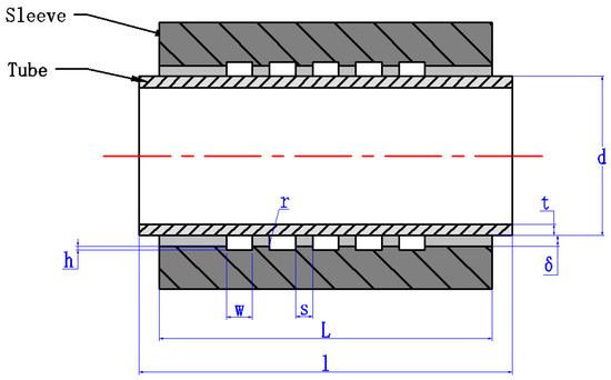
Figure 2.
Schematic diagram of different groove depths of pipe sleeve model.

Table 1.
Table of dimensional parameters of the tube-tube sleeve model.
In order to locate the coil, pipe, and simulated pipe sleeve, the device shown in Figure 3 was designed, and the radial alignment of the pipe sleeve, pipe, and coil was realized by opening a series of positioning holes and mating surfaces, for details, see section A-A in Figure 3.
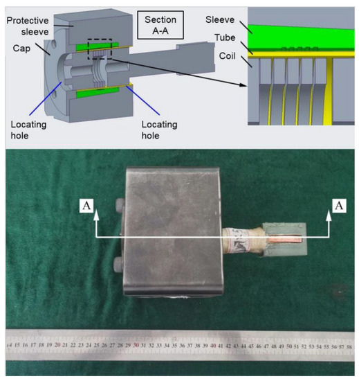
Figure 3.
Experiment equipment and models.
The process test used EMF-50/18 type electromagnetic forming equipment (Harbin Institute of Technology, Harbin, China) with a capacity of 304 μF, a maximum discharge energy of 50 kJ, and a maximum discharge voltage of 18 kV.
First, the effect of the initial tube-sleeve gap δ and voltage on forming was investigated, and five initial gaps of 0.11 mm, 0.5 mm, 1 mm, 1.5 mm, and 2 mm were designed under the condition that the width and depth of the groove were 1.14 mm and 0.23 mm. By keeping the test tube size constant, the gap was adjusted by changing the inner diameter of the tube sleeve. Tests were conducted under five gap conditions, while each gap had a corresponding different discharge voltage, and the experimental design is shown in Table 2.
Table 2.
Variable tube-tube sleeve initial gap and voltage process parameter settings.
It has been suggested that the radius r of the groove fillet has a significant effect on the joint and that there is an optimum value of radius r for a given groove depth, which balances the shear action with the strength of the joint [12]. However, the wall thickness of the tube in previous studies was much less than the depth and width of the groove [13]. The wall thickness of the tube in this study was much greater than the depth of the groove, and its deformation characteristics were characterized by volumetric deformation, which is significantly different from the general plate deformation. Therefore, the initial gap of the tube-tube sleeve selected was 1 mm, the discharge voltage was 7 kV, as shown in Figure 4, and the radii of the rounded corners r of five grooves were 0.15 mm, 0 mm, 0.05 mm, 0.1 mm, 0.2 mm, respectively, set from left to right in the same sleeve die. In addition, the depth and width of the grooves were kept constant at 0.23 mm and 1.14 mm.
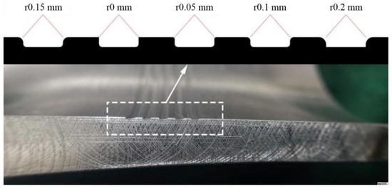
Figure 4.
Schematic of the dimensions of the variable fillet radius pipe sleeve.
2.3. Finite Element Model and Reliability Verification
In the numerical simulation of this paper, in order to improve computational efficiency, the 2D axisymmetric model is adopted. The 3D model is consistent with the 2D axisymmetric model in the geometric dimension, and the main difference is the difference in the torus Angle.
In LS-DYNA, for the 3D model, the EM_Solver developed by LS-DYNA (ANSYS 19.0, Pennsyivania, PA, USA) adopts the finite element and boundary element algorithm. The computational efficiency of the solver is low, but the modeling is simple, and it is suitable for most numerical simulations of electromagnetic forming. For 2D-axially symmetric models, the 2D axisymmetric EM_solver developed by LS-DYNA is able to solve the electromagnetic field equation in a two-dimensional plane, and then expand the two-dimensional electromagnetic field, Lorentz force, and Joule heat into 3D elements by rotating around the axis. This allows the 2D electromagnetic field to be coupled with the 3D force field and temperature field, thus greatly reducing the computational time and keeping the 3D functionality of LS-DYNA available [16]. The solver is only suitable for the model with good axial symmetry, and the electromagnetic bulging process of pipe fittings has good axial symmetry, so it is appropriate to use the solver.
In order to verify the reliability of the numerical model, a 3D model and a 3D axisymmetric model of 6061-T4 aluminum alloy pipe fitting were established. The free bulging test and numerical simulation were carried out under the discharge voltage of 4 kV, as shown in Figure 5. The results of the test, 3D model, and 2D axisymmetric model are basically consistent. The length of the forming zone L and the maximum outside diameter D of the pipe fitting are measured and compared with the simulation results, as shown in Table 3. It can be found that the error between the length of the forming zone L and the maximum outside diameter D of the pipe fitting and the test results is less than 10% in both the 3D model and the 2D axially symmetric model, which indicates that the numerical simulation results are reliable.
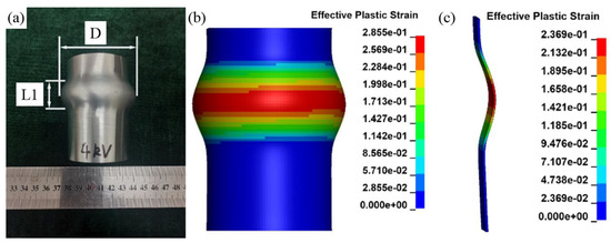
Figure 5.
Comparison between experimental and numerical simulation results. (a) Test results; (b) 3D model simulation results; (c) 2D axisymmetric model simulation results.
Table 3.
Comparison of deformation results between test and simulation results.
There are three main parts in this process: coil, tube, and sleeve. In order to constrain the ring direction of the tube sleeve, the sleeve ring part is added, which is consistent with the actual forming. Considering that the tube, sleeve, and coil all belong to an axisymmetric pattern and are placed symmetrically with the axis, this direct electromagnetic expansion connection has good axial symmetry.
Firstly, the finite element model of the coil and tube was established in LS-Prepost (LS-Prepost 4.7.7, LS-Prepost, USA) software. The model was 1/64 of the whole, the outer diameter of the tube was 49.2 mm, the wall thickness was 0.9 mm, and the length was 33.8 mm. The coil was made of red copper, the cross-section was 3 mm × 7 mm, the number of turns was 5, and each turn of the coil was a separate part. All components adopt single point integration elements and finally form the finite element model as shown in Figure 6. The element grid setting of the finite element model is shown in Table 4.
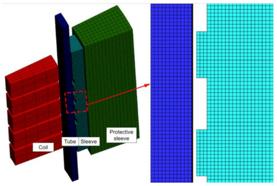
Figure 6.
Finite element model of magnetic pulse forming of pipe joint.
Table 4.
Element mesh setting in finite element model.
The temperature has little influence on the forming effect during the process of electromagnetic bulging of pipe fittings, so only the electromagnetic field and force field are considered in the simulation. In the simulation of this paper, two kinds of materials are used to simulate the pipe sleeve. Firstly, a 45 steel is used for simulation, and the simulation results are compared with the actual experiments to illustrate the accuracy of the simulation. Secondly, AA7075-T6 was used as the pipe sleeve material to simulate the deformation behavior of the pipe fitting. The mechanical property parameters of each component are set as shown in Table 5. In the numerical simulation, the coil and the sleeve ring are set as rigid bodies. In this model, only the tube and the sleeve are in contact, and the contact is set as double-sided contact. The static friction coefficient is 0.15, and the dynamic friction coefficient is 0.1.
Table 5.
Finite element model mechanical properties’ parameter settings.
In the electromagnetic field, the circuit adopts RLC series resonance circuit parameter input, Rsys, Lsys, and Csys as the circuit input parameters, namely, the system inductance, capacitance, and resistance. In the numerical simulation of this paper, the EMF50 kJ/18 kV electromagnetic forming equipment of the Key Laboratory of Metal Hot Working of Harbin Institute of Technology is adopted. The oscilloscope and Roche coil (Power Electronic Measurements Ltd., Nottingham, UK) are used to measure the current under 3 kV discharge voltage, as shown in Figure 7. According to the RLC parameters fitted by the measured current curve, the Rsys, Lsys, and Csys of the electromagnetic forming system were 14.86 mΩ, 0.675 µH, and 304 µF, respectively. By inputting circuit parameters such as Rsys, Lsys, and Csys in the circuit Settings and presetting the initial charging voltage, the discharge process with the same voltage can be simulated in the real situation.
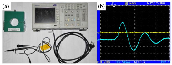
Figure 7.
Finite element model of magnetic-pulse forming of pipe joint. (a) Oscilloscope and Roche coil; (b) Measured current curve (3kV).
LS-DYNA was used to analyze the deformation behavior of pipe joints during magnetic-pulse forming. Since the magnetic-pulse forming process of the pipe joint belongs to the category of high-rate forming, the influence of the strain rate on the material model needs to be considered. In the numerical simulation, the material model of the pipe and the pipe sleeve adopted the simplified Johnson–Cook (J–C) model, which reflects the strain and strain rate hardening effects caused by high-speed deformation. To save the solution time, the effect of the temperature field was not considered in the model:
where
σ is the flow stress of the material (MPa)
is the strain rate (s−1), is the plastic strain
is the reference strain rate (s−1)
According to Zhang P et al. [17] and Børvik et al. [18], it can be known that the J–C model parameters of AA6061-T4 and AA7075-T6 are shown in Table 6.
Table 6.
J–C model parameters of pipe and casing materials [17,18].
In order to simplify the calculation, the sleeve and the sleeve were set as insulators, and the coil was used as the source conductor to couple with the set circuit. The conductivity was 5.71 × 10⁷ S/m, the tube was used as an induction conductor to generate an induced current under the action of an electromagnetic field, and the conductivity was 2.31 × 10⁷ S/m. Among them, the coil components were connected with the keyword *EM_CIRCUIT_CONNECT to form a complete current loop, and the circuit input still used the RLC parameter input.
Since the model is axisymmetric, constraints are set in the direction of the pipe and sleeve rings. Since the actual length of the pipe fitting is much longer than the sleeve, full constraints are set on the two end faces of the pipe fitting. The coil and the sleeve ring basically do not deform or move during actual forming, and the coil and the sleeve ring are also set with full rigid body constraints.
2.4. Deformation Observation
In this paper, the laser confocal electron microscope (OLS-3000) (Hitachi OLYMPUS, Tokyo, Japan) was used to observe and measure the contour size of the deformed area of the 6061 pipe fitting after forming.
After the 6061-T4 aluminum alloy pipe fitting is formed, the instrument is used to scan the deformation area of the pipe fitting to obtain the three-dimensional morphology of the pipe fitting, and the contour line can be drawn along the axis direction of the pipe fitting and generate coordinate points. Due to the presence of other interference sources in the test process, the test results will be affected to a certain extent. Based on the test results, noise reduction should be unified to obtain the scanning contour of the deformation area of the pipe fitting. The height of the deformation area of the pipe fitting can be obtained by processing the data coordinates of the contour.
In order to further analyze the local deformation degree of the pipe fitting, the formed pipe fitting was cut along the radial direction, and the section and metallographic structure of the local deformation area were observed by optical microscope. The samples were cut along the radial direction in the deformation zone of the 6061 aluminum alloy pipe fitting. After grinding and polishing with sandpaper, the samples were corroded with corrosion solution (HF:HNO3:H2O = 1:3:6) for more than 15 s. The metallographic structure of the pipe fitting before and after forming was observed by a metallographic microscope.
3. Results and Analysis
3.1. Experiment Results of Magnetic Pulse Connection
The quality of aviation pipeline joints is directly related to the fitting degree of the pipe-pipe sleeve grooves. In this paper, the fitting rate of the pipe groove is used as the evaluation index of the connection result. When the fitting rate reaches 85%, the connection strength of the pipe joints is high.
3.1.1. Influence of Voltage and Gap
From the experimental results, it can be seen that the deformation of the tube wall was small at discharge voltages of 6–8 kV when the initial tube-sleeve gap was 0.11 mm. At 6 kV, as the initial tube-sleeve gap increased, the degree of the tube and sleeve embedding gradually increased, but none of the tubes reached a relative 85% fill rate.
The scanning position was selected in the deformation zone of the tube with a discharge voltage of 7 kV and a gap of 1 mm. Six scanning lines were selected along the circumferential direction to obtain the 3D morphology shown in Figure 8, with the X direction in the axial direction, the Y direction in the circumferential direction, and the Z direction in the radial direction. The green area is the raised area, i.e., the deformation zone where the tube was embedded in the groove after forming. The profile was drawn as shown in Figure 9. As shown in Figure 9a, draw the lower limit of the contour coordinate of the pipe fitting deformation area under 6 kV discharge voltage to the same horizontal line, take the mean value of the high coordinate area and the low coordinate point area of the curve in the figure, and put the low coordinate point to 0, and further obtain the approximate contour as shown in Figure 9b. Within the margin of error caused by roughness, the height of the deformed area was more consistent, indicating a more uniform forming in the circumferential direction.
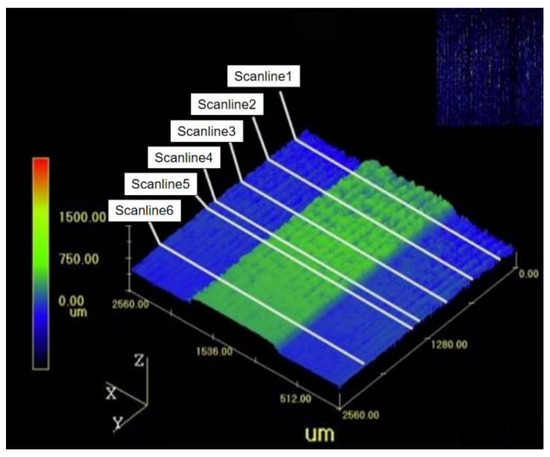
Figure 8.
Laser confocal scanning 3D morphology.
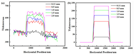
Figure 9.
Fitted and approximate contours for different initial gaps at 6 kV discharge voltage. (a) Fitted profile; (b) Approximate profile.
As shown in Figure 9a, it can be seen from the graph that there were fluctuations in the z-coordinate of the points on the scan line. After data noise reduction processing and mean fitting, it was found that the tube forming height increased with the initial gap at the same voltage. It is clear that the increase in the forming height was the most pronounced from 0.11 mm to the 0.5 mm gap. As the gap increased further, the forming height of the tube gradually approached the trench depth of 0.23 mm, but the increasing value of the filling increment gradually decreases. The forming height already exceeded 0.2 mm at the 1.5 mm gap condition, i.e., the trench embedment rate exceeded 85%.
On the other hand, the effect of the discharge voltage on deformation at 1 mm initial gap conditions is shown in Figure 10. The depth of the trench filling increased with an increasing voltage, with forming heights of 154.07 µm, 171.19 µm, and 201.92 µm at 5 kV, 6 kV, and 7 kV discharge voltages, respectively.
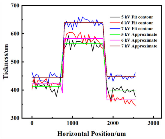
Figure 10.
Local deformation profile for different discharge voltages at 1 mm initial gap.
The effect of the initial gap and the release point voltage on the groove-filling effect is shown in Table 7. As the simulated tube sleeve (i.e., mold) groove was basically not deformed, the groove embedding rate was calculated by the local deformation height. It can be seen that under 0.11 mm and 0.5 mm gap conditions, the local deformation height was not above 0.2 mm and the trench embedding rate was less than 85%. However, under 1 mm, 1.5 mm, and 2 mm gap conditions, the minimum voltage at which the trench embedding rate reached above 85% was 7 kV, 6 kV, and 5 kV, respectively.
Table 7.
Height of local deformation of the tube (µm) for different initial gaps and discharge voltages.
To observe the consistency of the degree of deformation in each trench, the side walls of the tubes of the three test pieces with voltages of 7 kV and gaps of 1.0–2.0 mm were cut along the radial direction, as shown in Figure 11a–c, and the sections were observed through an optical microscope. It can be seen that the height of the five bumps was relatively consistent across the three test pieces, indicating that the degree of localized deformation of the tube in each trench was uniform. Further measurements yielded average forming heights of 0.203 mm, 0.224 mm, and 0.229 mm, respectively, which were in good agreement with the results obtained from the laser confocal microscope measurements. The average depth of depression in the inner wall of the tube was 0.187 mm, 0.211 mm, and 0.198 mm, respectively.
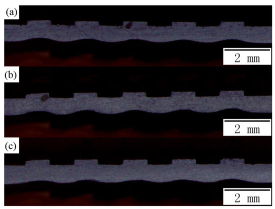
Figure 11.
Cross-sectional observation of the tube deformation zone under different initial clearance conditions at 7 kV discharge voltage. (a) 1 mm gap; (b) 1.5 mm gap; (c) 2 mm gap.
3.1.2. Effect of Tube Sleeve Groove Dimensions
At an initial gap of 1 mm and a discharge voltage of 7 kV, the effect of the groove fillet angle on the filling deformation is shown in Figure 12a and the measurement of the raised dimensions is shown in Figure 12b. As the radius of the groove fillet increases, the height of the deformation decreases.
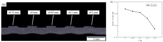
Figure 12.
Sections of pipe deformation zone under different groove fillet radii. (a) Actual photo; (b) Influence of fillet radius on bump height.
The metallographic organization of the filled deformation region was observed for different groove fillet radii, as shown in Figure 13. As shown in Figure 13a, there is a very obvious local shear effect at the edge of the groove when there is no rounding. As the radius of the groove fillet r increases, the shear effect in the groove edge area gradually decreases, and the degree of grain deformation decreases. When the radius of the groove fillet reached 0.2 mm, as shown in Figure 13e, the local shearing effect basically disappeared. The weakening of the shearing action helped to reduce the degree of material thinning at the edge of the groove, where micro-cracks were less likely to occur, which is beneficial to the fatigue life of the joint.
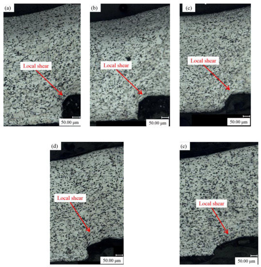
Figure 13.
Metallographic structure of deformed area of pipe with different fillet radii. (a) No fillet. (b) Groove fillet radius 0.05 mm. (c) Groove fillet radius 0.1 mm. (d) Groove fillet radius 0.15 mm. (e) Groove fillet radius 0.2 mm.
On the other hand, as the radius of the groove fillet increased, the shape of the pipe projection changed from rectangular to almost trapezoidal, the fillet of the root of the projection coincided with the radius of the groove fillet, and the root of the deformation zone became more rounded while the height of the deformation zone decreased. This inevitably resulted in a reduction of joint strength at this point. Therefore, there is an optimum value for the radius of the groove fillet. In conjunction with the cross-sectional profile of the deformation zone shown in Figure 12, it can be seen that at a radius r of 0.05 mm, the pipe bulge is still clearly rectangular and 0.202 mm in height, and as can be seen in Figure 13b, the shearing effect of the deformation zone at this radius is also considerably reduced compared to that without rounding. Therefore, by taking into account the fatigue life of the joint and the strength of the joint, the optimum radius of the groove fillet r is 0.05 mm, which corresponds to a groove depth w = 0.23 mm and a groove width h = 1.14 mm.
3.1.3. Local Deformation Feature Analysis
Taking the initial gap of 2 mm, a voltage of 7 kV, and a groove fillet radius of 0.05 mm as an example of forming a pipe, the metallographic structure is shown in Figure 14. Before and after the tube was formed, the grain structure of the busbar and the deformation zone of the tube wall changed significantly.
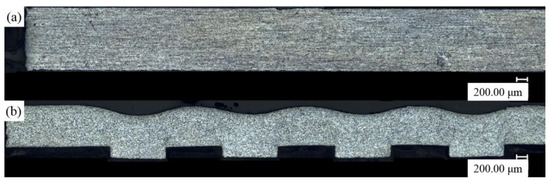
Figure 14.
Overall metallographic structure of the pipe. (a) Before Forming. (b) After Forming.
Further observation of the local structure shown in Figure 15a shows that the rolling direction of the pipe before deformation is along the axial direction of the pipe, and its grain orientation is also in this direction. The pipe material squeezed into the groove from both sides after forming; its flow direction is shown in Figure 15b. A severe shearing effect occurred at the edge of the groove, that is, the groove fillet area. The metal grains were severely elongated and deformed into the groove, forming a streamlined grain structure, and the closer it was to the edge of the groove, the more obvious this streamlined feature was. This was similar to the forging streamline in the forging process, indicating that the local deformation zone of the pipe exhibited volumetric deformation characteristics.
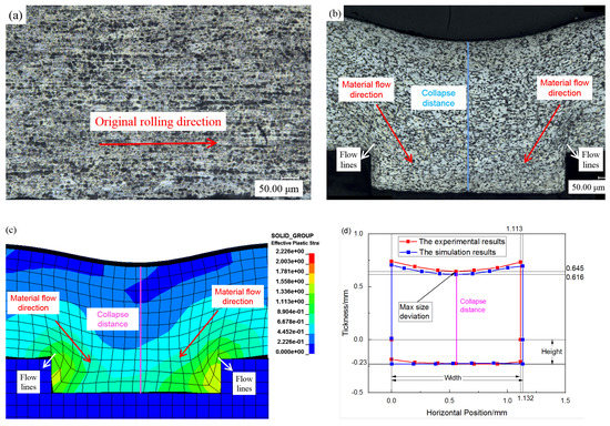
Figure 15.
Comparison of local metallographic structure of tubing with simulation results. (a) Before Forming. (b) After Forming. (c) Simulation Results. (d) Comparison of the Superimposed Shapes.
This volume deformation feature was achieved by magnetic pulse forming of the tube, which reflects the advantages of magnetic pulse forming technology applied to pipe joints, i.e., the ability to achieve intense large deformation in local areas on the tube wall. This process not only avoids the large tonnage loads required for conventional volume forming but also achieves the desired local deformation effect.
At the same time, the initial clearance of the sleeve is set to be 2 mm, and the material of the sleeve is 45 steel. Numerical simulation is carried out under the same discharge voltage of 7 kV, and the simulation results are shown in Figure 15c. It can be seen that the simulated deformation area has the same metal flow direction and metal flow line as the actual experiment. After measurement, the superimposed image obtained by comparing experimental and numerical data is shown in Figure 15d. In the actual experiment, the width and height of the bulge in the deformation area are 1.113 mm and 0.23 mm, respectively, and the collapse distance of the bulge is 0.875. In the simulation, the convex width and height of the deformation area are 1.132 mm and 0.23 mm, respectively, and the collapse distance at the corresponding position of the bulge is 0.846. The size difference is less than 5%, which indicates that the simulation results have a certain accuracy.
3.2. The Deformation Behavior Analysis
The initial gaps between the pipe and the casing were set as 0.11 mm, 0.5 mm, 1 mm, 1.5 mm, and 2 mm, respectively, and numerical simulations were carried out under the same 6 kV discharge voltage.
Under the same discharge voltage, the forming effect under different initial clearances is shown in Figure 16, with an increase in the initial gap between the tube and the tube, as shown in Figure 16c, the area where the tube was deformed and embedded in the groove of the tube kept becoming larger to the bottom of the trench. As shown in Figure 17, with an increase in the gap between the pipe and the casing, the peak velocity of the unit in the deformation zone of the pipe also increased, and the peak velocity was as high as 278.7 m/s under the 2 mm gap. The groove edge area was severely deformed, resulting in the phenomenon of “collapse”, as shown in Figure 16e.
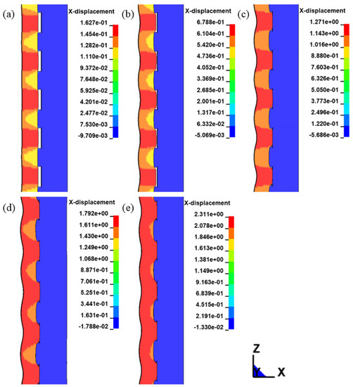
Figure 16.
Forming effect under different initial gaps. (a) 0.11 mm (b) 0.5 mm (c) 1 mm (d) 1.5 mm (e) 2 mm.
Figure 17.
Variation curve of element velocity with time under different initial gap conditions.
In the case of only focusing on 6061 fitting local deformations, a naturally big initial gap and voltage can cause more severe local deformation, but from the perspective of the forming effect of the actual pipe joint, on the one hand, pipe— the set of an initial gap will make the pipe—set of a preset clearance is difficult, even pipe fittings happened in the preset clearance deformation strengthening. On the other hand, it can be found from the numerical simulation results that the groove edge of the sleeve is crushed under the condition of excessive clearance and voltage. Therefore, when the embedding rate of the pipe joint is more than 85%, a smaller gap should be selected to avoid the phenomenon of groove edge collapse.
The groove embedment rate was measured under the conditions of different pipe-tube sleeve initial gaps. As shown in Figure 18, the embedment rate was 88.7% under the condition of a 1 mm initial gap, which reached the requirement of 85%. When the gap reached 1.5 mm and 2 mm, the groove embedment rate was close to 100%, but the groove edge “slumped”. Therefore, in the variable gap electromagnetic bulging process scheme, the initial gap and discharge voltage should be selected to be as small as possible while ensuring the groove embedding rate, so as to avoid the phenomenon of serious deformation of the sleeve’s groove edge. From the point of view of the forming effect under a discharge voltage of 6 kV, it is appropriate to select the initial gap between the pipe and casing of 1 mm. At this time, the forming process of the pipe joint is shown in Figure 19.
Figure 18.
Variation of intercalation rate under different initial gaps at 6 kV discharge voltage.
Figure 19.
Forming process of pipeline joint with initial gap of 1 mm and discharge voltage of 6 kV. (a) 0 µs (b) 12 µs (c) 15 µs (d) 16 µs (e) 16.5 µs (f) 17.5 µs.
The magnetic pulse forming process of the pipe joint is divided into two stages: the first stage is the free expansion stage of the pipe before the collision between the pipe and the sleeve, and the other is the local deformation stage where the pipe and the sleeve collide and deform into the groove. The free expansion stage lasts for a relatively long time, as shown in Figure 19a–c. As can be seen from the three-way stress curves for the four cells in Figure 20a, the tube is subjected to a two-way tensile state, i.e., annular tensile stress σθ, axial tensile stress σz, and radial stress σr, which is negligible.
Figure 20.
Analysis of stress state in deformation area of pipeline joint during forming process. (a) Element A stress change curve. (b) Element B stress change curve. (c) Element C stress change curve. (d) Element D stress change curve. (e) Schematic diagram of the overall stress state change.
When the tube collides with the sleeve, the area of the tube that corresponds to the sleeve groove continues to deform into the groove, which is a critical stage in the forming of the pipe joint. As shown in Figure 20d–f, the localized deformation phase occurs in a very short time, with the tube material being largely embedded in the sleeve groove area in only 2.5 µs. During this phase, significant localized plastic deformation of the tube occurs, with the maximum equivalent plastic strain increasing from 0.04457 prior to the collision to 1.067 and occurring at the edge of the groove. This is due to the strong shear that occurs at the edge of the groove after the collision between the tube and sleeve, resulting in significant plastic deformation. This strong shear is accompanied by a dramatic change in the stress state, as shown in Figure 20a–d, where all four units in the deformation zone are in a free-expanding stress state before the collision. These units become a three-way compressive stress state after the collision with the sleeve, and from the point of time when the units collide with the sleeve, units A and B on the tube wall collide with the sleeve first, followed by unit D and finally unit C. This indicates that the process of embedding the tube in the trench is from the center of the trench first and gradually expands to the sides, resulting in a streamlined mesh, as shown in Figure 20e, which is similar to the flow of metal in a forging process. This is consistent with the metallographic structure observed by the metallography microscope in Section 3.1.3.
The variation of the strain state in the deformation zone is shown in Figure 21. For the analysis of one element, the variation of its strain state is shown in Figure 21a. The strain state of the deformation zone unit is in a plane strain state before the tube contacts the sleeve, with circumferential elongation, radial compression, and a negligible axial strain of almost zero, as shown in Figure 21b. When the tube contacts the sleeve, the strain state in the deformation zone changes rapidly from a plane strain state in the free expansion phase to a three-way strain state: radial compression, axial elongation, and circumferential elongation. This illustrates the unique advantages of the EMP forming process in achieving local volume deformation of thin-walled tubes by tube forming, and the reasons for this are a matter for research.
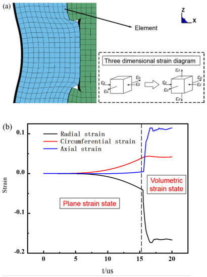
Figure 21.
Analysis of the strain state of the deformation zone during the forming process of the pipe joint. (a) Element strain state change. (b) Element three-dimensional strain change curve.
There are two main reasons why the magnetic pulse forming process realizes the local volume deformation of the pipe in the form of pipe forming: one is the effect of the Lorentz force in the electromagnetic field, where the Lorentz force squeezes the pipe material into the groove. In the direct bulging process scheme, the pipe speed is only tens of meters per second, and this factor plays a major role.
The second scheme is to convert kinetic energy into deformation energy, which is especially obvious in the variable-gap electromagnetic bulging scheme. As shown in Figure 22 setting the keyword can extract the energy change data in the process of tube magnetic-pulse forming. Under the condition of maintaining the discharge voltage at 6 kV, when the initial gap between the pipe and the casing is 0.11 mm, the kinetic energy of the pipe is low. When the pipe collides with the casing, the deformation energy increases slowly, which means that the pipe’s deformation energy increases slowly during the impact. The deformation energy is mainly provided by the Lorentz force. When the initial gap between the pipe and the casing increases to 1 mm, the kinetic energy of the pipe increases significantly, and when the pipe collides with the casing, the kinetic energy drops rapidly, and the deformation energy rises rapidly. At this time, the deformation energy of the pipe is mainly composed of transformed kinetic energy.
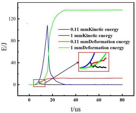
Figure 22.
Variation of pipe energy during deformation under different gaps of 6 kV discharge voltage.
The transformation of kinetic energy into deformation energy is largely due to the inertial effect under high-speed impact. The velocity distribution of the pipe in the deformation zone was further analyzed. As shown in Figure 23, six elements are selected in the deformation zone, among which elements 1 and 2 are in the non-grooved area, unit 3 is in the groove edge area, and units 4, 5, and 6 are in the groove area. It can be seen from Figure 23b that in the free-bulging stage, the velocity of all units changes with time while the curves are basically the same. Before the collision, the radial velocity of the pipe element reaches 195.2 m/s. As the pipe collides with the pipe sleeve, the pipe enters the local deformation stage, and the element velocity changes significantly. Unit 1 and element 2 of the pipe first contact the pipe sleeve. After the collision, the speed drops rapidly. This kind of collision is an incomplete inelastic collision, which causes the velocity drop to become negative, that is, the velocity becomes reversed. Because unit 3 is located in the edge area of the groove, it can enter the groove through deformation, so its speed is higher than that of unit 1 and unit 2, and it falls more slowly. On the other hand, units 4, 5, and 6 in the groove area can be due to the inertia effect that continues to move into the groove. There is also an acceleration interval under the action of the Lorentz force, as shown in Figure 23b, and under the action of the electromagnetic force, it continues to accelerate to the speed peaks until it comes into contact with the sleeve, and then its speed does not increase. As a result, the speed starts to drop rapidly, and it can be seen from the peak point in the figure that among the three units, the peak speed of unit 4 is the largest, followed by unit 5, and unit 6 is the smallest. This means that cell 6 contacts the socket first, cell 5 second, and cell 4 last.
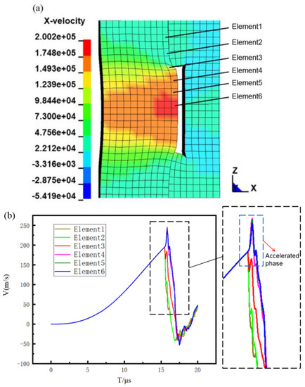
Figure 23.
Analysis of element velocity in groove region. (a) Trench Deformation Zone Cell Position (16.25 µs). (b) Unit speed versus time curve.
4. Conclusions
The purpose of this paper was to study the factors affecting the forming of 6061 aluminum alloy aviation pipe joints in the process of dynamic electromagnetic-pulse forming, the forming process of the pipe, and the local deformation mechanism. Therefore, experiments, metallographic observations, and finite element simulations were carried out on the pipe joints to analyze the influence of different process parameters such as reserved gap, discharge voltage, and groove size on the forming, and to study the mechanism of local forming. These are the following conclusions from this paper:
- 1.
- As the initial gap and discharge voltage increase, the degree of local deformation of the tube also increases, and the trench embedding rate increases. The minimum voltages for deformation heights of 0.2 mm or more at 1 mm, 1.5 mm, and 2.0 mm gaps were 7 kV, 6 kV, and 5 kV, respectively. By observing the metallographic organization of the deformed area of the tube, it was found that the local deformation of the magnetic pulse was accompanied by intense shearing, the grains were severely deformed and elongated in the direction of the groove, and a streamlined organization emerged at the edge of the groove. As the radius r of the groove fillet increased, the height of the local deformation decreased, and the shape changed from rectangular to trapezoidal, with a consequent increase in the root fillet of the deformation zone, resulting in a decrease in the joint strength at this point. On the other hand, an increase in the radius of the groove fillet r reduced the shearing effect at the edge of the groove. Considering both, the optimum radius of the groove fillet r is 0.05 mm, which corresponds to a groove depth of 0.23 mm and a groove width of 1.14 mm.
- 2.
- In this study, a 2D axisymmetric model is used for finite element simulation, which saves greatly on computational costs. According to the results of the finite element simulation, the embedding rate is 88.7% under the condition of 1 mm initial clearance, which has reached the requirement of 85%. When the clearance reaches 1.5 mm and 2 mm, the groove embedding rate is close to 100%, but groove edge “collapse” occurs. Therefore, in the process of electromagnetic bulging with a variable gap, a small initial gap and discharge voltage should be chosen as far as possible to avoid the serious deformation of the tube groove edge under the condition of ensuring the groove embedding rate. According to the forming effect under a 6 kV discharge voltage, it is appropriate to choose a 1 mm initial gap between the tube and sleeve.
- 3.
- The magnetic-pulse forming process for pipe joints is divided into two stages: the first being the free expansion of the pipe and the second being the process where the pipe is locally deformed and embedded in the groove, where the local deformation is characterized by volume deformation. This local volume deformation of the pipe by means of magnetic-pulse loading in the same way as conventional pipe forming is mainly due to the direct action of the Lorentz force and the conversion of kinetic energy into deformation energy, with the latter accounting for an increased proportion as the initial gap between the pipe and the sleeve increases.
Author Contributions
Writing—review and editing: H.Y. and B.M.; investigation: H.Y.; supervision: H.Y.; validation: H.Y.; funding acquisition: H.Y.; writing—original draft: B.M.; methodology: Y.H.; date curation: Y.H.; test materials: Y.Q.; testing plan and investigation: Y.Q. All authors have read and agreed to the published version of the manuscript.
Funding
This research was funded by the National Natural Science Foundation of China, grant number 52175304.
Data Availability Statement
The data presented in this study are available in the article.
Acknowledgments
The authors gratefully acknowledge the financial support of the National Natural Science Foundation of China (Grant No. 52175304).
Conflicts of Interest
The authors declare no conflict of interest.
References
- Yang, H.; Li, H.; Zhang, Z.; Zhan, M.; Liu, J.; Li, G. Advances and Trends on Tube Bending Forming Technologies. Chin. J. Aeronaut. 2012, 25, 1–12. [Google Scholar] [CrossRef]
- Li, H.; Fu, M. Deformation-Based Processing of Materials; Elsevier: Amsterdam, The Netherlands, 2019; ISBN 9780128143827. [Google Scholar]
- Yang, J.; Li, H.; Huang, D.; Li, G. Deformation-based joining for high-strength Ti-3Al-2.5V tubular fittings based on internal roller swaging. Int. J. Mech. Sci. 2019, 171, 105367. [Google Scholar] [CrossRef]
- Zhang, R.X.; Wu, W.; Zeng, Y.S. Research on connection strength of flare less internal rolling tube joint. Aeronaut. Manuf. Technol. 2016, 22, 84–88. [Google Scholar] [CrossRef]
- Yang, J.C.; Li, H.; Huang, D.; Li, G.; Yuan, S. Forming of thin-walled AA6061-T4 tubular joint by elastomeric bulging: Experiment and computation. Int. J. Adv. Manuf. Technol. 2020, 107, 25–38. [Google Scholar] [CrossRef]
- Ramezani, M.; Ripin, Z.M.; Ahmad, R. Computer aided modelling of friction in rubber-pad forming process. J. Mater. Process. Technol. 2009, 209, 4925–4934. [Google Scholar] [CrossRef]
- Belhassen, L.; Koubaa, S.; Wali, M.; Dammak, F. Anisotropic effects in the compression beading of aluminum thin-walled tubes with rubber. Thin-Walled Struct. 2019, 119, 902–910. [Google Scholar] [CrossRef]
- Henriksen, J.; Nordhagen, H.O.; Hoang, H.N.; Hansen, M.R.; Thrane, F.C. Numerical and experimental verification of new method for connecting pipe to flange by cold forming. J. Mater. Process. Technol. 2015, 220, 215–223. [Google Scholar] [CrossRef]
- Przybylski, W.; Wojciechowski, J.; Klaus, A.; Marré, M.; Kleiner, M. Manufacturing of resistant joints by rolling for light tubular structures. Int. J. Adv. Manuf. Technol. 2006, 35, 924–934. [Google Scholar] [CrossRef]
- Cai, D.; Liang, J.; Ou, H.; Li, G.; Cui, J. Mechanical properties and joining mechanism of electrohydraulic expansion joints for 6063 aluminum alloy/304 stainless steel thin-walled pipes. Thin-Walled Struct. 2021, 161, 107427. [Google Scholar] [CrossRef]
- Khorasani, M.; Loy, J.; Ghasemi, A.H.; Sharabian, E.; Leary, M.; Mirafzal, H.; Cochrane, P.; Rolfe, B.; Gibson, I. A review of Industry 4.0 and additive manufacturing synergy. Rapid Prototyp. J. 2022, 28, 1462–1475. [Google Scholar] [CrossRef]
- Saha, P.K. Electromagnetic Forming of Various Aircraft Components. SAE 2005, 114, 2–11. [Google Scholar] [CrossRef]
- Park, Y.-B.; Kim, H.-Y.; Oh, S.-I. Design of axial/torque joint made by electromagnetic forming. Thin-Walled Struct. 2005, 43, 826–844. [Google Scholar] [CrossRef]
- Weddeling, C.; Woodward, S.T.; Marré, M.; Nellesen, J.; Psyk, V.; Tekkaya, A.E.; Tillmann, W. Influence of groove characteristics on strength of form-fit joints. J. Mater. Process. Technol. 2010, 211, 925–935. [Google Scholar] [CrossRef]
- Weddeling, C. Electromagnetic Form-Fit Joining. Ph.D. Thesis, Dortmund University of Technology, Dortmund, Germany, 2015. [Google Scholar] [CrossRef]
- L‘Eplattenier, P.; Çaldichoury, I. Recent developments in the Electromagnetic Module: A new 2D axi-symmetric EM solver. In Proceedings of the 10th European LS-DYNA Conference, Würzburg, Germany, 15 June 2015; Available online: https://www.dynalook.com/conferences/10th-european-ls-dyna-conference (accessed on 19 July 2021).
- Zhang, P.H. Joining Enabled by High Velocity Deformation. Ph.D. Thesis, The Ohio State University, Columbus, OH, USA, 2003. [Google Scholar]
- Børvik, T.; Hopperstad, O.S.; Pedersen, K.O. Quasi-brittle fracture during structural impact of AA7075-T651 aluminum plates. Int. J. Impact Eng. 2010, 37, 537–551. [Google Scholar] [CrossRef]


Publisher’s Note: MDPI stays neutral with regard to jurisdictional claims in published maps and institutional affiliations. |
© 2022 by the authors. Licensee MDPI, Basel, Switzerland. This article is an open access article distributed under the terms and conditions of the Creative Commons Attribution (CC BY) license (https://creativecommons.org/licenses/by/4.0/).