Article

Laser Powder Bed Fusion of Intermetallic Titanium Aluminide Alloys Using a Novel Process Chamber Heating System: A Study on Feasibility and Microstructural Optimization for Creep Performance

by
Reinhold Wartbichler
1,*,
Tobias Maiwald-Immer
2,
Fabian Pürstl
1 and
Helmut Clemens
1
1
Department of Materials Science, Montanuniversität Leoben, Franz-Josef-Str. 18, 8700 Leoben, Austria
2
AM Metals GmbH, Zoxy-Platz 1, 09633 Halsbrücke, Germany
*
Author to whom correspondence should be addressed.
Metals 2022, 12(12), 2087; https://doi.org/10.3390/met12122087
Submission received: 30 September 2022 / Revised: 10 November 2022 / Accepted: 19 November 2022 / Published: 5 December 2022
(This article belongs to the Special Issue Intermetallics for Structural Applications)

Abstract

:
A laser powder bed fusion process operating at elevated temperatures is introduced capable of fabricating crack-free and dense intermetallic titanium aluminide alloy specimens as well as demonstrator components using a base plate heating up to 900 °C and a unique heating system of the uppermost powder bed layer up to 1200 °C. Two so-called 4th generation alloys, TNM and TNM+, were used for this study. The microstructure and its evolution during subsequent heat treatments were investigated and explained by employing scanning electron microscopy, hardness testing, X-ray diffraction, differential scanning calorimetry and thermodynamic equilibrium calculation. Selected specimens were subjected to creep tests at 750 °C. The microstructures after processing consist of extraordinarily fine lamellar γ-TiAl/α2-Ti3Al-colonies with globular γ and βo-TiAl grains for both the TNM and TNM+ alloy, exhibiting a microstructure gradient from the last consolidated powder layer down to the starting layer due to cellular reaction, which increases the amount of globular γ and βo at the boundaries of the γ/α2-colonies. During annealing in proximity to the γ-solvus temperature, banded microstructures might form, as the α-grain size is only partially controlled by heterogeneously distributed γ/β-phase, which stems from the process-related Al loss. Additionally, the occurrence of thermally-induced porosity is investigated. Optimizing the microstructure to a homogenized, almost fully lamellar microstructure, involved annealing in the β-single phase field region and led to improved creep properties. Finally, TNM demonstrator components with complex geometries, such as aero engine blades and turbocharger turbine wheels, are fabricated by employing the novel laser powder bed fusion process.

1. Introduction

Additive manufacturing (AM), as a transformative technology, has matured from its roots in the 1980s—then known as rapid prototyping [1]—via applications in tooling into modern-day industry-scale component production [2,3]. Its nature offers advantages compared to traditional and subtractive manufacturing technologies, including reduced waste, reduced lead times and buy-to-fly ratios, stockpiles as well as cost [2,4,5]. Furthermore, complex geometries involving cooling channels and lattice structures are realizable. AM processes such as laser powder bed fusion (LPBF) and electron beam melting (EBM), named after their respective energy sources for selectively melting the powder bed [5,6,7], made their entrance in the automotive and aeronautical industries. Here these novel manufacturing technologies came in contact with certain material classes with a predisposition for application in such industries, such as titanium aluminides based on the intermetallic γ-TiAl phase. These lightweight γ-TiAl-based alloys offer high specific strength and Young’s modulus, as well as creep performance when compared to polycrystalline Ni-base alloys at a temperature regime from 600 to 800 °C [8]. The low density of γ-TiAl-based alloys (ρ~3.9–4.2 g·cm−3) makes them attractive candidates to substitute the aforementioned Ni-base alloys (ρ~8.0–8.5 g·cm−3) for components such as casings, vanes, shrouds or turbine blades, where weight savings up to 50% can be realized [9,10]. Climate change makes the increase of engine efficiency as well as the reduction of CO2, NOx and noise emissions paramount [11,12,13]. Against that background, General Electric started the use of cast Ti-48Al-2Cr-2Nb alloy (compositions stated in at.%, unless stated otherwise) into service as low-pressure turbine (LPT) blade material for the 6th and 7th stage of the LPT of the GEnX civil aircraft engine in 2006 [14]. Then Pratt & Whitney introduced the so-called TNM alloy with a nominal composition of Ti-43.5Al-4Nb-1Mo-0.1B in the last LPT stage of the geared turbofan engine [15]. The TNM alloy is a 4th generation TiAl alloy utilizing a disordered body-centered cubic (bcc) β-phase at elevated temperature, which enables hot-forging with near-conventional methods because a sufficient number of slip systems is provided [11,12,16]. The TNM alloy is, therefore, considered a process-adapted TiAl alloy. Recently, the TNM alloy was refined further to offer an increased creep resistance and microstructural stability by small additions of C and Si with a nominal composition of Ti-43Al-4Nb-1Mo-0.1B-0.3C-0.3Si and, thus, named TNM+ alloy [17].
In general, processability is considered a challenge for intermetallic TiAl alloys due to the high reactivity of the TiAl melt, the existence of a brittle-to-ductile transition, deterioration of ductility when interstitial impurity contents surpass 0.1 m.% and the distinctive dependency of the mechanical properties on the microstructure [9,10,18]. Coming back to the AM technologies, EBM processing limits the pickup of interstitial impurities via the controlled vacuum environment and enables fabrication at an elevated process temperature above the brittle-to-ductile transition temperature of TiAl alloys (~700 °C) [5,10,19,20]. Crack-free components can, thus, be manufactured when the processing parameters are adequately chosen. In addition, the rapid cooling rates limit segregations to smaller length scales, which makes larger components a possibility, as segregations otherwise cause microstructural heterogeneity [18,20,21]. However, a common feature of γ-TiAl-based alloys produced via EBM is the process-parameter dependent Al evaporation [22,23], leading to the appearance of banded microstructures [24,25,26,27] as well as the occurrence of solidification textures due to high thermal gradients [28].
Both the EBM and LPBF processes operate by selectively melting a pre-applied powder bed, which is raked onto a substrate plate that is then lowered and the process repeated until the job is finished [3,5,29]. Compared to EBM, the LPBF process offers a higher manufacturing accuracy and the option to integrate cooling channels and undercuts into the design because of the use of a fine powder fraction [30], which makes the process interesting for components with high geometrical complexity.
During the standard LPBF build process, a thin powder layer of 20–80 µm is applied on the base plate. In turn, a laser with a spot diameter of ~80 µm scans a sliced cross-section of the 3D-model. The processes of recoating a powder layer and welding a sliced cross-section are repeated layer by layer until the desired geometry is built and the job is finished. Today’s LPBF printers for industrial manufacturing are equipped with a base plate heating reaching temperatures between 200 °C and 500 °C. However, these standard machines cannot be used to process intermetallic TiAl alloys because of the material’s specific complex requirements on constant and elevated temperature conditions, as well as on exceptionally low O content. Residual stresses, shrinkage, oxygen absorption and the comparably low ductility of TiAl alloys result in cracks and recoater crashes during the LPBF process. Systems relying only on higher base plate temperatures are also not sufficient to print crack-free samples and parts with high geometrical complexity exhibiting large dimensions in build direction (i.e., large build heights). The pre-heating effect of the base plate decreases with increasing build height and at a certain build height the necessary pre-heating temperature for TiAl cannot be reached anymore.
Taking these TiAl-specific material requirements into account, AM Metals GmbH have designed a preproduction model based on the well-established EOS-M290 system. The EOS-M290-HT (high temperature) is equipped with a high-temperature modification kit, which also includes cooling of the process chamber and an inert gas purification system, as well as additional process monitoring and data logging (Figure 1a). Mizuta et al. [31] used the same machine with an identical heating unit and oxygen control system as the authors in this paper to fabricate LPBF samples of the 2nd generation Ti-48Al-2Cr-2Nb alloy and compared them to EBM counterparts. The LPBF specimens showed better tensile properties and finer, more homogeneous microstructures. However, the feasibility of producing TiAl components with complex geometries by LPBF has not yet been shown. In this study, the adapted novel LPBF machine was utilized to produce demonstrator components showing such complex geometries.
Previous publications focused on parameter studies to seek out the applicable process windows and suitable scan strategies [30,32,33,34,35,36] with a special focus on limiting the likelihood of crack formation and obtaining high densities [4,7,30,34]. Lately, a density of 99.9% was also reported for a LPBF-TNM alloy in the as-built state [35]. Furthermore, fabrication at an elevated temperature appears promising to lower the chance of cracking due to thermal stresses. Pre-heating temperatures up to 1000 °C via inductively heated baseplates have already been applied, as reported in [30,34,35,37]. Aluminum, with its high vapor pressure, is prone to evaporation during the LPBF process [30,32,34,35], which might alter the properties of components. The Al loss can be reduced by lowering the volume energy density EV [J·mm−3] [30], as given in Equation (1):
E V = P L v s · h s · l s ,
where PL is the laser power [W], vs is the scan speed [mm·s−1], hs is the hatch distance [µm] and ls represents the layer thickness [µm].
The mechanical properties of TiAl alloys are highly dependent on the prevailing microstructure [10]. Hence, it remains mandatory to hot-isostatically press (HIP) TiAl components to close any processing-related porosity [21] stemming from AM or any other conventional manufacturing process. Subsequently, the microstructure is adjusted carefully to the respective application by a heat treatment procedure, which often contains multiple steps. In general, four different types of microstructures are distinguished based on the morphology of the tetragonal γ-TiAl-phase (L10 crystal structure) and the α2-Ti3Al-phase (D019 crystal structure) [10,11,12]: near-γ, duplex, nearly lamellar and fully lamellar, in ascending order of the fraction of lamellar γ/α2-colonies, which form from the α-grains during cooling below the so-called α-transus temperature. Whereas near-γ microstructures have moderate room temperature (RT) ductility and strength, but low fracture toughness and creep resistance, a fully lamellar microstructure inhibits high creep strength and elevated fracture toughness, but shows a low RT ductility. Duplex and nearly lamellar microstructures, however, show balanced mechanical properties. The annealing temperature during the heat treatment with respect to the α-transus temperature, where the γ-phase does fully dissolve, is crucial for the final microstructure. In regard to the β-stabilized TNM alloy, where the β/βo-phase is stable from RT until the liquidus temperature, this critical temperature is instead denominated as the γ-solvus temperature (TγS), above which γ does fully dissolve, but where both the α as well as the β-phase are thermodynamically stable. An established way to generate microstructures suitable for application is multi-step heat treatments [38]. In this study, HIP is followed up by a so-called solution heat treatment (SHT) step at temperatures ranging from below the TγS up to the β-single phase field region. The existence of a supersaturated α2-phase at RT is the target, and, therefore, air cooling (AC) is required. Subsequently, the precipitation heat treatment (PHT) at temperatures above the application temperature leads to the precipitation of fine γ laths within the original α2-grains and is accompanied by a cellular reaction of (γ+α2)lamellar→(γ+α2o)globular, emanating at colony boundaries [38]. This cellular reaction is a discontinuous precipitation reaction driven by the high interfacial energies of the fine γ/α2-lamellae in the colonies (and other drivers like reaching the thermodynamic equilibrium, reducing elastic energy due to interfacial mismatch as well as reducing the number of dislocations). Furthermore, a homogenization heat treatment (HHT) in the β-single phase field region above the β-transus temperature (TβT) can be integrated into the post-processing procedure as a first step, if it is deemed necessary. It was reported in ref. [38] that such a HHT played a key role to obtain microstructural homogeneity and adequate mechanical properties as an alternative to a prior hot-forming operation, which was recently identified as one of the strengths of β-solidifying TiAl alloys compared to 2nd generation TiAl alloys when fabricated via AM [26].
Furthermore, although post-process heat treatments for LPBF-TiAl alloys have been studied, only HIPed [30,35,37], nearly lamellar γ (NLγ) [35] and FL [7,35] states were investigated, and explanations of the underlying mechanisms with respect to the heterogeneous Al distribution and potential remedial actions are still lacking. Therefore, this work addresses a wide range of post-processing treatments and their peculiarities when applied to AM TiAl.
Another unaddressed topic is thermally induced porosity (TIP), i.e., the growth and regrowth of Ar-filled pores during high-temperature exposure after HIP, which stems from the gas-atomization process of the TiAl alloy powder [39,40]. It has been shown that pore regrowth does occur in HIPed EBM Ti-6Al-4V (m.%), even during short annealing [41]. As most heat treatment procedures include SHT above the prior HIPing temperature, developed TIP might be responsible for deteriorating mechanical properties and, therefore, is addressed in this paper.
Furthermore, comparable to EBM [28], Al does not evaporate homogeneously. Thus, the observed microstructures show a heterogeneous appearance [30]. In addition, the microstructures are graded towards the last deposited layers in the building direction due to the long-term intrinsic reheating cycles, as described in [30,37]. Consequently, changes in chemistry during AM must be considered when designing subsequent heat treatments, especially when narrow specification windows must be met [26].
The mechanical properties of TiAl alloys manufactured by means of LPBF have been previously investigated by tensile testing [30,31], compression testing [7,32], microhardness testing [34] and nanoindentation [42,43,44]. However, an analysis of the creep performance of LPBF-fabricated TNM and TNM+ specimens has not yet been reported, to the authors’ best knowledge.
Against this background, in this paper, an innovative AM prototype machine is introduced that can elevate the LPBF process to the next level, allowing the production of large and complex TiAl components. Furthermore, in addition to the well-known TNM alloy, the successful production of the TNM+ alloy is reported. An extensive heat treatment study is performed and the occurrence of TIP is investigated. Based on the heat treatment study results, the peculiarities of the LPBF process regarding the post-processing are addressed, and the microstructural optimization for the creep properties is presented. Furthermore, creep tests were performed on both alloy variants and the results are discussed.

2. Processing, Materials and Experimental Procedure

The EOS-M290-HT prototype, designed by AM Metals (Halsbrücke, Germany) [45,46,47], has a base plate diameter of 12.5 cm and a build height of 23 cm. A base plate temperature of up to 900 °C is possible. The distinct feature of this EOS-M290-HT is the heating and monitoring system for the uppermost powder bed layer—the process zone—of up to 1200 °C. Vertical-cavity surface-emitting laser (VCSEL) modules are used to heat the uppermost powder bed layer homogeneously to the defined target temperature using an infrared (IR) camera system that measured the surface temperature of the powder bed [48]. This additional heating source guarantees a controllable and constant temperature level at the top of the specimen/component where distortion, residual stress and cracks arise. With this technology, the whole manufacturing process and material quality become independent of the build height. Only with this feature is it possible to realize test samples and complex components exhibiting a large build height. The temperature of the uppermost powder bed layer can be adjusted in less than half a second and held on a constant and homogeneous level during the scan process using the VCSEL modules, IR camera and the additional dynamic control system. It, therefore, becomes possible to homogeneously heat up each subsequent powder layer during the recoating process without an additional pre- and post-heating step. By this, the EOS-M290-HT has the same productivity and build rates as a standard LPBF machine without pre-heating. The second crucial requirement besides the pre-heating—an exceptionally low O level during the build—is realized with an additional gas purification system. It is possible to run the whole build job at an oxygen level between 50 and 200 m. ppm, which is measured at the top of the process chamber with an installed oxygen sensor.
Figure 1b shows the heated zone of the top powder bed layer while the laser scans the support and bulk material of one layer of a turbocharger turbine wheel, which will be discussed in Section 3.3. The red dotted line marks the optimal heated area. All process relevant data, especially the temperature distribution in the uppermost powder bed layer, as measured by means of an IR camera, are recorded and can be analyzed after the build job. As an example, the analysis of the IR camera data for one layer is displayed in Figure 1c. These temperature field data are stored, e.g., every second. Each pixel displays a temperature depending on the emission coefficient, which must be calibrated and defined for powder and bulk separately. The bulk temperature can only be analyzed after the laser has scanned the measurement point; then, it is possible to analyze the cooling process from the actual scanned surface down to the pre-heating temperature. Furthermore, the temperature of powder and bulk can be analyzed during the total build job depending on geometry, scan parameter and support strategy. Based on this data, it is possible to design and control the AM process in a way that offers constant or material specific temperature conditions during the total building operation, controlling density, residual stress, and microstructure as well as further properties.
Several cylindrical LPBF-TiAl specimens with a height of 8.0 and 5.3 cm and a diameter of 1.1 and 0.7 cm, respectively, with a nominal composition of Ti-43.5Al-4Nb-1Mo-0.1B (TNM) and Ti-43Al-4Nb-1Mo-0.1B-0.3Si-0.3C (TNM+) were fabricated utilizing the described EOS-M290-HT LPBF machine. Upright cylindrical specimens (designated with z) were produced from TNM powder, whereas in a different build job, upright cylindrical specimens (again designated with z), samples oriented under 45° (designated as 45°) and horizontal specimens with a barrel vault geometry (designated as xy) were manufactured from TNM+ alloy powder to investigate the effect of build height on microstructure and phase fractions. Feedstock alloy powders with a chemical composition of Ti-43.65Al-3.94Nb-1.01Mo-0.11B and Ti-42.74Al-3.97Nb-1.02Mo-0.10B-0.36Si-0.32C and with a particle size ranging from 25 µm to 80 µm, manufactured by electrode induction melting gas atomization, were obtained from GfE Metalle und Materialien, Nürnberg,, Germany. Further information on the production of TiAl alloy powders by gas atomization is available in reference [49].
The chemical analysis both of feedstock alloy powder and LPBF specimens was performed via X-ray fluorescence spectroscopy (XRF) for Ti, Al, Nb and Mo, carrier gas hot extraction (CGHE) for O, H and N. For B, Si and Fe, inductively coupled plasma-optical emission spectroscopy (ICP-OES) was used. The C content was analyzed via combustion analysis. The results of the chemical analysis are listed in Table 1.
Metallographic samples were cut parallel to the building direction, ground and subsequently polished with colloidal silica and H2O2 for eight minutes, as described in [50]. Specimens for light optical microscopy (LOM) were etched by immersion for 15 s in Kroll’s reagent (100 mL distilled water, 2–3 mL nitric acid and 1–3 mL hydrofluoric acid). LOM was performed using an Axio Imager.M2 equipped with an AxioCam ICc5 by Carl Zeiss, Oberkochen, Germany. Subsequent image analysis for the evaluation of sample density and porosity of samples was performed via Stream Motion 1.9.3 by Olympus Soft Imaging Solutions, Münster, Germany. Additionally, the microstructures were investigated by scanning electron microscopy (SEM) in backscattered electron (BSE) mode using a field emission gun dual focused ion beam device Versa 3D Dual Beam from Thermo Fisher (formerly FEI), Waltham, MA, USA, operating at 10 kV acceleration voltage. Note that the building direction is upwards for all micrographs shown in this paper.
To perform the quantitative phase analysis, X-ray diffraction (XRD) measurements were performed in Bragg–Brentano geometry on rotating bulk material using Cu-Kα radiation in an angular range of 20–60°, a dwell time of 5 s and a step size of 0.0194° employing a D8 Advance diffractometer by Bruker AXS, Karlsruhe, Germany. Quantitative phase analysis was subsequently performed by means of Rietveld refinement using the software Maud with the guidelines outlined in [51]. Measurements on the as-built state were performed on specimens extracted from center positions along the building direction for both the TNM and TNM+ alloy to obtain comparable results, as a microstructural gradient towards the very top exists.
Hardness measurements were performed in accordance with Vickers HV10 (testing force = 10 kp/98.07 N) with a Qness Q60A+ micro-hardness tester by ATM Qness, Mammelzen, Germany. Values were established based on the arithmetic mean of at least five independent indentations.
Phase transformation temperatures were measured via differential scanning calorimetry (DSC) using a LabSYS Evolution by Setaram, Caluire-et-Cuire, France. Samples with a weight of 40 ± 2 mg were heated to 1590 °C with constant heating rates of 10, 20 and 40 K·min−1 under an Ar atmosphere with a flow rate of 20 mL·min−1. Temperature calibration was performed using the pure elements Au, Al, In and Ni, leading to a temperature accuracy of ±1 K [52].
Furthermore, thermodynamic equilibrium calculations were performed by means of Thermo-Calc 2021a from Thermo-Calc Software, Solna, Sweden, with a commercially available Thermo-Calc Software TCTI Ti-based alloys database version 2.2 [53,54].
An extensive heat treatment study was employed on the manufactured specimens to study the microstructural evolution. HIP was applied on selected specimens via a Quintus HIP unit from Quintus Technologies, Västerås, Sweden. Additionally, specific samples were subjected to heat treatments under atmospheric conditions in a Carbolite RHF 1600 furnace by Carbolite Gero, Neuhausen, Germany, equipped with type-S thermocouples. The heat treatment procedures were designated as procedures 1–4, and the respective thermal histories were compiled and are illustrated in Figure 2. The heat treatment annealing temperatures and the annealing durations, as w23e
Dccell as the pressure (where applicable), are indicated in the graphs with the respective designation of the various steps (HIP, SHT, PHT and HHT, see Section 1) and the TγS as a dotted, horizontal line. Different cooling conditions were employed and are also indicated either in K·min−1, or as furnace cooling (FC) and air cooling (AC). Selected microstructural states are marked with colored numbers (1–8), which will be discussed extensively in Section 3.
Procedure 1, applied to TNM specimens and shown in Figure 2a, is termed the conventional route, as the HIP step is integrated prior to SHT and PHT, and the two subsequent heat treatments do not take place under a pressurized atmosphere. It contains an SHT above TγS to obtain a nearly lamellar-β (NLβ) microstructure. Procedure 2 (Figure 2b) is analogical, but the HIP step is integrated into the SHT as the heat treatment takes place fully in a Quintus HIP to study the appearance of TIP. Procedure 3 (Figure 2c) involves an SHT below TγS to investigate the microstructural formation behavior of an NLγ microstructure. Procedure 4 (Figure 2d) illustrates an optimized post-processing route involving an HHT in the β-single phase field region followed by an SHT in the proximity of TγS to obtain an almost fully lamellar microstructure (AFL) [38].
Creep tests were performed at 750 °C at an initial constant stress of 150 and 200 MPa using TC30 and TC50 creep test facilities from AET Technologies, Grenoble, France. The specimens had a machined initial gauge length of 30 mm and an initial diameter of 6 mm, and were mounted with a metric thread (M10). The elongation was measured by extensometer bars, and the thermal stability was guaranteed by three attached thermocouples spread along the measurement length. Creep tests were performed on TNM and TNM+ specimens after heat treatment procedures 1, 2 and 4.

3. Results and Discussion

3.1. Microstructural Characterization and the Formation of Banded Microstructures during Post-Processing

The chemical composition of the feedstock alloy powder and the as-built TNM and TNM+ specimens is listed in Table 1. An Al loss of 0.90 at.% and 1.08 at.% was measured for the TNM and TNM+ alloy, respectively, which can be attributed to evaporation during LPBF fabrication. The observed loss of Al is in agreement with previous reports [30]. The O content was found to be constant before and after the LPBF fabrication step. Concentrations in the range from 800 to 1000 m. ppm were measured across several batches for TNM powder. An average value of ~820 m. ppm was found in as-built TNM specimens. Similarly, 870 m. ppm O was measured for a single measurement of TNM+ feedstock powder as well as in the consolidated material after LPBF. However, an increase of 490 m. ppm N was quantified for the TNM specimen (from 60 m. ppm to 550 m. ppm) and 290 m. ppm (from 70 m. ppm to 360 m. ppm) for the TNM+ alloy, respectively, which reveals some optimization potential of the machine prototype in this regard. Therefore, the sum of interstitial impurities in both fabricated alloys is above the threshold limit of around 1000 m. ppm, where any interstitial content is considered to adversely affect ductility at ambient temperature [10]. Gussone et al. [30] suggested an increased O content in LPBF-TiAl alloy previously as the cause for poor ductility during tensile testing. Therefore, lowering the amount of interstitial impurities has high priority and is, thus, a topic of ongoing efforts via a lower initial O content of feedstock alloy powder and a decreased pickup of N during the fabrication process. Nevertheless, the Nb, Mo (and B, C and Si) contents remained close to the nominal composition.
Figure 3 contains the SEM-BSE images of the as-built z-TNM specimens (Figure 3a–d) and z-TNM+ specimens (Figure 3e–g). Figure 3a shows the microstructure close to the top of the LPBF-TNM specimen, revealing an extraordinarily fine-grained microstructure. As the micrograph, due to the low magnification, shows several consolidated layers of the LPBF process, it becomes apparent that the microstructure does not have easily identifiable inhomogeneities on a large scale. In a previous study, large-scale inhomogeneities visible in SEM due to the Al loss were only found for high EV, e.g., 300 J·mm−3, whereas a homogeneous microstructure was reported for lower EV (60 J·mm−3), showing a lower overall Al loss [30]. In fact, a higher magnification (Figure 3b) was required to visualize the microstructure, which consisted of fine lamellar γ/α2-colonies with globular γ and βoglob and βo glob) grains situated at the boundaries of the lamellar colonies. Here, γglob appears dark in the image due to the high Al content and βo glob has a bright contrast because of the high amount of dissolved Nb and Mo [55,56]. The appearing lamellar spacing is too narrow to make individual lamellae visible via SEM, therefore, the colonies appear intermediate grey. The respective labels indicate lamellar γ/α2-colonies and the appearance of cellular reaction (discussed later). In the figure insets, γglob and βo glob are indicated. For a TNBV4 alloy (Ti-44.8Al-6Nb-1Mo-0.1B) produced by LPBF, an analogous fine, nearly lamellar microstructure was reported with sub-µm sized equiaxial γ and βo at the colony boundaries [30,37].
It should be noted that the microstructure is extremely fine, especially when compared to a TNM alloy processed via EBM [28], where it was possible to resolve single lamellae by means of SEM due to coarsening caused by the long-term annealing during the EBM process. Furthermore, the EBM process revealed macroscopic inhomogeneities related to the evaporation of Al, which cannot be evidenced in the case of the LPBF-TNM alloy.
Figure 3c,d shows the microstructures of the TNM alloy close to the bottom of the manufactured specimens. Consequently, this sample already underwent annealing during the LPBF process in the heated process chamber (see Section 2) and, thus, the microstructures have changed. Although the micrograph taken at small magnification (Figure 3c) does not show any visible macroscopic homogeneities, fine-grained zones appear in the microstructure alongside the lamellar colonies, exhibiting a dot-like appearance. Figure 3d explains the observed behavior. The change in microstructure with annealing time can be attributed to the cellular reaction, which represents a discontinuous precipitation reaction, and that transforms the lamellar γ/α2-colonies into γglob and βo glob. The large interfacial energies, note the fine lamellar microstructure towards the top, act as one of the driving forces for the movement of a reaction front resulting in the generation of γglob and βo glob [17]. The chemical and thermodynamic non-equilibrium is another driving force for the cellular reaction. Due to the long-term intrinsic heat treatment during the process, the consolidated material stays at elevated temperatures (and gets repeatedly reheated) for the time of the job. As a result, the microstructure shows a graded character as the first deposited layers are subjected to longer intrinsic heat treatment and undergo a change in phase composition and morphology. It should be noted that microstructural gradients in the building direction due to the intrinsic annealing appear to be a peculiarity of LPBF-TiAl alloys, making a subsequent heat treatment procedure mandatory.
The microstructure of the TNM+ alloy is shown in Figure 3e,f. In general, the microstructure is identical to that of the TNM alloy in the way that small lamellar colonies make up most parts of the microstructure with some γglob and βo glob at colony boundaries, although it is noted that, in direct comparison, the TNM microstructure (Figure 3b) seems to contain a higher amount of γglob and βo glob. The microstructures towards the bottom of the specimens are also comparable, as dot-like features appear in the micrograph shown in Figure 3g, which are also revealed to be the product of cellular reaction consuming lamellar colonies, either partially or completely (Figure 3h).
These microstructural similarities can also be supported by determining the phase fractions by XRD, which are listed in Table 2. The microstructure of the z-TNM alloy consists of 63 vol.% γ, 28 vol.% α2 and 9 vol.% βo, and is almost identical to that of the TNM+ alloy, which shows 61 vol.% γ, 31 vol.% α2 and 8 vol.% βo.
Although the microstructures appear similar, the hardness did differ between these alloys. A value of 546 HV10 was measured for the z-TNM alloy, whereas 559 HV10 was measured for the z-TNM+ alloy. The increase in hardness can be attributed to solid solution strengthening due to the presence of C in the TNM+ alloy, as reported in [57].
In summary, the microstructures of LPBF TNM and TNM+ alloys manufactured with an EOS-M290-HT, allowing processing at elevated temperatures, consisted mostly of lamellar colonies accompanied with some γglob and βo glob towards the top. Investigating the microstructural transition towards the bottom, it becomes clear that a discontinuous precipitation reaction took place because of the long-term intrinsic annealing, which transformed part of the nanolamellar colonies into γglob and βo glob. The obtained as-built microstructures were extraordinarily fine and no difference in phase fractions between the TNM and TNM+ alloy was found, but the TNM+ alloy was significantly harder.
To investigate if the obtained phase fractions could be altered by changing the build orientation of the cylindrical specimens, TNM+ cylinders built under 45°, as well as lying specimens with so-called barrel vault-geometry (xy), were analyzed by XRD; the obtained results are listed in Table 2. Interestingly, the phase fractions of the 45° cylinders are remarkably similar to the upright standing (z) specimens, with 61 vol.% γ, 32 vol.% α2 and 7 vol.% βo, which seems to indicate that above a certain build height the phase fractions show certain values, which are characteristic for the prevailing pre-heating temperature, as for most regions of the specimens where a cellular reaction has taken place. On the contrary, the xy sample had different phase fractions with 46 vol.% γ, 48 vol.% α2 and 6 vol.% βo, showing a decreased amount of γ, while α2 was increased. As such, the job duration with the decreased built height of the lying sample leads to a shorter annealing treatment during the process. In addition, for lying specimens, larger portions of the microstructure are near the top regions. Consequently, the α2 content was still increased (in the form of lamellae) and the γ content was decreased as γglob is an outcome of the cellular reaction.
Furthermore, measured relative densities (ρrel) of the TNM alloy (see Table 2) were 99.85% (z) and 99.97%, 99.93% and 99.97% for the TNM+ alloy (z, 45° and xy, respectively), which means that the process parameters with respect to the density of the as-built specimens can be considered as optimized. In conclusion, it was possible to build crack-free and dense TNM and TNM+ specimens by using the advanced high-temperature LPBF process.
To allow the design of optimized microstructures tailored to the respective application, the knowledge of the occurring phase transformation temperatures is a necessity. The established phase transformation temperatures for the LPBF-TNM alloy, as determined by DSC, were 1238 °C, 1422 °C and 1185 °C for the TγS, β-transus temperature (TβT) and the eutectoid temperature (Teu), respectively. Based on the chemical composition (Table 1) and in consideration of the results from these DSC measurements, the CALPHAD method was employed to calculate the respective phase fraction diagram [58], which is illustrated in Figure 4a. Typical for a β-solidifying TNM alloy, the primary β-phase (blue line) formed from the melt (lilac line) on cooling, which passed over into the β-single phase field region. At 1412 °C, the α-phase (green line) became stable, which led to the existence of a two-phase field region until TγS was reached at 1247 °C. Compared to the measured transformation temperatures, the calculated values could be considered as good approximations, making the phase fraction diagram suitable to design heat treatment procedures. At 1135 °C, the eutectoid transformation α→γ + α2 took place, which led to a rapid increase in γ-phase fraction. On subsequent cooling, the fraction of βo-phase was reduced. It should be noted that the ordering process β→βo was not considered, but for the sake of completeness can be assumed to take place at ~1225 °C as reported in [59]. Therefore, the observed deviation from the nominal chemistry for the TNM alloy during LPBF does not change the established phase transformation pathway L→L + β→β→β + α→α + β + γ→α + β + βo + γ→α + βo + γ→α + α2 + βo + γ→α2 + βo + γ [38] in general, but does modify the required heat treatments, as the phase transformation temperatures do change because of the loss of Al.
Figure 4b shows the corresponding isopleth section of the Ti-Al-Nb-Mo system for a constant chemical ratio of Ti:Nb:Mo = 51.5:4.0:1.0. The most important phase field regions were marked with the appearing phases. Furthermore, the nominal Al content of 43.5% is marked with a dashed vertical line. Additionally, the green vertical line marks the measured chemical composition of the LPBF-TNM specimens with 42.75% Al. The green arrow illustrates the shift of the phase diagram position due to Al evaporation during LPBF fabrication. Furthermore, the decrease of the TβT and TγS is illustrated in bold red lines. As neither Ti nor Nb or Mo suffer the same high volatility as Al (see Table 1), a constant ratio with respect to the nominal composition is a better representation of the chemical change during the process when compared to a quasi-binary phase diagram as described in a recent publication [26]. In this previous study, it was shown that it is possible to utilize the phase fraction diagram to estimate the phase fractions of appearing phases at the annealing temperatures to design heat treatments, whereas the phase diagram vividly describes the phenomenon of Al loss and the respective change in phase transformation temperatures.
As described in Section 2 and illustrated in Figure 2, various heat treatment procedures were applied subsequently to LPBF fabrication to study the microstructural evolution and, thus, to optimize the microstructure for the subsequent creep tests. During procedure 1, HIP was performed for 4 h at 1200 °C and 200 MPa, followed by FC (the sample state is marked with 1 in Figure 2a), followed by SHT at 1320 °C for 1 h and finished with AC (state 2). As the last step, the PHT took place at 850 °C for 6 h, followed by FC (state 3). Referring to the calculated phase fraction diagram (Figure 4b), the HIP step takes place within the γ + α + βo three-phase field region, whereas the SHT resides in the α + β two-phase field region. SHT at 1320 °C is utilized to form an NLβ microstructure at the end of the procedure, i.e., oversaturated α2-grains and βo-grains are present after cooling [38]. The PHT leads to the formation of lamellar γ/α2-colonies from the oversaturated α2 and, additionally, to the appearance of cellular reaction. The respective microstructural evolution is shown in Figure 5. The microstructure after HIP (state 1) is shown in Figure 5a, consisting of globular γ, α2 and βo. In addition, a few very coarse γ-laths from prior coarsening can be observed. A higher magnification is presented as an inset and allows a closer look at the microstructure. The phase fractions, as analyzed by XRD, are given in Figure 5f, with 46 vol.% γ, 38 vol.% α2 and 16 vol.% βo-phase. Interestingly, the low magnification image reveals a heterogeneous phase distribution showing a banded appearance as the size of a few α2-grains is increased. After the subsequent SHT in the α + β two-phase field region followed by AC the final phase fractions are 97 vol.% α2 and 3 vol.% βo. The corresponding microstructure is shown in Figure 5b. Again, the microstructure exhibits banded characteristics perpendicular to the building direction. Here, fine-grained bands of α2 and βo are sandwiched between large α2-grains. A similar phenomenon with the formation of banded microstructures after heat treatments in a two-phase field region has been reported for the Ti-48Al-2Cr-2Nb alloy manufactured by EBM [26], where the appearance of banded microstructures is a well-documented phenomenon [24,25]. After the PHT (see Figure 5c, 850 °C for 6 h, followed by FC) γ-phase precipitates from the supersaturated α2-grains as well as from βo (see inset) and lamellar γ/α2-colonies were formed. In addition, a cellular reaction takes place at colony boundaries. The lens-shaped γ-phase in the βo-interior stems from the βo→γ phase transformation [17,38]. These phase transformations shift the phase fractions to 68 vol.% γ, 22 vol.% α2 and 10 vol.% βo, leading to the final so-called NLβ microstructure. This evolution of the phase fractions during procedure 1 is illustrated in Figure 5f. It is noteworthy that the PHT is not capable of removing the banded nature of the microstructure, as also the final NLβ microstructure is banded. The microstructure, therefore, consists of large lamellar colonies and bands of finer colonies, where a larger amount of βo (containing precipitated lens-shaped γ) is present.
The microstructural evolution can also be discussed in terms of the measured hardness, which is listed in Table 3. The mostly globular microstructure with a comparably high fraction of γ leads to 395 HV10 in state 1. After the SHT (state 2), the hardness increased to 434 HV10. Finally, the hardness of state 3, after the PHT, increased further to 460 HV10, which can be attributed to the presence of a fine lamellar microstructure.
As described in Section 2, the heat treatment procedure was applied to both TNM and TNM+ samples, but the TNM specimens were subjected to HIP with subsequent heat treatments in a furnace at atmospheric pressure, whereas the TNM+ samples were subjected to a heat treatment procedure, which was entirely performed in the HIP facility, maintaining a pressure of 150 MPa. Figure 5d shows the microstructure of the TNM+ alloy after the end of procedure 2 (state 4). Similarly, the TNM+ alloy also reveals a banded NLβ microstructure of large and small lamellar γ/α2-colonies. An increased amount of βo-phase is present along the boundaries of the small colonies. As shown in the inset of Figure 5d, γ also precipitated in the βo-phase, but in comparison to the TNM alloy, the γ-platelets were finer. In Figure 5f, the phase fractions of the TNM+ alloy (64 vol.% γ, 25 vol.% α2, 11 vol.% βo) are compared to the phase fractions of the TNM alloy. Both alloys show similar microstructures and the phase fractions were comparable. In terms of microstructural evolution and phase fractions, no difference between a conventional heat treatment procedure and a procedure involving the Quintus HIP system was present. The measured phase fractions by means of XRD are listed in Table 3.
Furthermore, it was possible to investigate the formation of thermally-induced porosity because of the pressure-less annealing of specimens above the HIP temperature. Whereas the TNM specimens after the HIP process were fully dense, low amounts of porosity (Table 3) reappeared during the subsequent pressureless heat treatments when the prior HIP temperature was surpassed. Pores filled with Ar were compressed during HIPing, and reopened during the SHT, because Ar has no solubility in the constituting phases of the TiAl alloy. In comparison, no TIP effect was found in the TNM+ specimens where the whole heat treatment procedure 2 was performed in the Quintus HIP facility (see ρrel in Table 3). It can, therefore, be concluded that a heat treatment conducted during HIPing has advantages as no TIP was found and, thus, might be favored over heat treatments at atmospheric pressure that involve reheating samples or components above temperatures of a prior HIP treatment.
As previously discussed, the phase fractions in the as-built state differed when changing the building geometry from a cylindrical geometry (z) to a barrel vault geometry (xy), which are listed in Table 2. The volume phase fractions were measured for the three geometries after procedure 2 (Table 3). Interestingly, the phase fractions were almost identical, with 25 vol.% α2, 11–12 vol.% βo and 63–64 vol.% γ. Furthermore, the HV10 of the three built geometries was similar, with 499, 490 and 492 HV10, for z, 45° and xy, respectively. It is also noted that the TNM+ alloy was harder than the TNM specimens, which can again be attributed to the additions of C acting as a solid solution strengthener [57]. Therefore, it is concluded that the difference in the phase fractions of the as-built state for different geometries of the TNM+ alloy is caused by the different thermal history related to the built height, as the time for cellular reaction, which triggers phase changes, is a function of built geometry. The application of heat treatment procedure 2 led to the same outcome, which also means that the phase fractions in the as-built state are of less importance if a subsequent heat treatment procedure is applied, provided that an overall chemical target composition can be guaranteed.
To further investigate the evolution of the banded structures, the microstructure of the TNM alloy after procedure 3 (Figure 2c) is shown in Figure 5e. Only an SHT at 1220 °C was performed for 30 min, followed by AC, which is a step normally applied to adjust a nearly lamellar γ microstructure (NLγ) [38]. It was possible to reproduce the banded nature of the NLβ microstructure, but instead of βo-phase, the γ-phase was present and the formed microstructure showed a banded character perpendicular to the building direction, as the SHT was performed below TγS. It consisted of large lamellar γ/α2-colonies with bands of smaller colonies and globular γ located at the grain boundary. βo-phase was still present, but the phase fraction was lower as the amount was decreased at the SHT temperature. The minimum of β-phase at TγS can be seen in Figure 4a. SHT at such a temperature is often used when designing heat treatments to minimize the amount of βo in the final microstructure [12]. The inset in Figure 5e shows details of the morphology, with γglob at grain boundaries and some coarsened lamellae, which are remains of the as-built state, as during procedure 3, not all the γ-phase dissolved, whereas other γ-phase already precipitated during AC because the SHT temperature was set below TγS.
Figure 5 shows how SHT temperatures in the proximity of the TγS can lead to the formation of banded microstructures that are perpendicular to the building direction. The underlying mechanism is illustrated in Figure 6. As the consequence of a heterogeneous Al distribution due to Al evaporation, the adjusted microstructure depends on the selected solution treatment temperature. If the SHT temperature is above TγS, which forms a NLβ microstructure, then the disordered β-phase remains in Al-depleted zones as it contains low amounts of Al when compared to the other phases [55]. However, if the SHT temperature chosen to be below TγS, then the γglob phase does preferably form in non-Al-depleted regions as γ-TiAl is an Al-rich phase. It should be noted that some βo-phase is also present in the hypothetical NLγ microstructure, as β/βo-phase exists over the whole temperature range. For heat treatment temperatures in proximity of TγS the phase fraction of α is above 70 vol.% (see Figure 4a). Therefore, the remaining phases appear to dissolve (or precipitate) in a banded, heterogeneous fashion, leading to grain growth of α during the SHT in those regions, where no high amount of either β- and/or γ-phase is present. In these areas, the presence of second-phase particles controls the α grain size in these areas by acting as a Zener drag [60], which hinders the growth of the α-grains, thus leading to the formation of banded microstructures as described in [26]. Therefore, during the solution heat treatment step, abnormal grain growth [61] occurs and the α-phase grows as the respective second-phase particles (γ- or β-phase) are situated heterogeneously as bands. The subsequently formed large γ/α2-colonies might be detrimental for fatigue properties as larger strain accumulation might lead to an earlier crack initiation for larger colonies, as reported in [62].
Because both NLγ and NLβ microstructures represent important microstructures for TNM as well as TNM+ alloys [38], heat treatment strategies to prevent the formation of these banded microstructures are of vital interest. Therefore, heat treatment procedure 4 (Figure 2d) was devised. Here, an additional HHT in the β-single phase field region was added prior to SHT and PHT. To homogenize the inhomogeneous Al-distribution, annealing for 20 min at 1430 °C was performed in the β-single phase field region, followed by AC. Subsequent cooling led to the precipitation of α from β, and with that, grain refinement occurred. In addition, the SHT temperature was chosen to be close to TγS, to form an AFL microstructure [38] with the target in mind to optimize the creep performance of a TNM alloy fabricated by means of LPBF. In the case of TNM alloys, however, no α-single phase field region is available [38], which is due to the peculiar design of the alloy. However, a microstructure with the highest creep capabilities should still have the highest possible fraction of γ/α2-colonies and the lowest amount of γ and βo-phase situated at colony boundaries. This requires that during the SHT, the amount of the α-phase must be maximized. As calculated by the CALPHAD method (see Figure 4a), the maximized amount of α is present at a solution heat treatment temperature in proximity of TγS and, therefore, a temperature of 1235 °C for 30 min with subsequent AC was chosen. Finally, the PHT was performed at 850 °C for 6 h and finished with FC. The obtained microstructure is shown in Figure 7.
After the HHT, the microstructure (as shown in Figure 7a) consists of very fine-spaced lamellar γ/α2-colonies with βo-phase at the colony boundaries. Obviously, AC was not sufficiently fast to suppress the precipitation of γ during cooling and, thus, no fully supersaturated α2-grains exist at RT. For more information regarding the microstructural features of a TNM alloy, after annealing in the single β-phase field region and subsequent AC cooling, the reader is referred to [63].
The following SHT (state 6) at 1235 °C for 30 min cooled with AC led to significant grain coarsening of the lamellar colonies (Figure 7b). It should be noted that at the respective SHT temperature only, a small amount of β-phase exists (Figure 4). One would suspect that such conditions favor grain coarsening of α in the same way as observed during procedures 1, 2 and 3, where the growth of α has led to the formation of banded microstructures during annealing. Interestingly, although a coarsening of the colonies took place, no banded microstructures emerged during the SHT, as evidenced in the case of procedures 1 and 3. This behavior might be attributed to the prior HHT, as it was demonstrated for a Ti-48Al-2Cr-2Nb alloy when annealing in the α-single phase field region was performed [26].
The subsequent PHT step at 850 °C leads to the formation of a stabilized AFL microstructure (Figure 7c). Due to the cellular reaction, however, lesser amounts of γglob and βglob were present along the colony boundaries. This AFL microstructure was subjected to creep tests, which are treated in Section 3.2.

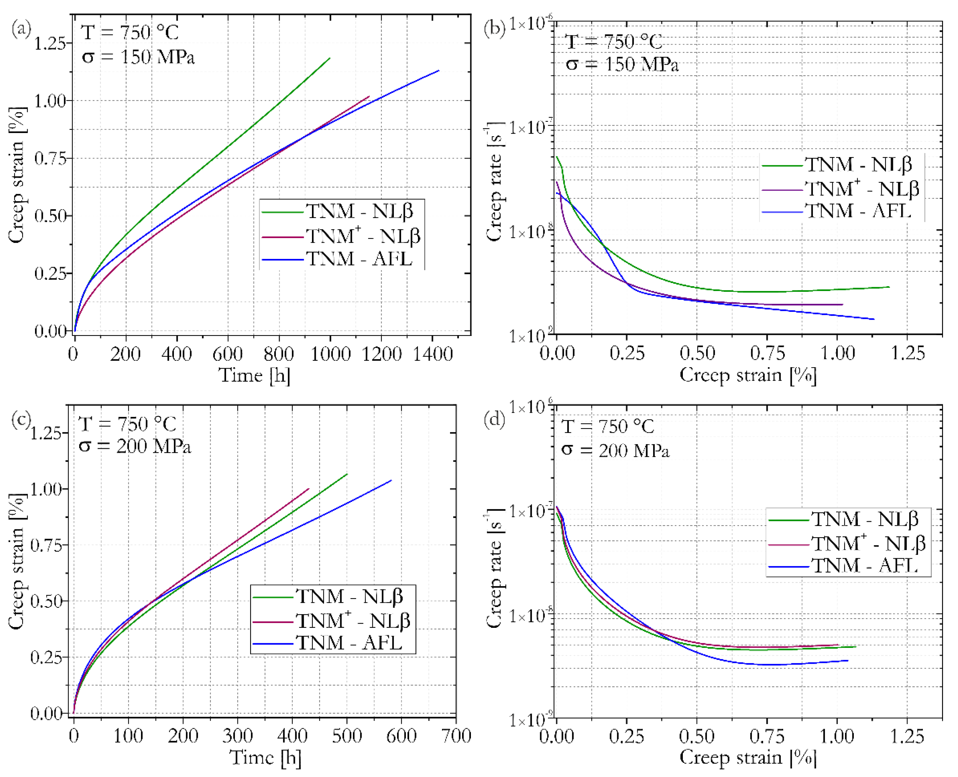
3.2. Creep Properties of LPBF Processed TNM and TNM+ Alloys

Because γ-TiAl-based alloys are considered as lightweight, high-temperature materials, the creep properties of heat-treated LPBF-TNM/TNM+ specimens were investigated. The results of creep tests are shown in Figure 8, where NLβ microstructures for the TNM and TNM+ alloy, which were obtained by heat treatment procedures 1 and 2, were compared to TNM specimens exhibiting a AFL microstructure according to procedure 4. Figure 8a depicts the creep strain over time for specimens tested at 750 °C and 150 MPa. The corresponding creep rates as a function of the creep strain are shown in Figure 8b. Whereas the TNM and TNM+ samples with NLβ microstructures already reached their respective minimal creep rate, the TNM specimen with AFL microstructure did not surpass the creep rate minimum yet, which proves its good creep capability. The most important results of these tests are also listed in Table 4, stating creep test time (tcreep), corresponding creep strain, minimal creep rate, as well as the time until 1% creep strain (t1%). All samples exhibited a creep strain below 1% after 500 h. The TNM alloy with the homogenized AFL microstructure after procedure 4 shows the best creep performance with a creep rate of 1.4 × 10⁻⁹ s−1 (although the minimal creep rate minimum had not yet been reached and is, therefore, even lower) and a t1% of 1174 h. TNM and TNM+ with NLβ microstructures also perform satisfactorily, with a minimal creep rate of 2.5 × 10⁻⁹ s−1 and a t1% of 811 h for the TNM alloy, and 1.9 × 10⁻⁹ s−1 and 1125 h for the TNM+ alloy. However, the AFL microstructure of the TNM specimen was capable of outperforming even the TNM+ alloy with NLβ microstructure, which points out the importance of adequate post-processing heat treatments.
The creep curves for an initial stress of 200 MPa tested at 750 °C are shown in Figure 8c. Again, the TNM specimen with the homogenized AFL microstructure revealed the best results (e.g., showing a t1% of 551 h) when compared to the TNM+ and TNM with NLβ microstructure with t1% of 429 and 461 h, respectively. The exact reason for the underperformance of the TNM+ alloy when tested at 750 °C and 200 MPa might be related to the LPBF fabrication of the specimen as well as slight differences in the NLβ microstructure, as an increased amount of βo-phase decreased creep performance as reported in [64]. The tested NLβ microstructure is overly sensitive to changes in chemistry, i.e., Al loss. Potentially, an increased Al loss compared to the other samples might be responsible for an increased amount of βo-phase, which, in turn, is responsible for poor creep performance. In this case, a remedy would be to lower the annealing temperature during the SHT. Furthermore, the addition and distribution of carbon might influence the creep properties. However, a full explanation is a topic of ongoing research.
All specimens reached a minimal creep rate when tested at 750 °C with 200 MPa (Figure 8d), with 3.1 × 10⁻⁹ s−1 for the AFL TNM alloy, 4.5 × 10⁻⁹ s−1 for the NLβ TNM specimen, and 4.8 × 10⁻⁹ s−1 for the NLβ TNM+ sample.
It is worth mentioning that the measured minimal creep rates, as well as the t1% values, are highly competitive. In fact, the measured values for the TNM specimen with an AFL microstructure processed by LPBF do surpass all those previously reported in [38] and in [65] for a wide variety of microstructures.

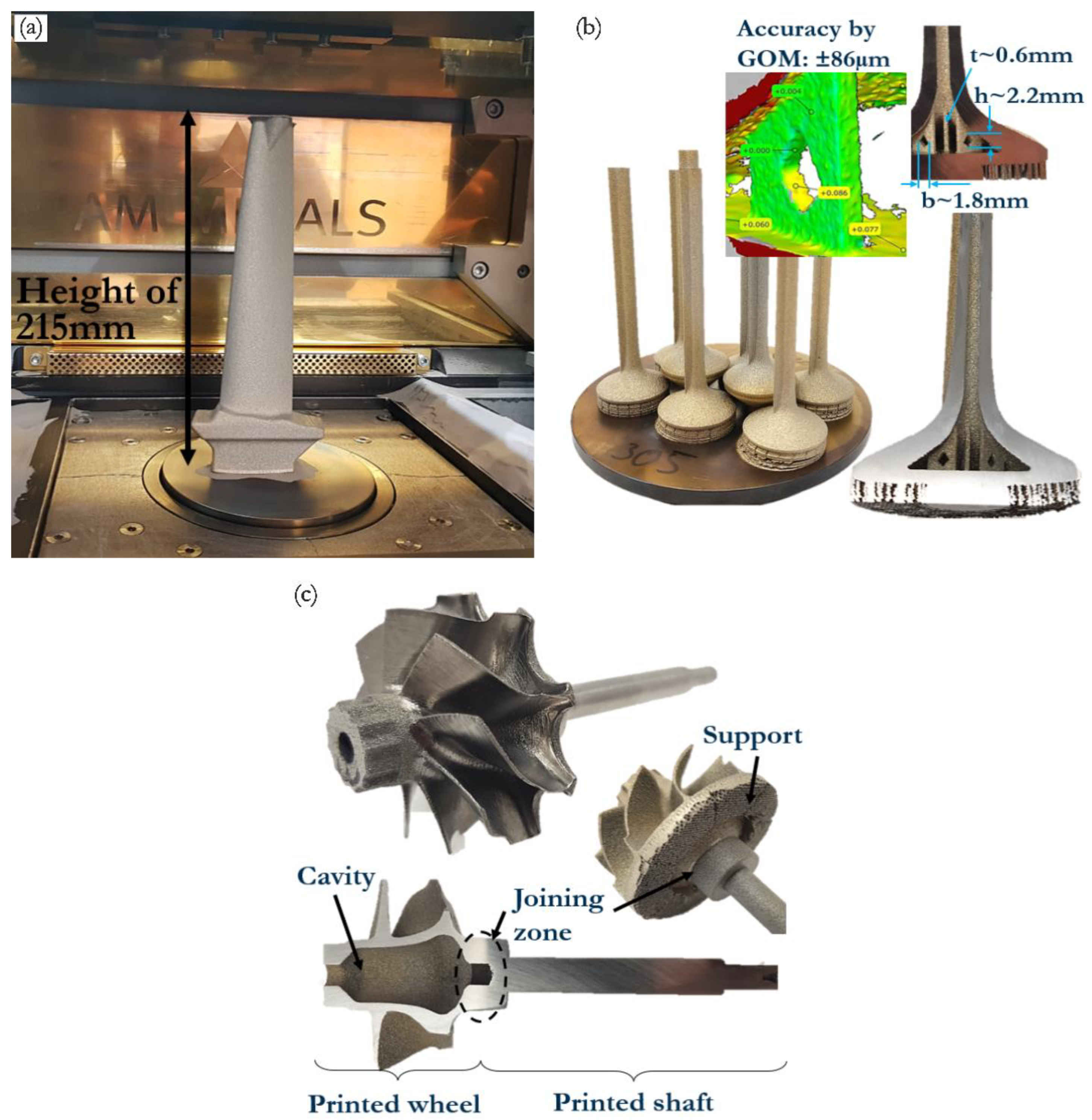
3.3. Feasibility of Laser Powder Bed Fusion of TNM Components

Intermetallic titanium aluminides based on the γ-TiAl phase have established themselves as materials for high-temperature applications where lightweight construction is required. Although it was established in the previous sections that microstructures with good creep properties can be obtained by LPBF, the capability to fabricate crack-free components of interest, such as turbine blades and valves, requires confirmation. The fabrication of such crack-free components made from a TiAl alloy in these dimensions was not possible before with LPBF. Therefore, the feasibility of the LPBF process to manufacture intermetallic TiAl components with complex geometries is demonstrated in this section. As established in this paper, the recently developed EOS-M290-HT unit can produce crack-free TiAl specimens. Currently, the industrial production of lightweight intermetallic TiAl alloys inlet and outlet valves, turbocharger turbine wheels, vanes and blades for aircraft engines are of interest as reported in [10,11,12,14,15,16]. Several of these components fabricated by means of this novel LPBF process employing TNM powder are shown in Figure 9.
Figure 9a shows a photograph of the process chamber of the EOS-M290-HT system showing a demonstrator aircraft engine LPT blade 21.5 cm high, manufactured in a 23-h build job. The build job and its conditions, such as the temperature field and the O level, are reproducible with maintained quality and can be confirmed by the logged data and subsequent chemical analysis.
Figure 9b shows the arrangement of eight TNM outlet valves exhibiting unique design features. As such, stacking components on top of each other can be used to increase the fill rate of the job and to position all parts in a way that guarantees optimal heating. In contrast to standard valve geometries, it is possible to realize valves showing inner cavities and filigree structures. The accuracy of less than ±90 µm of the filigree geometry features was established by geometrical optical measurements (GOM). The exemplary inner structure has a wall thickness of 0.6 mm and a diamond shape recess with a height of 2.2 mm and a width of 1.8 mm. All the powder can be removed from the cavities after the build job by a printed borehole with a diameter of 2 mm. An examination of such a TNM outlet valve, in as-built conditions, has shown a very homogeneous microstructure in all parts of the component. The density in the head and stem of the valve was above 99.91% and the maximum defect size was smaller than 50 µm.
Finally, Figure 9c displays a TNM turbocharger turbine wheel exhibiting a printed shaft that can be realized by a hybrid manufacturing technique. The initially manufactured shaft (which can either be a TNM alloy or a Ni-base alloy) is fixed in the base plate and heated up to process temperature. Subsequently, it is possible to print the wheel directly onto the cross-section of the shaft, where support structures underneath the wheel assist the fabrication process. The geometrical accuracy is good and a joining zone with excellent welding properties can be realized. The turbocharger wheel itself can be printed in a solid or hollow version with a great freedom of design.

4. Summary

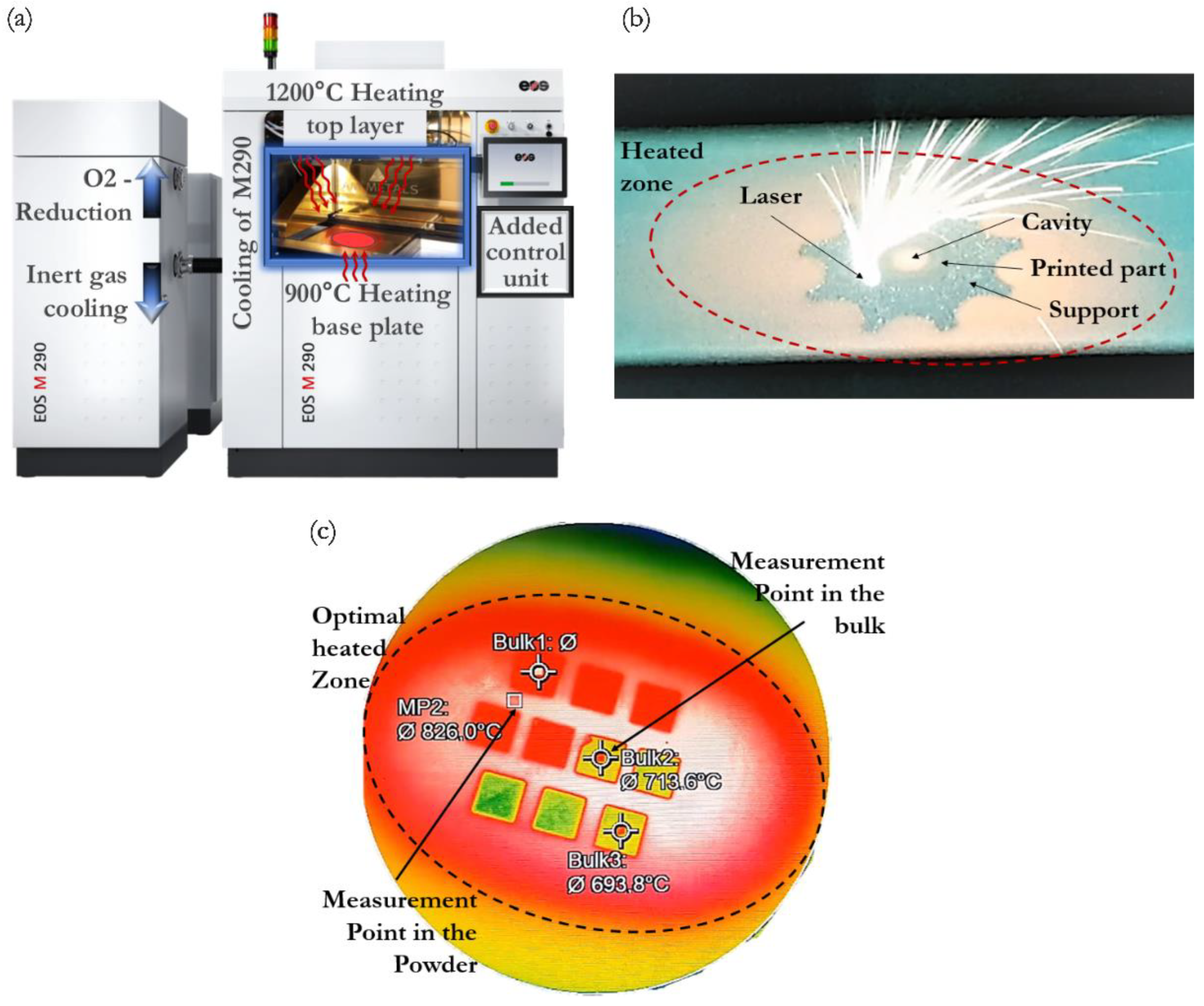
  • A novel laser powder bed fusion machine, which allows controlling the building temperature from the top of the manufactured part, was utilized to manufacture intermetallic TNM and TNM+ samples as well as demonstrator components. The evaporation-related loss of Al during the LPBF process was about 1 at.%.
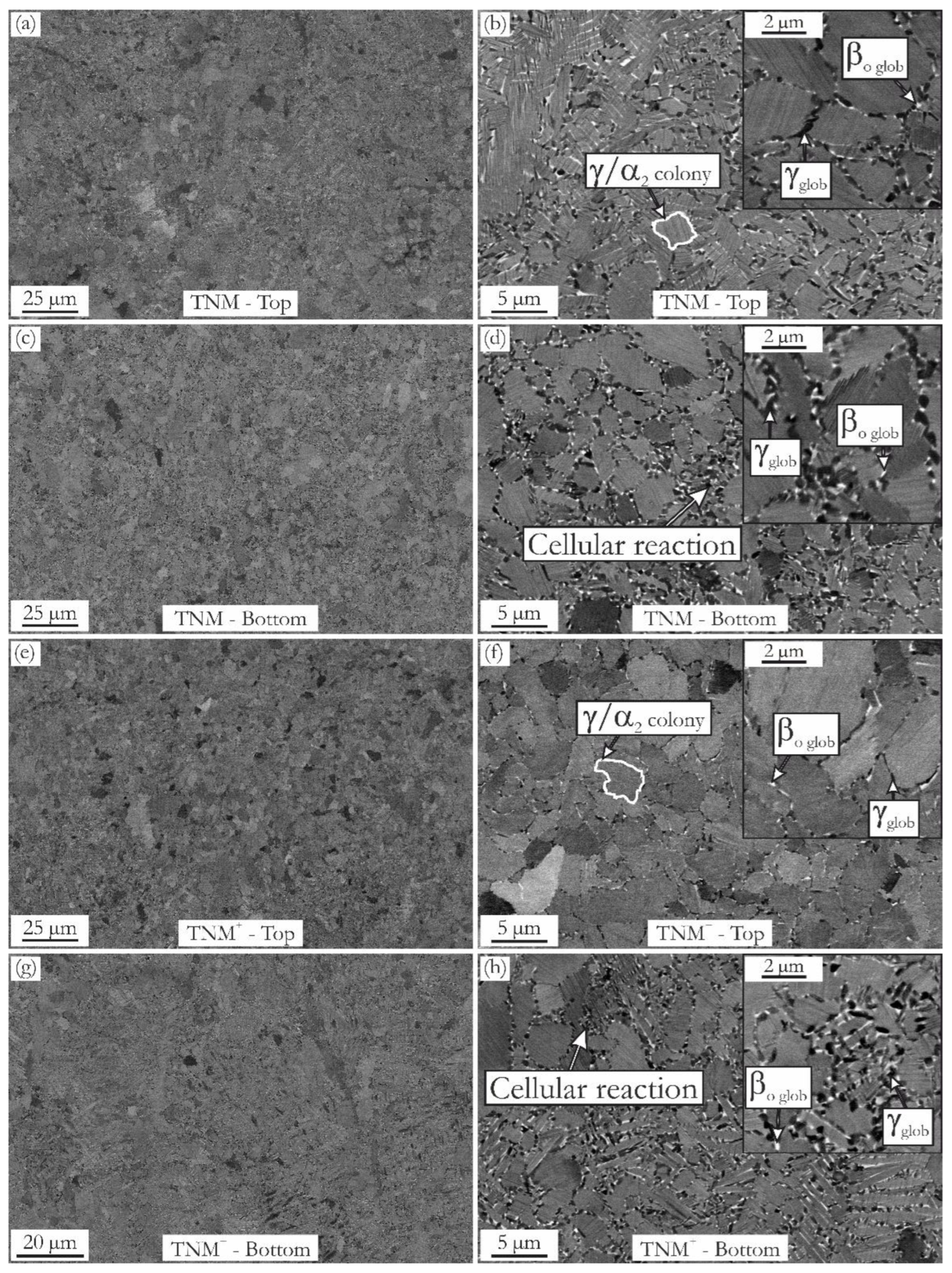
  • The microstructure of the samples in the as-built state consists of fine lamellar γ/α2-colonies with globular γ and βo grains situated at the colony boundaries. The amount of globular γ-grains and βo-phase increases from the last consolidated layers down to the base plate due to cellular reaction (discontinuous precipitation), which forms globular γ and βo at the expense of the γ/α2-colonies.
  • Investigating different build directions for LPBF-manufactured cylinders and barrel-vault geometry showed that the build height influences the phase fractions significantly, as a sufficient build height is necessary for the cellular reaction to take place due to the intrinsic long-term annealing during the process.
  • Lesser amounts of TIP could be detected within specimens that were heated above their respective HIP temperature during the subsequent pressureless heat treatments, but none for the specimens where the entire heat treatment procedure was performed in a HIP system, where until the end, a pressure of 150 MPa was maintained.
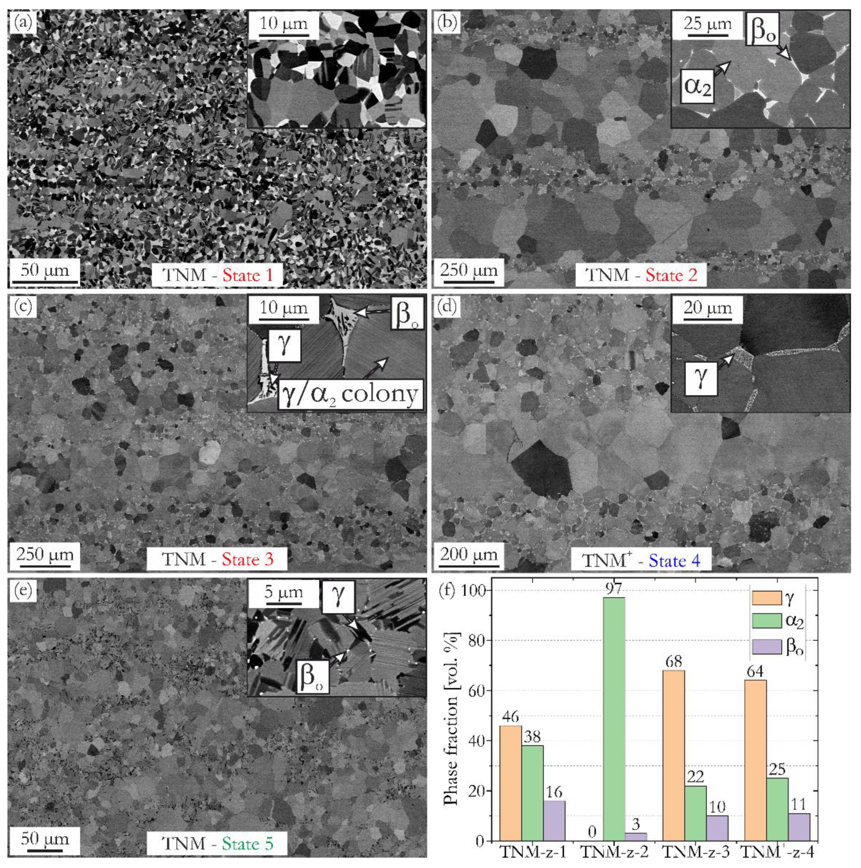
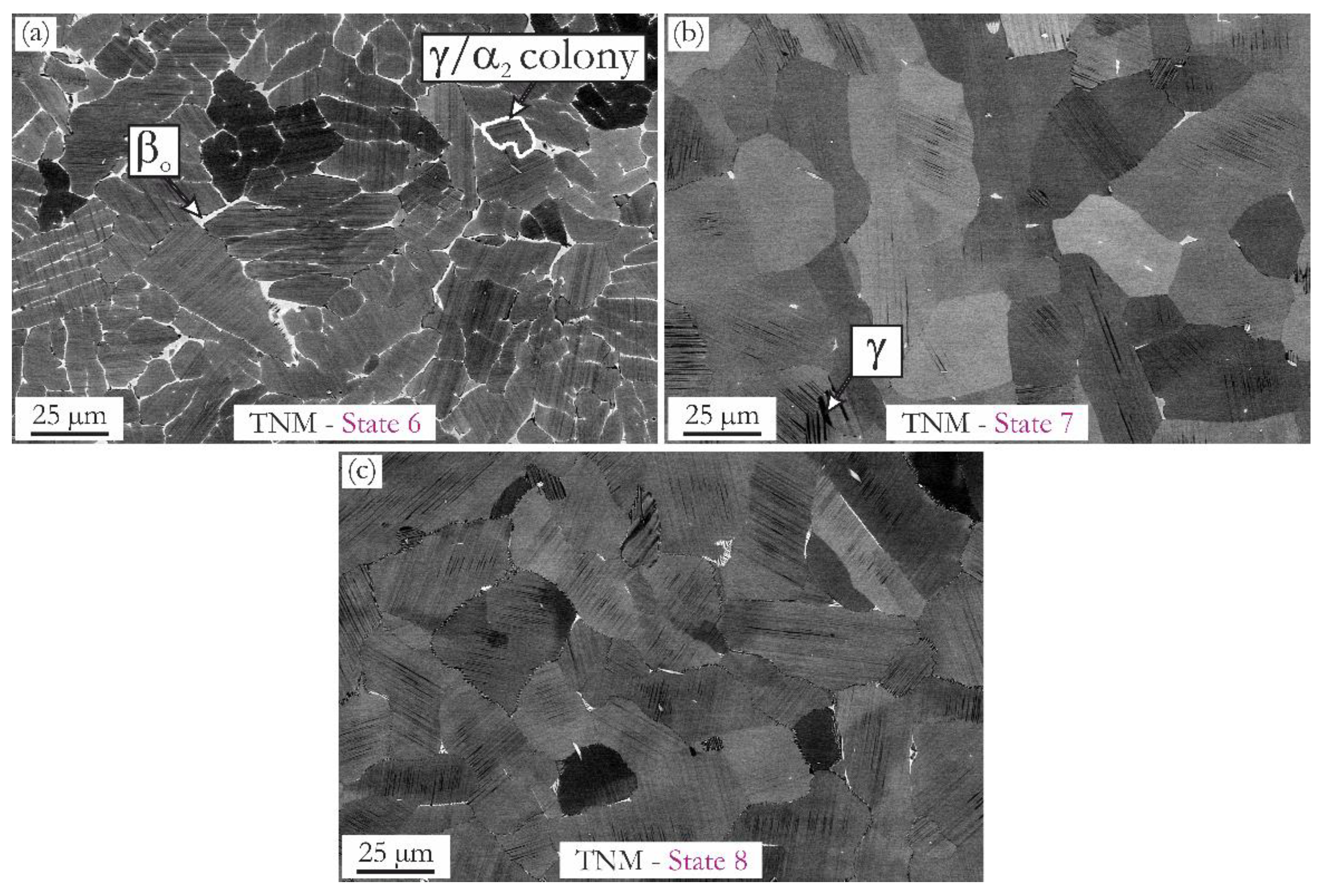
  • Sophisticated heat treatment procedures to adjust nearly lamellar β, nearly lamellar γ and almost fully lamellar microstructures were devised and realized. Due to microstructural heterogeneity related to the occurring loss of Al the TNM and TNM+ alloys are prone to form banded microstructures.
  • The almost fully lamellar microstructure of the TNM alloy revealed the best creep resistance at 750 °C for 150 MPa and 200 MPa, showing a minimal creep rate of 1.4 × 10⁻⁹ s−1 and 3.1 × 10⁻⁹ s−1, respectively.
  • Finally, demonstrator components with complex geometries, such as aero engine LPT blades, engine outlet valves with hollow features as well as turbocharger turbine wheels, were produced by the novel LPBF process using prealloyed TNM powder.

Author Contributions

Conceptualization, R.W. and H.C.; methodology, R.W.; software, not applicable; validation, R.W.; formal analysis, R.W.; investigation, R.W. and F.P.; resources, T.M.-I.; data curation, R.W.; writing—original draft preparation, R.W.; writing—review and editing, R.W., T.M.-I., F.P. and H.C.; visualization, R.W., T.M.-I. and F.P.; supervision, H.C.; project administration, H.C.; funding acquisition, not applicable. All authors have read and agreed to the published version of the manuscript.

Funding

Part of this research was supported by the EFRE and SAB in the project named HiPer-AM with the corresponding funding number 100298856.

Data Availability Statement

Not applicable.

Conflicts of Interest

The authors declare no conflict of interest.

References

  1. Kruth, J.-P.; Leu, M.C.; Nakagawa, T. Progress in Additive Manufacturing and Rapid Prototyping. CIRP Ann. 1998, 47, 525–540. [Google Scholar] [CrossRef]
  2. Calignano, F.; Manfredi, D.; Ambrosio, E.P.; Biamino, S.; Lombardi, M.; Atzeni, E.; Salmi, A.; Minetola, P.; Iuliano, L.; Fino, P. Overview on Additive Manufacturing Technologies. Proc. IEEE 2017, 105, 593–612. [Google Scholar] [CrossRef]
  3. Frazier, W.E. Metal Additive Manufacturing: A Review. J. Mater. Eng. Perform. 2014, 23, 1917–1928. [Google Scholar] [CrossRef]
  4. Thomas, M.; Malot, T.; Aubry, P.; Colin, C.; Vilaro, T.; Bertrand, P. The prospects for additive manufacturing of bulk TiAl alloy. Mater. High Temp. 2016, 33, 571–577. [Google Scholar] [CrossRef] [Green Version]
  5. Körner, C. Additive manufacturing of metallic components by selective electron beam melting—A review. Int. Mater. Rev. 2016, 61, 361–377. [Google Scholar] [CrossRef] [Green Version]
  6. Guo, N.; Leu, M.C. Additive manufacturing: Technology, applications and research needs. Front. Mech. Eng. 2013, 8, 215–243. [Google Scholar] [CrossRef]
  7. Löber, L.; Biamino, S.; Ackelid, U.; Sabbadini, S.; Epicoco, P.; Fino, P.; Eckert, J. Comparison of selective laser and electron beam melted titanium aluminides. In Proceedings of the 22nd International Solid Freeform Fabrication Symposium, Austin, TX, USA, 8–10 August 2011. [Google Scholar] [CrossRef]
  8. Dimiduk, D.M. Gamma titanium aluminide alloys—An assessment within the competition of aerospace structural materials. Mater. Sci. Eng. A 1999, 263, 281–288. [Google Scholar] [CrossRef]
  9. Lasalmonie, A. Intermetallics: Why is it so difficult to introduce them in gas turbine engines? Intermetallics 2006, 14, 1123–1129. [Google Scholar] [CrossRef]
  10. Kim, Y.-W.; Dimiduk, D.M. Progress in the Understanding of Gamma Titanium Aluminides. JOM 1991, 43, 40–47. [Google Scholar] [CrossRef]
  11. Clemens, H.; Mayer, S. Design, Processing, Microstructure, Properties, and Applications of Advanced Intermetallic TiAl Alloys. Adv. Eng. Mater. 2013, 15, 191–215. [Google Scholar] [CrossRef]
  12. Mayer, S.; Erdely, P.; Fischer, F.D.; Holec, D.; Kastenhuber, M.; Klein, T.; Clemens, H. Intermetallic β-Solidifying γ-TiAl Based Alloys—From Fundamental Research to Application. Adv. Eng. Mater. 2017, 19, 1600735. [Google Scholar] [CrossRef]
  13. Intergovernmental Panel on Climate Change (IPCC). Aviation and the Global Atmosphere; Penner, J.E., Lister, D.H., Griggs, D.J., Dokken, D.J., McFarland, M., Eds.; Cambridge University Press: Cambridge, UK, 1999. [Google Scholar]
  14. Bewlay, B.P.; Weimer, M.; Kelly, T.; Suzuki, A.; Subramanian, P.R. The Science, Technology, and Implementation of TiAl Alloys in Commercial Aircraft Engines. Mater. Res. Soc. Symp. Proc. 2013, 1516, 49–58. [Google Scholar] [CrossRef]
  15. Habel, U.; Heutling, F.; Kunze, C.; Smarsly, W.; Das, G.; Clemens, H. Forged Intermetallic γ-TiAl Based Alloy Low Pressure Turbine Blade in the Geared Turbofan. In Proceedings of the 13th World Conference on Titanium, San Diego, CA, USA, 16–20 August 2016. [Google Scholar] [CrossRef]
  16. Tetsui, T.; Shindo, K.; Kobayashi, S.; Takeyama, M. A newly developed hot worked TiAl alloy for blades and structural components. Scr. Mater. 2002, 47, 399–403. [Google Scholar] [CrossRef]
  17. Kastenhuber, M.; Rashkova, B.; Clemens, H.; Mayer, S. Enhancement of creep properties and microstructural stability of intermetallic β-solidifying γ-TiAl based alloys. Intermetallics 2015, 63, 19–26. [Google Scholar] [CrossRef]
  18. Wu, X. Review of alloy and process development of TiAl alloys. Intermetallics 2006, 14, 1114–1122. [Google Scholar] [CrossRef]
  19. Baudana, G.; Biamino, S.; Klöden, B.; Kirchner, A.; Weißgärber, T.; Kieback, B.; Pavese, M.; Ugues, D.; Fino, P.; Badini, C. Electron Beam Melting of Ti-48Al-2Nb-0.7Cr-0.3Si: Feasibility investigation. Intermetallics 2016, 73, 43–49. [Google Scholar] [CrossRef]
  20. Biamino, S.; Penna, A.; Ackelid, U.; Sabbadini, S.; Tassa, O.; Fino, P.; Pavese, M.; Gennaro, P.; Badini, C. Electron beam melting of Ti–48Al–2Cr–2Nb alloy: Microstructure and mechanical properties investigation. Intermetallics 2011, 19, 776–781. [Google Scholar] [CrossRef]
  21. Bewlay, B.P.; Nag, S.; Suzuki, A.; Weimer, M.J. TiAl alloys in commercial aircraft engines. Mater. High Temp. 2016, 33, 549–559. [Google Scholar] [CrossRef]
  22. Klassen, A.; Forster, V.E.; Juechter, V.; Körner, C. Numerical simulation of multi-component evaporation during selective electron beam melting of TiAl. J. Mater. Process. Technol. 2017, 247, 280–288. [Google Scholar] [CrossRef]
  23. Schwerdtfeger, J.; Körner, C. Selective electron beam melting of Ti–48Al–2Nb–2Cr: Microstructure and aluminium loss. Intermetallics 2014, 49, 29–35. [Google Scholar] [CrossRef]
  24. Seifi, M.; Salem, A.A.; Satko, D.P.; Ackelid, U.; Semiatin, S.L.; Lewandowski, J.J. Effects of HIP on microstructural heterogeneity, defect distribution and mechanical properties of additively manufactured EBM Ti-48Al-2Cr-2Nb. J. Alloys Compd. 2017, 729, 1118–1135. [Google Scholar] [CrossRef]
  25. Todai, M.; Nakano, T.; Liu, T.; Yasuda, H.Y.; Hagihara, K.; Cho, K.; Ueda, M.; Takeyama, M. Effect of building direction on the microstructure and tensile properties of Ti-48Al-2Cr-2Nb alloy additively manufactured by electron beam melting. Addit. Manuf. 2017, 13, 61–70. [Google Scholar] [CrossRef] [Green Version]
  26. Wartbichler, R.; Clemens, H.; Mayer, S.; Ghibaudo, C.; Rizza, G.; Galati, M.; Iuliano, L.; Biamino, S.; Ugues, D. On the Formation Mechanism of Banded Microstructures in Electron Beam Melted Ti–48Al–2Cr–2Nb and the Design of Heat Treatments as Remedial Action. Adv. Eng. Mater. 2021, 23, 2101199. [Google Scholar] [CrossRef]
  27. Wartbichler, R.; Bürstmayr, R.; Clemens, H.; Mayer, S. Selected Methods of Quantitative Phase Analysis of an Additively Manufactured TNM Titanium Aluminide Alloy. Pract. Metallogr. 2019, 56, 220–229. [Google Scholar] [CrossRef]
  28. Wartbichler, R.; Clemens, H.; Mayer, S. Electron Beam Melting of a β-Solidifying Intermetallic Titanium Aluminide Alloy. Adv. Eng. Mater. 2019, 21, 1900800. [Google Scholar] [CrossRef]
  29. Yap, C.Y.; Chua, C.K.; Dong, Z.L.; Liu, Z.H.; Zhang, D.Q.; Loh, L.E.; Sing, S.L. Review of selective laser melting: Materials and applications. Appl. Phys. Rev. 2015, 2, 41101. [Google Scholar] [CrossRef]
  30. Gussone, J.; Hagedorn, Y.-C.; Gherekhloo, H.; Kasperovich, G.; Merzouk, T.; Hausmann, J. Microstructure of γ-titanium aluminide processed by selective laser melting at elevated temperatures. Intermetallics 2015, 66, 133–140. [Google Scholar] [CrossRef]
  31. Mizuta, K.; Hijikata, Y.; Fujii, T.; Gokan, K.; Kakehi, K. Characterization of Ti-48Al-2Cr-2Nb built by selective laser melting. Scr. Mater. 2021, 203, 114107. [Google Scholar] [CrossRef]
  32. Löber, L.; Schimansky, F.P.; Kühn, U.; Pyczak, F.; Eckert, J. Selective laser melting of a beta-solidifying TNM-B1 titanium aluminide alloy. J. Mater. Process. Technol. 2014, 214, 1852–1860. [Google Scholar] [CrossRef] [Green Version]
  33. Soliman, H.A.; Yakout, M.; Elbestawi, M. Laser powder bed fusion of titanium aluminides using sequential thermal scanning strategy. J. Manuf. Processes 2022, 83, 438–457. [Google Scholar] [CrossRef]
  34. Doubenskaia, M.; Domashenkov, A.; Smurov, I.; Petrovskiy, P. Study of Selective Laser Melting of intermetallic TiAl powder using integral analysis. Int. J. Mach. Tools Manuf. 2018, 129, 1–14. [Google Scholar] [CrossRef]
  35. Schimbäck, D.; Braun, J.; Leichtfried, G.; Clemens, H.; Mayer, S. Laser powder bed fusion of an engineering intermetallic TiAl alloy. Mater. Des. 2021, 201, 109506. [Google Scholar] [CrossRef]
  36. Doubenskaia, M.; Grigoriev, S.; Zhirnov, I.; Smurov, I. Parametric analysis of SLM using comprehensive optical monitoring. Rapid Prototyp. J. 2016, 22, 40–50. [Google Scholar] [CrossRef]
  37. Gussone, J.; Garces, G.; Haubrich, J.; Stark, A.; Hagedorn, Y.-C.; Schell, N.; Requena, G. Microstructure stability of γ-TiAl produced by selective laser melting. Scr. Mater. 2017, 130, 110–113. [Google Scholar] [CrossRef]
  38. Schwaighofer, E.; Clemens, H.; Mayer, S.; Lindemann, J.; Klose, J.; Smarsly, W.; Güther, V. Microstructural design and mechanical properties of a cast and heat-treated intermetallic multi-phase γ-TiAl based alloy. Intermetallics 2014, 44, 128–140. [Google Scholar] [CrossRef]
  39. Clemens, H.; Kestler, H. Processing and Applications of Intermetallic γ-TiAl-Based Alloys. Adv. Eng. Mater. 2000, 2, 551–570. [Google Scholar] [CrossRef]
  40. Wegmann, G.; Gerling, R.; Schimansky, F.-P. Temperature induced porosity in hot isostatically pressed gamma titanium aluminide alloy powders. Acta Mater. 2003, 51, 741–752. [Google Scholar] [CrossRef]
  41. Tammas-Williams, S.; Withers, P.J.; Todd, I.; Prangnell, P.B. Porosity regrowth during heat treatment of hot isostatically pressed additively manufactured titanium components. Scr. Mater. 2016, 122, 72–76. [Google Scholar] [CrossRef]
  42. Li, W.; Liu, J.; Zhou, Y.; Li, S.; Wen, S.; Wei, Q.; Yan, C.; Shi, Y. Effect of laser scanning speed on a Ti-45Al-2Cr-5Nb alloy processed by selective laser melting: Microstructure, phase and mechanical properties. J. Alloys Compd. 2016, 688, 626–636. [Google Scholar] [CrossRef]
  43. Li, W.; Liu, J.; Zhou, Y.; Wen, S.; Tan, J.; Li, S.; Wei, Q.; Yan, C.; Shi, Y. Texture evolution, phase transformation mechanism and nanohardness of selective laser melted Ti-45Al-2Cr-5Nb alloy during multi-step heat treatment process. Intermetallics 2017, 85, 130–138. [Google Scholar] [CrossRef]
  44. Li, W.; Liu, J.; Zhou, Y.; Wen, S.; Wei, Q.; Yan, C.; Shi, Y. Effect of substrate preheating on the texture, phase and nanohardness of a Ti–45Al–2Cr–5Nb alloy processed by selective laser melting. Scr. Mater. 2016, 118, 13–18. [Google Scholar] [CrossRef]
  45. AM Metals Home Page. Available online: https://www.am-metals.de (accessed on 30 September 2022).
  46. EOS Home Page. Available online: https://www.eos.info/en (accessed on 30 September 2022).
  47. AMCM Home Page. Available online: https://amcm.com/ (accessed on 30 September 2022).
  48. Trumpf Vertical-Cavity Surface-Emitting Laser Solutions and Photodiodes Home Page. Available online: https://www.trumpf.com/en_US/products/vcsel-solutions-photodiodes/ (accessed on 30 September 2022).
  49. Gerling, R.; Clemens, H.; Schimansky, F.P. Powder Metallurgical Processing of Intermetallic Gamma Titanium Aluminides. Adv. Eng. Mater. 2004, 6, 23–38. [Google Scholar] [CrossRef]
  50. Fleißner-Rieger, C.; Pogrielz, T.; Obersteiner, D.; Pfeifer, T.; Clemens, H.; Mayer, S. An Additively Manufactured Titanium Alloy in the Focus of Metallography. Pract. Metallogr. 2021, 58, 4–31. [Google Scholar] [CrossRef]
  51. McCusker, L.B.; von Dreele, R.B.; Cox, D.E.; Louer, D.; Scardi, P. Rietveld refinement guidelines. J. Appl. Crystallogr. 1999, 32, 36–50. [Google Scholar] [CrossRef] [Green Version]
  52. Vyazovkin, S.; Burnham, A.K.; Criado, J.M.; Pérez-Maqueda, L.A.; Popescu, C.; Sbirrazzuoli, N. ICTAC Kinetics Committee recommendations for performing kinetic computations on thermal analysis data. Thermochim. Acta 2011, 520, 1–19. [Google Scholar] [CrossRef]
  53. Andersson, J.-O.; Helander, T.; Höglund, L.; Shi, P.; Sundman, B. Thermo-Calc & DICTRA, computational tools for materials science. Calphad 2002, 26, 273–312. [Google Scholar] [CrossRef]
  54. Yang, Y.; Chen, H.-L.; Chen, Q.; Engström, A. Development of CALPHAD database for both Ti- and TiAl-based alloys. MATEC Web Conf. 2020, 321, 12011. [Google Scholar] [CrossRef]
  55. Klein, T.; Rashkova, B.; Holec, D.; Clemens, H.; Mayer, S. Silicon distribution and silicide precipitation during annealing in an advanced multi-phase γ-TiAl based alloy. Acta Mater. 2016, 110, 236–245. [Google Scholar] [CrossRef]
  56. Clemens, H.; Mayer, S. Intermetallic Titanium Aluminides as Innovative High Temperature Lightweight Structural Materials—How Materialographic Methods Have Contributed to Their Development. Pract. Metallogr. 2015, 52, 691–721. [Google Scholar] [CrossRef]
  57. Scheu, C.; Stergar, E.; Schober, M.; Cha, L.; Clemens, H.; Bartels, A.; Schimansky, F.-P.; Cerezo, A. High carbon solubility in a γ-TiAl-based Ti–45Al–5Nb–0.5C alloy and its effect on hardening. Acta Mater. 2009, 57, 1504–1511. [Google Scholar] [CrossRef] [Green Version]
  58. Werner, R.; Schloffer, M.; Schwaighofer, E.; Clemens, H.; Mayer, S. Thermodynamic Calculations of Phase Equilibria and Phase Fractions of a β-Solidifying TiAl Alloy using the CALPHAD Approach. Mater. Res. Soc. Symp. Proc. 2012, 1516, 59–64. [Google Scholar] [CrossRef]
  59. Schmoelzer, T.; Liss, K.-D.; Zickler, G.A.; Watson, I.J.; Droessler, L.M.; Wallgram, W.; Buslaps, T.; Studer, A.; Clemens, H. Phase fractions, transition and ordering temperatures in TiAl–Nb–Mo alloys: An in- and ex-situ study. Intermetallics 2010, 18, 1544–1552. [Google Scholar] [CrossRef]
  60. Smith, C.S. Grains, Phases, and Interfaces: An Interpretation of Microstructure. Trans. Metall. Soc. AIME 1948, 175, 15–51. [Google Scholar]
  61. Hillert, M. On the theory of normal and abnormal grain growth. Acta Metall. 1965, 13, 227–238. [Google Scholar] [CrossRef]
  62. Filippini, M.; Beretta, S.; Içöz, C.; Patriarca, L. Effect of the Microstructure on the Fatigue Strength of a TiAl Intermetallic Alloy Produced by Additive Manufacturing. Mater. Res. Soc. Symp. Proc. 2015, 1760, 127–132. [Google Scholar] [CrossRef] [Green Version]
  63. Klein, T.; Niknafs, S.; Dippenaar, R.; Clemens, H.; Mayer, S. Grain Growth and β to α Transformation Behavior of a β-Solidifying TiAl Alloy. Adv. Eng. Mater. 2015, 17, 786–790. [Google Scholar] [CrossRef]
  64. Kastenhuber, M.; Klein, T.; Clemens, H.; Mayer, S. Tailoring microstructure and chemical composition of advanced γ-TiAl based alloys for improved creep resistance. Intermetallics 2018, 97, 27–33. [Google Scholar] [CrossRef]
  65. Wimler, D.; Lindemann, J.; Clemens, H.; Mayer, S. Microstructural Evolution and Mechanical Properties of an Advanced γ-TiAl Based Alloy Processed by Spark Plasma Sintering. Materials 2019, 12, 1523. [Google Scholar] [CrossRef]
Figure 1. (a) EOS-M290-HT system with base plate heating up to 900 °C; the uppermost powder bed layer can be heated up to 1200 °C; cooling system of the machine using inert gas; gas purification system for O2-level <200 m. ppm; additional control unit, sensors, IR camera and data logging; for further details, see text; (b) heated zone in the process chamber of the EOS-M290-HT, the manufactured turbocharger turbine wheel has a diameter of ~40 mm; (c) analyzed IR camera data in the heated zone of the EOS-M290-HT. The squares have a side length of 10 mm.
Metals 12 02087 g001
Figure 2. Schematic overview of the heat treatment studies conducted in this work, heat treatment procedures 1–4 (ad). The heading of each diagram also indicates the microstructures aimed for. Hot isostatic pressing (HIP) treatments are drawn in green color, solution heat treatments (SHT) are drawn in blue color, homogenization heat treatments (HHT) are drawn in red color and precipitation heat treatments (PHT) are shown in brown. In addition, the respective TγS is drawn as a horizontal line and several investigated microstructural states are marked with colored numbers.
Metals 12 02087 g002
Figure 3. SEM-BSE images of the as-built TNM and TNM+ specimens reveal the appearance of similar microstructures. Whereas the top regions (a,b,e,f) exhibit lamellar microstructures with small fractions of γglob and βo glob, the microstructures towards the bottom of the specimen (c,d,g,h) undergo a microstructural aging via a cellular reaction, thus transforming part of the lamellar colonies into γglob and βo glob. The microstructural constituents are marked in the micrographs, where βo appears very bright, γ shows a dark contrast and the α2/γ-lamellar colonies appear in an intermediate grey.
Metals 12 02087 g003
Figure 4. (a) Calculated phase fraction diagram for the actual chemistry of the fabricated TNM specimens (Table 1) by means of CALPHAD; (b) respective isopleth phase diagram for the Ti-Al-Nb-Mo system for the ratio Ti:Nb:Mo of 51.5:4.0:1.0. The nominal composition of 43.5 at.% is marked with a dashed vertical line and the actual composition is drawn as a green vertical line. The decrease of TβT and TγS is indicated by bold red lines.
Metals 12 02087 g004
Figure 5. Evolution of the microstructure of the TNM alloy during heat treatment procedure 1 (see Figure 2), (ac) represent states 1–3 as indicated in Figure 2a; (d) microstructure of the TNM+ alloy after procedure 2 (state 4); (e) microstructure of the TNM alloy after procedure 3 (state 5). The insets depict details of the microstructure (see text). All SEM images were taken in BSE mode; (f) phase fractions determined by means of XRD for the shown microstructures.
Metals 12 02087 g005
Figure 6. Schematic explanation of the formation of banded microstructures during a solution heat treatment of LPBF-TNM and LPBF-TNM+ specimens conducted in the proximity of TγS. The underlying heterogeneous Al-distribution due to Al evaporation leads to layered phase distributions of either γ (+β)-phase (SHT<TγS) or solely β-phase (SHT>TγS), inducing abnormal grain growth of the α-grains in those regions, where only a small amount of either γ (+β) or β as second-phase particles are present. Adjusting a “classic” FL microstructure is impossible for the TNM and TNM+ alloys as the alloys show no required α-single phase field region (see Figure 4). The building direction in this illustration is vertical.
Metals 12 02087 g006
Figure 7. SEM-BSE images showing the microstructural evolution of the LPBF-TNM alloy during the heat treatment procedure 4 to obtain an AFL microstructure; (ac) show the microstructure after the individual steps (states 6–8 as indicated in Figure 2d; see text for details). The building direction is vertical for all micrographs.
Metals 12 02087 g007
Figure 8. Creep results for the LPBF-TNM alloy with a NLβ and AFL microstructure, as well as the TNM+ alloy with a NLβ microstructure tested at 750 °C: (a) creep strain over time for an initial stress of 150 MPa; (b) creep rate over creep strain tested with 150 MPa; (c) creep strain over time for 200 MPa; (d) creep rate over creep strain for 200 MPa.
Metals 12 02087 g008
Figure 9. (a) Demonstrator aero engine LPT blade made from TNM alloy powder in the process chamber of an EOS-M290-HT LPBF machine; (b) base plate with eight fabricated TNM outlet valves in a solid or hollow version along with descriptions of geometrical features. The head of the valve has a diameter of ~30 mm and the stem exhibits an outer diameter of 5.5 mm and a length of 90 mm; (c) exemplary turbocharger turbine wheel, which was directly printed on the shaft using hybrid manufacturing technology with a cavity in the wheel as can be seen in the cross-sectional cut. The diameter of the wheel is ~40 mm and the shaft length is ~80 mm.
Metals 12 02087 g009
Table 1. Chemical composition of the feedstock powder and the LPBF-fabricated specimens of the TNM and TNM+ alloy in at.% and m. ppm, respectively (see text).
DesignationTi
[at.%]
Al
[at.%]
Nb
[at.%]
Mo
[at.%]
B
[at.%]
C
[at.%]
Si
[at.%]
O
[m. ppm]
N
[m. ppm]
TNM powderbal43.653.941.010.11--800–1000 *60
TNM+ powderbal42.754.001.030.11--820550
TNM as-builtbal42.743.971.020.100.320.3687070
TNM+ as-builtbal41.664.121.020.110.410.38870360
* 800–1000 m. ppm oxygen was measured across different batches and sample extraction sites.
Table 2. Phase fractions established by XRD for the TNM and TNM+ alloys and the relative density ρrel in the as-built condition.
Designationα2
[vol.%]
βo
[vol.%]
γ
[vol.%]
ρrel
[%]
TNM z2896399.85
TNM+ z3186199.97
TNM+ 45°3276199.93
TNM+ xy4864699.97
Table 3. Phase fractions established by XRD for the TNM alloy (state 1, 2 and 3) as well as the TNM+ alloy (for the three different geometries z, 45° and xy, in state 4) after procedure 1 and 2 (see Figure 2a,b). In addition, the relative density ρrel and the Vickers hardness are given.
Designationα2
[vol.%]
βo
[vol.%]
γ
[vol.%]
ρrel
[%]
HV10
TNM state 1—z 381646100395
TNM state 2—z973099.98434
TNM state 3—z22106899.99460
TNM+ state 4—z251164100499
TNM+ state 4—45°251164100490
TNM+ state 4—xy251263100492
Table 4. Results of creep tests conducted on LPBF-TNM and TNM+ alloys after adjustment of the indicated microstructures.
DesignationCreep Parameters
[°C/MPa]
tcreep
[h]
εmax at tcreep
[%]
Minimal Creep Rate
[s−1]
t1%
[h]
TNM NLβ750 °C/150 MPa9981.172.5 × 10−9811
TNM NLβ750 °C/200 MPa5001.064.5 × 10−9461
TNM+ NLβ750 °C/150 MPa11521.021.9 × 10−91125
TNM+ NLβ750 °C/200 MPa4301.004.8 × 10−9429
TNM AFL750 °C/150 MPa14241.14* 1.4 × 10−91174
TNM AFL750 °C/200 MPa5811.043.1 × 10−9551
* Minimal creep rate not yet reached.
Publisher’s Note: MDPI stays neutral with regard to jurisdictional claims in published maps and institutional affiliations.

