Abstract
Mold design is one of the important ways to control shrinkage porosity. In this study, four mold forms with different tapers were first designed, the corresponding three-dimensional finite element models were built using the ProCAST software, and the influence of mold design on the filling and solidification processes of Ti-6Al-4V alloy was investigated. The results showed that the titanium alloy ingots exhibit typical characteristics of layer-by-layer solidification, and that the removal of the riser results in: (a) shortening the time it takes for molten metal to reach the bottom of the mold and the time needed to complete mold filling; (b) decreasing the maximum flow velocity and improving the filling stability; and (c) moving the shrinkage cavities up along the central axis of the ingot and decreasing the cavity volume. Meanwhile, it was also found that the shrinkage cavity volume decreases significantly with increasing mold taper, meaning a significant increase in ingot utilization rate. The shrinkage cavity formation mechanism was revealed through macrostructure analysis. During solidification, a grain frame is formed as a large number of equiaxed crystals intersect, thus creating an isolated liquid phase zone. When the liquid in this zone solidifies, the last zone to do so, its volume shrinkage cannot be compensated, thus leading to the formation of a shrinkage cavity.
1. Introduction
Ti-6Al-4V (wt.%) alloy has been widely applied in aerospace, ocean engineering, biomedicine, and other fields owing to its good comprehensive mechanical properties and low production costs [1,2]. However, the defect of shrinkage porosity in Ti-6Al-4V alloy castings seriously reduces the serviceability of the alloy products and reduces the material utilization rate [3]. At present, researchers use various methods to control the formation of shrinkage cavities, including the hot isostatic pressing technique [3,4,5], optimizing the smelting method [6,7,8,9,10,11] and improving the casting process [12,13,14,15,16], and certain positive results have been achieved.
Research shows that the use of the hot isostatic pressing technique can effectively reduce shrinkage porosity in titanium alloy castings. Atkinson et al. [4] demonstrated clearly that reducing shrinkage porosity in as-cast microstructure is one of the main benefits of the hot isostatic pressing technique. Feng et al. [3] investigated the influence of the hot isostatic pressing technique on the shrinkage porosity of large, thin-walled Ti-6Al-4V alloy castings, finding that the method can not only effectively suppress the formation of shrinkage cavities, but can also significantly improve the bonding force of β grain boundaries, thus improving the toughness of the castings. However, the hot isostatic pressing process causes dimensional deformation of castings, and using the method it is difficult to eliminate shrinkage porosity completely [8,17,18,19]. With the continuous progress in casting technology in recent years, advanced processes such as centrifugal casting [6,7,8], anti-gravity casting [9,10], and vacuum suction casting [11] have been widely used in the preparation of titanium alloy castings. Yang et al. [6] compared the effects of centrifugal and gravity casting on the shrinkage porosity of TiAl alloy castings by means of numerical simulation and experimental verification. The results show that centrifugal casting is more effective at suppressing the formation of isolated liquid phase zones and at reducing the volume of the shrinkage cavity. Suzuki et al. [7] investigated the effect of centrifugal speed on the shrinkage porosity of Ti-6Al-4V alloy castings, revealing that increasing centrifugal speed can effectively suppress the formation of shrinkage cavities. However, when the centrifugal speed is too high, the flow of molten metal may stop, resulting in the formation of shrinkage cavities [8]. In their study on the anti-gravity casting process of Ti-6Al-4V alloy, Ma et al. [9] clearly illustrated that the formation of shrinkage cavities can be effectively controlled by improving mold filling and adopting pressurized solidification. By examining the effect of filling pressure on the shrinkage porosity of TiAl alloy during anti-gravity casting, Yang et al. [10] clarified that increasing filling pressure can significantly increase the fluidity of molten metal and reduce heat loss, helping to suppress the formation of pre-solidification zones and effectively improve the feeding capacity of the molten metal. However, excessively high filling pressure is not conducive to the control of shrinkage porosity. It is worth noting that proper design of the casting process, such as setting a suitable pouring temperature and mold preheating temperature, is always important in reducing shrinkage porosity. Research shows [12,13,14,15,16] that these factors can effectively improve the fluidity of the molten metal and reduce heat loss, ensuring the high feeding capacity of the molten metal and suppressing the formation of shrinkage cavities. In addition, Gao et al. [20] significantly reduced the shrinkage cavity volume in a TiAl alloy ingot by adding a temperature gradient to the mold, pioneering a new path for controlling shrinkage porosity in titanium alloy ingots.
Unfortunately, relatively little effort has been made to study the influence of mold design on the shrinkage porosity of titanium alloy castings. In this study, the influence of mold design on the shrinkage porosity of Ti-6Al-4V alloy ingots was systematically investigated using four casting mold forms with slightly different shapes. Adopting an approach combining numerical simulation and experimental verification, the influence of a riser on alloy filling and solidification processes was studied, the quantitative relationship between the mold taper and shrinkage cavity (including shrinkage cavity volume and material utilization rate) was analyzed in depth, and the formation mechanism of shrinkage cavities in titanium alloy ingots was elucidated, thus providing an effective way to control shrinkage porosity in titanium alloy ingots.
2. Materials and Methods
2.1. Finite Element Model
In this study, the casting process of Ti-6Al-4V (wt.%) alloy was systematically explored using the ProCAST 2018software (ESI Group, Paris, France). First, four common mold forms I–IV were designed (Figure 1) based on the casting equipment available, and the sample ingots prepared with the four mold forms were named alloys I–IV, respectively. Mold I features a riser with a height of 50 mm, and molds II–IV have no risers. The four ingots and molds have relative mass ratios of 0.56, 0.51, 0.55, and 0.47. Then, the sample ingots and molds were modeled in three dimensions and partitioned into meshes. The mesh of each ingot has an average cell size of 5 mm to ensure that there are at least two meshes at the thinnest part of the ingots, the mesh of each mold has an average cell size of 10 mm, and the number of volume mesh cells is about 334,737.
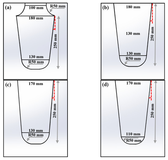
Figure 1.
Mold design: (a) mold I; (b) mold II; (c) mold III; (d) mold IV.
2.2. Thermophysical Parameters and Boundary Conditions
Ti-6Al-4V alloy was chosen as the material for preparing the ingots and graphite was used as the mold material. The liquidus and solidus temperatures of Ti-6Al-4V alloy are 1660 °C and 1604 °C, respectively [5], and other thermophysical parameters were calculated using the ProCAST software, as shown in Table 1. Graphite has a density of 1690–1720 kg·m−3, a specific heat capacity of 0.72–2.89 kJ·kg−1·K−1, and a thermal conductivity of 12–108 W·m−1·K−1. In the calculation process, the pouring temperature was set to 1700 °C, the mold preheating temperature was 300 °C, and the pouring speed was 4.7 kg·s−1. Meanwhile, the stress type of the Ti-6Al-4V alloy was set to “linear-elastic”, the stress type of graphite was “rigid”, and the cooling method was “air cooling”, with a heat transfer coefficient between the casting and the mold shell of 800 W·m−2·K−1.

Table 1.
Physical parameters of Ti-6Al-4V based on ProCAST calculation.
In this study, the flowing molten metal was regarded as an incompressible Newtonian fluid, and the governing Equations (1)–(5) in the process of mold filling and solidification are as follows [6,10,21]:
The Navier-Stokes equations for viscous fluids are [6,21]:
Continuity equation [10,21]:
Heat conduction equation [10,21]:
where, ρ is the density of the molten metal; u, v, and w are the velocity vectors in the directions of x, y, and z respectively; P is pressure; g is the gravitational acceleration; μ is the viscosity; t is time; Cp is the specific heat capacity; T is the temperature; λ is the thermal conductivity coefficient; L is the latent heat of crystallization, and fs is the solid fraction in the solidification stage.
2.3. Ingot Preparation and Macrostructure Characterization
Titanium alloy ingots weighing 20 kg each were prepared using a vacuum induction melting furnace. The raw materials include sponge titanium, pure Al, and Al-V alloy (V: 58.18wt.%). The iCAP 7400 ICP-OES analyzer (Thermo, Waltham, MA, USA) and the TCH600 N, H, and O analyzer (LECO, St. Joseph, MI, USA) were used to analyze the main elements (Al and V) and impurity elements (N, H, and O) of the ingots, respectively. The above test samples were all φ4 × 10 mm discs weighing less than 30 mg, which were mechanically ground and ultrasonically cleaned in alcohol for 10 min. For each ingot, at least three positions were chosen for analysis, and the results are displayed in Table 2 to guarantee the correctness of the test results. Then, the ingots were dissected along the center line to show the distribution of shrinkage cavities. Meanwhile, the as-cast macrostructure of each ingot was observed. The metallographic etching solution used in the observation was Kroll reagent (5% HF + 10% HNO3 + 85% H2O).
Table 2.
Measured chemical compositions (wt.%) of the Ti-6Al-4V.
3. Results
3.1. Numerical Simulation of Mold I
Figure 2 shows the filling process and the flow velocity of molten metal when mold I is used. At 0.24 s, the molten metal quickly reached the bottom of the mold under the action of gravity (Figure 2a), and the mold was completely filled at 4.09 s, with a filling rate of 98vol.% (Figure 2e). At the initial stage of mold filling, the molten metal has a high flow velocity (2.394 m·s−1) and an obvious velocity gradient in the height direction (Figure 2g,h), but the mold filling stability is poor, which can easily lead to gas entrapment and molten metal splashing at the bottom of the mold. Xiong et al. [11] studied the influence of filling speed on the filling process of a TiAl alloy exhaust valve, reaching the following two conclusions. (1) A high filling speed causes a violent collision between the molten metal and the sprue, leading to the splashing of the molten metal. (2) A high filling speed causes serious turbulence at the surface of the molten metal, resulting in the entrapment of a large amount of gas. Liu et al. [22] also found in the investment casting process of a ZG310-570 steel bracket that an increase in filling speed significantly increases the probability of gas entrapment at the bottom of the casting. As the mold filling process progresses, the filling speed decreases obviously, the speed gradient weakens significantly, and the mold filling process stabilizes gradually (Figure 2d,i). At the late filling stage, the speed gradient disappears completely, and the filling proceeds stably (Figure 2j).
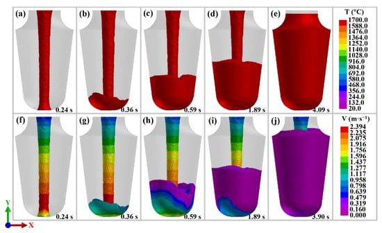
Figure 2.
Filling process (a–e) and fluid velocity (f–j) of Ti-6Al-4V alloy in mold I.
Figure 3 shows the solidification process of molten metal and the distribution of shrinkage cavities when mold I is used. It can be seen from Figure 3a that at 1.13 s the part of the molten metal in contact with the mold wall solidifies first. As the mold-filling process progresses, the solidification zone gradually expands along the mold wall (the expansion direction is indicated by the gray arrow in Figure 3b). At 9.12 s, the part close to the mold wall approaches complete solidification (Figure 3c). This phenomenon further proves that the heat radiation of molten metal along the vertical wall is faster than in other directions. As the solidification process progresses, the part of the molten metal at the riser area reaches complete solidification first (Figure 3d), which means that the riser designed in this study cannot effectively fulfill the purpose of feeding. Meanwhile, the bottom part of the alloy ingot (where the cross-sectional area is smaller), under conditions of relatively good heat dissipation, reaches complete solidification earlier than the top part of the alloy ingot (where the cross-sectional area is larger). This leads to the formation of an isolated liquid phase zone at the central region of the top part of the alloy ingot, as shown in Figure 3e. Generally speaking, titanium alloy ingots exhibit typical characteristics of layer-by-layer solidification. It can be seen from Figure 3f that the shrinkage cavities are concentrated at the top part of the ingot, with a volume of 3.29 cm3, and the ingot utilization rate is 63.6% (where ingot utilization rate = the distance between the shrinkage cavity and the bottom of the ingot/mold height × 100%, and mold height = ingot height + riser height). It is worth noting that the zone of the shrinkage cavity almost completely coincides with the isolated liquid phase zone. Therefore, it can be concluded that the formation of the shrinkage cavity is closely related to the formation of the isolated liquid phase zone. The formation mechanism of the isolated liquid phase zone will be analyzed in detail later in this article.
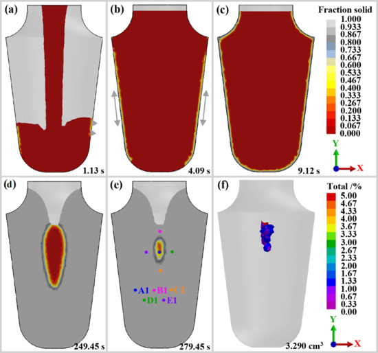
Figure 3.
Solidification process (a–e) and shrinkage porosity (f) of Ti-6Al-4V alloy in mold I.
3.2. Numerical Simulation of Molds II, III, and IV
Mold I was optimized based on the above simulation results. Usually, to achieve proper feeding, the riser design can be optimized to ensure that it solidifies later than the casting. However, the use of a riser will significantly reduce the ingot utilization rate, especially when the mass of the ingot is small. Therefore, the riser in mold I was removed, resulting in mold II (Figure 1b). Figure 4a–e shows the mold filling process when mold II is used. It can be seen that when mold II is used, the molding filling has characteristics similar to those of mold I, but the bottom-reaching time of molten metal and filling time are shortened to 0.23 s and 3.57 s, respectively. As can be seen from the simulation results of molten metal flow velocity, Figure 5a–e, the maximum flow velocity of the molten metal decreases to 2.228 m·s−1 and the speed gradient difference at the initial stage of mold filling decreases, indicating that the mold II filling process is more stable than that of mold I. As demonstrated by the solidification process simulation results in Figure 6a–e, switching from mold I to mold II results in the formation position of the isolated liquid phase zone moving towards the top of the ingot along the central line. This is a desirable result. Figure 7a further proves that the use of mold II can not only effectively suppress the formation of shrinkage cavities (alloy II: 0.061 cm3) but can also move the shrinkage cavity formation position towards the top of the ingot along the central line. In alloy I, the shrinkage cavity is 46.8 mm from the top of the ingot, while this distance is shortened to 34.1 mm in alloy II, increasing the utilization rate of ingot II to 86.4%.
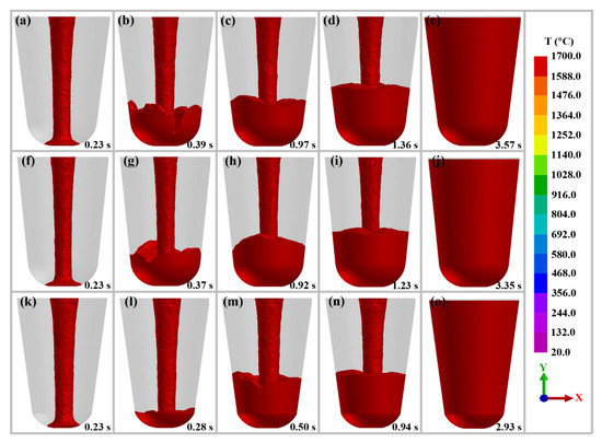
Figure 4.
Filling process of Ti-6Al-4V alloy in mold II (a–e), III (f–j), and IV (k–o).
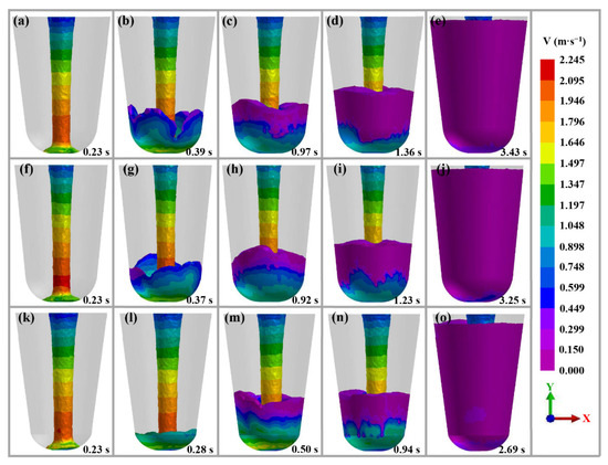
Figure 5.
The fluid velocity of Ti-6Al-4V alloy in mold II (a–e), III (f–j), and IV (k–o).
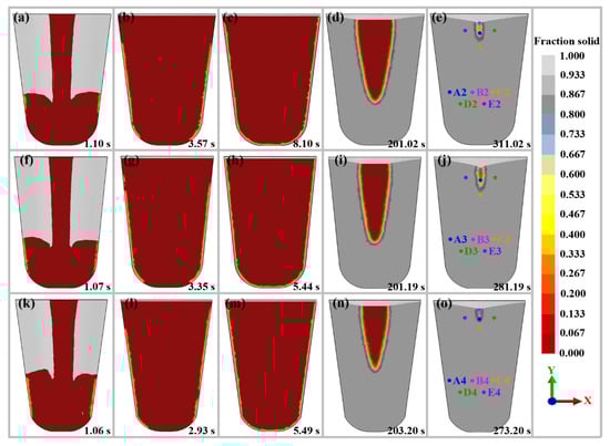
Figure 6.
Solidification process of Ti-6Al-4V alloy in mold II (a–e), III (f–j), and IV (k–o).
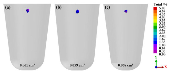
Figure 7.
Distribution of shrinkage porosity for Ti-6Al-4V alloy in mold II–IV: (a) II; (b) III; (c) IV.
To further improve the mold filling and alloy casting solidification processes, an in-depth investigation on the key parameters of mold II was carried out, designing molds III and IV as shown in Figure 1c,d. The design of mold III reduces the top size of the ingot to 170 mm, and the design of mold IV reduces the bottom size of the ingot to 110 mm (smaller than mold III). It can be seen from Figure 4f–j and Figure 5f–j that, when mold III is used, the molding filling has characteristics similar to those of mold II, but the maximum flow velocity of molten metal is slightly increased (2.245 m·s−1). It can be seen from Figure 6f–j that, when mold III is used, the ingot solidification process exhibits no unique characteristics and that the shrinkage cavity volume is basically unchanged (0.059 cm3), but that the ingot utilization rate is reduced to 85.8% (Figure 7b). It is worth noting that reducing the bottom size of the ingot lowers the maximum flow velocity of molten metal to 2.198 m·s−1, thus promoting smooth mold filling, as shown in Figure 4k–o and Figure 5k–o. At the same time, this change has no obvious impact on shrinkage cavity volume (0.058 cm3) and ingot utilization rate (86.7%), as shown in Figure 7c.
3.3. Experimental Verification
Figure 8 shows the Ti-6Al-4V alloy ingots prepared using molds I–IV. It can be seen that the actual distribution and volume variation pattern of shrinkage cavities in ingots I–IV are basically consistent with the simulation results. However, ingot I contains a large number of small shrinkage cavities and the riser can play a few roles in feeding. Ingot IV contains a small number of small shrinkage cavities. In order to visualize the morphology and distribution of the small shrinkage cavities, the blue rectangular boxed area in Figure 8a is enlarged appropriately and its important features are drawn at a certain scale, as shown in Figure 8b,c. The large shrinkage cavity is represented by the blue region, while the small shrinkage cavity is represented by the orange area. The statistical results show that ingot I has four large shrinkage cavities with an aspect ratio of 1.2–2.0 and nearly 100 small shrinkage cavities with a length of 0.37–2.94 mm that are concentrated around the large shrinkage cavities; in contrast, ingot IV has two large shrinkage cavities with an aspect ratio of 1.1 or 1.4 and a significantly smaller number (about 30) of small shrinkage cavities with a length of 0.5–1.94 mm. Noticeably, the utilization rates of ingots I–IV are 60.5%, 73.6%, 74.5%, and 80.5%, respectively, slightly different from the simulation results. Nonetheless, these figures prove that a rational mold design can effectively improve the material utilization rate. On the whole, numerical simulation results can provide some guidance for controlling the shrinkage porosity of titanium alloy ingots.
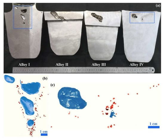
Figure 8.
Shrinkage porosity of actual ingots (a) and local enlargement of ingot I (b) and IV (c).
4. Discussion
4.1. Formation Mechanism of Shrinkage Porosity
It can be seen from Figure 3, Figure 6, and Figure 7 that, at the initial stage of solidification, the molten metal solidifies layer by layer from the mold wall to the center of the ingot. The areas with good heat dissipation, such as the bottom of the ingot (where the cross-sectional area is relatively small), solidify first to form a solid surface layer. As the solidification process progresses, the solid shrinkage in the solidified area, the solidification shrinkage caused by solidification, and the liquid shrinkage in the core of the ingot caused by the temperature decrease occur simultaneously. At the late stage of solidification, an isolated liquid phase zone gradually forms in the top central part of the ingot (the area with a larger cross-sectional area). When the sum of the liquid shrinkage and solidification shrinkage of the alloy is greater than the solid shrinkage, a shrinkage cavity will be formed in this area.
Zhang et al. [9] studied the anti-gravity casting process of Ti-6Al-4V alloy and discovered, through numerical simulation and experiment, that shrinkage cavities mostly occur in areas with relatively large cross sections, and that their locations are close to the sprue and riser. This is mainly because the area with a large cross-sectional area can better preserve heat. When other areas are completely solidified, cutting off the feeding channel, an isolated liquid phase zone will be formed in this area [11]. By studying the influence of TiB2 on the fluidity of TiAl alloy, Han et al. [23] revealed that shrinkage cavities usually occur in the area that is the last part to solidify. In other words, at the late stage of solidification, the temperature of the isolated liquid phase zone is higher than its surrounding area. For each ingot, five points (A, B, C, D, and E) in the isolated liquid phase zone and the surrounding areas (Figure 3e and Figure 6e,j,o) were picked, and the temperature variation of each point with time was analyzed. The results are shown in Figure 9. As the solidification process progresses, the temperature of point A gradually becomes higher than those of points B, C, D, and E, indicating that these solidify earlier than point A. This means that an isolated liquid phase region will be formed at point A and a shrinkage cavity will be formed at this location. In the same way, Yang et al. [24] explored the formation mechanism of shrinkage cavities in the casting process of TiAl alloy blades, finding that the formation of a shrinkage cavity is related to the presence of an isolated liquid phase zone (in the central region of the blade with larger thickness), and that the temperature of this zone was significantly higher than its surrounding area. Similarly, this formation mechanism was also discovered by Zheng et al. [25] in a study on the vacuum casting process of a brake drum made of Al-based composite materials.
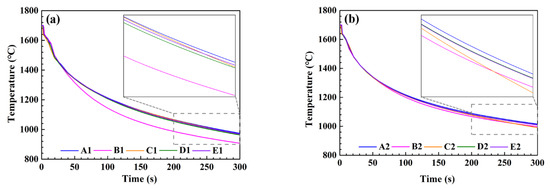
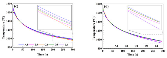
Figure 9.
Temperature variation in the isolated liquid phase zones and their surrounding areas: (a) alloy I; (b) alloy II; (c) alloy III; (d) alloy IV.
Research shows [26] that the termination of melt metal flow of Ti-6Al-4V alloy exhibits the characteristics of alloys with a narrow crystallization temperature range. The formation of a shrinkage cavity in casting can be largely attributed to an isolated liquid phase zone resulting from the formation of a crystal grain frame comprising a large number of columnar crystal grains and a small number of equiaxed crystal grains. It was found through macrostructure observation (Figure 10) that the basic structure of the ingots prepared in this study is almost completely composed of equiaxed crystal grains. Therefore, it can be concluded that Ti-6Al-4V alloy ingots exhibit the characteristics of alloys with a wide crystallization temperature range. Analysis reveals that the difference in macrostructure characteristics is mainly attributed to the difference in the casting cooling rate which, in turn, can be traced to differences in the specifications of the castings. In the study [26], a spiral-shaped casting with a relatively small cross-sectional area was used, so the cooling speed was relatively high, providing favorable conditions for the formation of columnar crystal grains. By comparison, the near-cylindrical ingot in this study has a large thickness and relatively slow cooling speed (especially at the core), which seriously restricts the nucleation of columnar crystal grains. According to the characteristics of alloys with wide crystallization temperature ranges introduced by Dahle et al. [27], the formation of shrinkage cavities in this study is shown in Figure 11. In summary, the formation of shrinkage cavities in Ti-6Al-4V alloy ingots in this study is mainly due to (a) the formation of isolated liquid phase zones resulting from a grain frame comprising the intersection of a large number of equiaxed crystals, and (b) the inability of the last crystallization part to compensate for the volume shrinkage.
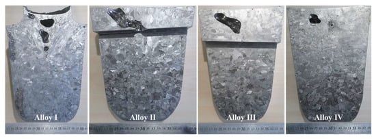
Figure 10.
Macrostructure of Ti-6Al-4V alloy ingots.
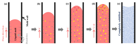
Figure 11.
The cessation mechanism of flow for Ti-6Al-4V ingot: (a–c) filling step in which the liquid metal is in motion; (d) stagnant step in which the velocity of liquid metal is zero; (e) completely solidified step.
4.2. Influence of Mold Design on Shrinkage Porosity
In this study, the influence of riser removal on mold filling and the solidification process of Ti-6Al-4V alloy mainly causes the following three effects. (1) The bottom-reaching time of the molten metal and the mold filling completion time are shortened (Figure 2e and Figure 4e). (2) The maximum flow velocity of the molten metal is decreased and the mold filling stability is improved (Figure 2f–j and Figure 5 a–e). (3) The shrinkage cavities move up along the central axis of the ingot and the cavity volume decreases significantly (Figure 3f and Figure 7a). On the one hand, the removal of the riser shortens the distance that the molten metal covers before reaching the bottom of the mold and reduces the total mass of the ingot, factors conducive to shortening the bottom-reaching time and the mold filling completion time. On the other hand, reducing the mold filling distance has the effect of decreasing the initial speed at which the molten metal reaches the bottom, slowing down the flow speed of the molten metal and improving the mold filling stability. Research shows that shortening the mold-filling time can effectively reduce heat loss in the mold-filling process and ensure good feeding during the solidification process [22,28]. These factors play an important role in reducing shrinkage cavity volume and changing the position of the shrinkage cavity. Based on this finding, Liu et al. [14] suggested that the filling time should be shortened as much as possible to ensure filling stability. In addition, after riser removal, the top area of the ingot can serve as a pool for feeding which is the fundamental reason why the shrinkage cavity moves up along the center line and its volume decreases. For mold I, the riser part solidifies earlier than any other part of the ingot in conformance with the layer-by-layer solidification pattern of titanium alloy ingots, cutting off the feeding channel earlier and promoting the formation of a shrinkage cavity. Huang et al. [29] explored the influence of the casting system on shrinkage porosity, and found that feeding becomes difficult when the sprue part solidifies earlier than the casting, resulting in a significantly increased probability of forming shrinkage cavities.
It can be seen from Figure 7 that when the top size of the ingot is reduced from 180 mm to 170 mm, while the volume of the shrinkage cavity is reduced from 0.061 cm3 to 0.059 cm3, the utilization rate of the ingot is reduced from 86.4% to 85.8%. When the bottom size of the ingot is reduced from 130 mm to 110 mm, the volume of the shrinkage cavity barely changes but the utilization rate of the ingot is increased to 86.7%. It is worth noting that changing the top or bottom size of the ingot means changing the mold taper. To further optimize the mold design, the influence of mold taper on the volume and distribution of shrinkage cavities was studied (Figure 12). It can be seen from Figure 12a,b that as the top size increases or the bottom size decreases (i.e., the mold taper increases), the shrinkage cavity volume decreases, and the ingot utilization rate increases, both significantly. Analysis reveals that increasing the top size is equivalent to increasing the volume of the pool for high-temperature molten metal, and decreasing the bottom size has the effect of increasing the solidification rate, both of which play an important role in promoting effective feeding, suppressing the formation of shrinkage cavities and making these move up along the central axis. Figure 12c,d show the quantitative relationship between mold taper and the shrinkage cavity, respectively. It is also found that the shrinkage cavity volume decreases significantly with increasing the mold taper, significantly increasing the ingot utilization rate.
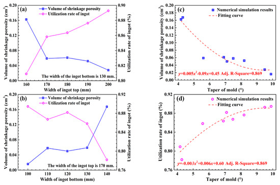
Figure 12.
Effect of top width (a), bottom width (b), and mold taper (c,d) for ingots on shrinkage porosity and utilization rate of ingots.
In summary, it is advisable to remove the riser in the design of casting molds of titanium alloy ingots of small mass. This not only ensures that shrinkage cavities are concentrated at the top part of the ingot, thereby improving the utilization rate of the ingot, but also reduces the production cost. However, the removal of the riser increases the design requirements of the mold in order to suppress the formation of shrinkage cavities and to move them to the top part of the ingot.
5. Conclusions
The effect of mold design on the shrinkage porosity of Ti-6Al-4V alloy ingots has been thoroughly investigated using numerical simulation and experimental verification. The main conclusions are the following.
- The presence of a riser in mold I results in a relatively high flow rate (2.394 m·s−1) of molten metal, significantly reducing the stability of the mold-filling process. In addition, the riser part solidifies earlier than the main body of the ingot in conformance with the layer-by-layer solidification pattern of titanium alloy. The riser, therefore, cannot serve the purpose of feeding effectively, resulting in a significantly larger shrinkage cavity volume (3.29 cm3) and a relatively low ingot utilization rate (63.6%).
- The removal of the riser shortens the bottom-reaching time of the molten metal and the mold-filling completion time. Therefore, the maximum flow velocity decreases (alloy II–IV: 2.228 m·s−1, 2.245 m·s−1, 2.198 m·s−1) and the filling stability increases, effectively suppressing the formation of shrinkage cavities (alloy II–IV: 0.061 cm3, 0.059 cm3, 0.058 cm3) and improving the ingot utilization rate significantly (alloy II–IV: 86.4%, 85.8%, 86.7%).
- The formation of shrinkage cavities in Ti-6Al-4V alloy ingots in this study is mainly due to the formation of an isolated liquid phase zone. This zone results from the formation of a grain frame caused by the intersection of a large number of equiaxed crystals. The inability of this last crystallization part to compensate for volume shrinkage ultimately leads to the formation of shrinkage cavities.
- With increasing top size or decreasing bottom size of the ingot (i.e., increasing mold taper), the volume of the shrinkage cavities decreases and the ingot utilization rate increases, both significantly. For instance, the shrinkage cavity volume of the ingot decreases from 0.162 cm3 to 0.016 cm3, and the utilization rate increases from 80.9% to 89.5% when the mold taper is increased from 4.2° to 9.9°. Analysis reveals that increasing the top size is equivalent to increasing the volume of the pool of high-temperature molten metal, and decreasing the bottom size has the effect of increasing the solidification rate, both of which play an important role in promoting effective feeding and suppressing the formation of shrinkage cavities.
Author Contributions
Conceptualization, T.H. and Y.C.; methodology, T.H.; software, T.H. and Y.C.; validation, T.H. and Y.C.; formal analysis, T.H.; investigation, T.H.; resources, Y.C.; data curation, T.H.; writing—original draft preparation, T.H.; writing—review and editing, T.H. and Y.C.; visualization, T.H.; supervision, Y.C.; project administration, Y.C.; funding acquisition, Y.C. All authors have read and agreed to the published version of the manuscript.
Funding
This work was financially supported by the Sichuan Science and Technology Program (No. 2019YFG0082).
Institutional Review Board Statement
Not applicable.
Informed Consent Statement
Not applicable.
Data Availability Statement
The data that support the findings of this study are available from the corresponding author, Yuyong Chen, upon reasonable request.
Conflicts of Interest
The authors declare that they have no conflict of interest.
References
- Williams, J.C.; Boyer, R.R. Opportunities and issues in the application of titanium alloys for aerospace components. Metals 2020, 10, 705. [Google Scholar] [CrossRef]
- Zhang, S.Y.; Li, J.S.; Kou, H.C.; Yang, J.R.; Yang, G.; Wang, J. Effects of thermal history on the microstructure evolution of Ti–6Al–4V during solidification. J. Mater. Process. Technol. 2016, 227, 281–287. [Google Scholar] [CrossRef]
- Feng, X.; Qiu, J.K.; Ma, Y.J.; Lei, J.F.; Cui, Y.Y.; Wu, X.H.; Yang, R. Influence of processing conditions on microstructure and mechanical properties of large thin-wall centrifugal Ti–6Al–4V casting. J. Mater. Sci. Technol. 2015, 32, 362–371. [Google Scholar] [CrossRef]
- Atkinson, H.V.; Davies, S. Fundamental aspects of hot isostatic pressing: An overview. Metall. Mater. Trans. A 2000, 31, 2981–3000. [Google Scholar] [CrossRef]
- Zhang, S.Y.; Li, J.S.; Kou, H.C.; Yang, J.R.; Yang, G.; Wang, J. Effect of mold temperature and casting dimension on microstructure and tensile properties of counter-gravity casting Ti–6Al–4V alloys. China Foundry 2016, 13, 9–14. [Google Scholar] [CrossRef]
- Yang, L.; Chai, L.H.; Liang, Y.F.; Zhang, Y.W.; Bao, C.L.; Liu, S.B.; Lin, J.P. Numerical simulation and experimental verification of gravity and centrifugal investment casting low pressure turbine blades for high Nb-TiAl alloy. Intermetallics 2015, 66, 149–155. [Google Scholar] [CrossRef]
- Suzuki, K.; Yao, M. Simulation of mold filling and solidification during centrifugal precision casting of Ti–6Al–4V alloy. Met. Mater. Int. 2004, 10, 33–38. [Google Scholar] [CrossRef]
- Jia, Y.; Xiao, S.L.; Tian, J.; Xu, L.J.; Chen, Y.Y. Modeling of TiAl alloy grating by investment casting. Metals 2015, 5, 2328–2339. [Google Scholar] [CrossRef]
- Zhang, S.Y.; Li, J.S.; Kou, H.C.; Yang, J.R.; Yang, G.; Wang, J. Numerical modeling and experiment of counter-gravity casting for titanium alloys. Int. J. Adv. Manuf. Technol. 2016, 85, 1877–1885. [Google Scholar] [CrossRef]
- Yang, J.R.; Wang, H.; Wu, Y.L.; Zhang, K.R.; Wang, X.Y.; Hu, R. Numerical calculation and experimental evaluation of counter-gravity investment casting of Ti–48Al–2Cr–2Nb alloy. Int. J. Adv. Manuf. Technol. 2018, 96, 3295–3309. [Google Scholar] [CrossRef]
- Xiong, C.; Ma, Y.C.; Chen, B.; Liu, K.; Li, Y.Y. Modeling of filling and solidification process for TiAl exhaust valves during suction casting. Acta. Metall. Sin. Engl. Lett. 2013, 26, 33–48. [Google Scholar] [CrossRef]
- Qi, Y.S.; Chen, L.L.; Chen, G.; Li, K.F.; Li, C.; Du, Z.M. Preparation and properties of special vehicle cover via a novel squeeze casting quantitative feeding system of molten metal. Metals 2020, 10, 266. [Google Scholar] [CrossRef]
- Dai, H.L.; Zhang, C.L.; Zhao, Q.; Zhu, H. The study of titanium alloy precision casting turbine blades based on Procast. IOP Conf. Ser. Mater. Sci. Eng. 2019, 677, 022090. [Google Scholar] [CrossRef]
- Liu, X.J.; Hao, Z.J.; Huang, M. Optimization of vacuum counter-pressure casting process for an aluminum alloy casing using numerical simulation and defect recognition techniques. Int. J. Adv. Manuf. Technol. 2020, 107, 2783–2795. [Google Scholar] [CrossRef]
- Shangguan, H.L.; Kang, J.W.; Yi, J.H.; Deng, C.Y.; Hu, Y.Y.; Huang, T. Controlled cooling of an aluminum alloy casting based on 3D printed rib reinforced shell mold. China Foundry 2018, 15, 210–215. [Google Scholar] [CrossRef]
- Zhao, J.; Zhang, Z.Y.; Liu, S.B.; Shi, K.; Bao, C.L.; Ning, Z.S.; Yan, P.; Wang, L.; Lou, Y.C. Elimination of misrun and gas hole defects of investment casting TiAl alloy turbocharger based on numerical simulation and experimental study. China Foundry 2020, 17, 29–34. [Google Scholar] [CrossRef]
- Eylon, D.; Keller, M.M.; Jones, P.E. Development of permanent-mold cast Ti–Al automotive valves. Intermetallics 1998, 6, 703–708. [Google Scholar] [CrossRef]
- Rishel, L.L.; Biery, N.E.; Raban, R.; Gandelsman, V.Z.; Pollock, T.M.; Cramb, A.W. Cast structure and property variability in gamma titanium aluminides. Intermetallics 1998, 6, 629–636. [Google Scholar] [CrossRef]
- Lasalmonie, A. Why is it so difficult to introduce them in gas turbine engines? Intermetallics 2006, 14, 1123–1129. [Google Scholar] [CrossRef]
- Gao, Y.; Zhang, L.J.; Gao, W.L.; Zhang, H. Prediction and improvement of shrinkage porosity in TiAl based alloy. China Foundry 2011, 8, 19–24. [Google Scholar]
- Mi, G.F.; Liu, X.Y.; Wang, K.F.; Fu, H.Z. Application of numerical simulation technique to casting process of valve block. J. Iron Steel Res. Int. 2009, 16, 12–17. [Google Scholar] [CrossRef]
- Liu, J.G.; Yang, L.; Fang, X.G.; Li, B.; Yang, Y.W.; Fang, L.Z.; Hu, Z.B. Numerical simulation and optimization of shell mould casting process for leaf spring bracket. China Foundry 2020, 17, 35–41. [Google Scholar] [CrossRef]
- Han, J.C.; Dong, J.; Zhang, S.Z.; Zhang, C.J.; Xiao, S.L.; Chen, Y.Y. Effect of TiB2 addition on microstructure and fluidity of cast TiAl alloy. Vacuum 2020, 174, 109210. [Google Scholar] [CrossRef]
- Yang, L.; Chai, L.H.; Zhang, L.Q.; Lin, J.P. Numerical simulation and process optimization of investment casting of the blades for high Nb containing TiAl alloy. Mater. Sci. Forum. 2013, 747, 105–110. [Google Scholar] [CrossRef]
- Zheng, H.S.; Zhang, Z.F.; Bai, Y.L. Numerical simulation and experimental study on compound casting of layered aluminum matrix composite brake drum. Materials 2021, 14, 1412. [Google Scholar] [CrossRef]
- Wang, J.H.; Guo, X.L.; Wang, L.Q.; Lu, W.J. The influence of B4C on the fluidity of Ti-6Al-4V-xB4C composites. Mater. Trans. 2014, 55, 1367–1371. [Google Scholar] [CrossRef]
- Dahle, A.K.; Karlsen, S.; Arnberg, L. Effect of grain refinement on the fluidity of some binary Al-Cu and Al-Mg alloys. Int. J. Cast Metal. Res. 1996, 9, 103–112. [Google Scholar] [CrossRef]
- Xuan, D.P.; Zhou, C.; Zhou, Y.; Jiang, T.L.; Zhu, B.J.; Fan, W.H.; Jia, Y.G. Numerical simulation of the top side-pouring twin-roll casting of 6.5wt.% Si steel process. Int. J. Adv. Manuf. Technol. 2022, 119, 2355–2368. [Google Scholar] [CrossRef]
- Huang, P.H.; Cheng, C.Y.; Huang, W.J.; Chou, C.S. Optimal design of investment casting system for toothed chain joint: Computer simulations and experimental verification. Int. J. Adv. Manuf. Technol. 2020, 106, 1931–1943. [Google Scholar] [CrossRef]
Publisher’s Note: MDPI stays neutral with regard to jurisdictional claims in published maps and institutional affiliations. |
© 2022 by the authors. Licensee MDPI, Basel, Switzerland. This article is an open access article distributed under the terms and conditions of the Creative Commons Attribution (CC BY) license (https://creativecommons.org/licenses/by/4.0/).