Article

Tailoring the Pore Structure of Porous Ni-Sn Alloys for Boosting Hydrogen Evolution Reaction in Alkali Solution

College of Mechanical Engineering, Wuhan Polytechnic University, Wuhan 430048, China
*
Author to whom correspondence should be addressed.
Metals 2022, 12(12), 2123; https://doi.org/10.3390/met12122123
Submission received: 11 November 2022 / Revised: 25 November 2022 / Accepted: 7 December 2022 / Published: 9 December 2022
(This article belongs to the Special Issue Plastic Forming, Microstructure, and Property Optimization of Metals)

Abstract

:
Ni-based alloy is an ideal candidate for its application in the field of hydrogen evolution of water splitting due to its good durability, excellent catalytic properties and low hydrogen evolution overpotential. In this paper, porous Ni-Sn alloy materials were prepared by activation reaction sintering, and the pore structure was tailored by adjusting Sn content. The effects of Sn content and electrolyte temperature on the hydrogen evolution properties of porous Ni-Sn alloy electrodes in 6 mol·L−1 KOH solution were studied by electrochemical measurement methods, such as cyclic voltammetry (CV) curves, electrochemical impedance spectroscopy (ESI) and linear sweep voltammetry, and the mechanism of hydrogen evolution was further discussed. The experimental results reveal that when Sn content is 45 wt%, porous Ni-Sn alloy exhibits the best catalytic performance for hydrogen evolution with a Tafel slope of 164.69 mV·dec−1 and an overpotential of 170 mV. The tested electrode also shows good stability for hydrogen evolution in alkaline solution, and the apparent activation energy calculated at room temperature is 29.645 kJ·mol−1. The catalytic mechanism of hydrogen evolution is as follows: the addition of Sn significantly reduces the dissociation degree of M-H bonds, thereby reducing the overpotential of hydrogen evolution; with the increase of Sn content, the porous Ni-Sn electrode displays a higher electrochemical active surface area (ECSA), which makes porous Ni-Sn alloy exhibit good hydrogen evolution catalytic performance.

1. Introduction

Development and use of renewable energy are now more crucial than ever due to the decline in non-renewable energy sources. Considering its advantages of being clean, pollution-free, and having high conversion efficiency, hydrogen energy has received a lot of attention [1,2]. According to recent research, there are numerous methods for producing hydrogen, including biological hydrogen production, hydrogen production from fossil fuels, hydrogen production from water splitting, and hydrogen production from solar energy. Compared with other hydrogen production methods, the advantage of electrolytic water hydrogen production is that the hydrogen produced is of high purity, environmentally friendly and renewable, and has a wide range of sources [3]. However, the development of a cathode material with high activity, high efficiency, and low hydrogen evolution overpotential is crucial to achieving industrialized hydrogen production from electrolytic water while lowering energy consumption. Pt, Pd, and other precious metals have been used in conventional hydrogen evolution cathodes [4,5]. The biggest issue with them, although they work well in the electrolytic water catalytic hydrogen evolution process, is their scarcity, high cost, and difficulty in achieving industrial production. Therefore, finding an ideal catalyst electrode with comparable hydrogen evolution performance and low cost is urgently needed.
Because the transition metal Ni is close to the equilibrium potential and the outermost layer has paired d electrons and half empty d orbitals, which can form M-H bonds with hydrogen atoms, nickel base alloy is one of the hydrogen evolution cathode materials with the most potential at the moment, claims the relevant report [6]. It is these properties that make nickel base alloy conducive to the transmission of electrons and the absorption and desorption of hydrogen during hydrogen evolution. Currently, nickel base alloys that can be used for catalytic hydrogen evolution are mainly binary nickel base alloys and ternary nickel base alloys. For binary nickel base alloys, Ni-Mo [7,8], Ni-Cu [9,10], Ni-Sn [11,12], Ni-Cr [13],Ni-Co [14] and Ni-Al [15] alloys have been commonly studied. For ternary nickel base alloys, Ni-Co-Sn [16,17] and Ni-Fe-Sn [18,19] alloys also have received much attention because they exhibit good electrochemical performance as electrode. Among the nickel base alloy mentioned above, the Ni-Sn alloy electrode stands out for its good durability, excellent catalysis, and low hydrogen evolution overpotential. In addition, nickel base alloys such as Ni-Al, Ni-Al-Mo, etc. [20], which are prepared by activation reaction sintering and used as electrode materials for electro catalytic hydrogen evolution, are sintered at temperatures above 900 °C. However, the sintering temperature of Ni-Sn alloy is only 650 °C, which can greatly reduce the energy consumption during preparation. In the work of Yamashita et al. [21], the influence of electrodeposition conditions (bath composition, temperature, current density, etc.) on HER overvoltage in alkaline solution was studied. The hydrogen evolution overvoltage is discovered to be practically independent of alloy composition in the range of 40 to 80 wt% of Ni by varying the deposition current density and concentration of SnCl2 in pyrophosphate glycine bath. Zhu et al. [12] prepared Ni-Sn alloy by potentiostatic electrodeposition technique and studied its electrocatalytic properties. The results indicated that Ni-Sn alloy exhibits high durability in 30 wt% KOH solution. The Ni-Sn alloy deposited potentiostatically possess high activity and long-term stability as HER catalysts under alkaline condition, which suggests that it can be applied as the cathode in industrial water electrolyzer.
However, the element composition ratio and the thickness of the deposition layer cannot be properly controlled by the electrodeposition process. Based on the aforementioned issues, this paper uses Ni element and low melting point Sn element powder as raw materials to prepare porous Ni-Sn alloy by activation reaction sintering, which can precisely control the element composition ratio while realizing the near net forming of products, and studies its hydrogen evolution catalytic performance, laying the groundwork for its application in the field of hydrogen production from electrolytic water.

2. Materials and Methods

2.1. Preparation of Porous Ni-Sn Alloy

Ni powder and Sn powder with uniform particle size and a purity higher than 99.5 wt% were selected as the original powder. The mass ratio of mixed powders was Ni-x wt% Sn (x = 5~50, with an increment of 5). According to the literature [22], the raw materials of different mass ratio were blended in a stirrer at a stirring rate of 200 r·min−1 with a ball-to powder weight ratio of 5:1 for 5 h. Under the pressure of 160 MPa, the mixed powders were pressed to compacts with a dimension of Φ 25 mm × 2 mm. The as-pressed compacts were then heated in a vacuum furnace with a vacuum of 2.0 × 10⁻³ Pa and a heating rate of 278 K·min−1. Three heating holding platforms were necessary during sintering, which were 393 K for 30 min, 473 K for 240 min and 923 K for 60 min.

2.2. Instruments and Reagents for Experiments

Ni powder (−200~+400 mesh), Sn powder (−200~+400 mesh), absolute ethanol (analytical pure, Sinopharm Chemical Reagent Co., Ltd. Shanghai, China). Vacuum sintering furnace (Hunan Xubo Metallurgical Technology Co., Ltd. Changsha, China, XBZK-150); Omni directional planetary ball mill (Nanjing Nanda Instrument Co., Ltd. Nanjing, China, QM-QX2); JSM-6700 field emission scanning electron microscope (working voltage 5.0 kV) of JEOL Company of Japan; CHI660E electrochemical workstation of Shanghai Chenhua Instrument Co., Ltd. Shanghai, China.

2.3. Experiment in Electrochemical Testing

Electrochemical workstations were used to test the performance of hydrogen evolution, and the test system was a typical three electrode system. The porous Ni-Sn alloy after sintering was encapsulated by resin, and the single surface area of 1 cm2 was exposed, which was the working electrode. The platinum electrode was the counter electrode (CE), Hg/HgO electrode was the reference electrode (RE). Commonly, potassium will affect the stability of water [23,24]. However, studies show that the conventional electrolytic water solutions are NaOH and KOH. Compared with these two, KOH solution has higher electrolysis efficiency and requires less electrolysis voltage. Therefore, KOH solution is selected. In addition, increasing the electrolyte concentration is conducive to hydrogen evolution. However, if the electrolyte concentration is too high, the viscosity of solution will increase, and the diffusion and migration of ions will be greatly limited. Therefore, 6 M KOH solution is selected. Impurities were first eliminated using a current of −0.8 A. After that, the cyclic voltammetry (CV) curves were captured at the scan rates of 1, 2, 5, 10, 20, and 30 mV·s−1. Under various voltages, electrochemical impedance spectroscopy (EIS) curves of the porous Ni-45 wt% Sn binary alloy electrode were recorded. At scan rates of 5 mV·s−1, the linear polarization curves of Ni-45 wt% Sn electrode were captured at 303 K, 313 K, 323 K, 333 K and 343 K by linear sweep voltammetry (LSV).

3. Results and Discussion

3.1. Characterization of Ni-Sn Electrode

Parameters of pore structure like open porosity and overall porosity are illustrated in Figure 1a. First, the overall porosity and open porosity decrease slightly with the increasing amount of Sn for the capillary action of molten Sn. After that, with the continuous increase of Sn content, the diffusion rate of Sn element is higher than that of Ni element [22]. The rapid diffusion of Sn element will produce Kirkendall pores in the original position of Sn particles, and the further growth of pores will lead to the overall connectivity of pores in the green compact, which results in the increase of porosity. Figure 1b is a scanning electron microscope photo of the samples sintered at 650 °C. According to Figure 1b, the sample features a smooth material surface, a sintering neck at the intersection of the pores, and a rich pore structure and uniform distribution. In order to verify the existence of segregation phenomenon, EDS was tested on Ni-50 wt% Sn alloy. Figure 1c is the original SEM image of porous Ni-Sn alloy, and Figure 1d,e are the distribution map of Ni element and Sn element, respectively. Since the distribution of Ni and Sn elements is uniform, it can be concluded that the sample has no surface segregation phenomenon.

3.2. Electrochemical Characterization of Ni-Sn Electrode

Figure 2a shows the cyclic voltammogram of porous Ni-15 wt% Sn electrode obtained at different scan rates in the range of −0.52 V~−0.42 V vs. RHE, the calculation formula of standard hydrogen electrode potential is shown in literature [6], which is used to measure the capacitance of its electric double layer. The variation of the average of double layer current densities jd1,ave = (|jc| + |ja|)/2 as a function of potential sweep rate is described as follows:
j d 1 , a v e = C d 1 ( d E / d t )
where Cd1 is the double layer capacitance of the electrode, and jc and ja are cathodic and anodic current density, respectively. In order to get the real surface area, the double layer capacitance is usually used to calculate the roughness to get a relative standard value. During linear scanning, the current on the electrode consists of two parts:
i = i c + i f
where ic is the charging and discharging current, if is the faraday current. However,
i c = C d l d φ d t + φ d C d l d t
where the scan rate is fixed and Cdl is almost unchanged when the scanning range is small, thus
i c = C d l d φ d t = c o n s t
The relationship between double layer current and scan rate can be plotted as a straight line, where the slope is the Cdl. So, the ECSA of the electrode can be expressed as
ECSA = C d l 20   μ F · cm 2
where 20 μF·cm−2 represents the double layer capacitance of the smooth Hg electrode, which is used as the reference of roughness [25]. Scan rates are the abscissa and the points where the median line of the open circuit potential intersecting with CV curves are the ordinate. The relationship is shown in Figure 2b, where the exchange current density is proportional to the scan rate. Generally, ECSA can be used to measure the catalytic activity of electrodes. It can be calculated from Figure 2b that the ECSA of Ni-15 wt% Sn electrode is 345.5 cm2.
Figure 3 depicts the relationship between the electrochemical active surface area determined by the method above and Sn content. The figure demonstrates that the ECSA of the electrode exhibits a trend of first dropping and then increasing with the increase in Sn content. The minimum value is 175.5 when the mass percentage of tin is 25 wt%, suggesting that the sample’s ECSA is at its lowest. Related literature [26] shows that the ECSA of pure porous Ni electrode in 6 mol·L−1 KOH solution is 30.49 cm2, so the ECSA of porous Ni-Sn alloy under the same conditions is larger than that of pure Ni. Combined with Figure 1a and Figure 3, the ECSA of the Ni-Sn electrode can be determined to be nearly equivalent to the curve trend of its porosity with Sn content. Both of them show a trend of first decreasing and then increasing, and when the content of Sn is 45 wt%, ECSA reaches the maximum value of 494.7 cm2.

3.3. The Influence of Tested Parameters on HER Performance

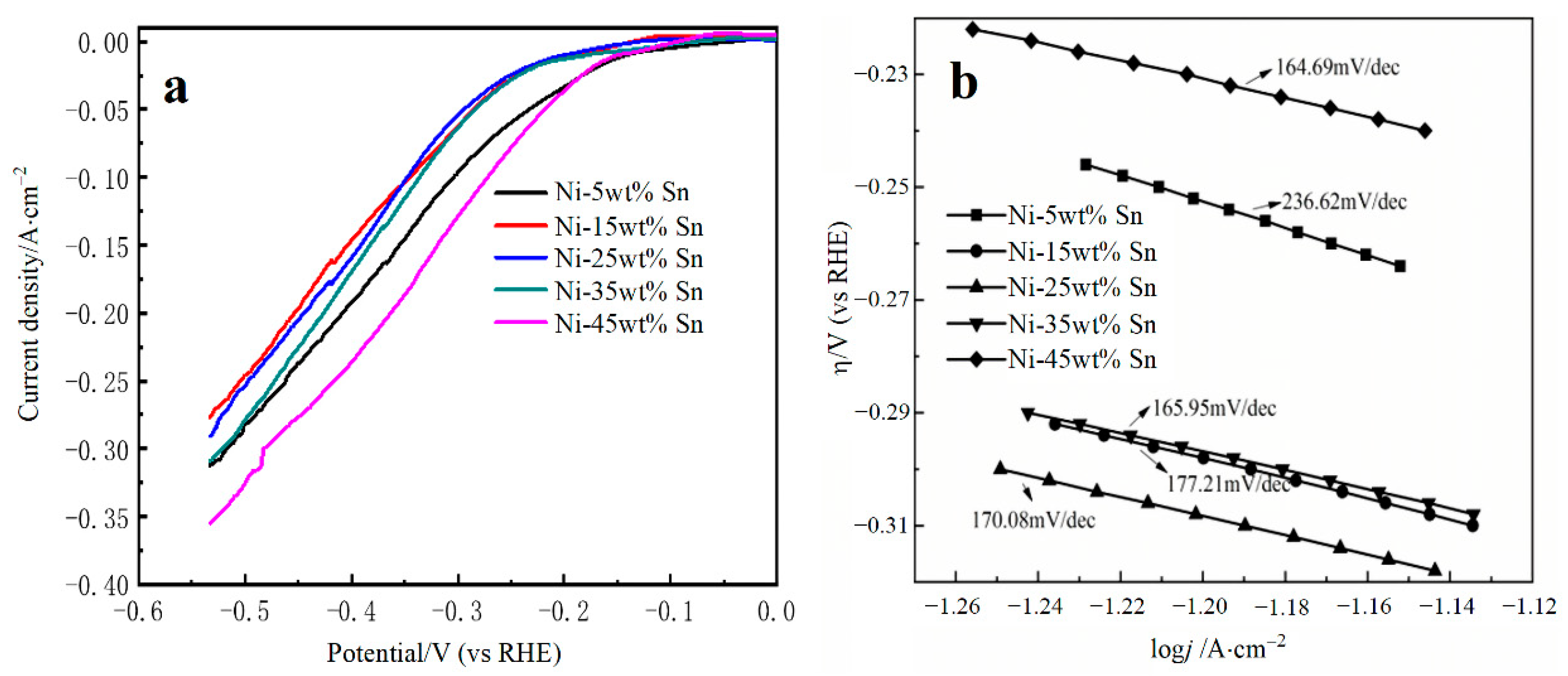
In order to investigate the influence of Sn content on the catalytic performance of porous Ni-Sn alloy electrode for hydrogen evolution, this study tested the cathodic polarization curve of porous Ni-Sn alloy. The experiment results, as shown in Figure 4a, were obtained at a scan rate of 5 mV·s−1 in 6 mol·L−1 KOH solution for electrode materials with Sn content of 5 wt%, 15 wt%, 25 wt%, 35 wt% and 45 wt%, respectively. The catalytic parameters for hydrogen evolution are shown in Table 1. Figure 4b shows that the Tafel slope of porous Ni-Sn alloy steadily decreases as Sn content rises, indicating that the catalytic activity for hydrogen evolution is gradually rising. It is worth noting that at a fixed overvoltage value of −0.33 V, the porous alloy with 45 wt% Sn content has the highest hydrogen evolution exchange current density of 0.166 A·cm−2, its Tafel slope is 164.69 mV·dec−1, and the hydrogen evolution overpotential is 170 mV, indicating that the electrode displays the best hydrogen evolution catalytic performance.
The Tafel slope, which is typically used to assess the effectiveness of the hydrogen evolution reaction, is defined by the step with the slowest reaction rate in accordance with the pertinent literature [27]. The Volmer reaction determined hydrogen evolution reaction process results in a Tafel slope that is higher than 116 mV·dec−1. The Tafel slope for the electrochemical desorption reaction determined hydrogen evolution reaction is 38 mV·dec−1. While the Tafel slope is the most optimum value, 29 mV·dec−1, for the hydrogen evolution reaction as determined by composite desorption reaction. Therefore, it can be concluded that the reaction control step of porous Ni-Sn alloy in alkaline solution is the Volmer reaction step.
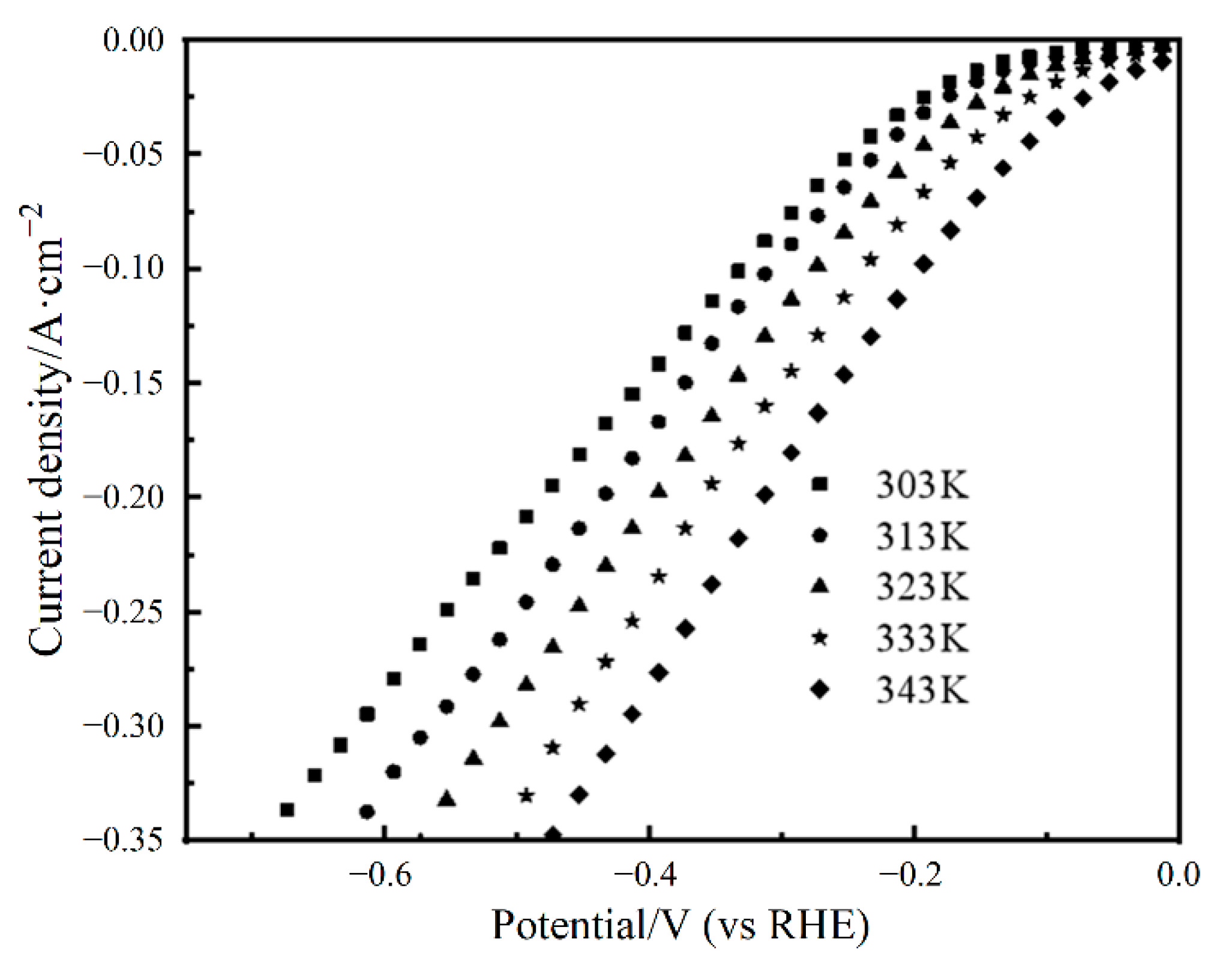
The polarization curve of porous Ni-45 wt% Sn alloy at various temperatures is shown in Figure 5. The testing ranges from 303 K to 343 K. As seen in the figure, the electrolyte temperature has a significant impact on the ability of porous Ni-Sn to catalyze reactions. The hydrogen evolution activity of porous alloy is improved as a result of the significant rise in exchange current density and decrease in hydrogen evolution overpotential with the increment of temperature. Therefore, it can be concluded that the porous Ni-Sn has excellent catalytic performance in the temperature range of 303–343 K, and it also shows that the designed electrode has a wide temperature range and good temperature stability. Additionally, it was discovered that the exchange current density changed significantly at a lower electrolyte temperature, although the cathodic polarization curve displayed a similar Tafel slope as the temperature rose. The exchange current density and hydrogen evolution overpotential reduced when the temperature rose to a specific level, showing that the catalytic activity of porous Ni-Sn alloy for hydrogen evolution diminished. The cause for this phenomenon is that when the electrolyte temperature is in a certain range, increasing the temperature properly can reduce the viscosity of the solution, which is beneficial to the thermal movement of the ions and accelerates the mass transfer process, thereby reducing the hydrogen evolution overpotential.
The apparent activation energy can truly reflect the catalytic performance of the catalyst to a certain extent, that is, the materials with higher apparent activation energy are more likely to catalyze hydrogen evolution and can also reflect the influence of temperature, an important factor, on the catalytic hydrogen evolution reaction. The apparent activation energy, current density, and temperature have the following relationships according to the Arrhenius equation [28]:
log j 0 = log A E a 2.303 R T
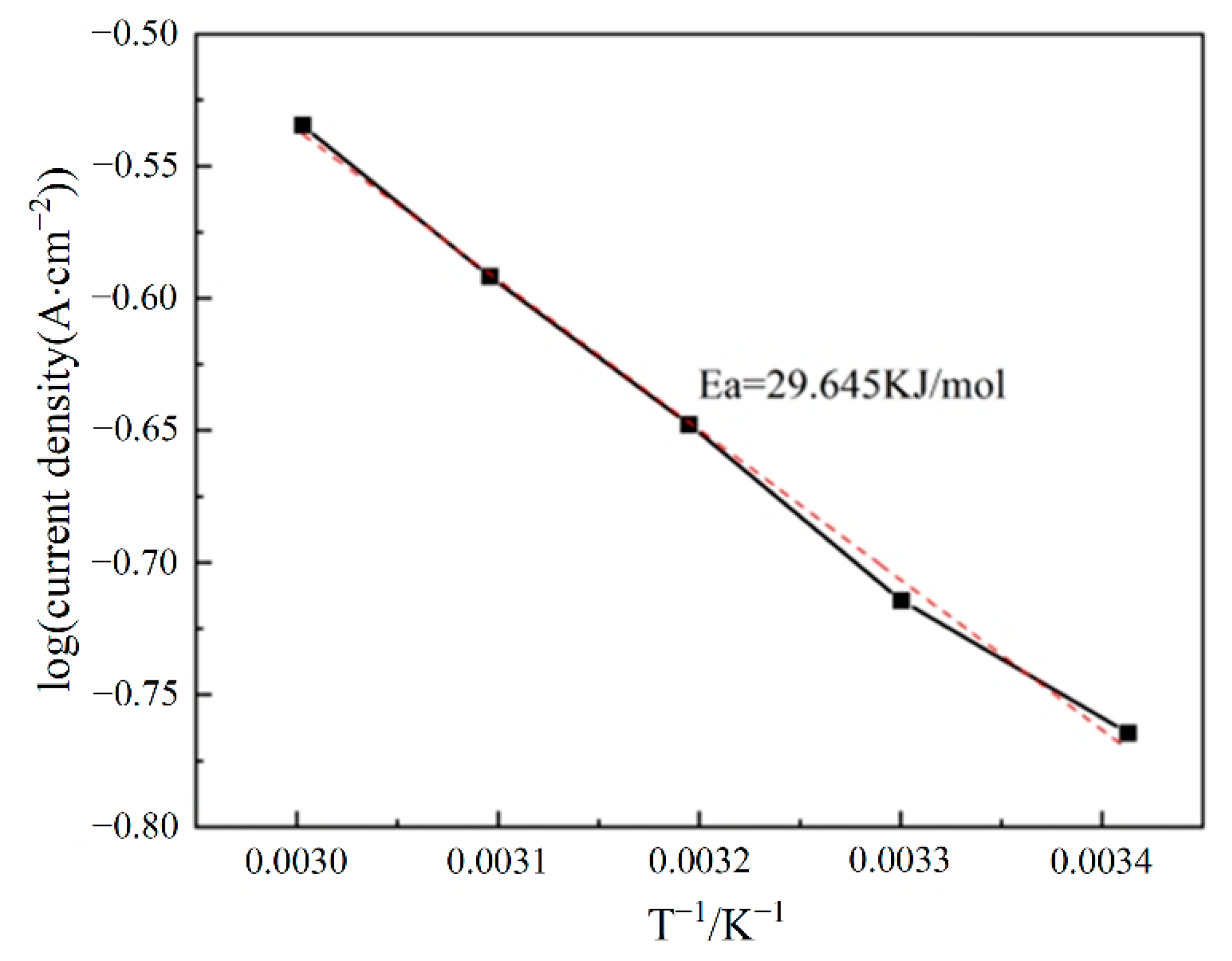
where A is a numeric constant, Ea the apparent activation energy for HER, R the gas constant. The apparent activation energy can be calculated by the slope. The points corresponding to logj0 and T−1 are shown in Figure 6. From the slope of the figure, the apparent activation energy of porous Ni-Sn alloy in 6 mol·L−1 KOH solution is 29.645 kJ·mol−1. Compared with the apparent activation energy of some commonly used hydrogen evolution cathode materials, the activation energy of Ni is 35 kJ·mol−1, and the activation energy of Fe is 39 kJ·mol−1 [29]. The apparent activation energy of porous Ni-Sn alloy is significantly lower than that of the above two materials, which indicates that porous Ni-Sn electrode is more prone to hydrogen evolution reaction than pure Ni electrode, and it also shows that it has higher hydrogen evolution catalytic activity.
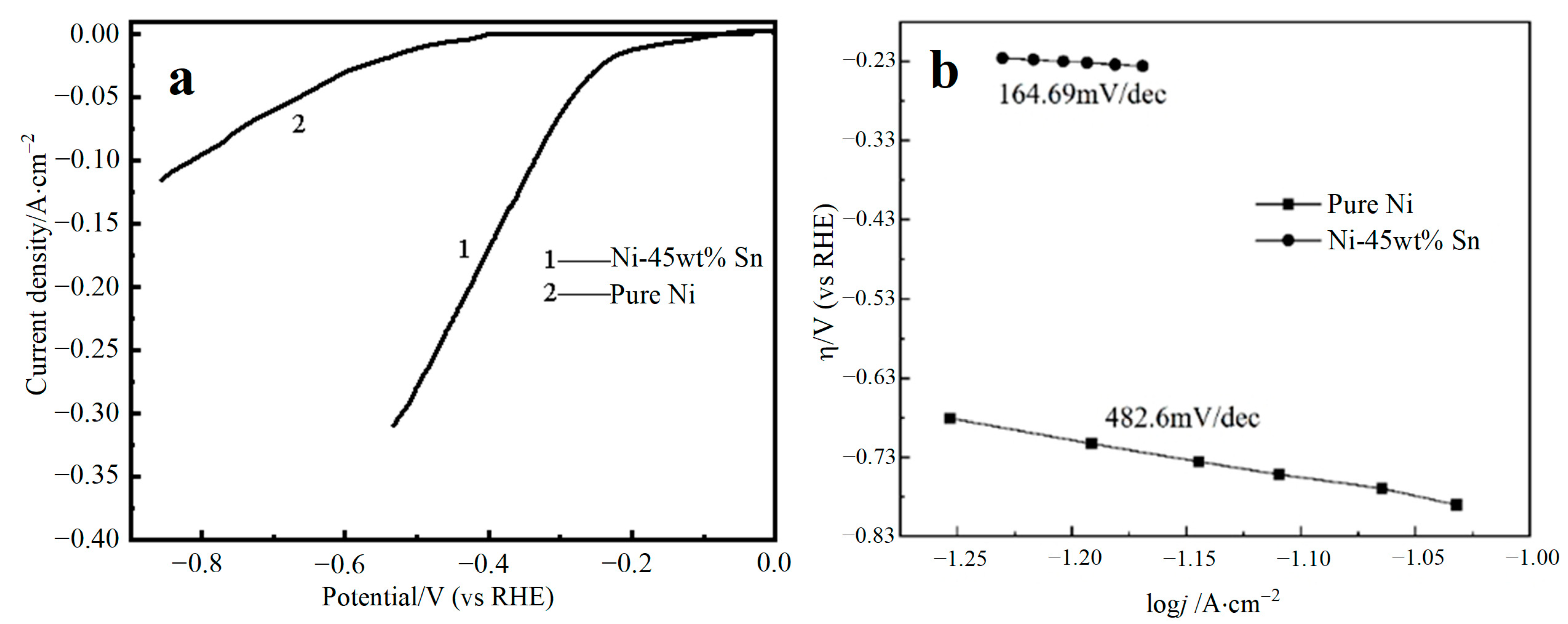
In order to compare the catalytic activity of Ni-Sn porous material and pure Ni (porous nickel), the linear polarization curves of Ni-Sn porous material and pure Ni (porous nickel) in 6 mol·L−1 KOH solution are presented in Figure 7 and the associated catalytic parameters are reported in Table 2. Through comparison, it can be seen that porous Ni-45 wt% Sn has a lower hydrogen evolution overpotential. When the current density is fixed at 20 mA·cm−2, the hydrogen evolution overpotential of porous Ni-45 wt% Sn alloy is 338 mV lower than that of porous nickel, indicating that it is more prone for Ni-45 wt% Sn binary alloy electrode to hydrogen evolution reaction. The cathodic hydrogen evolution current density reflects the speed of hydrogen evolution reaction. The higher the hydrogen evolution current density, the higher the hydrogen evolution reaction rate. Additionally, it shows that the catalytic activity of Ni-Sn binary alloy electrode for hydrogen evolution is significantly enhanced by the addition of the Sn element.
The kinetic parameters of hydrogen evolution in this experiment can be calculated by Tafel formula. The relationship between the two is as follows:
η = a   +   b log j
where η is the actual overpotential, j is the exchange current density, a is the intercept and b is the Tafel slope.
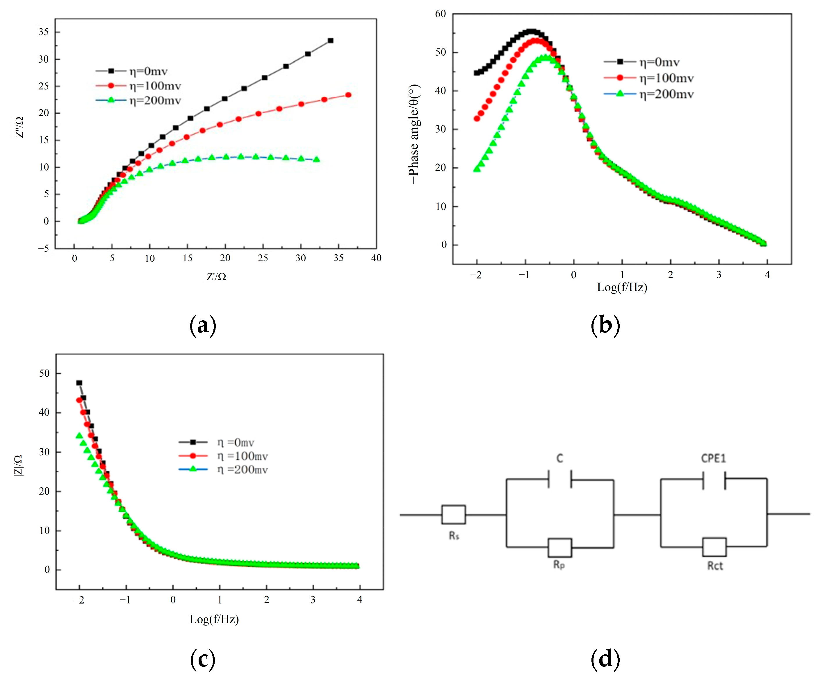
It is clear from the previously obtained linear polarization curve that Ni-45 wt% Sn exhibits the optimum hydrogen evolution capability. Electrochemical impedance spectroscopy (EIS) was performed on Ni-45 wt% Sn to study the interface conditions and electrocatalytic activity during the hydrogen evolution reaction. The cathodic overpotentials varied from 0 to 200 mV were increased every 100 mV. The Nyquist and Bode plots are shown in Figure 8, where the scan frequency range for the test impedance is 105–10−2 Hz, and the scan rate is 10 mV·s−1. It can be seen from the Nyquist diagram (Figure 8a) that two semicircles exist in the high frequency region and low frequency region respectively, which indicates that there are two time constants. However, these two semicircular curves deviate from the normal trajectory, which is called capacitive reactance arc, and this phenomenon is generally called “dispersion effect”. The conductivity of the solution, the adsorption layer on the electrode surface, and the homogeneity of the electrode surface all play a role in this effect [30]. In the process of hydrogen evolution catalytic reaction, the high frequency (HF) semicircle is related to the pore structure of the hydrogen evolution material, and it can be found that its radius does not change with the increase of overpotential, while the low frequency (LF) semicircle is generally related to the kinetics of hydrogen evolution, which is the result of electrochemical reaction, showing that its radius gradually decreases with the increase of overpotential. Figure 8d depicts the equivalent circuit of porous Ni-Sn alloy in the catalytic hydrogen evolution reaction, where Rs is solution resistance, C is double layer capacitance, CPE is constant phase element, Rp is mass transfer resistance, Rct is charge transfer resistance, and the semicircle of the high frequency section is expressed as Rp-C in series. Table 3 displays the data from the Zview software fitting. It can be found that the values of solution resistance Rs and mass transfer resistance Rp do not change significantly with the increase of the overvoltage, while the value of Rct decreases gradually with the increase of the overvoltage, which is consistent with the changing trend of the LF semicircle mentioned above. This demonstrates that as the overpotential increases, the resistance to the charge transfer process decreases and the catalytic reaction for hydrogen evolution becomes easier to perform.

3.4. Electrocatalytic Stability of Electrode Materials

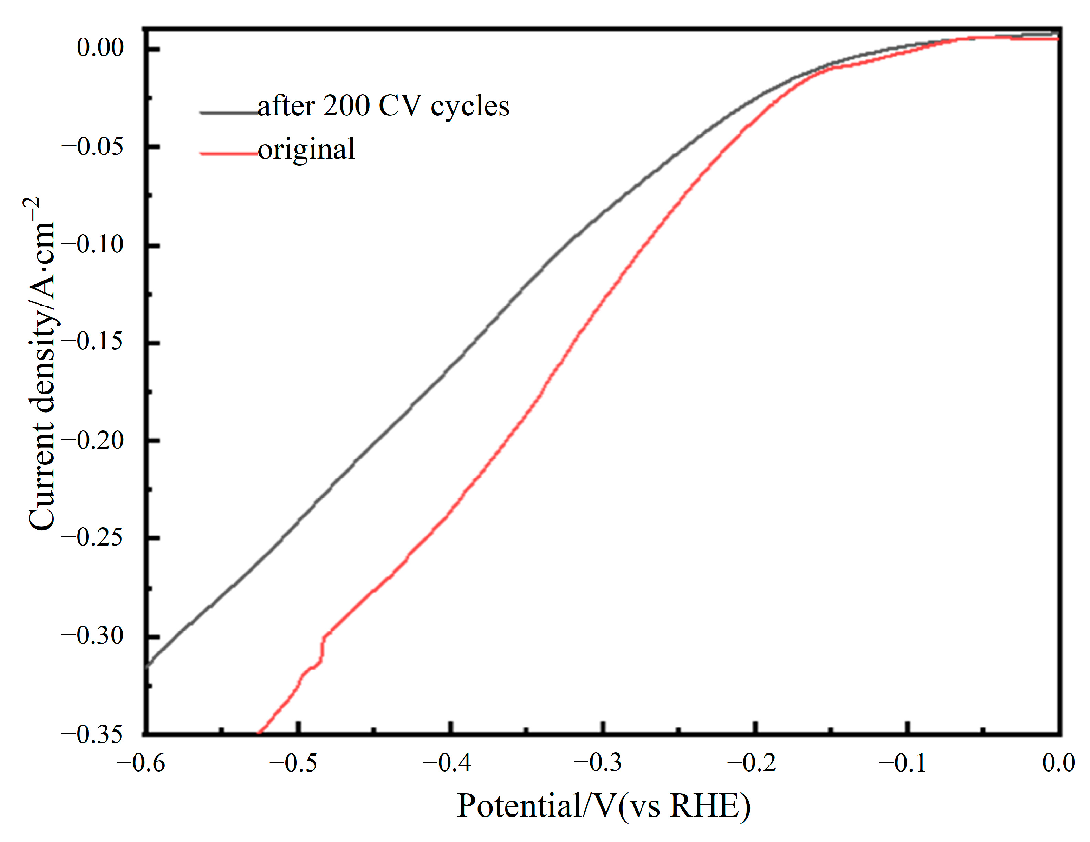
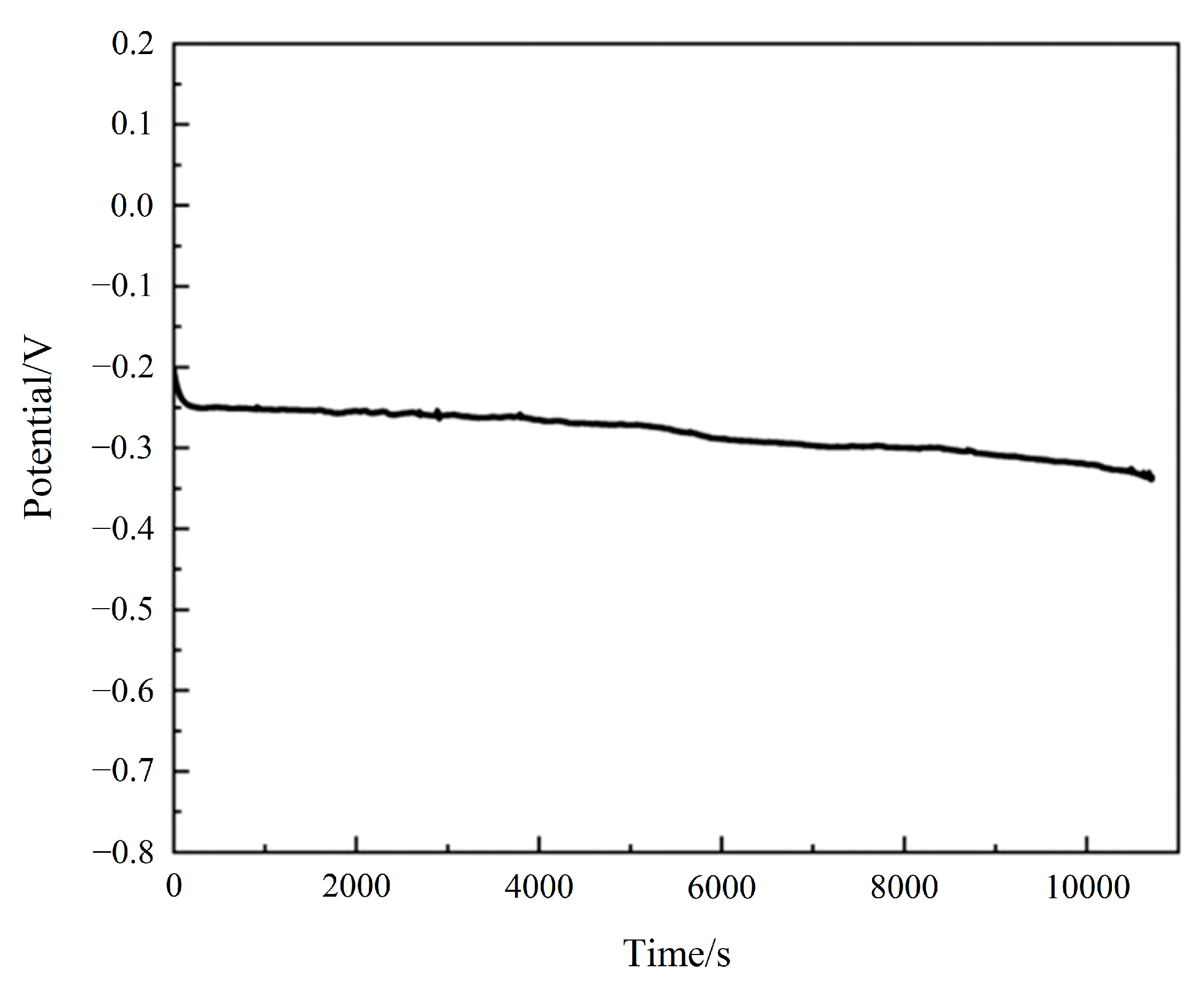
It is important to consider the stability of electrode materials with excellent catalytic performance for hydrogen evolution in addition to their high catalytic activity. In order to test the cycle stability, this experiment performs 200 CV cycles at a scanning speed of 100 mV·s−1. The LSV is then tested and recorded before and after the 200 CV cycles, resulting in the curve depicted in Figure 9. Findings show that there is little difference between the LSV curve before and after 200 cycles of CV testing, demonstrating a good catalytic stability for hydrogen evolution. Additionally, the curve depicted in Figure 10 is obtained by using the open circuit potential-time to assess its stability. The open circuit potential position is stable at −0.339 V after the open circuit potential test lasting up to 3 h, as shown in the figure, and the open circuit potential changed little throughout the entire test process, further demonstrating its high chemical stability.

3.5. Reaction Mechanism of HER

The electrolytic catalytic HER in alkaline solution generally consists of three steps [31]:
(1) Electrochemical discharge reaction. (Volmer step)
M + H 2 O + e M H + OH
(2) Electrochemical desorption reaction. (Heyrovsky step)
M H + H 2 O + e H 2 + M + OH
(3) Composite desorption reaction. (Tafel step)
M H + M H 2 M + H 2
The following two criteria are used to assess the catalytic performance of cathode in hydrogen evolution: hydrogen desorption rate and hydrogen adsorption rate. The ability to absorb and desorb hydrogen is generally required for the ideal hydrogen evolution cathode material to satisfy both of the aforementioned requirements simultaneously. The mechanism of hydrogen evolution reaction is the M-H bond on the surface of the electrode formed by the electrochemical reaction, and then broken in some way to release the adsorbed hydrogen (composite desorption or electrochemical desorption). The adsorption free energy determines whether an M-H bond forms. The step of electrochemical reaction can be accelerated by appropriately raising the adsorption free energy. However, the adsorbed hydrogen atoms will find it challenging to separate from the M-H bond due to excessive adsorption free energy, which will slow down the reaction.
Ni is a metal with a medium overpotential. The adsorption of the H atom is strong on Ni and the reduction of H+ is simple, so the precipitation of H2 is hindered. Due to the hydrogen’s ease of desorption on the Ni-Sn alloy electrode, the Ni-Sn alloy formed after the addition of Sn exhibits low hydrogen evolution overpotential. According to Table 1, when the content of Sn is high, the Ni-Sn electrode material has a high electrode electrochemical active surface area, which is one of the reasons for its better performance.

4. Conclusions

This study examined the catalytic properties of porous Ni-Sn alloy that were synthesized by sintering Ni and Sn elemental powders using the activation reaction method. The catalytic properties for hydrogen evolution in 6 mol·L−1 KOH solution were studied, and the mechanism of hydrogen evolution was discussed. The results are as follows:
(1) Ni and Sn porous materials have excellent catalytic performance for hydrogen evolution, and the sample with Ni-45 wt% Sn (maximum porosity) has the best hydrogen evolution performance. The Tafel slope is 164.69 mV·dec−1 and the hydrogen evolution overpotential is 170 mV. Additionally, the control step is the Volmer reaction step. The apparent activation energy of hydrogen evolution at room temperature is 29.645 kJ·mol−1, which is lower than that of Ni (35 kJ·mol−1);
(2) After a 3 h open circuit potential-time test and 200 CV cycles, the catalytic stability of porous Ni-Sn alloy for hydrogen evolution is good, and the fluctuation is small;
(3) The hydrogen evolution catalytic mechanism of porous Ni-Sn alloy is as follows: because the adsorbed hydrogen on the Ni-Sn alloy electrode is easily desorbed, the degree of dissociation of the M-H bond is greatly lowered, and the hydrogen evolution overpotential is reduced. Furthermore, when the Sn concentration is high, the Ni-Sn electrode material has a high electrochemical active surface area, resulting in good hydrogen evolution catalytic performance for the porous Ni-Sn electrode, which is one of the reasons for its better performance.

Author Contributions

Conceptualization, J.Y.; funding acquisition, J.Y.; methodology, J.L.; investigation, J.L., W.L. and S.T.; software, Y.F.; resources, Y.F. and J.L.; validation, Y.W., S.D. and J.Y.; formal analysis, Y.K.; data curation, G.X. and B.W.; writing—original draft preparation, J.L.; writing—review and editing, J.L. and J.Y.; visualization, Z.Y.; supervision, J.Y. All authors have read and agreed to the published version of the manuscript.

Funding

This research was funded by the Natural Science Foundation of China, grant number 51704221.

Conflicts of Interest

The authors declare no conflict of interest.

References

  1. Acar, C.; Dincer, I. The potential role of hydrogen as a sustainable transportation fuel to combat global warming. Int. J. Hydrog. Energy 2020, 45, 3396–3406. [Google Scholar] [CrossRef]
  2. Dawood, F.; Anda, M.; Shafiullah, G.M. Hydrogen production for energy: An overview. Int. J. Hydrog. Energy 2020, 45, 3847–3869. [Google Scholar] [CrossRef]
  3. Anwar, S.; Khan, F.; Zhang, Y.; Djire, A. Recent development in electrocatalysts for hydrogen production through water electrolysis. Int. J. Hydrog. Energy 2021, 46, 32284–32317. [Google Scholar] [CrossRef]
  4. Chinchilla, R.; Najera, C. Chemicals from alkynes with palladium catalysts. Chem. Rev. 2014, 114, 1783–1826. [Google Scholar] [CrossRef] [Green Version]
  5. Zhu, J.; Hu, L.; Zhao, P.; Lee, L.Y.S.; Wong, K.Y. Recent Advances in Electrocatalytic Hydrogen Evolution Using Nanoparticles. Chem. Rev. 2020, 120, 851–918. [Google Scholar] [CrossRef]
  6. Li, X.; Yang, J.; Feng, X.; Hu, Y.; Zou, H.; Zhang, C.; Xiong, L.; Zheng, X.; Liu, Y. Electrochemical performance of porous Ni–Cr–Mo–Cu alloys for hydrogen evolution reactions in alkali solution. Mater. Res. Express 2020, 7, 095505. [Google Scholar] [CrossRef]
  7. Wijten, J.H.J.; Riemersma, R.L.; Gauthier, J.; Mandemaker, L.D.B.; Verhoeven, M.; Hofmann, J.P.; Chan, K.; Weckhuysen, B.M. Electrolyte Effects on the Stability of Ni-Mo Cathodes for the Hydrogen Evolution Reaction. ChemSusChem 2019, 12, 3491–3500. [Google Scholar] [CrossRef] [Green Version]
  8. Bau, J.A.; Kozlov, S.M.; Azofra, L.M.; Ould-Chikh, S.; Emwas, A.-H.; Idriss, H.; Cavallo, L.; Takanabe, K. Role of Oxidized Mo Species on the Active Surface of Ni–Mo Electrocatalysts for Hydrogen Evolution under Alkaline Conditions. ACS Catal. 2020, 10, 12858–12866. [Google Scholar] [CrossRef]
  9. Gao, M.Y.; Yang, C.; Zhang, Q.B.; Yu, Y.W.; Hua, Y.X.; Li, Y.; Dong, P. Electrochemical fabrication of porous Ni-Cu alloy nanosheets with high catalytic activity for hydrogen evolution. Electrochim. Acta 2016, 215, 609–616. [Google Scholar] [CrossRef]
  10. Cardoso, D.S.P.; Eugénio, S.; Silva, T.M.; Santos, D.M.F.; Sequeira, C.A.C.; Montemor, M.F. Hydrogen evolution on nanostructured Ni–Cu foams. RSC Adv. 2015, 5, 43456–43461. [Google Scholar] [CrossRef]
  11. Jović, V.D.; Lačnjevac, U.; Jović, B.M.; Karanović, L.; Krstajić, N.V. Ni–Sn coatings as cathodes for hydrogen evolution in alkaline solution. Chemical composition, phase composition and morphology effects. Int. J. Hydrog. Energy 2012, 37, 17882–17891. [Google Scholar] [CrossRef]
  12. Zhu, Y.; Zhang, X.; Song, J.; Wang, W.; Yue, F.; Ma, Q. Microstructure and hydrogen evolution catalytic properties of Ni-Sn alloys prepared by electrodeposition method. Appl. Catal. A Gen. 2015, 500, 51–57. [Google Scholar] [CrossRef]
  13. Qazi, U.Y.; Javaid, R.; Tahir, N.; Jamil, A.; Afzal, A. Design of advanced self-supported electrode by surface modification of copper foam with transition metals for efficient hydrogen evolution reaction. Int. J. Hydrog. Energy 2020, 45, 33396–33406. [Google Scholar] [CrossRef]
  14. Qazi, U.Y.; Javaid, R.; Zahid, M.; Tahir, N.; Afzal, A.; Lin, X.-M. Bimetallic NiCo–NiCoO2 nano-heterostructures embedded on copper foam as a self-supported bifunctional electrode for water oxidation and hydrogen production in alkaline media. Int. J. Hydrog. Energy 2021, 46, 18936–18948. [Google Scholar] [CrossRef]
  15. Los, P.; Rami, A.; Lasia, A. Hydrogen evolution reaction on Ni-Al electrodes. J. Appl. Electrochem. 1993, 23, 135–140. [Google Scholar] [CrossRef]
  16. Liu, Y.; Lu, H.; Kou, X. Electrodeposited Ni-Co-Sn alloy as a highly efficient electrocatalyst for water splitting. Int. J. Hydrog. Energy 2019, 44, 8099–8108. [Google Scholar] [CrossRef]
  17. Vijayakumar, J.; Mohan, S.; Anand Kumar, S.; Suseendiran, S.R.; Pavithra, S. Electrodeposition of Ni–Co–Sn alloy from choline chloride-based deep eutectic solvent and characterization as cathode for hydrogen evolution in alkaline solution. Int. J. Hydrog. Energy 2013, 38, 10208–10214. [Google Scholar] [CrossRef]
  18. Wu, Y.; Zhang, Y.; Wang, Y.; He, Z.; Gu, Z.; You, S. Potentiostatic electrodeposited of Ni–Fe–Sn on Ni foam served as an excellent electrocatalyst for hydrogen evolution reaction. Int. J. Hydrog. Energy 2021, 46, 26930–26939. [Google Scholar] [CrossRef]
  19. Zhang, H.; Li, F.; Ji, S.; Yang, J.; Zhang, C.; Yang, F.; Lei, L. One-step electrodeposition of cauliflower-like Ni–Fe–Sn particles as a highly-efficient electrocatalyst for the hydrogen evolution reaction. Int. J. Hydrog. Energy 2020, 45, 24615–24625. [Google Scholar] [CrossRef]
  20. Wu, L. Fabrication and Properties of Ni-Based Porous Alloys; Central South University: Changsha, China, 2013. [Google Scholar]
  21. Yamashita, H.; Yamamura, T.; Yoshimoto, K. The Relation Between Catalytic Ability for Hydrogen Evolution Reaction and Characteristics of Nickel-Tin Alloys. J. Electrochem. Soc. 2019, 140, 2238–2243. [Google Scholar] [CrossRef]
  22. Li, X.D.; Fan, Y.Q.; Liu, Y.Z.; Liu, J.L.; Yang, J.S.; Zhu, Y.; Li, J.; Liu, B. Effect of Sn Content on the Pore Structures of Porous Ni-Sn Alloys Produced by Reactive Synthesis Sintering Method. J. Mater. Eng. Perform. 2022. [Google Scholar] [CrossRef]
  23. Blass, P.M.; Zhou, X.L.; White, J.M. Coadsorption and reaction of water and potassium on silver(III). J. Phys. Chem. 2002, 94, 3054–3062. [Google Scholar] [CrossRef]
  24. Solymosi, F.; Kiss, J.; Kovacs, I. Adsorption and decomposition of formic acid on potassium-promoted rhodium(111) surfaces. J. Phys. Chem. 2002, 92, 796–803. [Google Scholar] [CrossRef] [Green Version]
  25. Krstajic, N.; Jovic, V.; Gajickrstajic, L.; Jovic, B.; Antozzi, A.; Martelli, G. Electrodeposition of Ni–Mo alloy coatings and their characterization as cathodes for hydrogen evolution in sodium hydroxide solution. Int. J. Hydrog. Energy 2008, 33, 3676–3687. [Google Scholar] [CrossRef]
  26. Liu, Y. Investigation on The Fabrication and Properties of The Porous Ni-Cr-Fe Materials. Master’s Thesis, Xiangtan University, Xiangtan, China, 2016. [Google Scholar]
  27. Qu, Y. MO-MOSE2 Core-Shell Nanostructures for Hydrogen Evolution Reaction. Master’s Thesis, University of Electronic Science and Technology of China, Chengdu, China, 2016. [Google Scholar]
  28. Xia, M.; Lei, T.; Lv, N.; Li, N. Synthesis and electrocatalytic hydrogen evolution performance of Ni–Mo–Cu alloy coating electrode. Int. J. Hydrog. Energy 2014, 39, 4794–4802. [Google Scholar] [CrossRef]
  29. Giner-Sanz, J.J.; Ortega, E.M.; Pérez-Herranz, V. Hydrogen crossover and internal short-circuit currents experimental characterization and modelling in a proton exchange membrane fuel cell. Int. J. Hydrog. Energy 2014, 39, 13206–13216. [Google Scholar] [CrossRef] [Green Version]
  30. Jüttner, K. Electrochemical impedance spectroscopy (EIS) of corrosion processes on inhomogeneous surfaces. Electrochim. Acta 1990, 35, 1501–1508. [Google Scholar] [CrossRef]
  31. Safizadeh, F.; Ghali, E.; Houlachi, G. Electrocatalysis developments for hydrogen evolution reaction in alkaline solutions—A Review. Int. J. Hydrog. Energy 2015, 40, 256–274. [Google Scholar] [CrossRef]
Figure 1. (a) the porosity variation of Ni-Sn alloy with different Sn content; (b) SEM morphology of porous Ni-45 wt%Sn binary alloy electrode; (c) original SEM drawing of porous Ni-Sn alloy; (d) distribution map of Ni element; (e) distribution map of Sn element.
Metals 12 02123 g001
Figure 2. (a) cyclic voltammograms of Ni-15 wt% Sn porous electrodes at different scanning rates; (b) relationship between current density and scan rate.
Metals 12 02123 g002
Figure 3. Relationship between Sn content change of porous Ni-Sn electrode and electrochemical active surface area of tested electrodes.
Metals 12 02123 g003
Figure 4. (a) linear polarization curves of porous Ni-Sn electrode with different Sn contents; (b) corresponding Tafel curve.
Metals 12 02123 g004
Figure 5. Linear polarization curves of porous Ni-45 wt% Sn electrode at different temperatures.
Metals 12 02123 g005
Figure 6. Apparent activation energy of porous Ni-Sn alloy.
Metals 12 02123 g006
Figure 7. (a) polarization curve of porous Ni-Sn electrode and pure Ni; (b) corresponding Tafel curve.
Metals 12 02123 g007
Figure 8. Nyquist diagram, Bode diagram and equivalent circuit diagram of Ni-Sn porous electrode materials under different overpotentials. (a) Z’ vs. Z’’; (b) logf vs. -phase angle; (c) logf vs. |Z|; (d) equivalent circuit diagram.
Metals 12 02123 g008
Figure 9. Linear polarization curves of porous Ni-Sn electrode materials after 200 cycles CV.
Metals 12 02123 g009
Figure 10. Open circuit potential-time curves of porous Ni-Sn electrode materials.
Metals 12 02123 g010
Table 1. Hydrogen evolution catalytic parameters of porous Ni-Sn electrode under different Sn content.
Sn Content−b
(mV·dec−1)
j0
(A·cm−2)
ECSA
(cm2)
j0/ECSA
(A·cm−2)
Overpotential@20 mA·cm−2
(V vs. RHE)
5%236.620.031654247.46 × 10−5−0.149
15%177.210.03305345.59.57 × 10−5−0.218
25%170.080.03293175.51.88 × 10−4−0.218
35%165.950.03419238.91.43 × 10−4−0.217
45%164.690.03994494.78.07 × 10−5−0.151
Table 2. Electrolytic hydrogen parameters of Ni-Sn porous electrode and pure Ni.
Electrolysts−b
(mV·dec−1)
j0
(A·cm−2)
ECSA
(cm2)
Overpotential@20 mA·cm−2
(V vs. RHE)
Ni-45 wt% Sn164.690.039494.7−0.151
Pure Ni482.60.00630.49−0.463
Table 3. Impedance fitting parameter values of porous Ni-Sn electrode materials.
η/VRs(Ω/cm2)Rp(Ω/cm2)Rct(Ω/cm2)
01.242.832141.9
1001.0681.19136.43
2001.1571.45619.33
Publisher’s Note: MDPI stays neutral with regard to jurisdictional claims in published maps and institutional affiliations.