1. Introduction
In the casting process, the solidification of liquid metals determines the microstructure and mechanical properties of the casting products. There are several traditional methods for controlling the cooling of the casting metals in molds. First, there is the use of risers, internal and external cold iron, etc., the second is to optimize the sand mold structure, the third is forced cooling by means of blowing air, water cooling, etc.
Deng [
1] proposed the internal hollow structure to control the cooling of the casting, and the solidification time of the riser surrounded by three layers of cavities was extended by more than 30%, which significantly improved its feeding capability during solidification. Towoju et al. [
2] analyzed the effect of cooling channels in sand mold on the properties of cast iron by numerical simulation. The flow of the cooling fluid through the cooling channels during the casting process resulted in different cooling rates and thus temperature differences, indicating different properties within it. Grassi et al. [
3,
4,
5] proposed the ablation casting process in which water is sprayed onto the sand mold to erode away the sand mold and then to cool the casting directly with water. The ablation castings showed a decrease in porosity and an increase in tensile strength. Stets [
6] used water spray cooling for the sand mold to control the cooling during the solidification process and studied the effects of the amount of water, the time span, and the sand–iron ratio on the cooling rate. Three-dimensional (3D) printing technology has brought new ideas and applications to the foundry industry. The sand mold and core as well as the castings can be directly manufactured by 3D printing. The combination of 3D printing and casting technologies greatly reduces the production time and improves the manufacturing efficiency [
7,
8,
9,
10,
11]. Chhabra and Singh [
12] revealed the potential applicability to produce copper, brass, and aluminum castings using a ZCast 3D printed mold (ZCast501, Rock Hill, SC, USA). Snelling et al. [
13] studied the effects of two different 3D printing materials on the properties of A356 castings.
Compared with traditional manufacturing methods, 3D printing technology can achieve a flexible and free design, thereby allowing the manufacture of more complex structures [
14,
15]. Wang et al. [
16] proposed a constrained topology optimization method for redesigning 3D sand printing. Sama et al. [
17] produced complex gating systems using 3D sand printing. Both parabolic and conical helix sprues improved the quality of metal castings. Kang and Shangguan et al. [
18,
19,
20] designed a hollow sand mold composed of a shell layer, functional cavities, and lattice support structure based on 3D printing. Compared with the traditional dense sand mold, the hollow sand mold had a considerably lower weight, and the cooling of castings greatly improved.
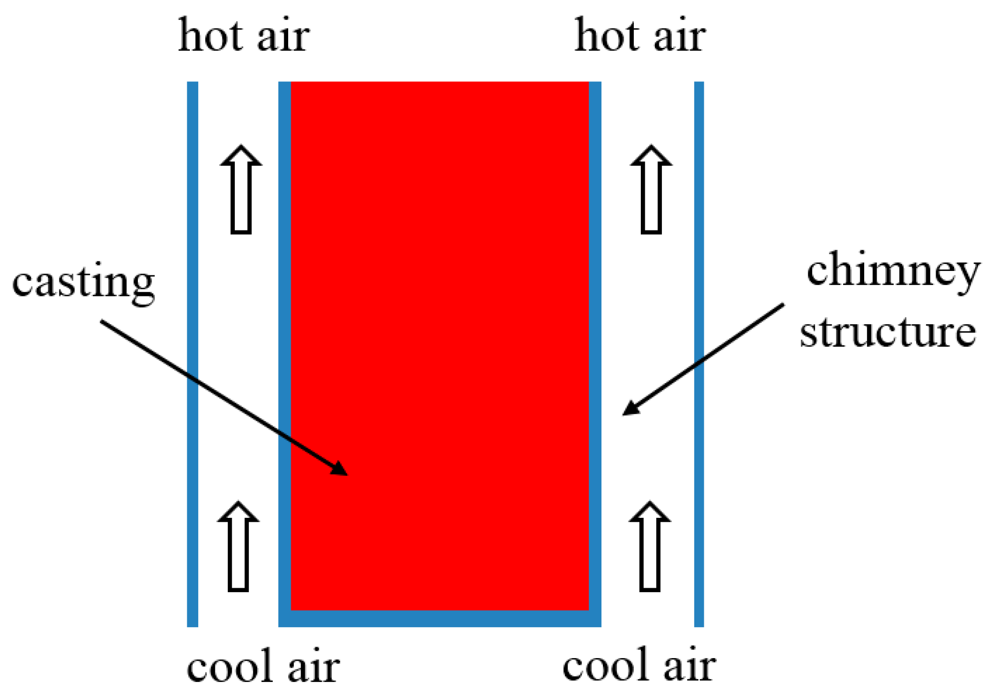
The chimney effect is a phenomenon in which air flows automatically along vertically tapered channels driven by the pressure difference between the top and bottom that resulted from the bottom heating. The chimney effect is mainly used for smoke exhaust in industrial production, construction, solar energy, and other fields [
21,
22,
23]. Babin et al. [
23] investigated the flow in a chimney, in which the simulation results showed that the inside pressure gradient and temperature gradient of the chimney determine the direction of hot dry air gases because of the variation in density of gas with respect to temperature change.
In the present study, a chimney structure of a hollow sand mold is proposed. The effect of the chimney structure on the A356 alloy specimen casting was investigated.
4. Heat Transfer Analysis in Chimney
For the convection in the channels, the Nusselt number is first calculated, and then, the convection coefficient
h can be calculated using the equation:
where
is the thermal conductivity of air, and
is the corresponding Nusselt number. The calculation of
is different for natural and forced convection.
- (1)
The calculation of Nusselt number under forced flow
In the convection in the chimney by forced flow, the Nusselt number is calculated as follows [
24]:
where
C is a constant,
is the Reynolds number, and
is the Prandtl number calculated by:
where
is the kinematic viscosity, and
α is the thermal diffusivity of the internal hot air:
where
is the specific heat of the internal hot air.
The Reynolds number is calculated as
The Nusselt number in a turbulent flow is calculated as [
24]:
- (2)
The calculation of Nusselt number under natural convection
For natural convection in the chimney, the Nusselt number is calculated by [
24]:
where
is the Grashof number, and
is the Rayleigh number calculated by [
24]:
where
is the coefficient of volumetric thermal expansion for ideal gas, and
is the sand mold surface temperature.
Therefore, the convection heat transfer in the chimney channels is related to the section size of the channels, the temperature of the channel wall, the height of the channel, and its orientation. Increasing the channel wall temperature, height, and section size can improve the chimney effect. For alloys of high melting points, such as cast steel, the chimney effect will be stronger. For big castings, this effect will be stronger.
Therefore, in the chimney structure, the heat flux between the sand mold and the air in the chimney is calculated by Equation (14):
If there was no chimney, the convection heat transfer from the mold wall to the environment is
Thus, it can be seen, in the chimney, that the internal air is heated up gradually from bottom to top compared to the fixed environment temperature. So, the temperature difference between the sand mold and air at the top of the chimney is reduced compared to the convection without the chimney, and then, the convective heat flux of the former is less than the latter. Therefore, it can be said that the cooling capacity of the chimney structure decreases from bottom to top, which is beneficial for the consequence of the casting.
5. Case Study: A Wedge Plate Specimen
For a wedge plate specimen, the influence of the chimney effect by natural and forced air cooling in the channels was studied. The casting process is illustrated in
Figure 4. The size of the casting was 300 × 200 × (10–40) mm.
Based on the STL file of the wedge plate casting, a hollow sand mold with a chimney structure was designed, as shown in
Figure 5. In the virtual heat transfer simulation, only the thermal properties of the aluminum casting were used, its thermal conductivity is 120 W/(m·K), specific heat is 1200 J/(kg·K), density is 2680 kg/m
3, latent heat is 556 kJ/kg, and the heat transfer coefficient of the casting to the environment is 5 W/(m
2·K). The connecting ribs were arranged between the shells of sand molds. They divided the chimney into a group of cooling channels with a cross-section of 16 × 16 mm. On the external surface, reinforcing ribs were added horizontally, surrounding the hollow mold to prevent cracks in the mold. A base plate was added at the bottom of the sand mold without sealing the cooling channels and played a supporting role for the mold during pouring. The external air temperature is 25 °C, the internal hot air temperature is supposed to be 400 °C, the air flow rate is 1 m/s, when the characteristic length
L = 16 mm. The frictional resistance coefficient
[
24], and the local resistance coefficient
[
24]; it is calculated that the chimney effect will only be effective when
H ≥ 0.011 m based on Equation (5). The cooling channels are higher than the required critical height; therefore, the chimney effect can play a role during the casting process.
Silica sand was used for 3D printing. Its composition is shown in
Table 1. The sand grains are clean, roughly round, and transparent with size ranging from 0.14 to 0.25 mm. According to the STL file, two hollow sand molds with chimneys and two traditional dense sand molds were printed by an ExOne-Smax 3D printing machine (ExOne, Gersthofen, Germany) with the binder sprayed on the designated areas of sand bed, as shown in
Figure 6. In addition, 1.6%–1.8% furan resin and 0.2% curing agent were used for the printing. The layer thickness was set to 0.25 mm. All molds were single piece with no division into copes and drags.
A traditional dense sand mold was designed for comparison. A geometric comparison of the traditional and hollow sand molds with chimneys is presented in
Table 2. The weight of the hollow sand mold was reduced by 23% compared to the dense sand mold.
The A356 aluminum alloy was melted in a crucible in an electrical resistance furnace; its composition is shown in
Table 3. Subsequently, the refining and degassing agents, mainly chlorine salts, were pressed into the liquid metal and treated for 5 min. The liquid metal at 700 °C was poured into the sand molds at 25 °C.
Two dense sand molds and two hollow sand molds were poured as two pairs for the casting experiment. One pair of the sand molds was cooled under natural convection. Meanwhile, a dense and a hollow sand mold for the different pairs were cooled differently with the former one cooled naturally and the latter one with forced air cooling from the bottom to enhance the chimney effect, P1DN means dense sand mold of Pair I under natural cooling, P1HN means hollow sand mold of Pair I with chimneys under natural cooling, P2DN means dense sand mold of Pair II under natural cooling, P2HN means hollow sand mold with chimneys of Pair II under forced cooling from bottom, as listed in
Table 4. The temperatures at the top, middle, and bottom of the castings and molds were measured by k-type thermocouples. The entire temperature distribution of the mold surface was obtained using an infrared imaging camera. These molds were placed on steel frames for air intake and air blow from the bottom. The on-site pouring experiments of the traditional and hollow sand molds are shown in
Figure 7, where an electric fan was placed 200 mm from the bottom of the P2HF mold to simulate an airflow with an air speed of 4 m/s at the entrance.
A thermal imaging camera (Flir 250, Boston, MA, USA) was used to record the temperature of the sand mold during the casting process. The residual stress of the castings was measured using a X-ray diffraction device (PROTO LXRD, Canada, CA, USA) in the up–down direction. The samples for the metallographic investigation were sliced in the middle in the direction parallel to the horizontal surface. The samples were ground and polished; then, scanning electron microscope (SEM) was performed using an optical microscope (KEYENCE VHX6000, Osaka, Japan). A field emission scanning electron microscope (ZEISS ULTRA 55, Oberkochen, Germany) equipped with energy-dispersive X-ray spectroscopy (EDS) was used to further observe the microstructures and perform composition analysis. Tensile tests were performed on the as-cast samples at room temperature using an universal testing machine (MTS E45.105, Minnesota, MN, USA) with a crosshead speed of 1 mm/min. The yield strength, ultimate tensile strength, and elongation of the samples were measured. Hardness measurements were performed using a Brinell hardness tester (Wolpert Wilson WH574, Norwood, MA, USA).
Figure 8 shows the sampling position of test specimens.
The specimens obtained from the middle parts of the casting were prepared under as-cast and heat treatment (T6). The T6 heat treatment comprises solution at 535 °C for 4.5 h and then quenching in a water bath at 60 °C, cooling at room temperature for 2 h, and finally, aging at 135 °C for 4 h [
25].
Author Contributions
Conceptualization, J.K. and H.S.; methodology, J.K. and H.S.; formal analysis, J.X., J.K., H.S., C.D., Y.H., J.Y. and W.M.; investigation, J.X., J.K., H.S., C.D., Y.H., J.Y. and W.M.; writing—original draft preparation, J.K. and J.X.; writing—review and editing, J.K. and J.X. All authors have read and agreed to the published version of the manuscript.
Funding
The project was funded by the National Natural Science Foundation of China (No. 51875308), Beijing Nature Sciences Fund-Haidian Originality Cooperation Project (L212002).
Institutional Review Board Statement
Not applicable.
Informed Consent Statement
Not applicable.
Data Availability Statement
Not applicable.
Conflicts of Interest
The authors declare no conflict of interest.
References
- Deng, C.; Kang, J.; Shangguan, H.; Hu, Y.; Huang, T.; Liu, Z. Effects of Hollow Structures in Sand Mold Manufactured Using 3D Printing Technology. J. Mater. Process. Technol. 2018, 255, 516–523. [Google Scholar] [CrossRef]
- Towoju, O.; Ishola, F. Numerical investigation of the variation of a uniformly dimensioned cast iron property using cooling channels. Mater. Today Proc. 2020, 46, 279–284. [Google Scholar] [CrossRef]
- Grassi, J.; Campbell, J.; Hartieb, M.; Major, F. The ablation casting process. Mater. Sci. Forum. 2009, 618, 591–594. [Google Scholar] [CrossRef] [Green Version]
- Salarvand, M.; Boutorabi, S.; Pourgharibshahi, M.; Tamizifar, M. Effect of Cooling Rate on the Microstructure and Mechanical Properties of High-Zinc AA 5182 Aluminum Wrought Alloy Cast by the Ablation Green Sand Mold Casting Process. Int. J. Met. 2021, 559, 1464–1475. [Google Scholar] [CrossRef]
- Satyam, S. Thermal Management and Solidification Characteristics in High Performance Aluminum Casting. Master’s Thesis, McMaster University, Hamilton, ON, Canada, 2016. [Google Scholar]
- Stets, W.; Petzschmann, U. Active cooling of resin bonded moulds to reduce the cooling time of heavy-section castings without loss of casting quality. In Proceedings of the 71st World Foundry Congress Advanced Sustainable Foundry, WFC 2014, Bilbao, Spain, 19–21 May 2014. [Google Scholar]
- Chhabra, M.; Singh, R. Rapid casting solutions: A review. Rapid Prototyp. 2011, 17, 328–350. [Google Scholar] [CrossRef]
- Hodder, K.; Chalaturnyk, R. Bridging Additive Manufacturing and Sand Casting: Utilizing Foundry Sand. Addit. Manuf. 2019, 28, 649–660. [Google Scholar] [CrossRef]
- González, P.; Valero, P.; Abia, A.; Sasstre, M.; Garcia, J. Feasibility of Calcium Sulfate Moulds Made by Inkjet 3D Printing for Rapid Casting of Aluminium Alloys. Metals 2020, 10, 802. [Google Scholar] [CrossRef]
- Lee, J.; An, J.; Chua, C. Fundamentals and applications of 3D printing for novel materials. Appl. Mater. Today. 2017, 7, 120–133. [Google Scholar] [CrossRef]
- Zeng, G.; Song, T.; Dai, Y.; Tang, H.; Yan, M. 3D printed breathable mould steel: Small micrometer-sized, interconnected pores by creatively introducing foaming agent to additive manufacturing. Mater. Design 2019, 169, 107693. [Google Scholar] [CrossRef]
- Chhabra, M.; Singh, R. Experimental Investigation for the Hardness of Castings Produced by Using ZCast Process. Trans. Indian Inst. Met. 2018, 71, 153–166. [Google Scholar] [CrossRef]
- Snelling, D.; Williams, C.; Druschitz, A. Mechanical and material properties of castings produced via 3D printed molds. Addit. Manuf. 2019, 27, 199–207. [Google Scholar] [CrossRef]
- Snelling, D.; Li, Q.; Meisel, N.; Williams, C.; Batra, R.; Druschitz, A. Lightweight Metal Cellular Structures Fabricated via 3D Printing of Sand Cast Molds. Adv. Eng. Mater. 2015, 17, 923–932. [Google Scholar] [CrossRef]
- Yang, L.; Harrysson, O.; Cormier, D.; West, H.; Gong, H.; Stucker, B. Additive Manufacturing of Metal Cellular Structures: Design and Fabrication. Met. Materials Soc. 2015, 67, 608–615. [Google Scholar] [CrossRef]
- Wang, J.; Sama, S.; Manogharan, G. Re-Thinking Design Methodology for Castings: 3D Sand-Printing and Topology Optimization. Int. J. Met. 2019, 13, 2–17. [Google Scholar] [CrossRef]
- Sama, S.; Badamo, T.; Lynch, P.; Manogharan, G. Novel Sprue Design in Metal Casting via 3D Sand-Printing. Addit. Manuf. 2019, 25, 563–578. [Google Scholar] [CrossRef]
- Shangguan, H.; Kang, J.; Yi, J.; Zhang, X.; Wang, X.; Wang, H.; Huang, T. The design of the 3D printed lattice reinforced thickness-varying shell mold for casting. Materials 2018, 11, 535. [Google Scholar] [CrossRef] [Green Version]
- Shangguan, H.; Kang, J.; Deng, C. 3D-printed shell-truss sand mold for aluminum castings. J. Mater. Process. Technol. 2017, 250, 247–253. [Google Scholar] [CrossRef]
- Kang, J.; Shangguan, H.; Deng, C.; Hu, Y.; Yi, J.; Wang, X.; Zhang, X.; Huang, T. Additive manufacturing-driven mold design for castings. Addit. Manuf. 2018, 22, 472–478. [Google Scholar] [CrossRef]
- Ghanbari, M.; Rezazadeh, G. Chimney for air ventilation of metropolises. Atmos. Pollut. Res. 2019, 10, 462–473. [Google Scholar] [CrossRef]
- Nasraoui, H.; Driss, Z.; Kchaou, H. Effect of the chimney design on the thermal characteristics in solar chimney power plant. J. Therm. Anal. Calorim. 2020, 140, 2721–2732. [Google Scholar] [CrossRef]
- Babin, T.; Ramanathan, S.; Muthukumar, S.; Arun, A.; Subbiah, S. Numerical investigation of backflow in natural draft chimneys. Mater. Today Proc. 2021, 45, 1196–1204. [Google Scholar] [CrossRef]
- Tao, W. Numerical Heat Transfer; Xi’an Jiaotong University Press: Xi’an, China, 2001. [Google Scholar]
- Peng, J.; Tang, X.; He, J.; Xu, D. Effect of heat treatment on microstructure and tensile properties of A356 alloys. Trans. Nonferrous Met. Soc. China 2011, 21, 1950–1956. [Google Scholar] [CrossRef]
- Caeres, C.; Rovera, D. Solid solution strengthening in concentrated Mg-Al alloys. J. Light Met. 2001, 1, 151–156. [Google Scholar] [CrossRef]
- Zhu, M.; Jian, Z.; Yang, G.; Zhou, Y. Effects of T6 heat treatment on the microstructure, tensile properties, and fracture behavior of the modified A356 alloys. Mater. Des. 2012, 36, 243–249. [Google Scholar] [CrossRef]
Figure 1.
Schematic of the chimney structure.
Figure 2.
Schematic of a typical chimney structure of sand mold for casting. (a) Horizontal cross-section, (b) Vertical cross-section.
Figure 3.
Design flowchart for chimney structure.
Figure 4.
Schematic of the wedge-shaped plate casting and its sand mold with the chimney. (a) Wedge-shaped plate casting and (b) sand mold with the chimney (unit: mm).
Figure 5.
Designed hollow sand mold with chimneys: (a) overall perspective view and (b) partial sectional view (unit: mm).
Figure 6.
Sand mold fabricated by 3D printing: (a) traditional dense sand mold and (b) hollow sand mold with chimneys.
Figure 7.
On-site pouring experiments: (a) natural cooling and (b) forced cooling. (C1 is the test point at the top of the molds, 30 mm from the top of the molds, C2 is the test point at the bottom of the molds, 30 mm from the bottom of the molds.)
Figure 8.
Schematic for the sampling position of the casting specimen. (S1 is the test point at the top of the castings, 50 mm from the top of the castings, S2 is the test point at the middle of the castings, S3 is the test point at the bottom of the castings, 50 mm from the bottom of the castings.)
Figure 9.
Infrared images of the sand mold during the casting process at (a) 2500 s, (b) 6000 s, (c) 2500 s, and (d) 6000 s.
Figure 10.
Temperature curve of SP2 (
Figure 9) of the sand mold.
Figure 11.
Temperature gradient between the top (SP1) and bottom (SP3) of the sand mold.
Figure 12.
(a) Cooling curves of points C1 and C2 of the castings, (b) Temperature gradient between C1 and C2 of the castings.
Figure 13.
Optical micrographs of the castings under different conditions. (a) As-cast-P1DN, (b) T6-P1DN, (c) As-cast-P1HN, (d) T6-P1HN, (e) As-cast-P2HF, (f) T6-P2HF.
Figure 14.
Mechanical properties of A356 alloys with different sand mold and heat treatments. (a) Tensile strength (Rm), (b) yield strength (Rp 0.2), (c) elongation (EL), and (d) hardness.
Figure 15.
Comparison of temperature and temperature gradient of three groups of sand mold and casting.
Figure 16.
Schematic diagram of the improved chimney structure.
Table 1.
Composition of the sand used for 3D printing.
| Composition | SiO2 | Al2O3 | TiO2 | FeO3 |
|---|
| Content (%) | 99.1 | 0.22 | 0.21 | 0.085 |
Table 2.
Comparison of the traditional mold and hollow mold with chimneys.
| | Dense Sand Mold | Hollow Sand Mold with Chimneys |
|---|
| Shell Thickness (mm) | One layer: 40 | Two layers: 12 + 12 |
| Size of the Lattice Support between Shells (mm) | - | 16 × 16, spacing 10 |
| Size of External Reinforcement Ribs | - | 10 × 10, spacing 60 |
| Weight (kg) | 12.93 | 9.92 |
| Weight Reduction Rate (%) | - | 23 |
Table 3.
Composition of A356 alloy.
| Composition | Si | Mg | Fe | Cu | Zn | Ti | Mn | Al |
|---|
| Content (%) | 6.5–7.5 | 0.25–0.45 | 0.12 | 0.05 | 0.05 | 0.08–0.2 | 0.05 | Base |
Table 4.
Casting experiment scheme.
| Scheme No. | Pair No. | Sand Mold Type | Cooling Condition |
|---|
| P1DN | Pair I | Dense sand mold | Natural cooling |
| P1HN | Hollow sand mold with chimneys | Natural cooling |
| P2DN | Pair II | Dense sand mold | Natural cooling |
| P2HF | Hollow sand mold with chimneys | Forced cooling from bottom |
Table 5.
Residual stress of three castings.
| Scheme No. | Residual Stress (MPa) |
|---|
| S1 | S2 | S3 |
|---|
| P1DN | −19.26 | 6.87 | −66.92 |
| P1HN | −28 | 58.87 | −55.87 |
| P2HF | −185 | 97.26 | −71.35 |
Table 6.
EDS results of the three castings.
| Element (wt %) | P1DN | P1HN | P2HF |
|---|
| Al | 98.18 | 98.01 | 97.73 |
| Si | 1.67 | 1.72 | 2.01 |
| Mg | 0.07 | 0.24 | 0.20 |
| Cu | 0.09 | 0.04 | 0.05 |
| Publisher’s Note: MDPI stays neutral with regard to jurisdictional claims in published maps and institutional affiliations. |
© 2022 by the authors. Licensee MDPI, Basel, Switzerland. This article is an open access article distributed under the terms and conditions of the Creative Commons Attribution (CC BY) license (https://creativecommons.org/licenses/by/4.0/).


 ,
, 


