Article

Wear Resistance of FeCrAlNbNi Alloyed Zone via Laser Surface Alloying on 304 Stainless Steel

1
Science and Technology on Electronic Test and Measurement Laboratory, North University of China, Taiyuan 030051, China
2
School of Materials Science and Engineering, Harbin Institute of Technology, Harbin 150080, China
3
School of Materials Science and Engineering, North University of China, Taiyuan 030051, China
4
School of Materials Science and Engineering, Jiangsu University, Zhenjiang 212013, China
5
Institute of Advanced Manufacturing and Modern Equipment Technology, Jiangsu University, Zhenjiang 212013, China
6
School of Mechanical Engineering, Jiangsu University, Zhenjiang 212013, China
7
Laboratory of Materials Welding and Joining, School of Materials Science and Engineering, University of Science and Technology Beijing, Beijing 100083, China
8
Shi-Changxu Innovation Center for Advanced Materials, Institute of Metal Research, Chinese Academy of Sciences, Shenyang 110016, China
*
Authors to whom correspondence should be addressed.
Metals 2022, 12(3), 467; https://doi.org/10.3390/met12030467
Submission received: 9 January 2022 / Revised: 3 February 2022 / Accepted: 8 March 2022 / Published: 10 March 2022
(This article belongs to the Special Issue Additive Manufacturing of Metals with Lasers II)

Abstract

:
In order to enhance the wear resistance of 304 stainless steel, a FeCrAlNbNi alloyed zone (AZ) was deposited on its surface using laser surface alloying technology, and the wear resistance of the AZ was investigated. The results found that the AZ had a dense and fine structure and no obvious defects, and the microstructure was mainly composed of equiaxed dendrites. A large amount of iron compounds and iron-based solid solutions in the AZ made the average microhardness of the AZ about 2.6 times higher than of the substrate. The friction and wear performance of the AZ at 25 °C, 200 °C, 400 °C and 600 °C better than that of the substrate. As far as the AZ was concerned, the abrasion resistance was the best under normal temperature environment. At 200 °C and 400 °C, due to the repeated extrusion and grinding of the friction pair, the oxide layer formed on the AZ surface was prone to microcracks and peeling off, which reduces the wear resistance. Especially at 400 °C, the formation and peeling speed of the oxide layer is accelerated, and the wear resistance is the lowest. However, when the temperature reached 600 °C, an Al2O3 layer was formed. And the Al2O3 has greater wear resistance to protect the AZ. At this time, the wear resistance was greatly improved compared to 200 °C and 400 °C. Therefore, as the temperature increased, the wear resistance of the AZ first decreased and then increased.

1. Introduction

304 stainless steel ball valve is an important pressure-bearing part. Because of its good sealing performance and simple operation, it has been widely used in oil and power pipeline systems. Although 304 stainless steel has excellent strength, it has poor high temperature wear resistance. This shortcoming reduces the service life of the ball valve in a wide temperature range and limited its application as an important moving part in engineering [1,2,3]. To optimize the wear performance of the material, many researchers use laser surface modification technology to prepare alloy layer on the surface of stainless steel, so that the wear resistance of its surface can achieve the desired effect. Compared with surface modification technologies such as physical vapor deposition [4] and supersonic flame [5,6,7], laser prepare alloy layer has the advantages of metallurgical bonding and small heat-affected zone [8,9,10,11]. At present, laser surface modification has been used as an effective technology to enhance the hardness and wear resistance of metal substrates.
Ouyang et al. [12] prepared Ni60-TiC-WS2 composite coating on the surface of 304 stainless steel using laser cladding surface modification technology, and the wear resistance of composite coatings and substrates and their related wear mechanisms have been systematically studied under different temperature environments. The results found that the wear performance of the composite coating at different temperatures was greatly improved compared with that of the substrate. Jin et al. [13] prepared FeNiCoAlCu alloy coating on steel by laser surface modification technology. It was found that the alloy coating has good wear performance at high temperatures, which was mainly due to the formation of a dense protective oxide film during wear. The wear mechanism was mainly abrasive wear and oxidative wear. Tang et al. [14] studied the wear properties of laser cladding new-type medium-entropy high-speed steel (ME-HSS) coatings. Compared with the W6Mo5Cr4V2 coating, the newly designed ME-HSS coating contained high content of Co, Ni and Al and other anti-oxidation elements. It was easier to form a continuous and dense oxide film on the worn surface in a high temperature environment, thereby further enhancing the wear resistance. In summary, researchers have conducted extensive research on enhancing the wear resistance of steel, but there are currently few studies on enhancing the wear resistance of steel in a wider temperature range.
FeCrAlNbNi alloy coating is easy to form a protective aluminum oxide layer at high temperature, and at the same time, Nb reduces the consumption of Al [15], so that the oxidation rate is reduced, and Ni improves the high-temperature plasticity of the alloy coating and is beneficial to industrial production. Therefore, the FeCrAlNbNi alloy material has better high temperature resistance [9,10,11,12,13,14,15,16].
Based on this, this article uses laser alloying technology to deposit FeCrAlNbNi alloyed zone (AZ) on the surface of the 304 stainless steel substrate. The wear resistance of the AZ and the substrate were studied under different temperature environments. The wear mechanism of the FeCrAlNbNi AZ at different temperatures was analyzed. Provide a new idea for the development of wear-resistant materials.

2. Experiment

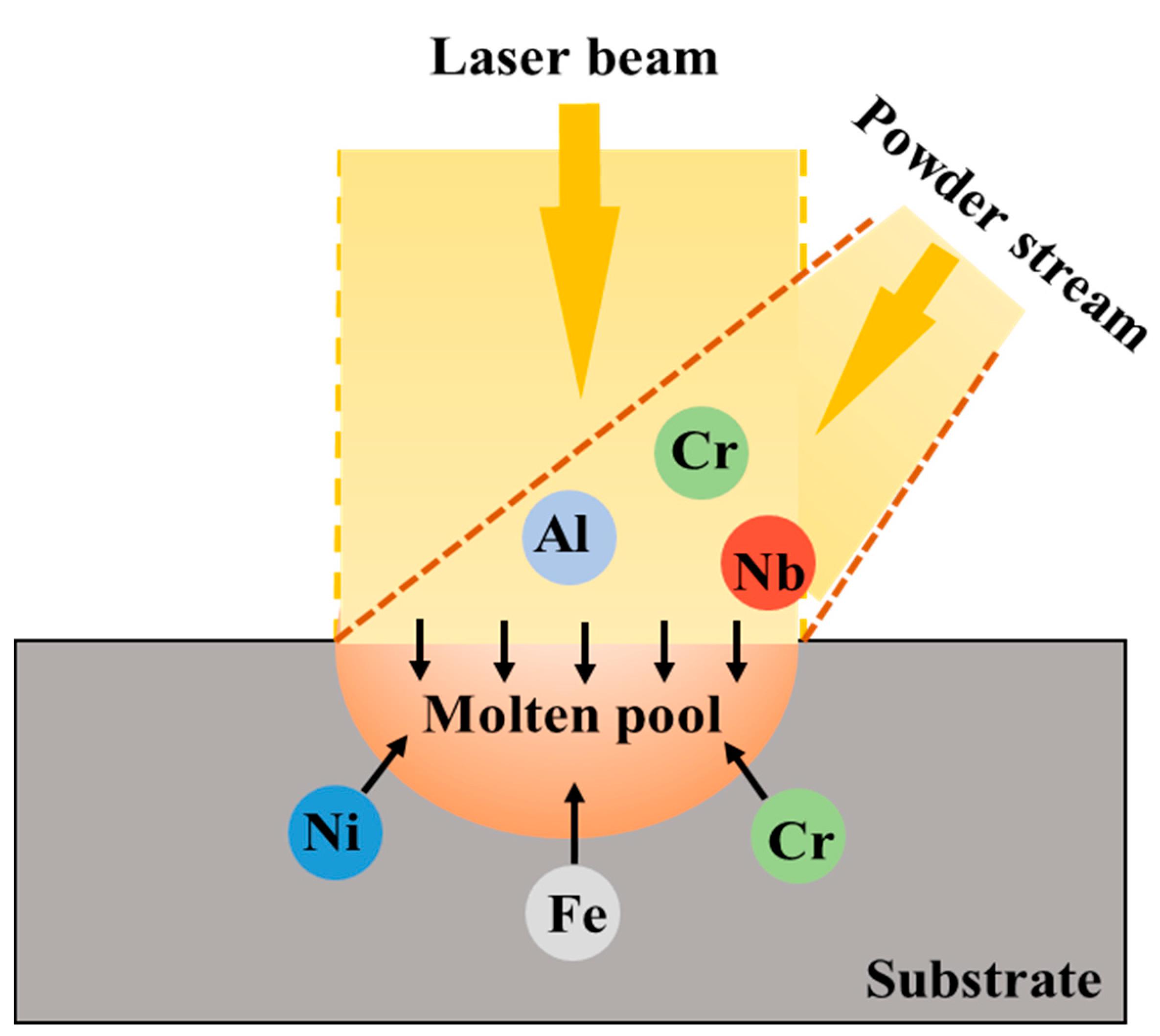
2.1. Preparation of the Simples

The FeCrAlNbNi AZ was prepared through laser surface alloying technology. The substrate was 304 stainless steel with an original size of 20 mm × 20 mm × 10 mm. The element content of the substrate is shown in Table 1. The cladding material was Nb-Al-Cr mixed powder (chemical composition wt.%: Nb50, Al40, Cr10). Using the dilution effect of laser surface alloying, Fe, Cr, and Ni were obtained from 304 stainless steel (Figure 1). A fiber-coupled semiconductor laser (LDF.4000-100, Continuous wave with a wavelength of 980 nm–1020 nm, Laserline Gmbh, Mülheim-Kärlich, Germany) equipped with a DMS-3 powder feeder was used to deposit the FeCrAlNbNi AZ. To avoid oxidation of the molten metal during the alloying process, argon gas was used as the protective gas. The parameters of the laser alloying process are shown in Table 2.

2.2. Material Characterization

The phase analysis of AZ was carried out by X-ray diffraction (XRD, D/Max2500PC, Rigaku, Tokyo, Japan) from 20° to 90° with Cu-Kα radiation at 40 kV and 300 mA at a scanning rate of 4° min−1. Scanning electron microscopy (SEM, S3400N, HITACHI, Tokyo, Japan) and equipped energy dispersive spectroscopy (EDS) were used to characterize the morphology and element distribution of the AZ.

2.3. Performance Test

The HVS-1000 micro Vickers hardness tester was used to test the microhardness distribution of the AZ section. During the experiment, the loading load was 200 g, and the loading time was 15 s. Along the cross section of AZ, test 3 times at an interval of 0.1 mm from the surface to the inside, and calculate the average value.
The HT-1000 high-temperature friction and wear tester was used to carry out friction and wear experiments of the AZ at different temperatures of 25 °C, 200 °C, 400 °C, and 600 °C. The experimental load was 5 N, the friction radius was 3 mm, the speed was 500 r/min, and the wear time was 30 min. The friction pair material was a Si3N4 ceramic ball with a diameter of 5 mm. The MT-500 probe type material surface wear scar measuring instrument was used to measure the two-dimensional morphology of the cross-section after wear.

3. Results and Discussion

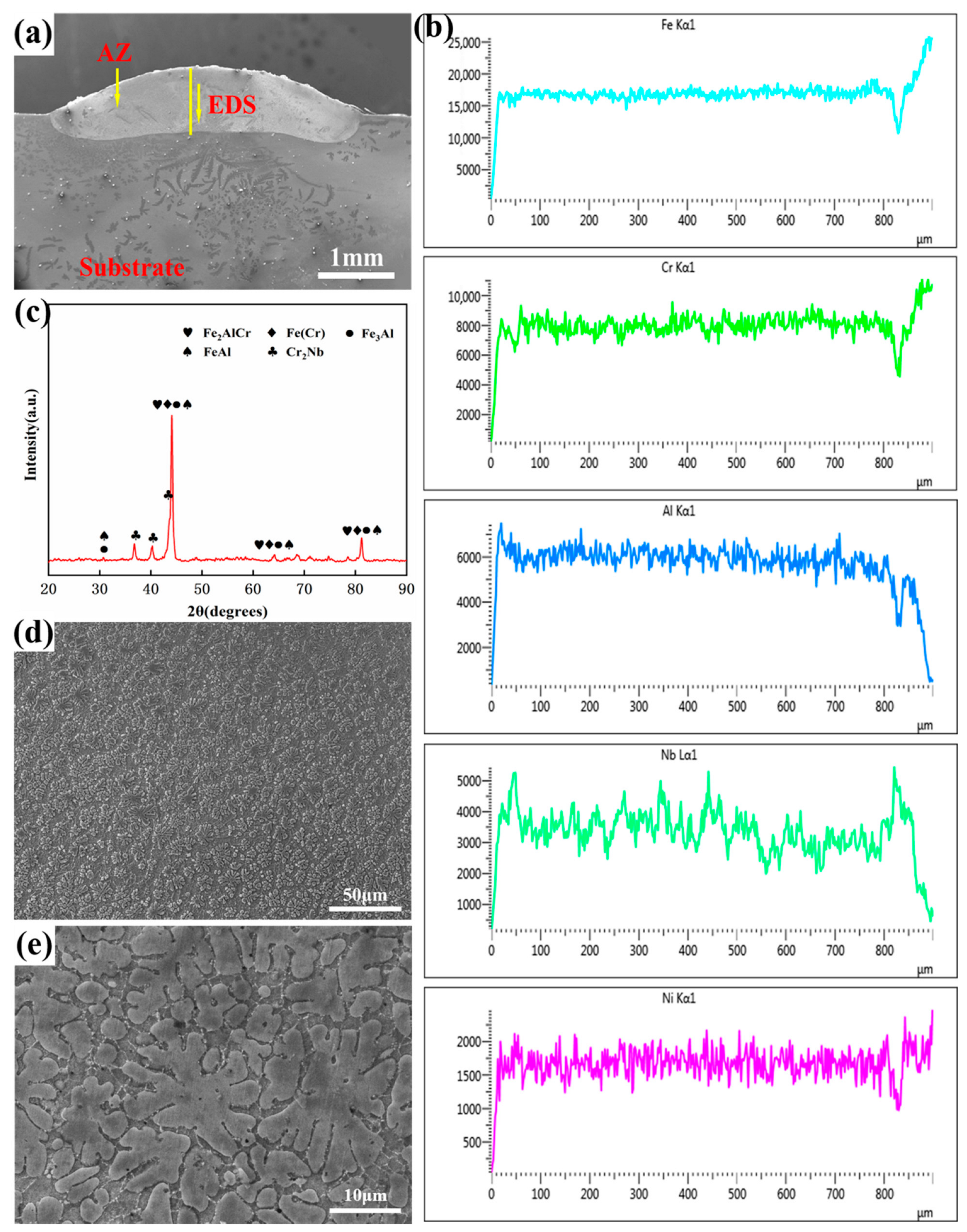
3.1. Macro Morphology and Micro Analysis of the AZ

Figure 2 shows the internal structure of the AZ. From the cross-sectional morphology of single-pass, it can be found that the AZ structure is compact and has no obvious defects, and the lower part of the AZ overlaps with the substrate. The reason for overlaps is that when the powder melts under the action of laser, the surface of the substrate also melts, leading to the mixing of substrate elements and powder elements and forming alloying zone. The EDS line scan result (Figure 2b) in Figure 2a shows that the AZ contains a large amount of Fe, Cr, Al, Nb, and Ni, indicating that the AZ has formed the FeCrAlNbNi alloyed zone as expected. The analysis of phase composition (Figure 2c) shows that the alloyed AZ contains Fe2AlCr, FeAl, Fe3Al, Cr2Nb, and Fe (Cr) phases. The Fe3Al, FeAl, and Cr2Nb phases are intermetallic compounds with high hardness and low toughness, and excellent high-temperature performance, which plays a certain positive role in enhancing the wear resistance of AZ. The characteristic peak of Fe2AlCr indicates that Fe2AlCr is a single-phase iron-based solid solution [9]. Fe2AlCr and Fe (Cr) solid solutions effectively alleviate the brittleness problem of the AZ at room temperature [9]. Figure 2d,e show that the AZ is mainly composed of equiaxed dendrites, which is mainly caused by the rapid cooling during the laser alloying process [17]. The rapid cooling of laser surface alloying can effectively refine the crystal grains, which has a certain positive effect on the improvement of the mechanical properties of the AZ.

3.2. Microhardness

Figure 3 shows the cross-sectional hardness distribution of the AZ. The average microhardness of AZ is 605.7 HV0.2, which is about 2.6 times higher than of the substrate. The main reason for the increase in the AZ microhardness is the existence of high hardness phases of Fe3Al, FeAl, and Cr2Nb, and the solid solution strengthening of iron-based solid solutions. At approximately 900 μm from the top, the microhardness of the AZ drops to about 432 HV0.2. This is because in the laser alloying process, the non-equilibrium reaction of rapid melting and solidification leads to insufficient growth of the grains at the bottom of the AZ, resulting in a large number of honeycomb grains and fewer columnar grains [18]. However, the hardness value of other areas of the AZ did not change much, indicating that the phase composition and grain morphology distribution were relatively uniform. In addition, the microhardness of the heat-affected zone (HAZ) is reduced. This is because the cooling rate of the HAZ exceeds the critical cooling rate of hardening of the substrate, resulting in a martensitic structure [19]. According to the damage theory, martensitic transformation results in the deterioration of mechanical properties, especially microhardness [20].

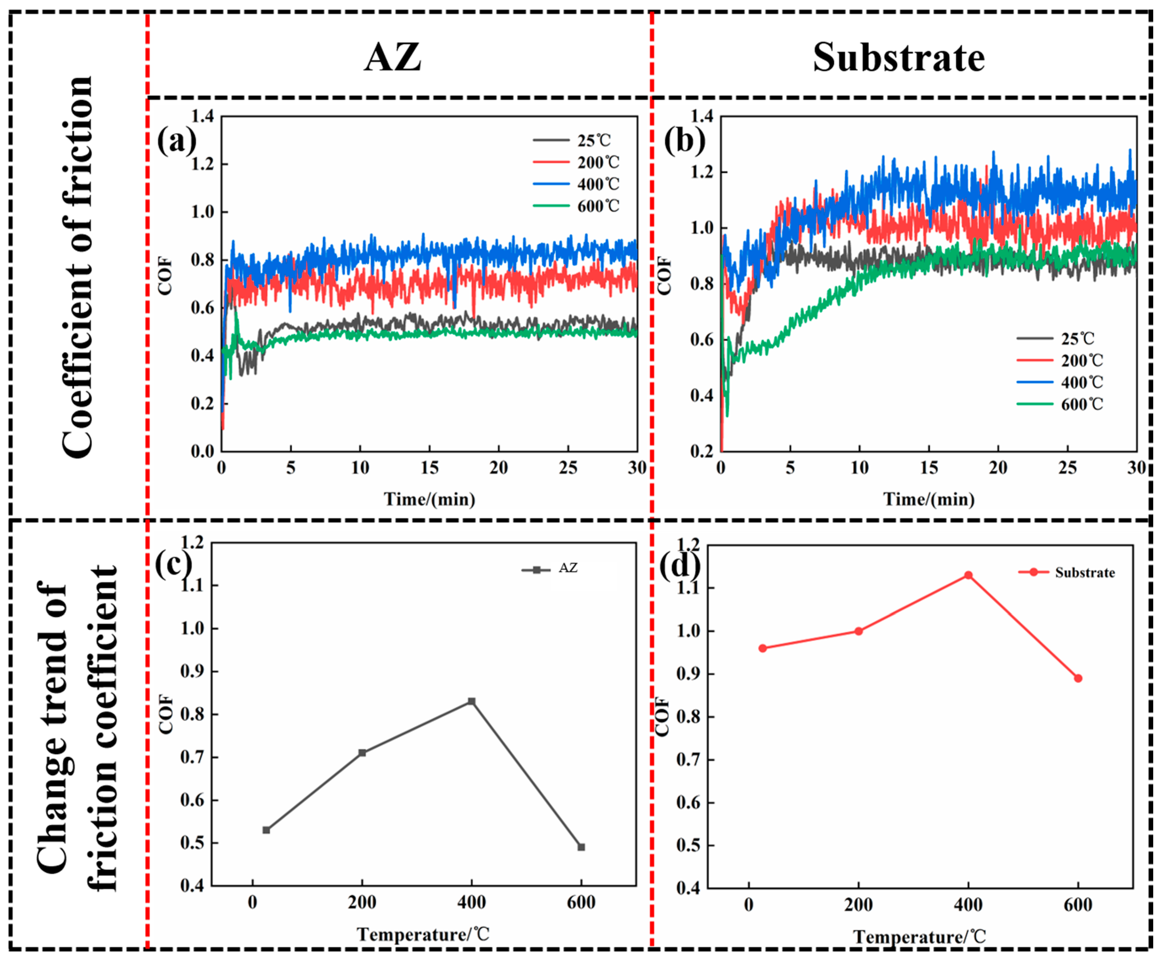
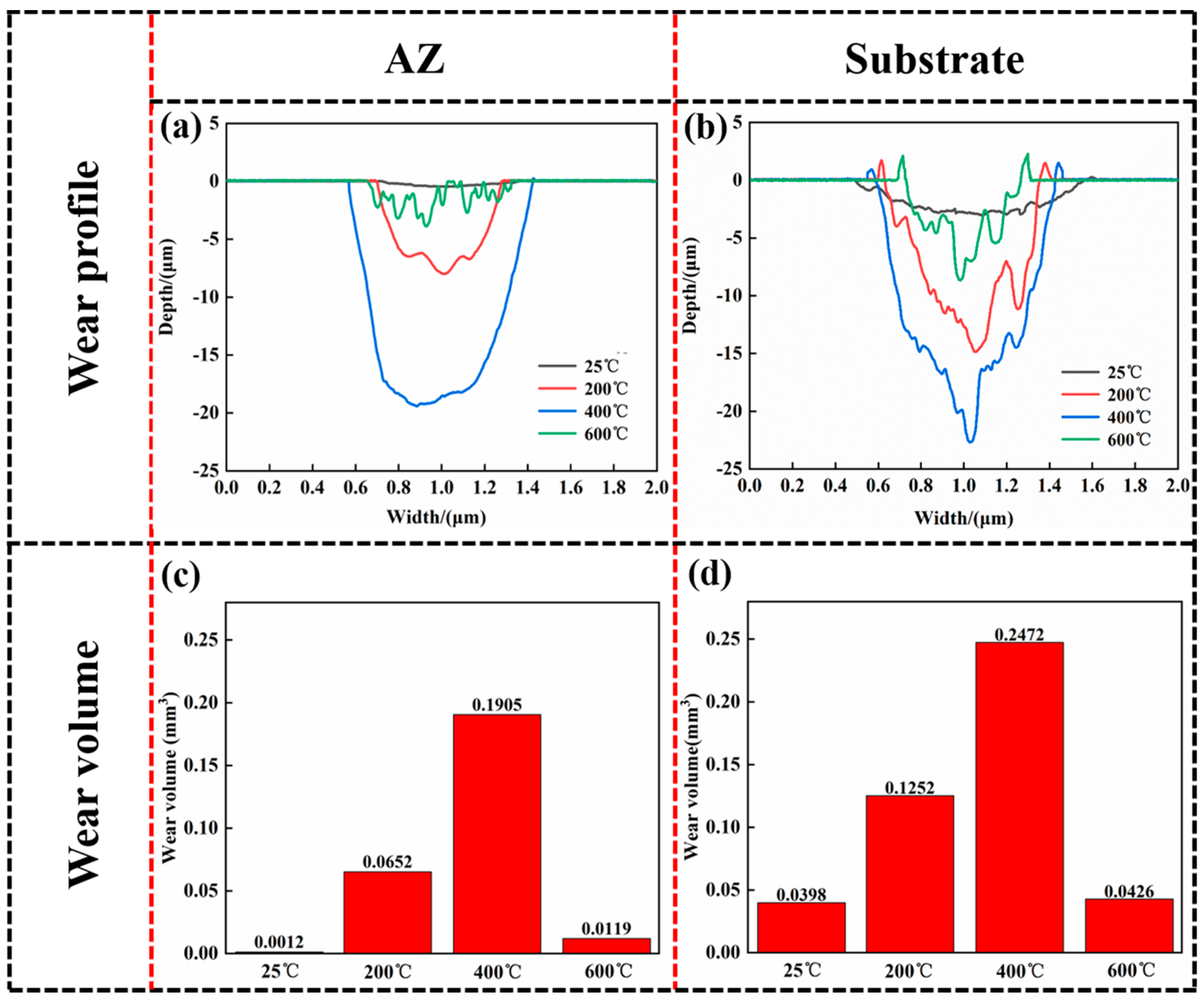
3.3. Friction Coefficient and Wear Volume

Figure 4 gives the coefficients of friction (COF) of the AZ and 304 stainless steel substrate at 25 °C, 200 °C, 400 °C and 600 °C. It can be found from Figure 4a that the friction coefficient of the AZ gradually stabilized after 5 min, and the average friction coefficients were 0.53, 0.71, 0.83 and 0.49 at 25 °C, 200 °C, 400 °C and 600 °C, respectively. In Figure 4b, the friction coefficient of the substrate gradually stabilized after 10 min, and the average friction coefficient was 0.96, 1.0, 1.13 and 0.89 at 25 °C, 200 °C, 400 °C and 600 °C, respectively. It can be seen that the COF of the AZ is lower than that of the substrate at different temperatures. In Figure 4c,d, the COF of the AZ and the substrate show a first increase and then decrease with the increase of temperature. The trend indicates that temperature has a greater influence on the wear resistance of the AZ and the substrate. Both the AZ and the substrate have different wear resistance under different temperature environments. Figure 5 displays the wear profile and volume of the AZ and 304 stainless steel. The wear profile and volume of the AZ at different temperatures are smaller than the substrate. The friction coefficient and the wear volume reflect the wear resistance of the sample to a certain extent [21,22]. Combined with the comparison result of the friction coefficient in Figure 4 show that the AZ has better abrasion resistance than the substrate under the different temperature environment. This is because the intermetallic compound phase and solid solution phase formed in the AZ improve the wear resistance, and the rapid heating and rapid cooling during the alloying process has the effect of refining the grains, which is also the reason why the wear resistance may be improved.
The change trend of the wear profile area and wear volume with temperature is the same as the friction coefficient, that is, it first increases and then decreases, indicating that the wear resistance the AZ and the substrate first decreases and then increases. For the AZ, at 400 °C, the friction coefficient and wear volume are 0.83 and 0.1905 mm3, respectively, while the friction coefficient and wear volume of the AZ are only 0.49 and 0.0119 mm3 at 600 °C. It is much lower than when the temperature is 400 °C. This is because an oxide film with solid lubricating effect is appeared on the worn surface under the environment of 600 °C. However, due to the relatively low temperature in the environment of 200 °C and 400 °C, the wear-resistant oxide film is not formed, resulting in a decrease in wear resistance. Therefore, in a high temperature environment, the AZ has relatively better wear resistance at 600 °C. The wear volume of the AZ at room temperature (25 °C) is smaller than that at 600 °C, but the friction coefficient is slightly greater than that of the AZ at 600 °C. This is because the oxide film formed on the worn surface of the AZ under an environment of 600 °C has a better lubricating effect, making the friction coefficient smaller. Due to the wear volume of the AZ is smaller in the normal temperature environment, and the profile of the wear section is flatter, the wear resistance of the AZ in the normal temperature environment is better.

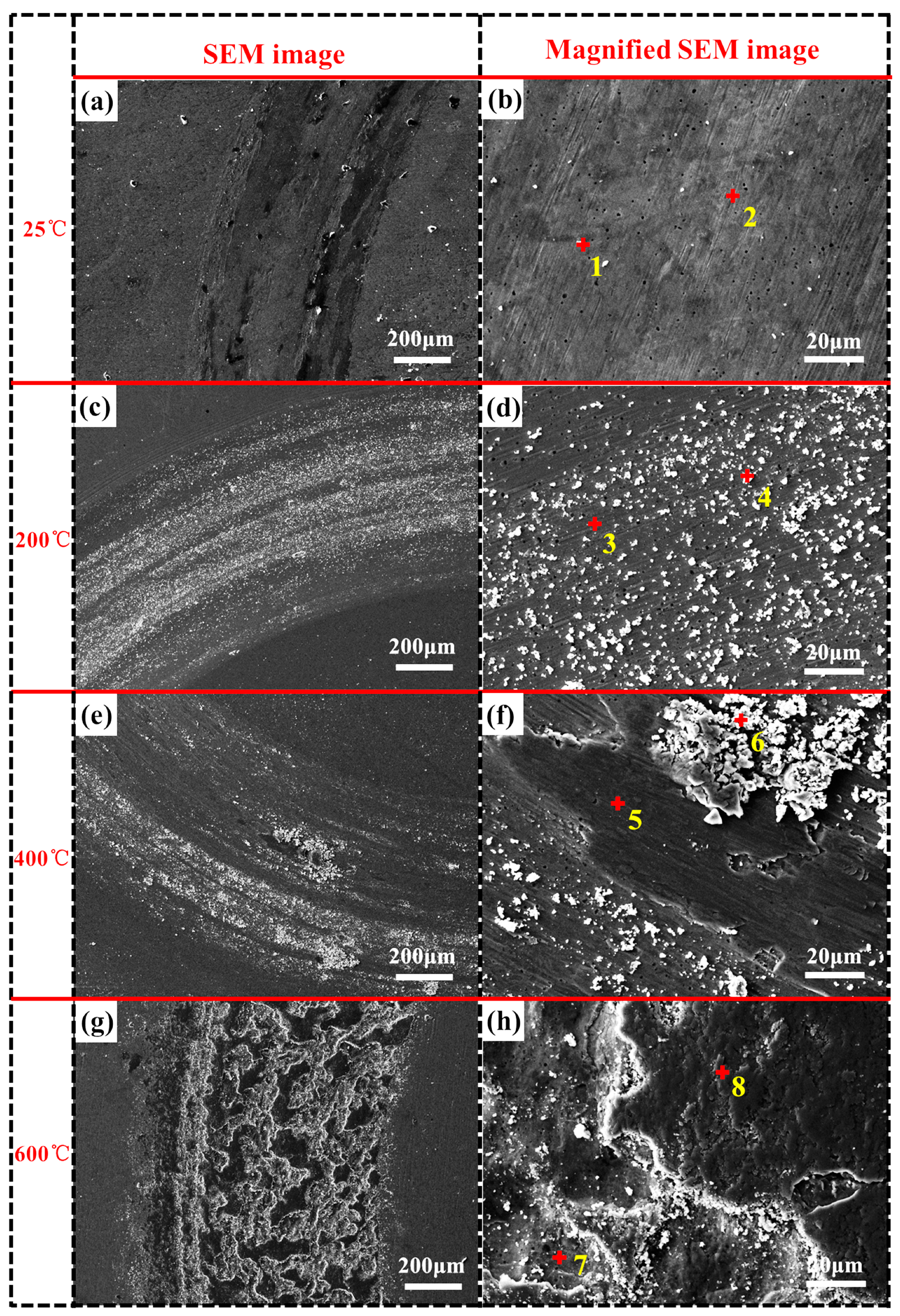
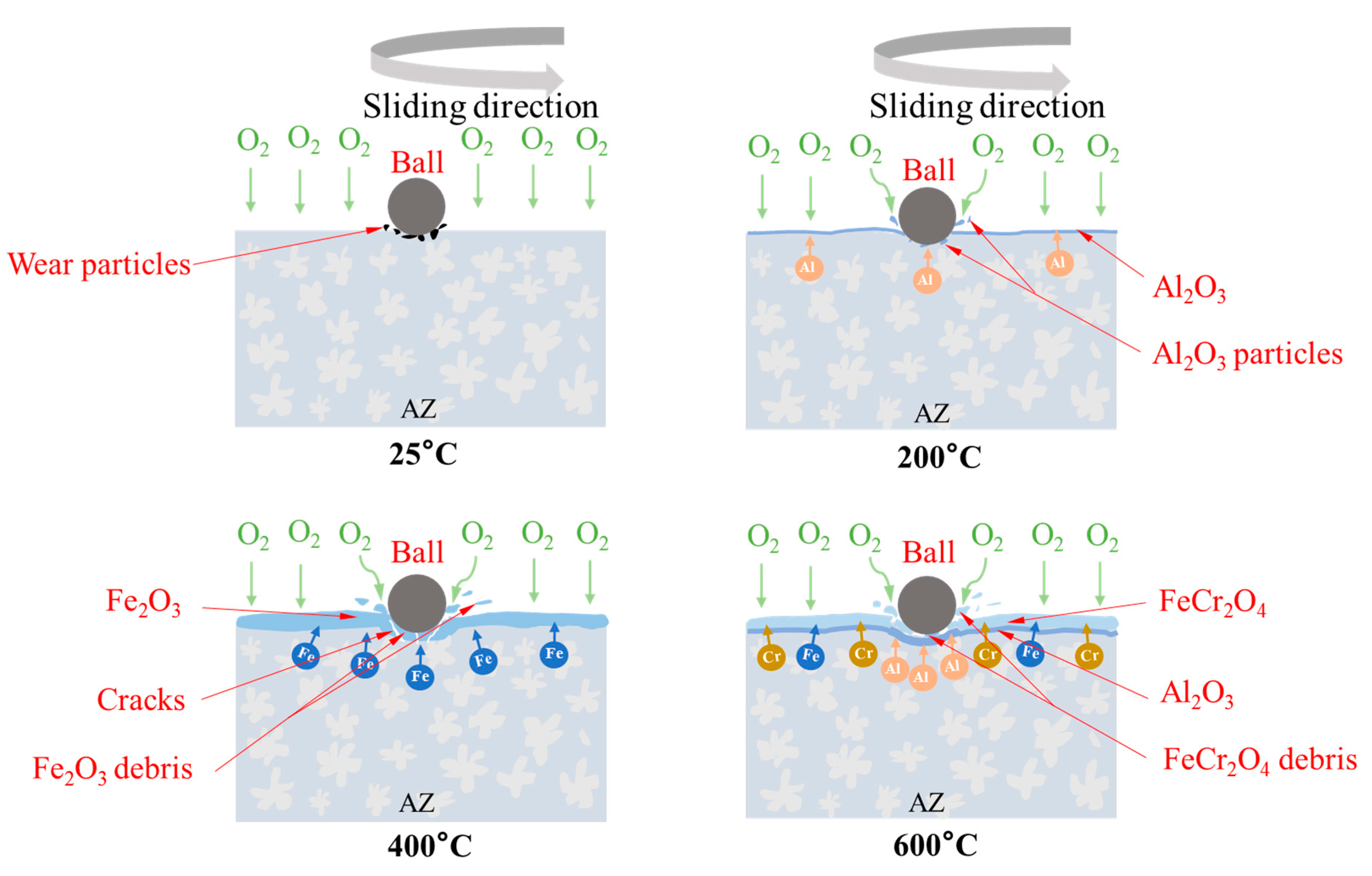
3.4. Wear Mechanism of the AZ

Figure 6 shows the wear morphology of the AZ. Table 3 gives the EDS results in Figure 6. Figure 6a,b are the worn surface morphology at 25 °C. It can be found that the worn surface is relatively flat, with a small amount of wear particles and fine grooves. The content of O element in the wear particles is higher, which may be due to the heat generated by friction during the wear process, and thus the mixed oxides are generated. Oxides are used as wear particles to squeeze on the AZ surface to form furrows. At this time, the wear mechanism is abrasive wear. When the temperature is 200 °C (Figure 6c,d), a large number of smaller wear particles and grooves appear on the wear surface, and the wear mechanism is abrasive wear. According to EDS analysis, the main component of the wear particles is Al2O3. This is due to the selective oxidation of Al such that O2 preferentially reacts with Al on the worn surface. The O element content in the groove area of the wear surface is low, indicating that the degree of oxidation is low. The formed Al2O3 does not improve the wear resistance, but mainly acts as wear particles during the wear process. Because the Al2O3 layer formed during the wear process is constantly destroyed, and then new Al2O3 is not generated in time due to the low temperature, and the wear particles (Al2O3) have a higher hardness, which accelerates the wear of the AZ. At 400 °C (Figure 6e,f), the groove becomes larger, and due to the extrusion of the worn surface, superimposed layered fragments appear. The layered fragments are loose and partially peeled off, indicating that the surface of the AZ is plastically deformed and adhesively worn. The initially formed Al2O3 has been completely destroyed due to the wear deepening, and then a large amount of Fe elements are oxidized. According to EDS analysis, the wear surface is mainly Fe2O3, and the wear debris is also Fe2O3. Under the repeated extrusion and grinding of the friction pair, the contact between the fragments and the AZ surface will destroy the oxide film formed on the AZ surface, and it is easy to produce microcracks and peel off. At the same time, the surface elements are more active at high temperatures. It reacts with oxygen to form oxides, and then microcracks are formed on the oxide surface. This cycle accelerates wear, which greatly reduces wear resistance and increases COF. The wear mechanism is mainly abrasive wear, adhesive wear and oxidative wear. At 600 °C (Figure 6g,h), a lot of layered fragments emerged on the worn surface, showing slight plastic deformation and adhesive wear. EDS analysis results show that the layered fragments are FeCr2O4, which is a bimetallic oxide formed by Cr2O3 and Fe, and its relational formula is: 2Cr2O3 + 2Fe + O2→2FeCr2O4. The spontaneity of the reaction was evaluated using the standard Gibbs free energy of formation ( Δ f G 0 ) at 600 °C, calculated from the equation [23]:
Δ G 0 = Σ v p r o d u c t Δ f G 0 ( p r o d u c t ) Σ v r e a c t a n t Δ f G 0 ( r e a c t a n t )
where v represents the coefficients of products and reactants. At the same time, it had been proved in the literature [24] that the reaction can proceed spontaneously at 600 °C. FeCr2O4 improves the lubricating effect of the oxide film. In a high temperature environment, the lubricating effect of bimetallic oxides is better than that of single metal oxides, so the COF of AZ is smaller at 600 °C [25]. At 600 °C, Al diffusion accelerates, so the surface after the layered fragments fall off is Al2O3 and no damage is observed. Al2O3 has a higher hardness, which protects the AZ and improves the wear resistance. The wear mechanism of the AZ at 600 °C is mainly oxidative wear and adhesive wear.
Based on the above research, the wear resistance of the AZ is improved compared with that of the substrate under different temperature environments of 25 °C, 200 °C, 400 °C and 600 °C. Figure 7 shows the wear process of the AZ at different temperatures. At 25 °C, AZ has better wear resistance, and only a small amount of wear particles are generated during the wear process. The abrasion resistance of the AZ at normal temperature environments is better than the abrasion resistance of the AZ at high temperature. This is because the oxides generated in a high-temperature environment accelerate wear. At 200 °C, due to the oxidation of Al element and acting as wear particles, the wear of AZ is increased. At 400 °C, the temperature rises and the oxidation accelerates, and the Fe2O3 becomes the main oxidation product. Cracks are easily generated under the extrusion of the friction pair. This promotes the continuously formed oxide film to peel resulting in increased wear. However, when the temperature is 600 °C, element diffusion is intensified, bimetal oxide (FeCr2O4) is formed on the worn surface, and an anti-wear Al2O3 layer is formed under the bimetal oxide. At this time, the wear resistance of AZ is higher than that at 200 °C and 400 °C due to the dual action of bimetal oxide and Al2O3.

4. Conclusions

(1) The FeCrAlNbNi AZ deposited by laser surface alloying technology has a compact structure and no obvious defects. The microstructure is dominated by equiaxed dendrites. The average microhardness of the AZ is 605.7 HV0.2, which is 2.6 times higher than the microhardness of the substrate.
(2) The AZ has better wear resistance than the substrate in different temperature environments. And as the temperature increases, the wear resistance of the AZ shows a trend of decreasing and then increasing. The wear resistance of the AZ at normal temperature (25 °C) is better than high temperature (200 °C, 400 °C and 600 °C).
(3) At 25 °C, the wear surface of the AZ is relatively smooth, with a small amount of wear particles and fine grooves, and the wear mechanism is abrasive wear. At 200 °C, a great number of wear particles appear, and the wear mechanism is mainly abrasive wear. At 400 °C, the loose wear fragments appeared. The wear mechanism is mainly abrasive wear, adhesive wear and oxidative wear. At 600 °C, bimetallic oxides and protective Al2O3 are formed on the worn surface. The wear mechanism is mainly oxidative wear and adhesive wear.

Author Contributions

C.C.: Writing—review & editing, Methodology. J.N.: Writing—original draft, Methodology. Y.L.: Data curation, Funding acquisition, Writing—review & editing. Q.G.: Methodology, Funding acquisition, Supervision. J.C.: Investigation, Funding acquisition, Supervision. P.Z.: Data curation. J.W. Data curation, Methodology. All authors have read and agreed to the published version of the manuscript.

Funding

This research was funded by National Natural Science Foundation of China grant number U1810112 and Shanxi Scholarship Council of China grant number 2021-126.

Institutional Review Board Statement

Not applicable.

Informed Consent Statement

Not applicable.

Data Availability Statement

The raw/processed data required to reproduce these findings cannot be shared at this time as the data also forms part of an ongoing study.

Acknowledgments

The authors would like to acknowledge National Natural Science Foundation of China (U1810112) and Shanxi Scholarship Council of China (2021-126) for the financial support.

Conflicts of Interest

The authors declare that they have no known competing financial interests or personal relationships that could have appeared to influence the work reported in this paper.

References

  1. Zalnezhad, E.; Hamouda, A.; Faraji, G.; Shamshirband, S. TiO2 nanotube coating on stainless steel 304 for biomedical applications. Ceram. Int. 2015, 41, 2785–2793. [Google Scholar] [CrossRef]
  2. Singh, J.; Kumar, S.; Mohapatra, S.K. Tribological analysis of WC–10Co–4Cr and Ni–20Cr2O3 coating on stainless steel 304. Wear 2017, 376–377, 1105–1111. [Google Scholar] [CrossRef]
  3. Zhao, H.; Duan, L.; Chen, G.; Fan, H.; Wang, J.; Zhou, C. High corrosion resistance performance of 304 stainless steel after liquid nitrocarburization. Compos. Part B Eng. 2018, 155, 173–177. [Google Scholar] [CrossRef]
  4. Liu, M.J.; Zhang, M.; Zhang, G.Q.; Yang, G.-J.; Li, C.-X.; Li, C.-J. Gaseous material capacity of open plasma jet in plasma spray-physical vapor deposition process. Appl. Surf. Sci. 2018, 428, 877–884. [Google Scholar] [CrossRef]
  5. Han, Y.-J.; Zhu, Z.-Y.; Li, X.-Q.; Shen, S.-G.; Ye, F.-X. Effects of vacuum pre-oxidation process on thermally-grown oxides layer of CoCrAlY high temperature corrosion resistance coating. Trans. Nonferr. Met. Soc. China 2015, 25, 3305–3314. [Google Scholar] [CrossRef]
  6. Brandl, W.; Marginean, G.; Maghet, D.; Utu, D. Effects of specimen treatment and surface preparation on the isothermal oxidation behaviour of the HVOF-sprayed MCrAlY coatings. Surf. Coat. Technol. 2004, 188–189, 20–26. [Google Scholar] [CrossRef]
  7. Chen, Y.; Zhao, X.; Xiao, P. Effect of microstructure on early oxidation of MCrAlY coatings. Acta Mater. 2018, 159, 150–162. [Google Scholar] [CrossRef] [Green Version]
  8. Nie, J.; Li, Y.; Chen, B.; Yang, Y.; Zhang, H.; Liu, S.; Wei, S.; Cai, J.; Guan, Q. Evolution of oxide layer during high-temperature oxidation of NiCoCrAlY coating via laser cladding on 304 stainless steel. Mater. Lett. 2021, 286, 129233. [Google Scholar] [CrossRef]
  9. Li, Y.; Nie, J.; Liang, Z.; Bai, P.; Yang, Y.; Chen, B.; Liu, S.; Guan, Q.; Cai, J. Microstructure evolution and high-temperature oxidation behavior of FeCrAlNbNi alloyed zone prepared by laser surface alloying on 304 stainless steel. J. Alloys Compd. 2021, 888, 161468. [Google Scholar] [CrossRef]
  10. Li, Y.; Nie, J.; Yang, Y.; Bai, P.; Zhang, H.; Zhao, Z.; Wei, S.; Cai, J.; Guan, Q. High-Temperature Oxidation Behavior of NiCoCrAlY Coatings Deposited by Laser Cladding on 304 Stainless Steel. Met. Mater. Int. 2021, 28, 412–420. [Google Scholar] [CrossRef]
  11. Sahoo, C.K.; Masanta, M. Microstructure and mechanical properties of TiC-Ni coating on AISI304 steel produced by TIG cladding process. J. Mater. Process. Technol. 2017, 240, 126–137. [Google Scholar] [CrossRef]
  12. OuYang, C.-S.; Liu, X.-B.; Luo, Y.-S.; Liang, J.; Wang, M.; Chen, D.-Q. Preparation and high temperature tribological properties of laser in-situ synthesized self-lubricating composite coating on 304 stainless steel. J. Mater. Res. Technol. 2020, 9, 7034–7046. [Google Scholar] [CrossRef]
  13. Jin, G.; Cai, Z.; Guan, Y.; Cui, X.; Liu, Z.; Li, Y.; Dong, M.; Zhang, D. High temperature wear performance of laser-cladded FeNiCoAlCu high-entropy alloy coating. Appl. Surf. Sci. 2018, 445, 113–122. [Google Scholar] [CrossRef]
  14. Tang, H.; Zhang, H.; Chen, L.; Guo, S. Novel laser rapidly solidified medium-entropy high speed steel coatings with enhanced hot wear resistance. J. Alloys Compd. 2019, 772, 719–727. [Google Scholar] [CrossRef]
  15. Wu, L.-K.; Xia, J.-J.; Jiang, M.-Y.; Wang, Q.; Wu, H.-X.; Sun, D.-B.; Yu, H.-Y.; Cao, F.-H. Oxidation behavior of Ti45Al8.5Nb alloy anodized in NH4F containing solution. Corros. Sci. 2020, 166, 108447. [Google Scholar] [CrossRef]
  16. Chen, G.; Wang, H.; Sun, H.; Zhang, Y.; Cao, P.; Wang, J. Effects of Nb-doping on the mechanical properties and high-temperature steam oxidation of annealing FeCrAl fuel cladding alloys. Mater. Sci. Eng. A 2021, 803, 140500. [Google Scholar] [CrossRef]
  17. Liu, Z.; Wang, C.; Yi, J.; Yu, Y.; Yu, B.; Yang, G. Microstructure and Mechanical Property of High Strength and High Toughness Titanium Alloy by Laser Deposition Manufacturing. J. Phys. Conf. Ser. 2021, 1965, 012086. [Google Scholar] [CrossRef]
  18. Lin, C.-W.; Chen, K.-J.; Hung, F.-Y.; Lui, T.-S.; Chen, H.-P. Impact of solid-solution treatment on microstructural characteristics and formability of rotary-swaged 2024 alloy tubes. J. Mater. Res. Technol. 2019, 8, 3137–3148. [Google Scholar] [CrossRef]
  19. Li, Q.; Lei, Y.; Fu, H. Laser cladding in-situ NbC particle reinforced Fe-based composite coatings with rare earth oxide addition. Surf. Coat. Technol. 2014, 239, 102–107. [Google Scholar] [CrossRef]
  20. Torres, H.; Varga, M.; Widder, F.; Cihak-Bayr, U.; Viskovic, O.; Ripoll, M.R. Experimental simulation of high temperature sliding contact of hot rolled steel. Tribol. Int. 2016, 93, 745–754. [Google Scholar] [CrossRef]
  21. Li, Y.; Su, K.; Bai, P.; Wu, L. Microstructure and property characterization of Ti/TiBCN reinforced Ti based composite coatings fabricated by laser cladding with different scanning speed. Mater. Charact. 2020, 159, 110023. [Google Scholar] [CrossRef]
  22. Yu, P.-C.; Liu, X.-B.; Lu, X.-L.; Qiao, S.-J.; Zhai, Y.-J.; Zhu, G.-X.; Wang, Y.-G.; Chen, Y. Tribology and high-temperature oxidation behaviors of NiCrBSiFe composite coatings on Ti6Al4V alloy by laser cladding. RSC Adv. 2015, 5, 76516–76525. [Google Scholar] [CrossRef]
  23. Li, Y.; Yang, Y.; Nie, J.; Bai, P.; Liang, Z.; Wei, S.; Cai, J.; Guan, Q. Hot corrosion behavior of a NiCoCrAlY coating fabricated by laser cladding on 17-4PH stainless steel. Eng. Fail. Anal. 2022, 1133, 05962. [Google Scholar] [CrossRef]
  24. Ziemniak, S.E.; Anovitz, L.M.; Castelli, R.A.; Porter, W.D. Thermodynamics of Cr2O3, FeCr2O4, ZnCr2O4, and CoCr2O4. J. Chem. Thermodyn. 2007, 39, 1474–1492. [Google Scholar] [CrossRef] [Green Version]
  25. Ramachandran, T.; Hamed, F. The effect of fuel to nitrates ratio on the properties of FeCr2O4 nanopowders. Mater. Res. Bull. 2017, 95, 104–114. [Google Scholar] [CrossRef]
Figure 1. Laser surface alloying process.
Metals 12 00467 g001
Figure 2. AZ macroscopic morphology and microstructure: (a) single-pass AZ cross-sectional morphology, (b) EDS line scan result, (c) AZ surface XRD pattern, (d,e) AZ micro-morphology.
Metals 12 00467 g002
Figure 3. AZ section microhardness distribution curve.
Metals 12 00467 g003
Figure 4. Coefficient of friction of AZ and substrate under different temperature environments: (a) Coefficient of friction of AZ, (b) Coefficient of friction of substrate, (c) Variation trend of average coefficient of friction of AZ, (d) Variation trend of average coefficient of friction of substrate.
Metals 12 00467 g004
Figure 5. Wear profile and wear volume of AZ and substrate at different temperatures: (a) Wear profile of AZ, (b) Wear profile of substrate, (c) Wear volume of AZ, (d) Wear volume of substrate.
Metals 12 00467 g005
Figure 6. AZ wear morphology at different temperatures: (a,b) 25 °C, (c,d) 200 °C, (e,f) 400 °C, (g,h) 600 °C.
Metals 12 00467 g006
Figure 7. AZ wear mechanism at different temperatures.
Metals 12 00467 g007
Table 1. Chemical composition of 304 stainless steel.
ElementCSiMnPSCrNiFe
wt.%0.0400.3780.9030.0400.00418.3308.110Bal.
Table 2. Parameters of the laser alloying process.
The ParametersValues
Laser output power/W1600
Wavelength/nm980–1020
Laser scanning speed/(mm/s)7
Beam diameter/mm4
Focal distance/mm40
Overlap rate50%
Powder feeding speed/(g/min)4.5
Argon gas flow rate/(L/min)2.5
Table 3. EDS results at each point marked in Figure 6 (At.%).
EDS PointComposition (At.%)
FeCrAlNbNiO
111.795.309.894.471.2667.29
239.3124.6518.488.794.564.21
338.2213.7827.367.155.767.73
46.923.5336.150.220.8652.32
527.129.819.483.073.4047.12
624.918.7011.853.383.4147.75
77.903.6234.011.961.2551.26
811.4226.683.316.260.5851.75
Publisher’s Note: MDPI stays neutral with regard to jurisdictional claims in published maps and institutional affiliations.

