Abstract
In this work, an Inconel 625 thin-wall structure was fabricated by the gas tungsten arc welding (GTAW) hot-wire arc additive manufacturing process. The microstructure and mechanical properties of the Inconel 625 samples, extracted from different orientations and locations of the thin-wall structure, were investigated and compared. The results showed that the additively manufactured Inconel 625 component, made by hot-wire GTAW, had good quality. Its microstructure consisted of dendrites, equiaxial crystals, and cellular crystals. The average hardness from the bottom to the top was similar, indicating that the thin wall had good consistency. The plasticity in the deposition direction was better than those in the other three regions, which was related to the dendritic structure in the sedimentary direction.
1. Introduction
Inconel 625 is widely used in aerospace, petrochemical, and marine engineering, due to its excellent mechanical properties, such as good microstructure stability, high-temperature oxidation resistance, and high-temperature strength [1,2]. However, its further development is restricted because of the machining difficulty of complex-shaped parts and the high cost of nickel-based alloy processing [3]. The emergence of wire arc additive manufacturing (WAAM) technology provides the possibility for its further development. In the process of WAAM, the arc is used as a heat source and the welding wire is used as the feeding material. Depending on the nature of the heat source, there are commonly the following three types of WAAM processes: gas metal arc welding (GMAW)-based, gas tungsten arc welding (GTAW)-based, and plasma arc welding (PAW)-based. The PAW arc additive manufacturing equipment is expensive. The GMAW and GTAW additive manufacturing processes are competitive in price and efficiency [4]. They are suitable for manufacturing large and complex-shaped parts because of the advantages of high efficiency, low cost, and large forming size [5]. Defect occurrence is unlikely in the WAAM process because the wire is completely melted [6]. Compared with the traditional molding manufacturing method, the WAAM for nickel-based alloy processing has better feasibility and economy [7].
In the WAAM process, it is difficult to reduce the heat input to the substrate. The GMAW-based WAAM has extensive heat input, so that the weld bead geometry within a weld pass is not uniform, particularly at the start and end portions. The shape and quality of the parts are seriously affected [8]. The large heat input and large temperature gradient lead to the formation of a coarse columnar grain. Compared to GMAW-based WAAM, GTAW-based WAAM has a lower heat input. During the GTAW-based WAAM process, heat input adjustment does not change the arc length or the deposition rate, so it can be controlled independently by adjusting the wire feed speed, which means that the two separate processes of energy input and material input make the process easier to control. Geng et al. achieved a smooth layer appearance by GTAW-based additive manufacturing [9]. Li et al. studied the rapid formation of low-carbon steel precision parts using the GTAW process, and established a complete system, thus successfully realizing the rapid formation of low-carbon steel parts and improving the precision [10]. Ouyang et al. carried out rapid forming tests on 5356-aluminum alloys by using variable polarity GTAW [11]. Hu et al. fabricated Q345 and 308 bimetal thin-wall structures. The results showed that there were no defects, and the interface between the Q345 and 308 exhibited metallurgical bonding [12].
However, GTAW’s typical deposition rate is lower than that of GMAW-based WAAM [13]. To compensate for the low efficiency of GTAW welding, the arc wire GTAW method was proposed by Zhang et al. in 2012 [14]. The filler metal is preheated by the resistance heat generated by the current in the wire, and then melted in the weld pool. The deposition rate is increased, and base metal melting/penetration occurs freely, without coupling, for GTAW [15]. This method greatly improves the deposition rate, reduces the heat input of the arc, reduces the heat input to the substrate [16], and controls the flexibility of hot-wire GTAW. The advantages of GMAW and GTAW were fully utilized [14]. Fu et al. investigated the formation mechanism of the pores, the macro/microstructure, and the mechanical properties of the aluminum alloy parts fabricated by hot-wire arc additive manufacturing. They found that the porosity could be significantly reduced by the assistance of a hot wire [17]. Hu et al. studied the properties of ER50-6 steel, fabricated by additive manufacturing with hot-wire GTAW, and found that the microstructure consisted of fine ferrite and granular pearlite, ferrite equiaxed grains with fine grains at the grain boundaries, and columnar ferrite, from the bottom to the top of the sample, respectively [18].
In this study, hot-wire GTAW was adopted for additive manufacturing. Significant progress has been made in research on the additive manufacturing of Inconel 625 alloy, but most studies adopt the additive methods of laser and electron beam [19,20,21,22]. There are relatively few studies on the arc additive manufacturing of Inconel 625 alloy, especially the hot-wire GTAW additive technology. This process has the advantages of low heat input, no welding spatter, high forming quality, and good stability, showing great potential in the additive manufacturing of large components.
The essence of WAAM is arc welding, and the primary failure mode of the welding structure is fatigue fracture. Analysis of the fatigue fracture morphology of additively manufactured parts is of great significance to understanding the fatigue fracture failure mechanism. There are even fewer studies on the corresponding mechanics of Inconel 625 regional tissues. Therefore, this work mainly studied the microstructure and mechanical properties of single-channel multi-layer components of Inconel 625 alloy, fabricated using hot-wire GTAW arc additive manufacturing. The suitability of the hot-wire GTAW process for additively manufactured Inconel 625 alloys was demonstrated.
2. Materials and Methods
2.1. Materials and Equipment
Inconel 625 alloy wire with a diameter of 1.2 mm was used as feedstock, and its typical chemical composition is shown in Table 1. A thin-wall component of 10 mm × 100 mm × 50 mm was deposited on the Q235 steel substrate.

Table 1.
The typical chemical composition of Inconel 625 wire used in this study.
The equipment of the hot-wire GTAW system used for WAAM is shown in Figure 1a. The system consisted of a welding system, preheating system, and wire feeding system (Panasonic Welding system Co., Ltd., Tangshan, China). The distance between the tungsten electrode and the work piece was 3 mm. The current was 150 A, and the preheating current was 100 A. The travelling speed was 8 mm/s, and the wire feeding speed was 100 mm/s. Argon gas with a purity of 99.9% was used as the shielding gas, and the gas flow was 12 L/min. The schematic of the travelling path and deposition direction is shown in Figure 1b.
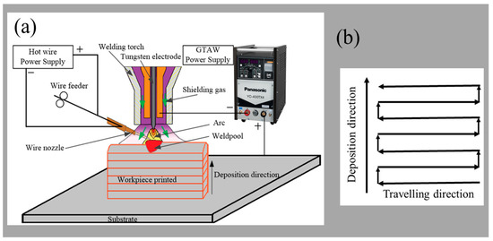
Figure 1.
Schematic diagram of arc additive manufacturing by hot-wire GTAW. (a) The system of the hot-wire GTAW system; (b) a direction schematic of travelling and deposition.
2.2. Material Characterization
The deposited samples were cut along the section direction by a wire metallographic cutter (Laizhou Weiyi Experimental Machinery Manufacture Co., Ltd., Laizhou, China). The metallographic samples were cleaned with acetone in an ultrasonic cleaner (Kunshan Ultrasonic Instrument Co., Ltd., Kunshan, China) to remove surface oil and impurities, ground by sanding with 240#, 600#, 800#, 1200#, and 1500# metallographic sandpaper in turn, and then mechanically polished with 2.5 µm diamond paste. After 30 s in aqua regia solution, the microstructure of the top, middle, and bottom regions of the sample, as shown in Figure 2, was analyzed by a Nikon Epiphot 300 microscope (Nikon Inc., Tokyo, Japan).
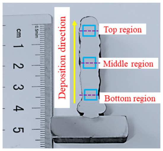
Figure 2.
The positions of the microstructure observation and hardness test.
The hardness tester of the DHV-1000 model (Shanghai Shangcai Tester Machine Co., Ltd., Shanghai, China) was used to test the hardness of the deposited samples. The load was 200 g and the loading time was 10 s. The hardness test was carried out on the top, middle, and bottom regions of the sample, as shown in Figure 2. The distance between each test point was 0.5 mm. Each sample was tested three times, and the average was the final result. Blue boxes were the positions of microstructure observation, and purple dotted lines were the locations of the hardness test, as shown in Figure 2.
Tensile samples were extracted from the bottom, middle, and top areas of the wall component. Test samples a, b, and c were parallel to the traveling direction, and the test sample d was parallel to the deposition direction. Due to the influence of size, the non-standard parts of the tensile samples, as well as the size and the position, are shown in Figure 3. The tensile test was carried out by the Shimadzu electronic universal testing machine AGS-X (Shimadzu (China) Co., Ltd., Beijing, China). The rate was 1 mm/min. To ensure the accuracy of the tensile data, the tensile results for the samples were the average of the five samples. An SU-70 field emission scanning electron microscope (Hitachi, Tokyo, Japan), with an energy-dispersive spectroscope (EDS) (Oxford Instruments, Oxford, England), was employed to observe the fracture morphology of tensile samples, and to study the distribution of elements.
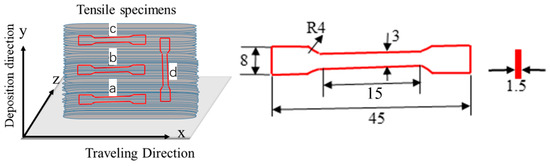
Figure 3.
Schematics of specimen extraction for tensile tests. Samples a, b and c were taken from the x–z plane from top and bottom. Sample d was taken from the x–y plane. R4 means the radius of the arc is 4 mm. The thickness of tensile specimens is 1.5mm. The unit of length in graph is mm.
3. Results Analysis
3.1. Macrostructure
Figure 4 shows the overall macro morphology of the Inconel 625 alloy as-deposited specimen using the hot-wire GTAW process. The substrate had a slight deformation. The component had a surface with a corrugated morphology. The weld bead was compact, and it was free of any cracks and visual defects. The defect-free Inconel 625 alloy was fabricated by WAAM using hot-wire GTAW in this work.
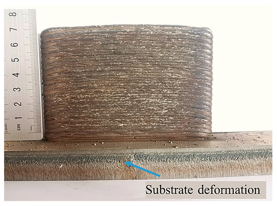
Figure 4.
Macro morphology of Inconel 625 alloy component by hot-wire GTAW.
3.2. Microstructure Observation
Figure 5 shows the microstructure appearance of the Inconel 625 structure in a cross-section from the bottom to the top. There was a noticeable layer band structure along the direction of the deposition height, as shown in Figure 2. Due to the remelting of the interlayer, as shown in Figure 5a, continuity was ensured. Columnar dendrites passed through several deposited layers, which were almost perpendicular to the substrate. Many elongated dendrites appeared near the boundaries between layers, which reflected the good metallurgical bonding. Due to the heat transfer of subsequent layers, the formation of elongated dendrites followed the highest thermal gradient. In the additive manufacturing process, the dendrites of the former deposited layer were remelted by the thermal cycle, and became the nucleation zone of this layer.
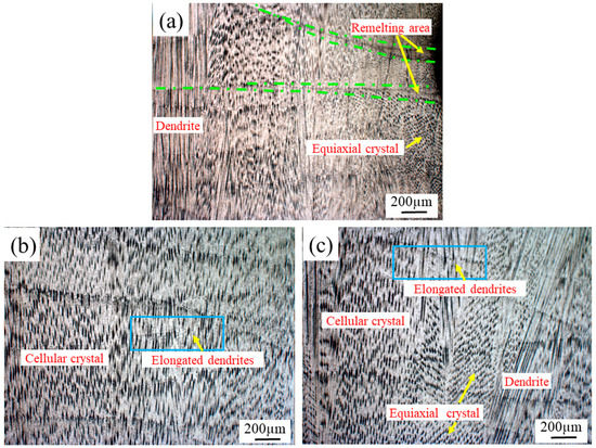
Figure 5.
The section microstructure appearances of the different regions of Inconel 625 alloy: (a) the bottom region; (b) the middle region; (c) the top region.
From the bottom to the top, the microstructure had a different microstructure and grain morphology. At the bottom region, the heat in the molten pool constantly interacted with the surrounding medium. In the initial stage of deposition, the liquid near the substrate was undercooled and solidified, due to the low temperature of the substrate, which led to non-uniform nucleation. After nucleation, the grain continued to grow and form. The growth morphology of the crystal depended on the distribution of the temperature at the front of the interface [23]. The cooling rate was faster, and parts of the solute atoms could not diffuse, thus forming a non-equilibrium solidification structure, namely, dendrite morphology, as shown in Figure 5a. The junction of layers was an arc remelting area, which was mainly related to the arc energy distribution in the deposition process. Near the remelting region, refined equiaxed grains appeared.
In Figure 5b, a fine and uniform dendrite morphology was observed in the middle region. This was because the post-deposition layer played a role in remelting the deposited layer in the continuous multi-layer deposition process. The deposited layer was reheated to a high temperature, resulting in the recrystallization of grains. In the continuous deposition process, a fine and uniform dendritic structure, with a cellular or reticular morphology, was formed because of stable heat input. Therefore, in the middle region, the microstructure presented a typical cellular dendrite morphology.
The microstructure morphology of the top region of the deposited sample is shown in Figure 5c. It has a typical dendritic morphology. The primary dendrite spacing further increased, and the secondary dendrite developed abnormally compared with that in Figure 5a. Between the dendrites, there were cellular crystals and a small number of equiaxial crystals.
According to the above observational results, it was found that the microstructure of the Inconel 625 deposited layer, fabricated by hot-wire arc GTAW, from the bottom to the top, changed from an equiaxial crystal, to cellular crystal, to equiaxial crystal morphology, except for the dendrites. This indicated a certain degree of heterogeneity in the overall structure of the sedimentary layer during continuous deposition. Due to the constant heat input, the accumulation of heat in the deposition process, the gradual decrease in the temperature gradient, and the slow solidification rate, different solidification rates from the bottom to the top were evidenced, and there was inhomogeneity of the overall structure.
3.3. Mechanical Property Analysis
3.3.1. Hardness
The hardness is shown in Figure 6. The hardness curves of different regions, from the bottom to the top, are shown in Figure 6a. There were fluctuations in different regions, reflecting the fact that the hardness in the whole Inconel 625 thin-wall component was not uniform because the microstructure was different. The hardness of the bottom region was higher than those of the top region and the middle region, which was related to the refinement of the bottom region. The average hardness values from the bottom to the top were 214 ± 8 HV, 203 ± 5 HV, and 205 ± 6 HV, in turn. The average hardness values in the bottom, middle and top were very close, indicating good consistency in these three regions.
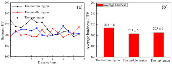
Figure 6.
The hardness and average hardness of the different regions. (a) The hardness curves of defferent regions, (b) The average hardness of the different regions.
3.3.2. Tensile Strength
The room-temperature tensile stress–strain curves and room-temperature mechanical properties of Inconel 625 alloys in different regions are shown in Figure 7 and Figure 8. The elastic deformation of the samples first occurred with the increase in loading force, and plastic deformation occurred when the loading force further increased. With the increase in plastic deformation, the stress of the samples also increased, indicating that the Inconel 625 additively manufactured component had apparent work hardening in the plastic deformation process, until the samples broke and the plastic deformation ended.
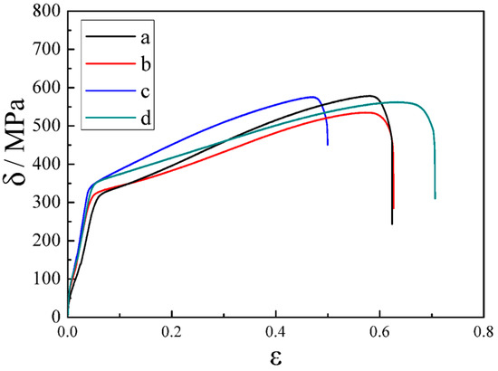
Figure 7.
Stress–strain curves of samples extracted from different positions. Samples a, b and c were taken from the x–z plane from top and bottom. Sample d was taken from the x–y plane, as shown in Figure 3.
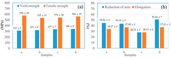
Figure 8.
Tensile properties of samples taken from horizontal (x–y plane) direction. (a,b) A comparison of yield strength and tensile strength, the percentage reduction in area and elongation of samples a, b, c and d.
The values of yield strength, tensile strength, reduction in area, and elongation of the samples, obtained from the stress–strain curves in Figure 7, are shown in Figure 8a,b. The measured yield strength of the samples taken from different parts were 313, 321, 337, and 346 MPa, respectively. The tensile strength of samples a, b, c and d were 578, 535, 574, and 562 MPa, respectively. The tensile strength of the bottom was close to that of the top. The percentage reductions in area were 44.62%, 43.33%, 28.21% and 51.03%, and the percentage elongations were 34.27%, 37.08%, 28.13% and 37.21%, respectively. The greater the elongation and section shrinkage, the better the plasticity of the material. The section shrinkage and elongation indicated that the plasticity in the deposition direction was better. This result was consistent with the results of Brandl, Baufeld and Wang [24,25,26]. This was related to the dendritic structure.
3.3.3. Fracture Behavior Analysis
The fracture positions are shown in Figure 9. There was certain necking in each macro-fracture, which was due to the plastic deformation of the sample in the tensile process, and it also proved that the material produced by additive manufacturing had good plasticity.
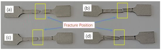
Figure 9.
Fracture position of the tested samples. (a–d) The test samples a, b, c and d, respectively, as shown in Figure 3.
To identify the differences in the tensile performances of the samples, the microstructure of the fracture of the samples was observed by SEM, as shown in Figure 10. Figure 10a–d show the macro-fracture morphologies of samples a, b, c, and d, respectively. Figure 10(a-1, a-2)–(d-1, d-2) show the micro-morphologies of the corresponding fractures, respectively. The macro-fracture morphologies of samples a, b and d are out-of-flatness. In contrast, that of sample c was flat, indicating that the reduction in area rate and the elongation rate of sample c were the lowest among these four samples. This was consistent with the results in Figure 8.
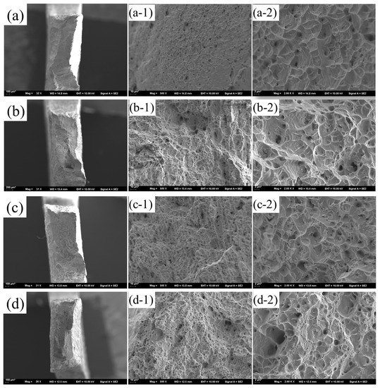
Figure 10.
SEM microstructure of fracture of samples. Figure (a–d) are the macro-fracture morphologies of samples a, b, c, and d, as shown in Figure 3, respectively. Figure (a-1,a-2), (b-1,b-2), (c-1,c-2), and (d-1,d-2) are the micro-morphologies of the test samples a, b, c, and d, respectively.
The fractures of the samples were filled with dimples, indicating that the plasticity of Inconel 625 alloy, fabricated by hot-wire GTAW arc additive manufacturing, was relatively good. The number of micro-pores in the fracture shown in Figure 10b,d was large, which also indicated that the plasticity was relatively good.
The energy spectrum analysis of the second-phase particles of sample d is shown in Figure 11. The result showed that the Al element increased compared with the wire materials, indicating that the second-phase particles were the precipitated phases of Al, and the second-phase particles were almost at the center of the micro-pore, indicating that the second-phase particles aggregated the micro-pores.
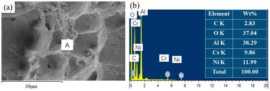
Figure 11.
EDS of point A in the fracture of sample d. Figure (a) is the micro-morphologies of the test sample d, (b) is the EDS of point A in Figure (a).
4. Conclusions
The 625-alloy wire arc additive manufacturing component was successfully fabricated by hot-wire GTAW, and it had good quality, with no defects, such as pores and cracks.
Its microstructure, from the bottom to the top, was changed from an equiaxial crystal, to cellular crystal, to equiaxial crystal morphology, except for the dendrites.
The average hardness of the 625-alloy component, from the bottom to the top, was similar, indicating good consistency. The elongation rate in the deposition direction was better than those in the other three regions. However, the yield strength and tensile strength were smaller, which was related to the dendritic structure in the sedimentary direction. The tensile properties of the horizontal direction were opposite to the results of the elongation rate, and the yield and tensile strength, indicating that the tensile properties of the thin wall, fabricated by additive manufacturing with hot-wire GTAW, had anisotropy.
Certain necking in each macro-fracture was found, and the fractures of the samples were filled with dimples, indicating that the plastic deformation of the sample in the tensile process, and the plasticity of Inconel 625 alloy fabricated by hot-wire GTAW arc additive manufacturing, were relatively good. The microstructure of the fracture of the samples was observed by SEM. The results showed that the precipitated phases of Al aggregated the micro-pores.
Author Contributions
Project administration, X.W.; data curation, Q.H. and T.L.; formal analysis, W.L. and D.T.; investigation, Z.H. and K.L. All authors have read and agreed to the published version of the manuscript.
Funding
The National Science Foundation of China (No. 51675249), the Doctoral Research Fund of Jiangsu University of Science and Technology (No.1062931604) supported this research.
Institutional Review Board Statement
Not applicable.
Informed Consent Statement
Not applicable.
Data Availability Statement
The data used to support the findings of this study are available from the corresponding authors upon request.
Conflicts of Interest
The authors declare no conflict of interest.
References
- Ramkumar, K.D.; Abraham, W.S.; Viyash, V.; Arivazhagan, N.; Rabel, A.M. Investigations on the microstructure, tensile strength and high temperature corrosion behaviour of Inconel 625 and Inconel 718 dissimilar joints. J. Manuf. Process. 2017, 25, 306–322. [Google Scholar] [CrossRef]
- Huebner, J.; Kata, D.; Kusiński, J.; Rutkowski, P.; Lis, J. Microstructure of laser cladded carbide reinforced Inconel 625 alloy for turbine blade application. Ceram. Int. 2017, 43, 8677–8684. [Google Scholar] [CrossRef]
- Li, S.; Wei, Q.; Shi, Y.; Zhu, Z.; Zhang, D. Microstructure characteristics of Inconel 625 superalloy manufactured by selective laser melting. J. Mater. Sci. Technol. 2015, 31, 946–952. [Google Scholar] [CrossRef]
- Xiong, J.; Zhang, G.; Qiu, Z.; Li, Y. Vision-sensing and bead width control of a single-bead multi-layer part: Material and energy savings in GMAW-based rapid manufacturing. J. Clean Prod. 2012, 41, 82–88. [Google Scholar] [CrossRef]
- Colegrove, P.A.; Coules, H.E.; Fairman, J.; Martina, F.; Kashoob, T.; Mamash, H. Microstructure and residual stress improvement in wire and arc additively manufactured parts through high-pressure rolling. J. Mater. Process. Technol. 2013, 213, 1782–1791. [Google Scholar] [CrossRef]
- Basmachi, A.; Erkoyuncu, J.; Colegrover, P.; Martina, F.; Ding, J. Designing a WAAM based manufacturing system for defense applications. Procedia CIRP 2015, 37, 48–53. [Google Scholar]
- Donoghue, J.; Antonysamy, A.A.; Martina, F.; Colegrove, P.A.; Williams, S.W.; Prangnell, P.B. The effectiveness of combining rolling deformation with Wire–Arc Additive Manufacture on β-grain refinement and texture modification in Ti–6Al–4V. Mater. Charact. 2016, 114, 103–114. [Google Scholar] [CrossRef]
- Martina, F.; Mehnen, J.; Williams, S.W.; Colegrove, P.A.; Wang, F. Investigation of the benefits of plasma deposition for the additive layer manufacture of Ti-6Al-4V. J. Mater. Process. Technol. 2012, 212, 1377–1386. [Google Scholar] [CrossRef]
- Geng, H.B.; Li, J.L.; Xiong, J.T.; Lin, X.; Zhang, F.S. Optimization of wire feed for gtaw based additive manufacturing. J. Mater. Process. Technol. 2017, 243, 40–47. [Google Scholar] [CrossRef]
- Li, Y.L.; Zhang, H.; Zhang, G.Y.; Xu, J.N. Precision rapid prototyping of steel parts using TIG depositision technology. Welding 2009, 30, 37–41. [Google Scholar]
- Ouyang, J.H.; Wang, H.; Kovacevic, R. Rapid prototyping of 5356-aluminum alloy based on variable polarity gas tungsten arc welding: Process control and microstructure. Mater. Manuf. Process. 2002, 17, 103–124. [Google Scholar] [CrossRef]
- Hu, Q.X.; Wang, X.L.; Shen, X.W.; Tan, Z.M. Microstructure and corrosion resistance in bimetal materials of Q345 and 308 steel wire-arc additive manufacturing. Crystals 2021, 11, 1401. [Google Scholar] [CrossRef]
- Tabernero, I.; Paskual, A.; Álvarez, P.; Suárez, A. Study on arc welding processes for high deposition rate additive manufacturing. Procedia CIRP 2018, 68, 358–362. [Google Scholar]
- Chen, J.S.; Lu, Y.; Li, X.R.; Zhang, Y.M. Gas Tungsten Arc Welding Using an Arcing wire. Weld. J. 2012, 91, 261–269. [Google Scholar]
- Ueguri, S.; Tabata, Y.; Shimizu, T.; Mizuno, T. A study on control of deposition rate in hot-wire TIG welding. Q. J. J. W. Soc. 1986, 4, 678–684. [Google Scholar] [CrossRef][Green Version]
- Frei, J.; Alexandrov, B.T.; Rethmeier, M. Low heat input gas metal arc welding for dissimilar metal weld overlays part Ⅱ: The transition zone. Weld. World 2018, 62, 317–324. [Google Scholar] [CrossRef]
- Fu, R.; Tang, S.Y.; Lu, J.P.; Cui, Y.N.; Li, Z.X.; Zhang, H.R.; Xu, T.Q.; Chen, Z.; Liu, C.M. Hot-wire arc additive manufacturing of aluminum alloy with reduced porosity and high deposition rate. Mater. Des. 2021, 199, 109370. [Google Scholar] [CrossRef]
- Hu, Q.X.; Miao, J.Y.; Wang, X.L.; Li, C.T.; Fang, K.W. Microstructure and properties of ER50-6 steel fabricated by wire arc additive manufacturing. Scanning 2021, 2021, 7846116. [Google Scholar] [CrossRef] [PubMed]
- Hack, H.; Link, R.; Knudsen, E.; Baker, B.; Olig, S. Mechanical properties of additive manufactured nickel alloy 625. Addit. Manuf. 2017, 14, 105–115. [Google Scholar] [CrossRef]
- Zhao, X.Y.; Dadbakhsh, S.; Rashid, A. Contouring strategies to improve the tensile properties and quality of EBM printed Inconel 625 parts. J. Manuf. Process. 2021, 62, 418–429. [Google Scholar] [CrossRef]
- Li, R.F.; Yuan, W.Y.; Yue, H.Y.; Zhu, Y.Y. Study on microstructure and properties of Fe-based amorphous composite coating by high-speed laser cladding. Opt. Laser Technol. 2022, 146, 107574. [Google Scholar] [CrossRef]
- Luo, S.X.; Li, R.F.; He, P.Y.; Yue, H.Y.; Gu, J.Y. Investigation on the microstructure and mechanical properties of CNTs-AlSi10Mg composites fabricated by selective laser melting. Materials 2021, 14, 838. [Google Scholar] [CrossRef] [PubMed]
- Tao, J.; Yao, Z.J.; Xue, F. Material Science Foundation; Chemical Industry Press: Beijing, China, 2015; pp. 180–191. [Google Scholar]
- Brandl, E.; Baufeld, B.; Leyens, C.; Gault, R. Additive manufactured Ti-6Al-4V using welding wire: Comprision of laser and arc beam deposition and evaluation with respect to aerospace material specifications. Phys. Procedia 2010, 5, 595–606. [Google Scholar] [CrossRef]
- Baufeld, B. Effect of deposition parameters on mechanical properties of shaped metal deposition parts. Proc. Inst. Mech. Eng. Part B J. Eng. Manuf. 2012, 226, 126–136. [Google Scholar] [CrossRef]
- Wang, F.; Williams, S.; Colegrove, P.; Antonysamy, A.A. Microstructure and mechanical properties of wire and arc additive manufactured Ti-6Al-4V. Metal. Mater. Trans. A 2013, 44, 968–977. [Google Scholar] [CrossRef]


Publisher’s Note: MDPI stays neutral with regard to jurisdictional claims in published maps and institutional affiliations. |
© 2022 by the authors. Licensee MDPI, Basel, Switzerland. This article is an open access article distributed under the terms and conditions of the Creative Commons Attribution (CC BY) license (https://creativecommons.org/licenses/by/4.0/).