Article

The Effect of Wall Thickness and Scanning Speed on the Martensitic Transformation and Tensile Properties of Selective Laser Melted NiTi Thin-Wall Structures

1
College of Mechanical and Transportation Engineering, China University of Petroleum, Beijing 102249, China
2
College of New Energy and Materials, China University of Petroleum, Beijing 102249, China
*
Authors to whom correspondence should be addressed.
Metals 2022, 12(3), 519; https://doi.org/10.3390/met12030519
Submission received: 15 January 2022 / Revised: 12 March 2022 / Accepted: 17 March 2022 / Published: 18 March 2022
(This article belongs to the Special Issue Shape Memory Alloys 2022)

Abstract

:
In this study, we analyzed the coupling effect of laser scanning speed and wall thickness on the phase transformation behavior and tensile properties of selective laser melted NiTi thin-wall structures. It is demonstrated that either scanning speed or wall thickness has their respective influence rule, whereas this influence could be changed when coupling them together; that is, under different scanning speeds, the effect of wall thickness could be different. It is found that the deviation of phase transformation temperature among different wall thicknesses is ~3.7 °C at 400 mm/s, while this deviation increases to ~23.5 °C at 600 mm/s. However, the deviation of phase transformation peak width among different wall thicknesses shows little change under different scanning speeds. At low scanning speed, the samples with thicker wall thickness exhibit better tensile ductility than thinner, whereas they all show poor tensile properties and brittle behavior at high scanning speed. This uncertain influence rule is mainly due to the interaction effect between different thermal histories generated by wall thickness and scanning speed.

1. Introduction

NiTi shape memory alloys (SMAs), owing to their unique shape memory effect, superelasticity, excellent corrosion resistance, and biocompatibility, have been used in many applications [1,2,3,4,5], such as actuators, mechanical sensors, orthopedic implants, and cardiac valve scaffolds. However, all conventionally fabricated (smelting and machining) NiTi parts have simple geometries such as wires, plates, bars, tubes, etc. for the poor machinability and weldability [6,7], which critically limits the full applicability of NiTi SMAs. Selective laser melting (SLM) of additive manufacturing is considered a promising method to fabricate the NiTi parts with various complex geometries, due to its high fabricating accuracy and favorable surface smoothness [8,9,10].
For the NiTi parts with complex geometry, feature sizes (e.g., wall thickness, strut diameter) are usually designed to be different to meet the lightweight and performance requirements. According to the specific melting and solidification characteristics of SLM by line-by-line and layer-by-layer manners, it is conceivable that the different feature sizes will induce different thermal histories [11,12] (such as remelting frequency/time, reheating temperature/time, etc.) and cooling conditions [13,14] (cooling direction/rate). For example, compared with the large feature sizes of SLM-fabricated metal parts, the small feature sizes will adopt fewer tracks cumulatively scanning patterns and exhibit higher remelting frequency for small cross-sections, and have a larger temperature gradient of solidification process for the larger specific surface area [15]. Previous studies reported that the different thermal histories caused by feature size would generate differences in element evaporation loss, grain morphology, defects, and precipitates in SLM-NiTi parts [16,17,18]. Thus, the feature size would have a remarkable influence on the phase transformation behavior and mechanical properties of the SLM-NiTi parts with complex geometries [16]. Understanding these evolutions and mechanisms has important practical significance for their structural parts. However, to our knowledge, no attempt has been undertaken so far to clarify the effect of the feature size on the above behaviors of SLM-NiTi parts.
Processing parameter control is the commonly used means of regulating the performances of SLM materials. Laser scanning speed, as one of the key processing parameters, determines directly the energy input density of the molten pool, thus having a significant influence on the temperature and size of the molten pool, element evaporation loss, fluidity, and viscosity of the molten metal and solidification rate [17,19,20]. Previous studies have shown that laser scanning speed profoundly influences the microstructure, metallurgical conditions, and properties of SLM parts [21]. These include the formation of pores, creation of internal stresses, change in alloy composition due to element evaporation, formation of precipitates, and formation of high-density dislocations [22]. From these, the scanning speed is considered as an agitation to feature size effect. However, considering the essential effect of feature size, no study has focused on the coupling effect between scanning speed and feature size on martensitic transformation behavior and mechanical property of SLM-NiTi alloys.
In this study, we analyzed the effect of wall thickness on the martensitic transformation and tensile properties of SLM-NiTi thin-wall structures. Additionally, we also revealed the change in such effect of wall thickness when encountering different scanning speeds. This would contribute to the manufacturing of high-performance SLM-NiTi parts with uneven featured walls or struts.

2. Materials and Methods

The pre-alloyed NiTi powders used for SLM fabrication, with spherical particle sizes ranging from 15 to 53 μm, were obtained by gas atomization from a NiTi bar ingot (Ni: 50.6 at.%). The SLM-NiTi thin-wall structures were fabricated on NiTi substrate by Eplus M100-T SLM machine (e-Plus 3D Tech. Co. Ltd, Beijing, China) under argon protection. The scanning strategy was an orthogonal method and the laser rotates 90° between two layers (as shown in Figure 1a). Four different laser scanning speeds (400 mm/s, 600 mm/s, 800 mm/s and 1000 mm/s) were used for each thin-wall structure. The other processing parameters include laser power of 120 W, hatch spacing of 110 μm, and powder layer thickness of 30 μm. Figure 1b shows the SLM fabricated NiTi thin-wall structures, with the same length of 80 mm and the same height of 10 mm but varied wall thicknesses (t) of 0.4, 0.6, 0.8, 1.2, 2.0, and 4.0 mm.
The microstructure observation was performed on OLYMPUS DSX510 optical microscope (OM) (OLYMPUS Co., Tokyo, Japan). The phase transformation behavior was characterized by differential scanning calorimetry (DSC) (Q20, TA Instruments, New Castle, DE, USA). The samples for DSC were cut from the thin-wall structures at the same location in the center with a weight of 15 mg. The testing temperature range was from −80 °C to 100 °C, with a temperature varying rate of 10 °C/min−1. The lath-shaped samples for the tensile test with the size of 80 × 1 × t (length × height × wall thickness, mm) were cut from the same location of the as-built thin-wall structures by wire-electrode cutting. To ensure the accuracy of the tensile strain values, a tensile test was performed on a material testing system (WDT series, KQL Test Instrument Co. Ltd., Shenzhen, China) equipped with an axial extensometer (Model: 3442-020M-050M-LHT, Epsilon Tec. Cop., Jackson, WY, USA) with a gauge length of 20 mm. The strain rate was always kept as 10−3 s−1. All of the tensile tests were performed 3 times under the same conditions, to ensure the statistical stability of the results.

3. Results and Discussion

Figure 2 shows optical micrographs of the cross-section of SLM-NiTi thin-wall structures fabricated with different scanning speeds. It is seen that high-density keyholes existed inside the samples fabricated with the scanning speed of 400 mm/s, as shown in Figure 2a. This is attributed to the liquid tumbling and vaper ablation under the high energy density of low scanning speed [9,23]. However, the number of keyholes reduced with the improvement in thermal conductivity due to increased thickness. As the scanning speed increased, the pore defects of all samples decreased, and the surface quality gradually decreased with the shortage of energy density, especially for the thin-walled samples. These can also be demonstrated by the porosity evolutions (Figure 3) and the relative densities (Table 1). The relative density of each sample was calculated from the average porosity value of three optical micrographs at the same scale.
Figure 4 shows the etched optical micrographs of thin-wall structures with different thicknesses under scanning speed of 800 mm/s. It is seen that the grains along the build direction changed from large column-like to small vimineous morphology with increased thickness. This is because the thermal conductivity and solidification rate increase as the wall thickness increases during the fabrication process. When the thickness is small enough, the heat of the molten pool dissipates along the horizontal mainly through surrounding loose powders [24,25], of which the thermal conductivity is lower than that of the dense solidified metal [26]. Thus, decreasing the wall thickness of the samples would reduce the solidification rate of the molten pool.
Figure 5 shows the DSC curves of the SLM-NiTi thin-wall structures fabricated with different laser scanning speeds. It is seen that all samples exhibited single-stage B2 → B19′ martensitic transformation upon cooling and single-stage B19′ → B2 reverse martensitic transformation upon heating [17]. More significantly, the phase transformation behavior was affected by both wall thickness and scanning speed.
In Figure 6, the evolutions of martensitic transformation start temperature (Ms) and martensitic transformation peak width (ΔM = MsMf) with scanning speeds and thickness are plotted. It is seen in Figure 6a that all the Ms decreased with the increase in laser scanning speed. This is because the increase in scanning speed reduces the energy input and weakens the Ni element volatilization during the SLM process [27,28]. In addition, the increase in scanning speed shortened the heating time of laser scanning tracks, decreasing the formation of Ni-rich Ni4Ti3 precipitates. Thus, the Ni content of the SLM samples increased with the increase in laser scanning speed. It is also known that Ms highly depends on the matrix solution Ni content in NiTi SMAs, which decreases about 20 °C with the increase of 0.1 at.% Ni [29,30]. As a result, the Ms decreased with the increase in scanning speed.
Figure 6b shows that the effect of wall thickness on Ms was different from the effect of scanning speed. When the scanning speed was 400 mm/s, the Ms were almost stable with wall thickness, where the disparity was only 3.7 °C. When the scanning speed increased to 600 mm/s, 800 mm/s, and 1000 mm/s, the temperature disparity first increased to 23.5 °C and then decreased to 17.5 °C and 11 °C, respectively. Meanwhile, except for the samples fabricated by 400 mm/s, the Ms of all other three samples decreased with the increase in wall thickness. The reasons for this behavior could be explained that the sample with low thickness has low thermal conductivity, as mentioned above. Thus, decreasing the wall thickness of the samples will reduce the solidification rate of the molten pool and thus increase the Ni volatilization. In addition, it is expected that the melting duration and the thermal cycle numbers of peak temperature in the scanning track increase with the decrease in thickness [11], thus increasing the aging time. Therefore, increasing the wall thickness can decrease the Ni volatilization but also hinder the formation of Ni4Ti3 precipitates, thus leading to an increase in the solid solution Ni content and a decrease in Ms.
The reason for the basically unchanged Ms with the thickness in the 400 mm/s samples was found to be that the input of energy density is high enough to give rise to the sufficient Ni volatilization or formation of Ni4Ti3 precipitates, weakening the effect of wall thickness on the Ni content and Ms. With the scanning speed increasing to 600 mm/s, the energy input decreased, and the Ni content increased, which provides potential to change the Ni content and Ms by changing the wall thickness. This caused a remarkable change in Ms with respect to wall thickness. With further increase in the scanning speed, the energy input decreased, and both of the Ni volatilization and formation of Ni-rich precipitates became more insufficient. As a result, the effect of the different wall thicknesses on the change in the solid solution Ni and the temperature disparity of Ms became weaker.
Figure 6c shows that the ΔM obviously increased with the increase in scanning speed, while the temperature deviations of ΔM among different wall thicknesses were kept at ~8 °C at every scanning speed, as shown in Figure 6d. It is known that ΔM is directly affected by the homogeneity of the microstructure of the sample. The inhomogeneity in SLM samples includes the composition segregation induced by Ni nonequilibrium, solidification and the local distribution of Ni-rich precipitates, and the grain size variation between the edge and center of the molten pool [22,31]. With the increase in scanning speed, the laser heat input decreased, inducing a higher solidification rate, thereby more severe composition segregation and larger grain size variation between the edge and the center area of the molten pool [32]. As a result, ΔM at high scanning speed was larger than that of the lower scanning speed. Moreover, the Ni contents in the matrix increased with the increase in scanning speed, promoting Ni4Ti3 precipitates; therefore, it was not conducive to the homogeneity of the microstructure. Thus, ΔM of all samples with different wall thicknesses increased with the increase in scanning speed. In addition, decreasing the thickness would reduce the solidification rate and then reduce the ΔM. However, Figure 6d indicates that the effect of the thickness on the microstructural non-uniformity was far less than that of the scanning speed.
Figure 7 shows the tensile stress–strain curves of the thin-wall structures fabricated with different scanning speeds at ambient temperature (~20 °C). According to the DSC results in Figure 5, the samples were dominated by B2 austenite phase state at 20 °C. Hence, it was speculated that they mainly experience stress-induced martensite transformation (SIMT) upon tensile loading. Figure 8 shows the evolution of fracture strain of all samples with the wall thickness under different scanning speeds, which is based on mathematical statistics of repeated experiments in Figure 7. It is seen that the samples fabricated at 400 mm/s all exhibited excellent tensile ductility (>8%), and their fracture strains basically increased with the increased wall thickness.
It is widely reported that pore defects always exist in SLM-fabricated metal parts, and they are believed to deteriorate the fracture strain due to the stress concentrations at the pore edges [33,34]. The stress concentration will easily trigger the nucleation and propagation of dislocations and cracks. It is well reported that the SIMT process in NiTi alloys can release the stress concentration at the pore edges by the ~8% SIMT strain [35,36], and the strain strengthening of the stress-induced martensite can further hinder the plastic deformation [37]. Thus, the SIMT process tends to suspend the crack nucleation and propagation in front of pore edges and then increases the fracture strain and improves the ductility of NiTi alloys. It is well known that the critical stress for SIMT highly depends on the temperature disparity between Ms and testing temperature [38]). Specifically, the temperature disparity increased by 1 °C, while the critical stress of SIMT increased by 6–7 MPa [39,40]. When the scanning speed was 400 mm/s, the samples had the highest Ms, which approached the ambient temperature for the tensile test (Figure 2a). Their critical stresses for SIMT were the lowest, which made the samples easily undergo SIMT and then exhibit the best ductility. Thus, this made the stress–strain curves for 400 mm/s specimens very different from others and exhibited secondary hardening stage alone. At ~150 MPa, as shown in Figure 7a, the specimens started to undergo uniform shear deformation by stress-induced martensitic transformation (horizontal stress stage). After the transformation was completed, transformed martensite had strong work hardening ability, and the slope of stress–strain curves rose again (curves upward again). As the wall thickness increased, the porosity decreased (Figure 3b), and then fracture strain increased.
As seen in Figure 8, the evolutions of fracture strain of specimens with their wall thickness undergoing other scanning speeds are obviously different from that of 400 mm/s. With the increase in scanning speed, the tensile ductility deteriorated rapidly, i.e., the fracture strains of the samples fabricated with 1000 mm/s were mostly less than 6%. Meanwhile, the SIMT critical stress increased dramatically, from ~150 MPa to ~400 MPa, close to the yield stress with the scanning speed increasing from 400 mm/s to 1000 mm/s, as shown in Figure 7. This indicates that the poor plasticity of these samples may be due to the increase in SIMT critical stress and decrease in surface quality. Thus, the improvement of porosity was no longer the main controlling factor. With the wall thickness increasing, the Ms further decreased and critical stress for stress-induced transformation further improved; thus, the specimens were accompanied by increasing levels of irreversible dislocation slip deformation in the process of stress-induced transformation, sequentially reducing the fracture strain. Similarly, the stress–strain curves had not yet exhibited secondary work hardening ability as had that of 400 mm/s.
With the increase in scanning speed, the Ms decreased, as shown in Figure 5. Thus, the critical stress for SIMT increased with the increase in the temperature disparity between Ms and testing temperature. The transformation peak width (ΔM) also significantly increased with the increase in scanning speed, indicating that the inhibition of complete SIMT gradually increased. Furthermore, the grain sizes of the SLM-fabricated NiTi samples are larger than tens of microns, which results in low critical stress for plastic deformation [27,41,42]. Therefore, although the samples fabricated with high scanning speeds had few pore defects, plastic deformation would easily occur in such samples at the surface defect instead of SIMT, after which they would become brittle. To further indicate the superior pore tolerance under the martensitic state, the tensile tests of samples fabricated with 800 mm/s were carried out at 10 °C below the martensitic transformation finish temperature (Mf). As shown in Figure 9, it was found that the fracture strains of each sample increased by >3%, when they were tested in a fully martensitic state.

4. Conclusions

(1)
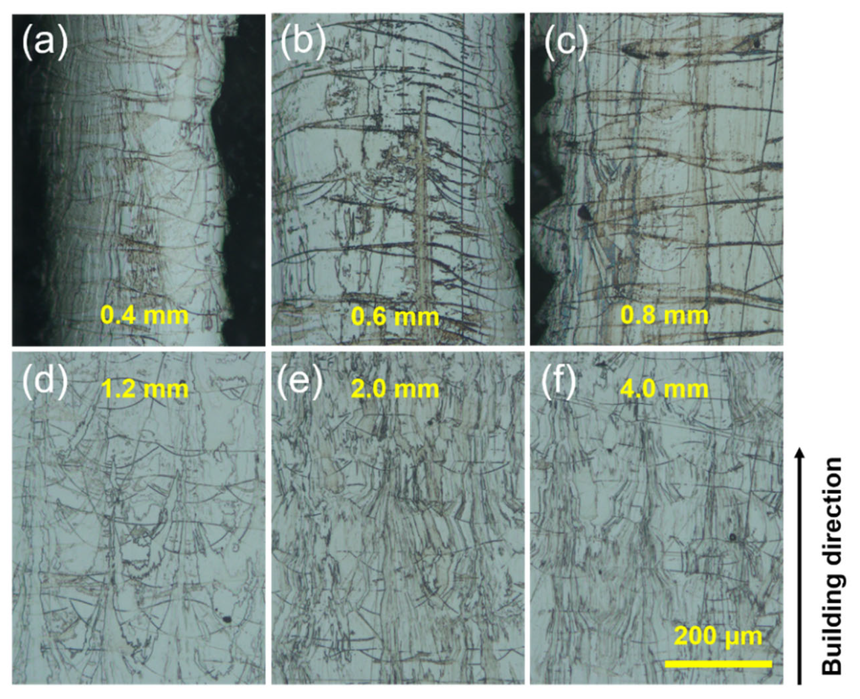
As the scanning speed increased, the porosity decreased, and the surface quality decreased. As the wall thickness increased, the thermal conductivity efficiency and solidification rate increased, resulting in grain refinement.
(2)
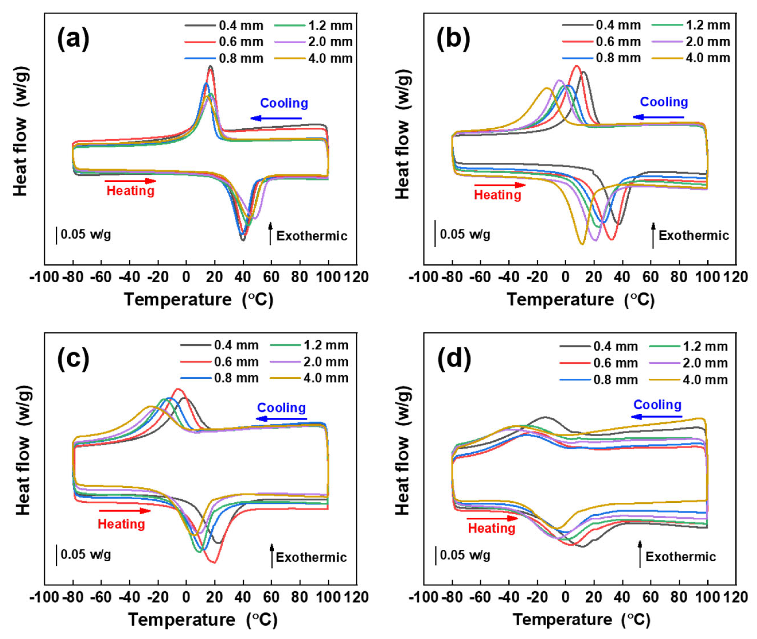
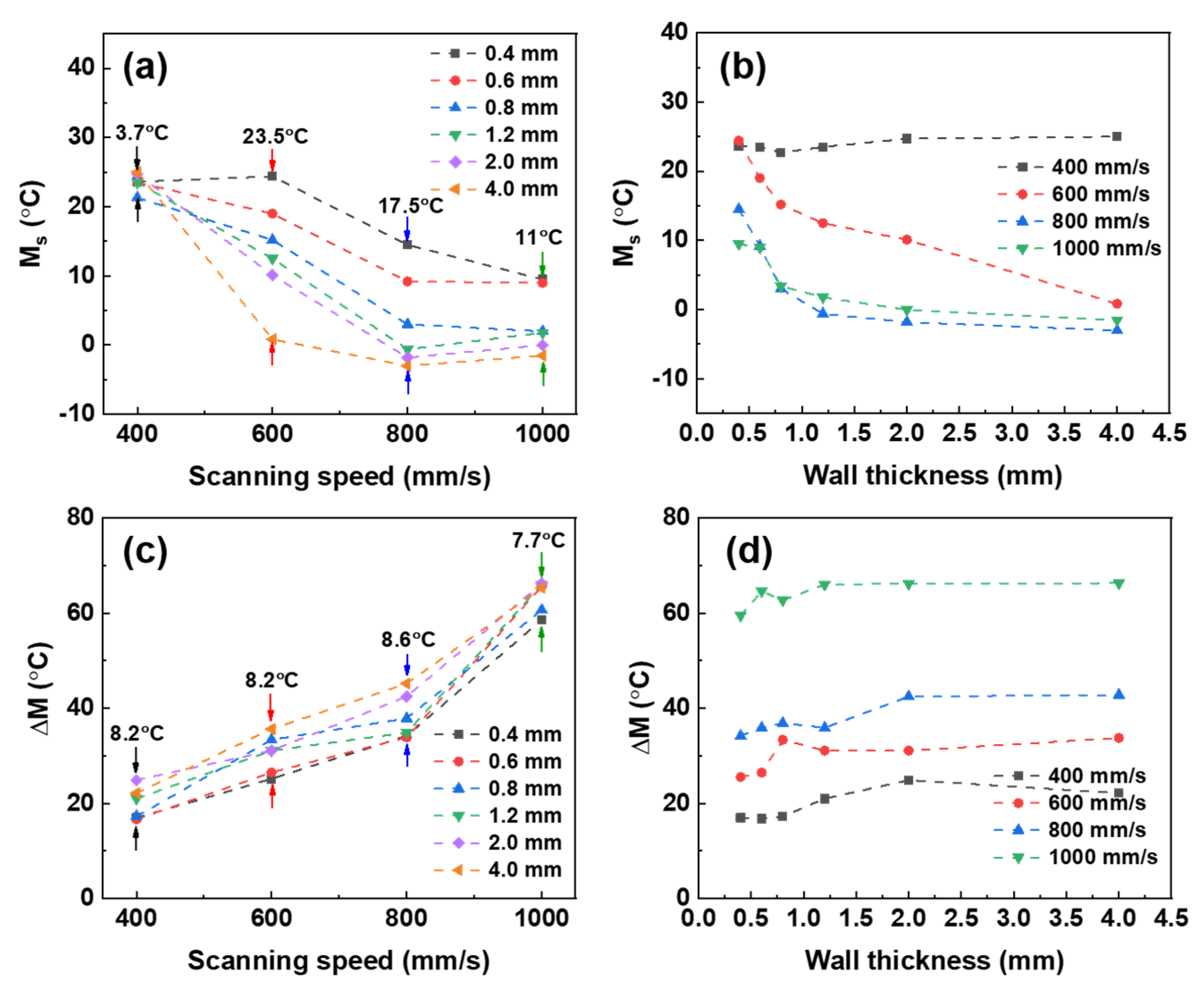
The effect of wall thickness on martensite transformation was revealed. The deviations of Ms among different wall thicknesses were small at 400 mm/s but became much larger with increasing scanning speed, whereas the deviation of ΔM among different wall thicknesses showed little change. In complex NiTi structures, the transformation temperatures caused by feature size change at different positions need to be considered.
(3)
The effect of wall thickness on Ms and ΔM had various situations, and it was different at different scanning speeds. This indicates that feature size effects of phase transformation can be regulated by processing parameters (scanning speed), which is referential in the process design of structural parts.
(4)
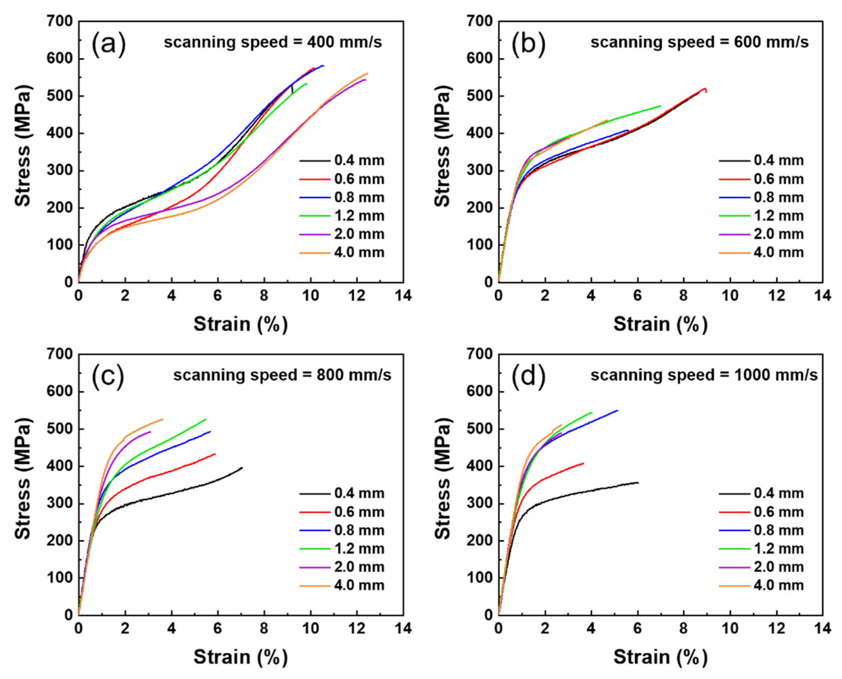
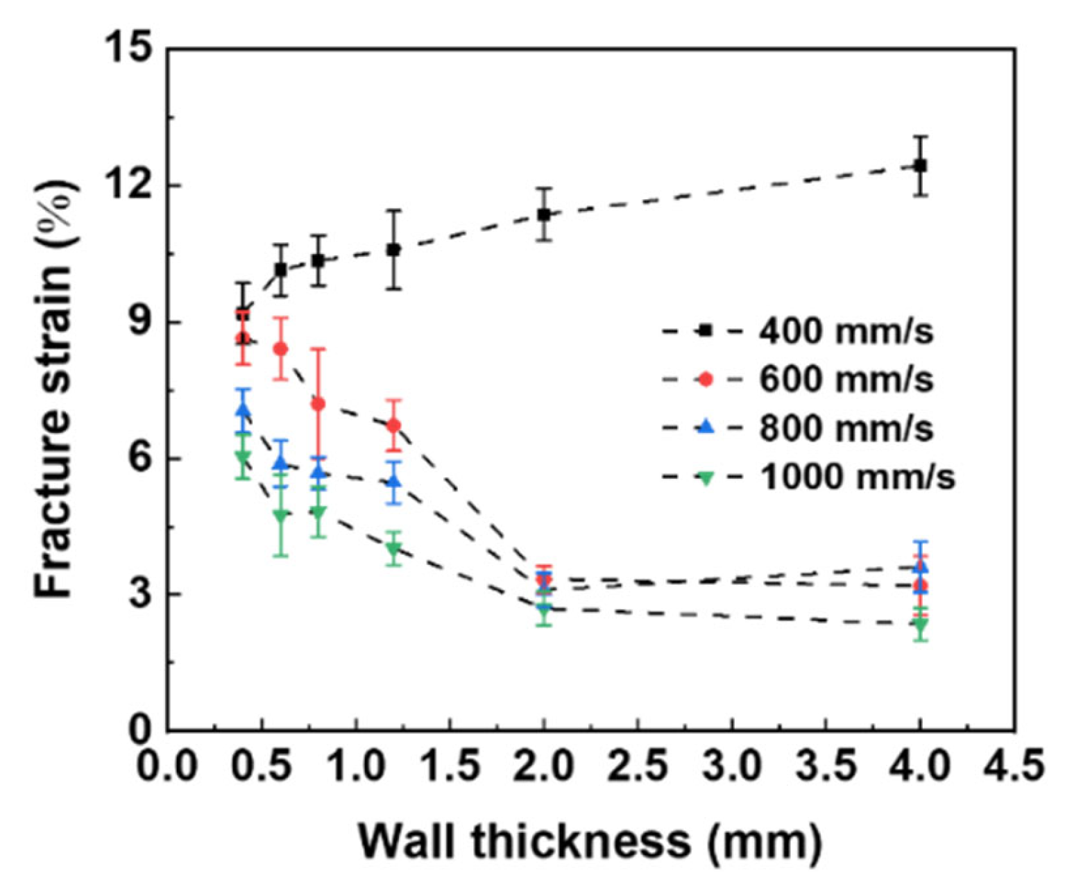
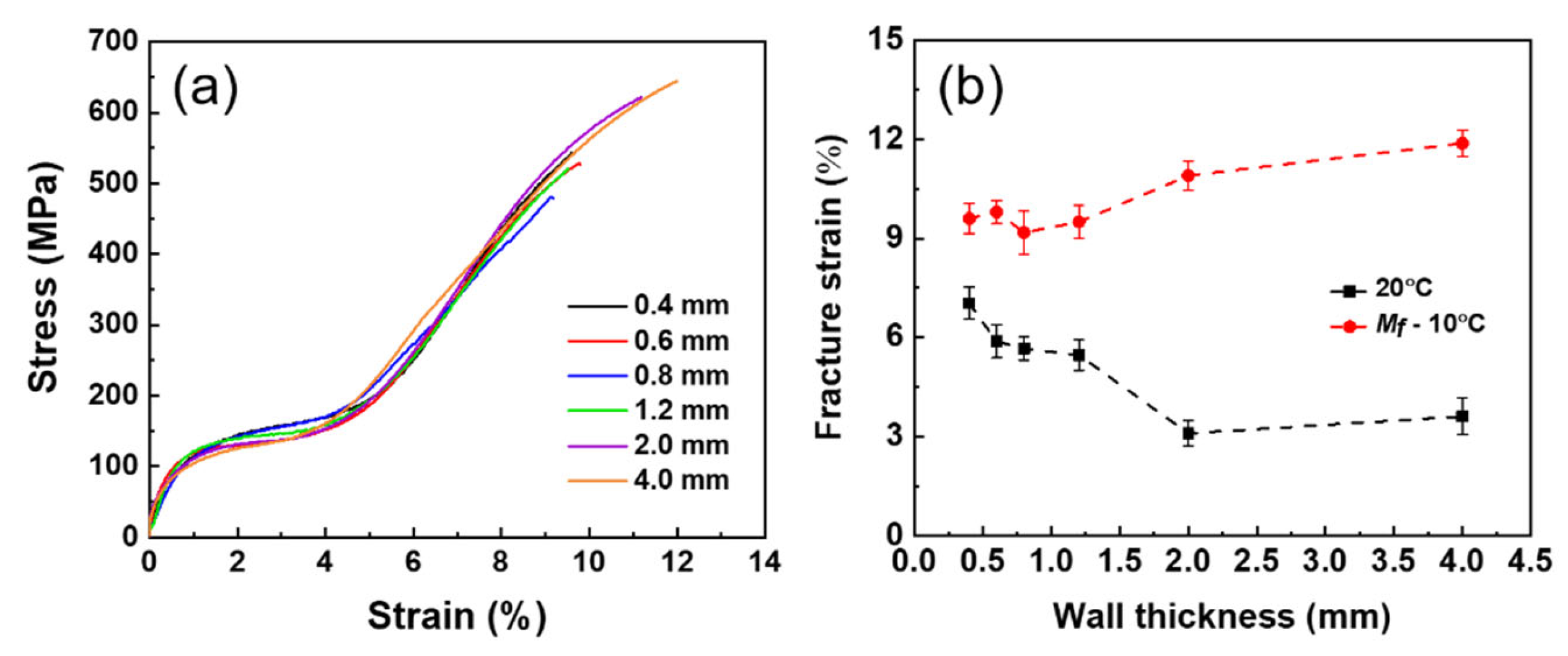
Under the scanning speed of 400 mm/s, the samples with thicker wall thickness exhibited better tensile ductility than thinner, which may be attributed to their low critical stress for SIMT. The low critical stress for SIMT can easily suppress the stress concentration caused by pore defects during loading. This also embodied the sample under martensitic state, which showed superior ductility, compared with austenite state. On the other hand, the samples fabricated using high scanning speed all showed poor tensile properties and brittle behavior due to their high critical stress for SIMT and poor surface quality.

Author Contributions

Conceptualization, F.G. and S.H.; methodology, F.G.; formal analysis and investigation, F.G. and Y.G.; writing—original draft preparation, F.G.; writing—review and editing, S.H., Z.X. and X.K.; project administration, Y.G.; funding acquisition, S.H. All authors have read and agreed to the published version of the manuscript.

Funding

This research was funded by the Joint Fund of National Natural Science Foundation Committee and Chinese Academy of Engineering Physics (NSAF) (No. U2130201), the Natural Science Foundation of China (No. 51971244 and No. 51731010), and the Advanced Structural Technology Foundation of China (No. 2020-JCJQ-JJ-024).

Data Availability Statement

Not applicable.

Conflicts of Interest

The authors declare no conflict of interest.

References

  1. Mohd Jani, J.; Leary, M.; Subic, A.; Gibson, M.A. A review of shape memory alloy research, applications and opportunities. Mater. Des. 2014, 56, 1078–1113. [Google Scholar] [CrossRef]
  2. Hang, R.; Zhao, F.; Yao, X.; Tang, B.; Chu, P.K. Self-assembled anodization of NiTi alloys for biomedical applications. Appl. Surf. Sci. 2020, 517, 146118. [Google Scholar] [CrossRef]
  3. Machado, L.G.; Savi, M.A. Medical applications of shape memory alloys. Braz. J. Med. Biol. Res. 2003, 36, 683–691. [Google Scholar] [CrossRef] [PubMed]
  4. Sun, L.; Huang, W.M.; Ding, Z.; Zhao, Y.; Wang, C.C.; Purnawali, H.; Tang, C. Stimulus-responsive shape memory materials: A review. Mater. Des. 2012, 33, 577–640. [Google Scholar] [CrossRef]
  5. Patel, S.K.; Behera, B.; Swain, B.; Roshan, R.; Sahoo, D.; Behera, A. A review on NiTi alloys for biomedical applications and their biocompatibility. Mater. Today Proc. 2020, 33, 5548–5551. [Google Scholar] [CrossRef]
  6. Mwangi, J.W.; Nguyen, L.T.; Bui, V.D.; Berger, T.; Zeidler, H.; Schubert, A. Nitinol manufacturing and micromachining: A review of processes and their suitability in processing medical-grade nitinol. J. Manuf. Processes 2019, 38, 355–369. [Google Scholar] [CrossRef]
  7. Xiong, Z.; Li, Z.; Sun, Z.; Hao, S.; Yang, Y.; Li, M.; Song, C.; Qiu, P.; Cui, L. Selective laser melting of NiTi alloy with superior tensile property and shape memory effect. J. Mater. Sci. Technol. 2019, 35, 2238–2242. [Google Scholar] [CrossRef]
  8. Dadbakhsh, S.; Vrancken, B.; Kruth, J.P.; Luyten, J.; Van Humbeeck, J. Texture and anisotropy in selective laser melting of NiTi alloy. Mater. Sci. Eng. A 2016, 650, 225–232. [Google Scholar] [CrossRef]
  9. Seede, R.; Shoukr, D.; Zhang, B.; Whitt, A.; Gibbons, S.; Flater, P.; Elwany, A.; Arroyave, R.; Karaman, I. An ultra-high strength martensitic steel fabricated using selective laser melting additive manufacturing: Densification, microstructure, and mechanical properties. Acta Mater. 2020, 186, 199–214. [Google Scholar] [CrossRef]
  10. De Wild, M.; Meier, F.; Bormann, T.; Howald, C.B.C.; Müller, B. Damping of selective-laser-melted NiTi for medical implants. J. Mater. Eng. Perform. 2014, 23, 2614–2619. [Google Scholar] [CrossRef] [Green Version]
  11. Li, Z.; Xu, R.; Zhang, Z.; Kucukkoc, I. The influence of scan length on fabricating thin-walled components in selective laser melting. Int. J. Mach. Tools Manuf. 2018, 126, 1–12. [Google Scholar] [CrossRef]
  12. Majeed, A.; Ahmed, A.; Liu, B.; Ren, S.; Yang, J. Influence of wall thickness on the hardness of AlSi10Mg alloy parts manufactured by selective laser melting. Procedia CIRP 2019, 81, 459–463. [Google Scholar] [CrossRef]
  13. Dzugan, J.; Seifi, M.; Prochazka, R.; Rund, M.; Podany, P.; Konopik, P.; Lewandowski, J.J. Effects of thickness and orientation on the small scale fracture behaviour of additively manufactured Ti-6Al-4V. Mater. Charact. 2018, 143, 94–109. [Google Scholar] [CrossRef]
  14. Algardh, J.K.; Horn, T.; West, H.; Aman, R.; Snis, A.; Engqvist, H.; Lausmaa, J.; Harrysson, O. Thickness dependency of mechanical properties for thin-walled titanium parts manufactured by Electron Beam Melting (EBM)®. Addit. Manuf. 2016, 12, 45–50. [Google Scholar] [CrossRef]
  15. Barba, D.; Alabort, C.; Tang, Y.T.; Viscasillas, M.J.; Reed, R.C.; Alabort, E. On the size and orientation effect in additive manufactured Ti-6Al-4V. Mater. Des. 2020, 186, 108235. [Google Scholar] [CrossRef]
  16. Farjam, N.; Nematollahi, M.; Andani, M.T.; Mahtabi, M.J.; Elahinia, M. Effects of size and geometry on the thermomechanical properties of additively manufactured NiTi shape memory alloy. Int. J. Adv. Manuf. Technol. 2020, 107, 3145–3154. [Google Scholar] [CrossRef]
  17. Wang, X.; Yu, J.; Liu, J.; Chen, L.; Yang, Q.; Wei, H.; Sun, J.; Wang, Z.; Zhang, Z.; Zhao, G.; et al. Effect of process parameters on the phase transformation behavior and tensile properties of NiTi shape memory alloys fabricated by selective laser melting. Addit. Manuf. 2020, 36, 101545. [Google Scholar] [CrossRef]
  18. Dadbakhsh, S.; Speirs, M.; Kruth, J.P.; Schrooten, J.; Luyten, J.; Van Humbeeck, J. Effect of SLM parameters on transformation temperatures of shape memory nickel titanium parts. Adv. Eng. Mater. 2014, 16, 1140–1146. [Google Scholar] [CrossRef]
  19. Miranda, G.; Faria, S.; Bartolomeu, F.; Pinto, E.; Alves, N.; Peixinho, N.; Gasik, M.; Silva, F.S. A study on the production of thin-walled Ti6Al4V parts by selective laser melting. J. Manuf. Processes 2019, 39, 346–355. [Google Scholar] [CrossRef]
  20. Zhou, Y.; Chen, S.; Chen, X.; Liang, J.; Liu, C.; Wang, M. The effect of laser scanning speed on microstructural evolution during direct laser deposition 12CrNi2 alloy steel. Opt. Laser Technol. 2020, 125, 106041. [Google Scholar] [CrossRef]
  21. Mahmoudi, M.; Tapia, G.; Franco, B.; Ma, J.; Arroyave, R.; Karaman, I.; Elwany, A. On the printability and transformation behavior of nickel-titanium shape memory alloys fabricated using laser powder-bed fusion additive manufacturing. J. Manuf. Processes 2018, 35, 672–680. [Google Scholar] [CrossRef]
  22. Zhang, Q.; Hao, S.; Liu, Y.; Xiong, Z.; Guo, W.; Yang, Y.; Ren, Y.; Cui, L.; Ren, L.; Zhang, Z. The microstructure of a selective laser melting (SLM)-fabricated NiTi shape memory alloy with superior tensile property and shape memory recoverability. Appl. Mater. Today 2020, 19, 100547. [Google Scholar] [CrossRef]
  23. Khairallah, S.A.; Anderson, A.T.; Rubenchik, A.; King, W.E. Laser powder-bed fusion additive manufacturing: Physics of complex melt flow and formation mechanisms of pores, spatter, and denudation zones. Acta Mater. 2016, 108, 36–45. [Google Scholar] [CrossRef] [Green Version]
  24. Yang, J.; Yang, H.; Yu, H.; Wang, Z.; Wang, H.; Zeng, X. A novel approach to in-situ fabricate Ti-6Al-4V alloy with graded microstructure and property by selective laser melting. Mater. Lett. 2018, 215, 246–249. [Google Scholar] [CrossRef]
  25. Antonysamy, A.A.; Meyer, J.; Prangnell, P.B. Effect of build geometry on the β-grain structure and texture in additive manufacture of Ti6Al4V by selective electron beam melting. Mater. Charact. 2013, 84, 153–168. [Google Scholar] [CrossRef]
  26. Lin, K.; Yuan, L.; Gu, D. Influence of laser parameters and complex structural features on the bio-inspired complex thin-wall structures fabricated by selective laser melting. J. Mater. Process. Technol. 2019, 267, 34–43. [Google Scholar] [CrossRef]
  27. Elahinia, M.; Shayesteh Moghaddam, N.; Taheri Andani, M.; Amerinatanzi, A.; Bimber, B.A.; Hamilton, R.F. Fabrication of NiTi through additive manufacturing: A Review. Prog. Mater. Sci. 2016, 83, 630–663. [Google Scholar] [CrossRef] [Green Version]
  28. Speirs, M.; Wang, X.; Van Baelen, S.; Ahadi, A.; Dadbakhsh, S.; Kruth, J.P.; Van Humbeeck, J. On the Transformation Behavior of NiTi Shape-Memory Alloy Produced by SLM. Shape Mem. Shape Mem. Superelast. 2016, 2, 310–316. [Google Scholar] [CrossRef] [Green Version]
  29. Otsuka, K.; Ren, X. Physical metallurgy of Ti-Ni-based shape memory alloys. Prog. Mater. Sci. 2005, 50, 511–678. [Google Scholar] [CrossRef]
  30. Frenzel, J.; George, E.P.; Dlouhy, A.; Somsen, C.; Wagner, M.F.X.; Eggeler, G. Influence of Ni on martensitic phase transformations in NiTi shape memory alloys. Acta Mater. 2010, 58, 3444–3458. [Google Scholar] [CrossRef]
  31. Gu, D.; Ma, C. In-situ formation of Ni4Ti3 precipitate and its effect on pseudoelasticity in selective laser melting additive manufactured NiTi-based composites. Appl. Surf. Sci. 2018, 441, 862–870. [Google Scholar] [CrossRef]
  32. Guo, W.; Feng, B.; Yang, Y.; Ren, Y.; Liu, Y.; Yang, H.; Yang, Q.; Cui, L.; Tong, X.; Hao, S. Materials & Design Effect of laser scanning speed on the microstructure, phase transformation and mechanical property of NiTi alloys fabricated by LPBF. Mater. Des. 2022, 215, 110460. [Google Scholar] [CrossRef]
  33. Wang, D.; Song, C.; Yang, Y.; Bai, Y. Investigation of crystal growth mechanism during selective laser melting and mechanical property characterization of 316L stainless steel parts. Mater. Des. 2016, 100, 291–299. [Google Scholar] [CrossRef]
  34. Zhao, C.; Bai, Y.; Zhang, Y.; Wang, X.; Xue, J.M.; Wang, H. Influence of scanning strategy and building direction on microstructure and corrosion behaviour of selective laser melted 316L stainless steel. Mater. Des. 2021, 209, 109999. [Google Scholar] [CrossRef]
  35. Wang, G.Z. Effect of martensite transformation on fracture behavior of shape memory alloy NiTi in a notched specimen. Int. J. Fract. 2007, 146, 93–104. [Google Scholar] [CrossRef]
  36. Chen, J.H.; Sun, W.; Wang, G.Z. Investigation on the fracture behavior of shape memory alloy NiTi. Metall. Mater. Trans. A Phys. Metall. Mater. Sci. 2005, 36, 941–955. [Google Scholar] [CrossRef]
  37. Zhang, J.; Hao, S.; Jiang, D.; Huan, Y.; Cui, L.; Liu, Y.; Yang, H.; Ren, Y. In situ synchrotron high-energy X-ray diffraction study of microscopic deformation behavior of a hard-soft dual phase composite containing phase transforming matrix. Acta Mater. 2017, 130, 297–309. [Google Scholar] [CrossRef] [Green Version]
  38. Omori, T.; Ando, K.; Okano, M.; Xu, X.; Tanaka, Y.; Ohnuma, I.; Kainuma, R.; Ishida, K. Superelastic effect in polycrystalline ferrous alloys. Science 2011, 333, 68–71. [Google Scholar] [CrossRef]
  39. Wang, T.; Ma, Z.; Rao, X.; Jiang, D.; Ren, Y.; Liu, Y.; Yu, K.Y.; Cui, L. Temperature-dependence of superelastic stress in nanocrystalline NiTi with complete transformation capability. Intermetallics 2020, 127, 106970. [Google Scholar] [CrossRef]
  40. Miyazaki, S. My Experience with Ti–Ni-Based and Ti-Based Shape Memory Alloys. Shape Mem. Superelast. 2017, 3, 279–314. [Google Scholar] [CrossRef]
  41. Khoo, Z.X.; Liu, Y.; An, J.; Chua, C.K.; Shen, Y.F.; Kuo, C.N. A review of selective laser melted NiTi shape memory alloy. Materials 2018, 11, 519. [Google Scholar] [CrossRef] [PubMed] [Green Version]
  42. Dadbakhsh, S.; Speirs, M.; Kruth, J.P.; Van Humbeeck, J. Influence of SLM on shape memory and compression behaviour of NiTi scaffolds. CIRP Ann.-Manuf. Technol. 2015, 64, 209–212. [Google Scholar] [CrossRef] [Green Version]
Figure 1. (a) Illustration of the orthogonal-type laser scanning strategy; (b) the NiTi plate samples were fabricated by SLM.
Metals 12 00519 g001
Figure 2. Optical micrographs of SLM-NiTi thin-wall structures fabricated by different laser scanning speeds: (a) 400 mm/s, (b) 600 mm/s, (c) 800 mm/s, and (d) 1000 mm/s.
Metals 12 00519 g002
Figure 3. The evolutions of porosity with (a) scanning speed and (b) wall thickness.
Metals 12 00519 g003
Figure 4. Optical micrographs of thin-wall structures along the build direction with different thickness under scanning speed of 800 mm/s: (a) 0.4 mm, (b) 0.6 mm, (c) 0.8 mm, (d) 1.2 mm, (e) 2.0 mm, and (f) 4.0 mm.
Metals 12 00519 g004
Figure 5. The DSC curves of SLM-NiTi thin-wall structures fabricated with different laser scanning speeds: (a) 400 mm/s, (b) 600 mm/s, (c) 800 mm/s, and (d) 1000 mm/s.
Metals 12 00519 g005
Figure 6. The martensitic transformation starting temperature (Ms) and martensitic transformation peak width (ΔM = MsMf) of SLM-NiTi thin-wall structures as a function of wall thickness and laser scanning speed: (a) evolution of Ms with scanning speed; (b) evolution of ΔM with scanning speed; (c) evolution of Ms with wall thickness; (d) evolution of ΔM with wall thickness.
Metals 12 00519 g006
Figure 7. The stress–strain curves of the samples fabricated at different scanning speeds: (a) 400 mm/s, (b) 600 mm/s, (c) 800 mm/s, and (d) 1000 mm/s.
Metals 12 00519 g007
Figure 8. The evolution of fracture strain of all samples in Figure 7 with wall thickness under different scanning speeds (the error bars are derived from repeated experiments under the same conditions).
Metals 12 00519 g008
Figure 9. (a) The tensile stress–strain curves of the samples fabricated with 800 mm/s tested at 10 °C below the martensite transformation finish temperature (Mf), corresponding test temperatures were −30, −15, −45, −46, −54, and −58 °C as the wall thickness increased, respectively; (b) the comparison of the fracture strain and fracture stress tested at 20 °C and Mf − 10 °C corresponding to (a) (the error bars are derived from repeated experiments under the same conditions).
Metals 12 00519 g009
Table 1. The relative density of samples with different wall thickness and scanning speeds.
Wall ThicknessRelative Density
400 mm/s600 mm/s800 mm/s1000 mm/s
0.4 mm94.39%99.79%99.81%99.71%
0.6 mm95.27%99.91%99.89%99.93%
0.8 mm95.46%99.87%99.97%99.96%
1.2 mm98.50%99.95%99.96%99.94%
2.0 mm99.97%99.98%99.97%99.96%
4.0 mm99.61%99.96%99.98%99.99%
Publisher’s Note: MDPI stays neutral with regard to jurisdictional claims in published maps and institutional affiliations.

