
Investigation of Applicability Flowdrill Technology for Joining Thin-Walled Metal Sheets

 ,
,  , , ,
, , ,
Abstract
:1. Introduction
2. Materials and Methods
2.1. Materials of Workpieces
- Cold rolled uncoated deep drawing steel DC04, used for the production of interior and exterior parts of car bodies and for other stampings.
- Zinc-galvanized fine-grained high-strength microalloyed steel TL 1550-220+Z with increased cold formability.
- Precipitation hardened aluminum alloy EN AW-6082 T6 (AlSi1MgMn).
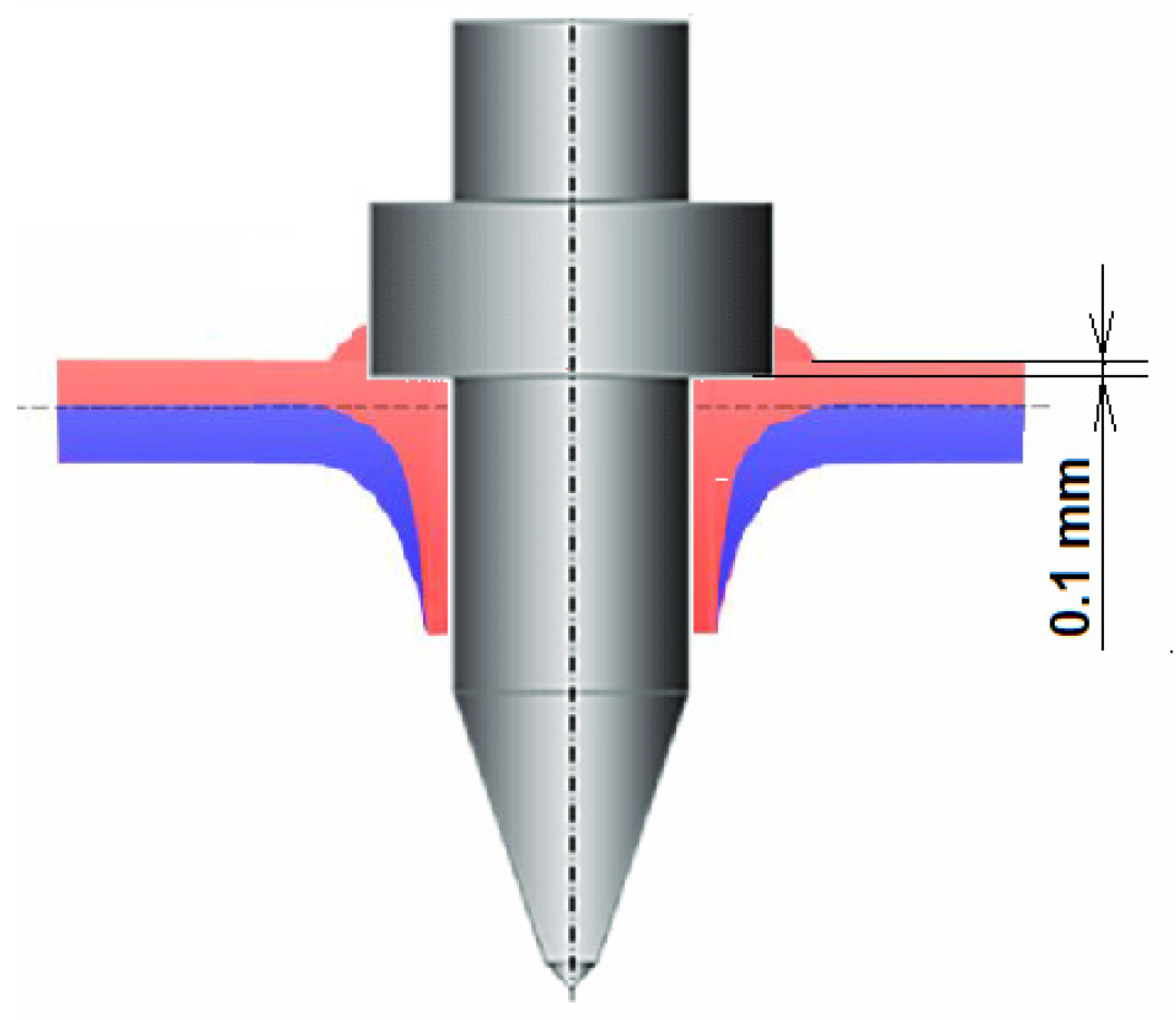
2.2. Flowdrill Tool, Parameters of the Drilling Process
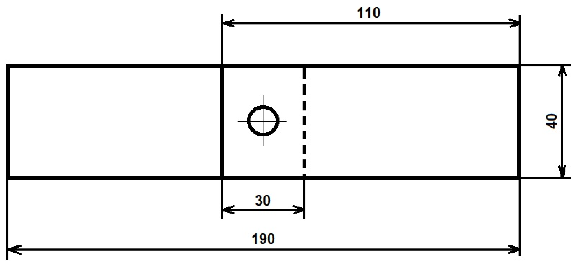
2.3. Shape and Dimensions of Test Specimens
2.4. Adhesive and Adhesive Bonding Process
2.5. Testing of Joint Assemblies
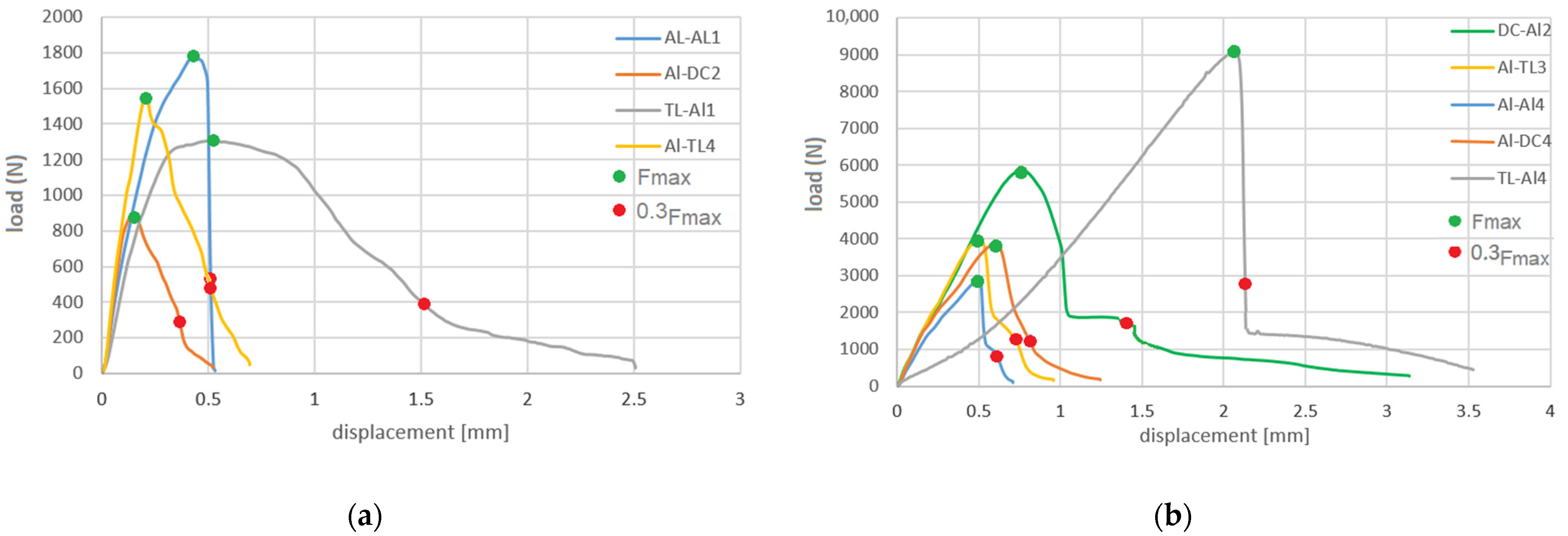
- Fmax—tensile shear force, the maximum force recorded during the test.
- sFmax—displacement at the tensile shear force Fmax.
- 0.3Fmax—tensile shear force on the downward part of the curve corresponding to 30% of Fmax.
- s0.3Fmax—displacement at 0.3Fmax.
3. Results
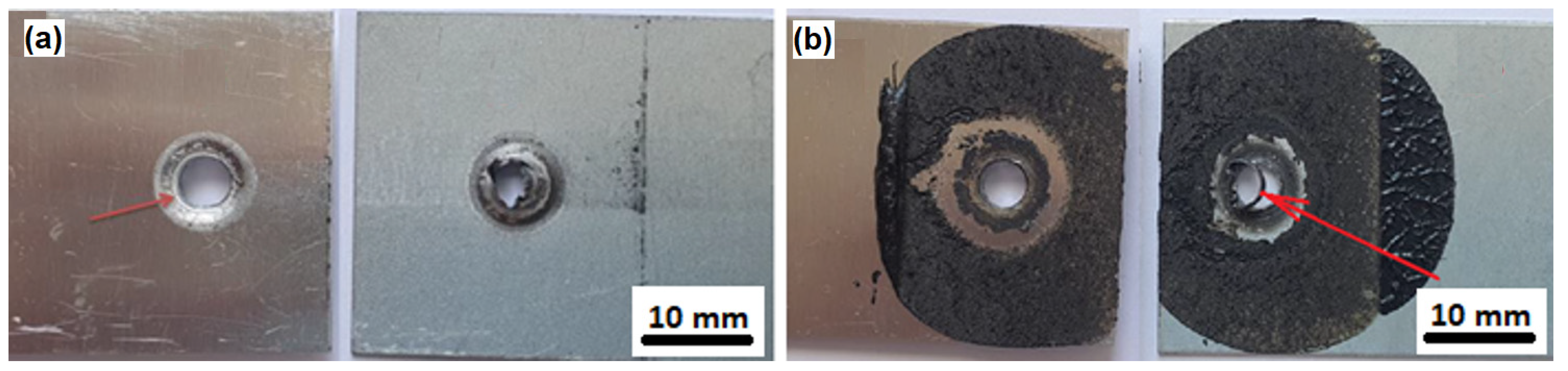
3.1. Visual Assessment of Joints
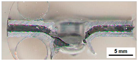
3.2. Macroscopic Evaluation of Joints
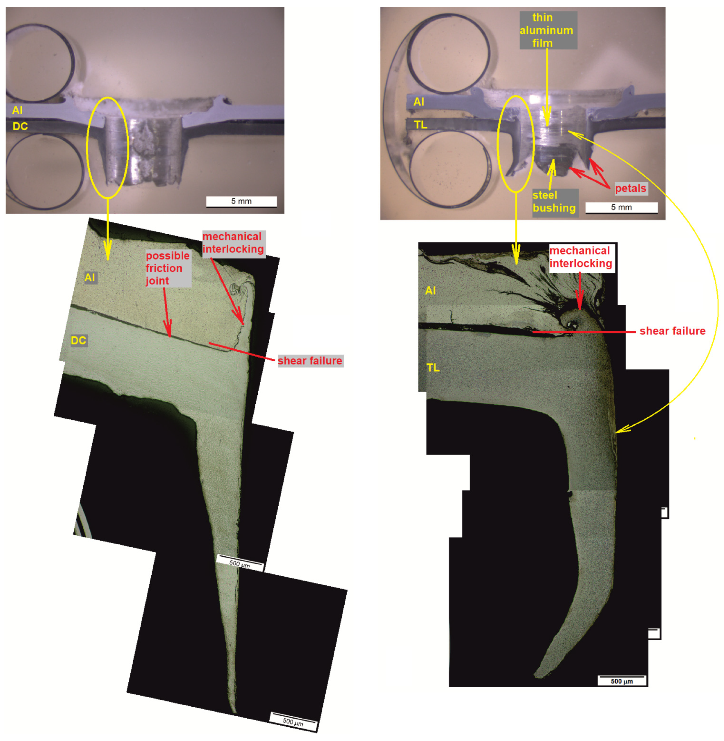
3.3. Microscopic Evaluation of Joints
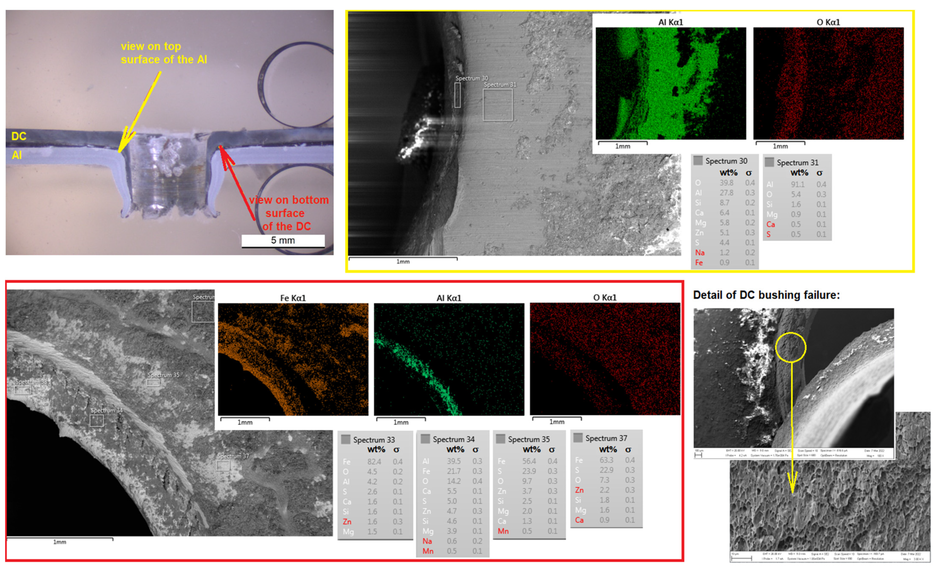
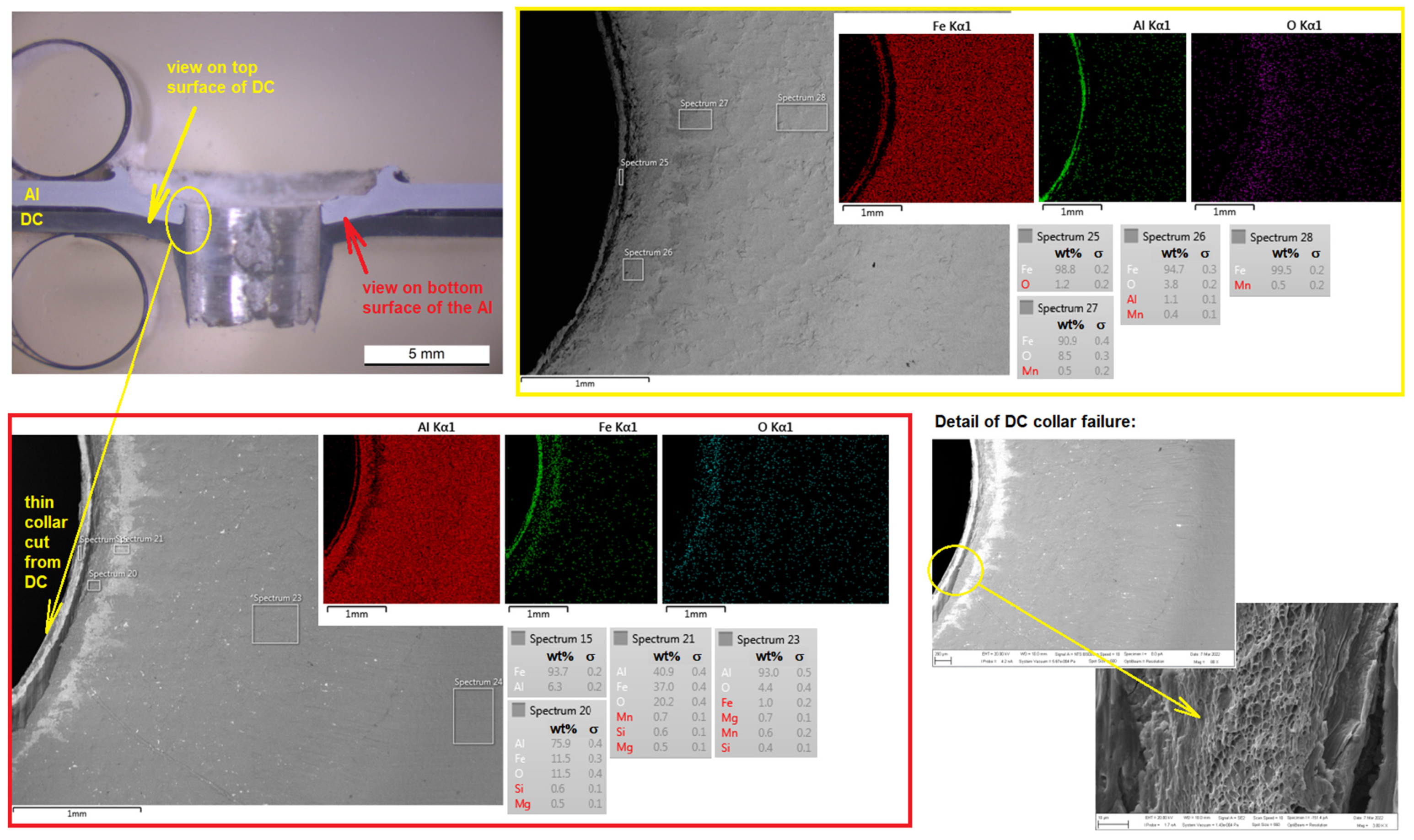
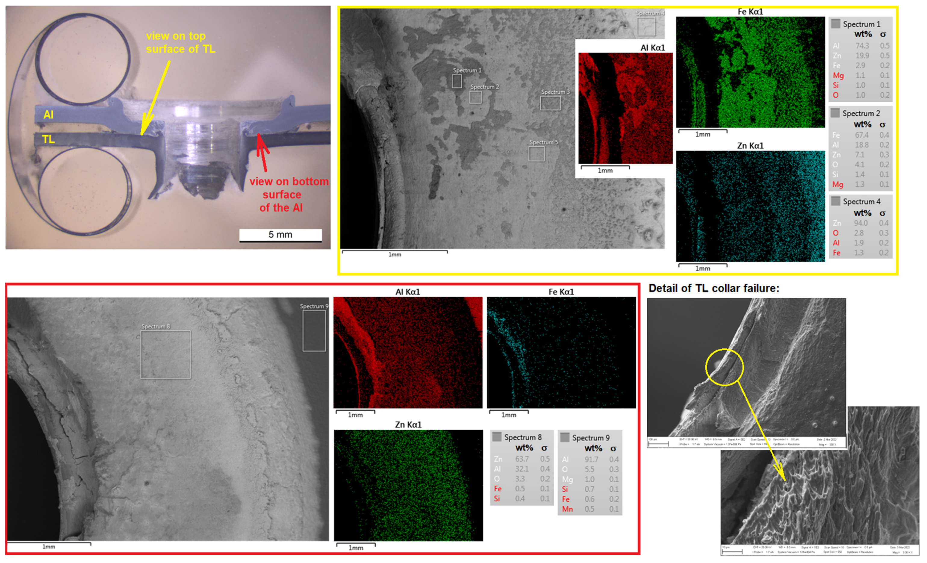
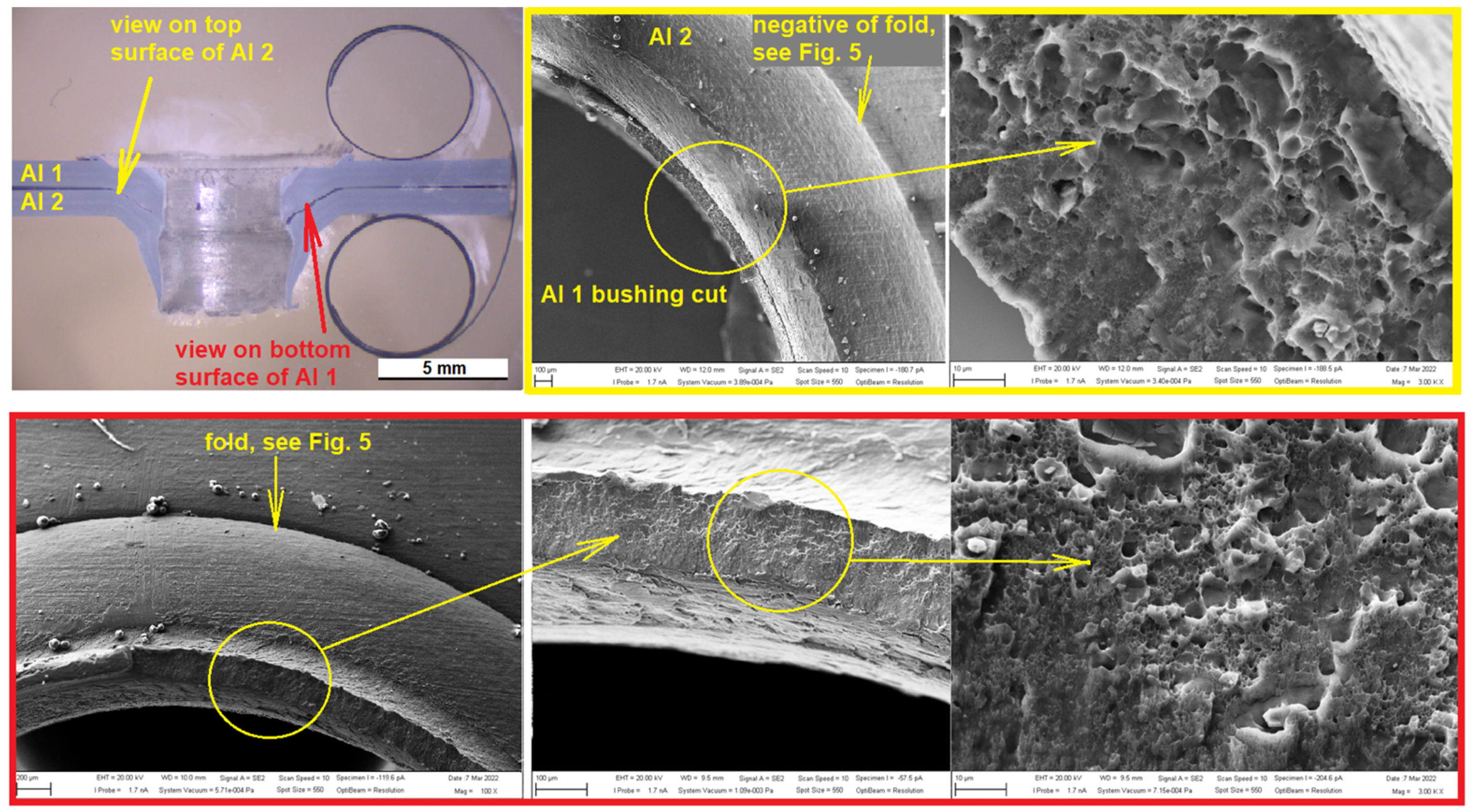
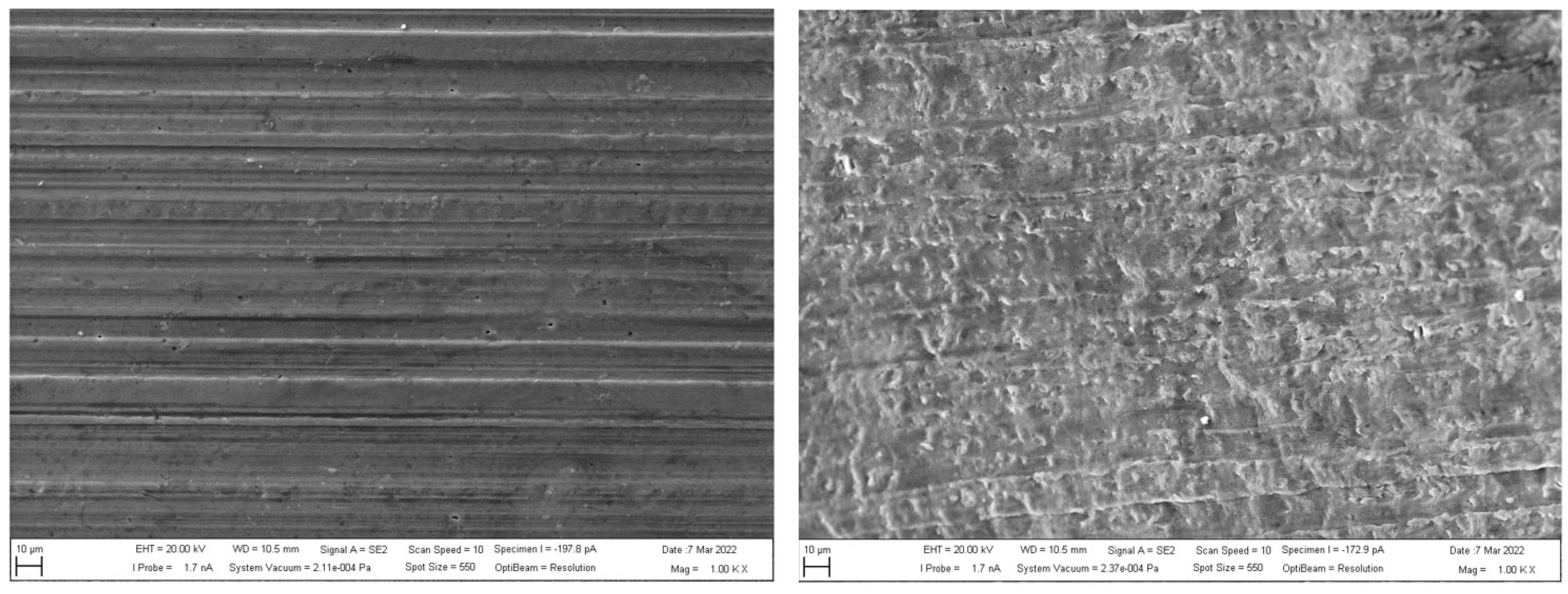
3.4. SEM Analysis of Joints
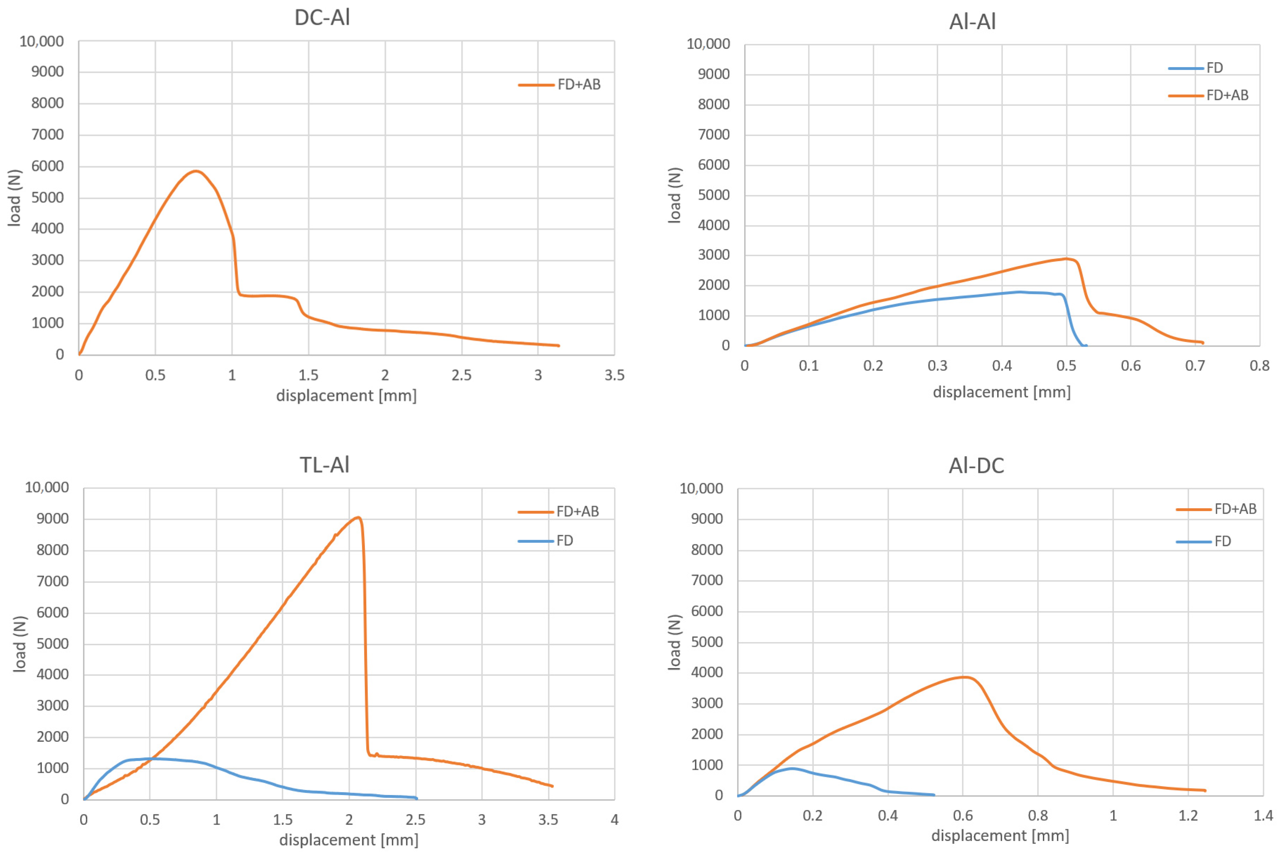
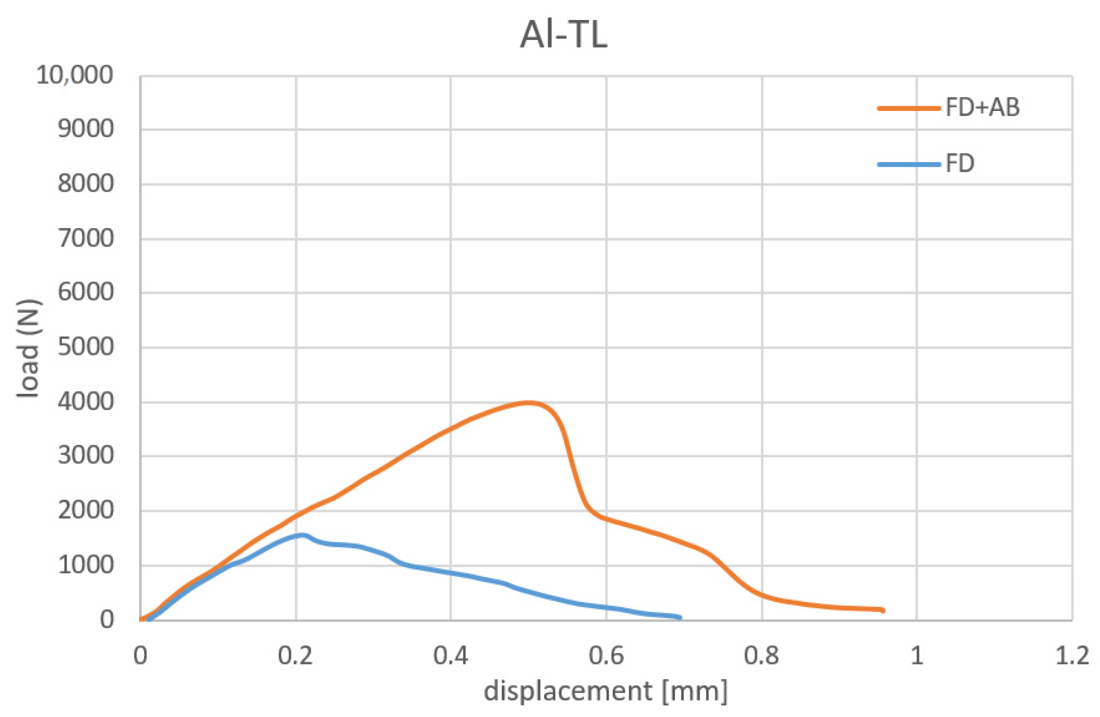
3.5. Testing of Joints
4. Discussion
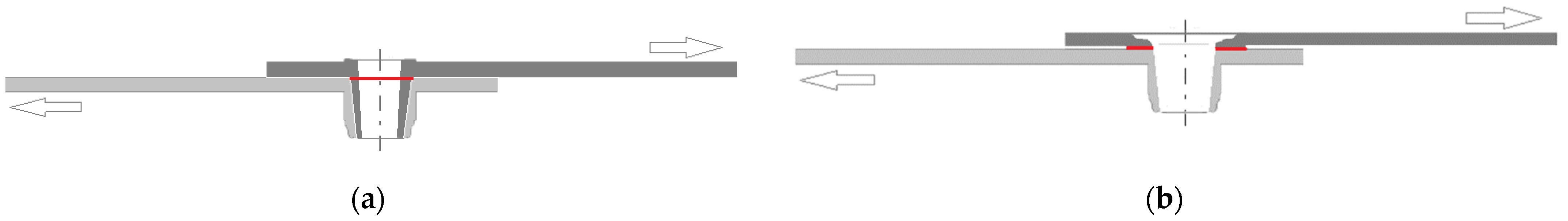
4.1. Influence of the Position of Materials When Joining
4.2. Influence of Physical Properties of Materials on the Formation of a Joint
4.3. Interaction of Materials When Joining
4.4. Effect of Tool Wear on Joint Formation
5. Conclusions
- Using flowdrill technology, it is possible to create an interference fit joint or friction joint, alone or in combination with adhesive bonding. As for the interference fit joint, the load-bearing capacity of the joint can be predicted based on the thickness of the inner bushing. The failure of the bushing in a form-fit joint combined with adhesive bonding can increase the absorbed energy and thus increase the safety of the joint. For friction joints, the bond strength between materials is uncertain.
- An important role in joining dissimilar materials is played by their physical properties, in particular the melting temperature and thermal conductivity of the materials. It is also useful to know the temperature dependence of the mechanical properties of the materials to be joined.
- Due to the decisive influence of the physical properties on the behavior of the materials at local heating, the position of the materials to be joined plays an important role.
- To create an interference fit joint with two concentric bushings, we recommend placing a material with a higher melting temperature in the upper position. Joints made in this way also exhibited the highest load-carrying capacity.
- Each material combination requires a search for optimum process parameters or a detailed thermal-strain modelling of the process.
- The combination of flowdrill technology with adhesive bonding results in a sealed joint, an increase in the load-bearing capacity of the joint, and a reduction in the risk of crevice or galvanic corrosion.
Author Contributions
Funding
Institutional Review Board Statement
Informed Consent Statement
Data Availability Statement
Conflicts of Interest
References
- European Aluminium Association: Hybrid Joining Techniques. Available online: https://www.aec.org/page/extrusion-aluminum-joining-manual (accessed on 7 February 2022).
- Messler, W.S. Joining of Advanced Materials, 1st ed.; Butterworth-Heinemann: Oxford, UK, 1993; 560p. [Google Scholar]
- Sirisalee, P.; Ashby, M.F.; Parks, G.T.; John Clarkson, P. Multi-criteria material selection of monolithic and multi–materials in engineering design. Adv. Eng. Mater. 2006, 8, 48–56. [Google Scholar] [CrossRef]
- Mori, K.; Bay, N.; Frantini, L.; Micari, F.; Tekkaya, A.E. Joining by plastic deformation. CIRP Ann. Manuf. Technol. 2013, 62, 673–694. [Google Scholar] [CrossRef]
- Martinsen, K.; Hu, S.J.; Carlson, B.E. Joining of dissimilar materials. CIRP Ann. Manuf. Technol. 2015, 64, 679–699. [Google Scholar] [CrossRef] [Green Version]
- Yang, J.; Li, Y.L.; Zhang, H. Microstructure and mechanical properties of pulsed laser welded Al/steel dissimilar joint. Trans. Nonferrous Met. Soc. China 2016, 26, 994–1002. [Google Scholar] [CrossRef]
- Wang, B.; Sun, Z.; Xu, L.; Zhang, W.; Li, X.; Zhang, H. Friction spot joining of aluminum AA5052 and short glass fiber-reinforced PPS: Effects of material properties and process parameters on joint structure and strength. J. Manuf. Process. 2021, 66, 549–564. [Google Scholar] [CrossRef]
- Evans, W.T.; Cox, C.; Gibson, B.T.; Strauss, A.M.; Cook, G.E. Two-sided friction stir riveting by extrusion: A process for joining dissimilar materials. J. Manuf. Process. 2016, 23, 115–121. [Google Scholar] [CrossRef]
- Banea, M.D.; Rosioara, M.; Carbas, R.J.C.; da Silva, L.F.M. Multi-material adhesive joints for automotive industry. Compos. B Eng. 2018, 151, 71–77. [Google Scholar] [CrossRef]
- Jeevi, G.; Nayak, S.K.; Kader, M.A. Review on adhesive joints and their application in hybrid composite structures. J. Adhes. Sci. Technol. 2019, 33, 1497–1520. [Google Scholar] [CrossRef]
- Kleiner, M.; Geiger, M.; Klaus, A. Manufacturing of lightweight components by metal forming. CIRP Ann. Manuf. Technol. 2003, 52, 521–542. [Google Scholar] [CrossRef]
- Haghshenas, M.; Gerlich, A.P. Joining of automotive sheet materials by friction-based welding methods: A review. Eng. Sci. Technol. Int. J 2018, 21, 130–148. [Google Scholar] [CrossRef]
- Fang, X.; Zhang, F. Hybrid joining of a modular multi-material body-in-white structure. J. Mater. Process. Technol. 2020, 275, 116351. [Google Scholar] [CrossRef]
- Graf, M.; Sikora, S.P.; Roider, C.S. Macroscopic modeling of thin-walled aluminium-steel connections by flow drill screws. Thin-Walled Struct. 2018, 130, 286–296. [Google Scholar] [CrossRef]
- Shalamov, P.V.; Kulygina, I.A.; Yaroslavova, E.N. ANSYS Software-based study of thermal drilling process. Procedia Eng. 2016, 150, 746–752. [Google Scholar] [CrossRef] [Green Version]
- Aslan, F.; Langlois, L.; Balan, T. Experimental analysis of the flow drill screw driving process. Int. J. Adv. Manuf. Technol. 2019, 104, 2377–2388. [Google Scholar] [CrossRef]
- Krasauskas, P. Experimental and statistical investigation of thermo mechanical friction drilling process. Mechanika 2011, 17, 681–686. [Google Scholar] [CrossRef] [Green Version]
- Miller, S.F.; Li, R.; Wang, H.; Shih, A.J. Experimental and numerical analysis of the friction drilling process. J. Manuf. Sci. Eng. 2006, 128, 802–810. [Google Scholar] [CrossRef]
- Özek, C.; Demir, Z. Investigate the friction drilling of aluminium alloys according to the thermal conductivity. TEM J. 2013, 2, 93–101. [Google Scholar]
- Kumar, R.; Hynes, N.R.J. Thermal drilling processing on sheet metals: A review. Int. J. Lightweight Mater. Manuf. 2019, 2, 193–205. [Google Scholar] [CrossRef]
- Dehghan, S.; Ismail, M.I.S.b.; Ariffin, M.K.A.b.; Baharudin, B.T.H.T.b. Friction drilling of difficult to machine materials: Workpiece mictrostructural alterations and tool wear. Metals 2019, 9, 945. [Google Scholar] [CrossRef] [Green Version]
- Streppel, A.H.; Kals, H.J.J. Flowdrilling: A preliminary analysis of a new bush-making operation. CIRP Ann. Manuf. Technol. 1983, 32, 167–171. [Google Scholar] [CrossRef] [Green Version]
- Kumar, R.; Hynes, N.R.J.; Pruncu, C.I.; Sujana, J.A.J. Multi-objective optimization of green technology thermal drilling process using grey-fuzzy logic method. J. Clean. Prod. 2019, 236, 117711. [Google Scholar] [CrossRef]
- Kaya, M.T.; Aktas, A.; Beylergil, B.; Akyildiz, K.H. An experimental study on friction drilling of St12 steel. Trans. Can. Soc. Mech. Eng. 2014, 38, 319–329. [Google Scholar] [CrossRef]
- Kanagaraju, T.; Peter, J.S.J.; Samuel, D.R.; Prakash, J.P. Optimization of drilling parameters for thrust force and torque in friction drilling process. Middle-East J. Sci. Res. 2016, 24, 1577–1582. [Google Scholar] [CrossRef]
- Shalamov, P.; Pivtsaeva, M.; Chvanova, A.; Shamgunov, A. Use of combined tools to reduce axial force during thermal drilling. Mater. Today 2021, 38, 1931–1935. [Google Scholar] [CrossRef]
- El-Blahoul, S.A.; El-Shourbagy, H.E.; El-Blahoul, A.M.; El-Midany, T.T. Experimental and thermo-mechanical modeling optimization of thermal friction drilling for AISI 304 stainless steel. CIRP J. Manuf. Sci. Technol. 2018, 20, 84–92. [Google Scholar] [CrossRef]
- El-Bahloul, S.A.; El-Shourbagy, H.E.; El-Midany, T.T. Optimization of thermal friction drilling process based on taguchi method and fuzzy logic technique. Int. J. Sci. Eng. Appl. 2015, 4, 55–59. [Google Scholar] [CrossRef]
- Schmerler, R.; Rothe, F.; Grunert, M. Hybrid Joining Using the Flow Drill Technology. Available online: https://www.researchgate.net/publication/341616091_Hybridfugen_durch_Fliesslochformen_Hybrid_joining_using_the_flow_drill_technology (accessed on 17 January 2022).
- Sønstabø, J.K.; Morin, D.; Landseth, M. Testing and modelling of flow-drill screw connections under quasi-static loadings. J. Mater. Process. Technol. 2018, 255, 724–738. [Google Scholar] [CrossRef]
- Skovron, J.D.; Prasad, R.R.; Ulutan, D.; Mears, L.; Detwiler, D.; Paolini, D.; Baeumler, B.; Claus, L. Effect of thermal assistance on the joint quality of Al6063-T5A during flow drill screwdriving. J. Manuf. Sci. Eng. (Trans. ASME) 2015, 137, 051019. [Google Scholar] [CrossRef]
- EN ISO 12996:2013; Mechanical Joining–Destructive Testing of Joints–Specimen Dimensions and Test Procedure for Tensile Shear Testing of Single Joints. ISO: Geneva, Switzerland, 2013.


| DC04 | |||||||||
| C | Mn | P | S | Fe | - | - | - | - | - |
| 0.040 | 0.250 | 0.009 | 0.008 | bal. | - | - | - | - | - |
| TL 1550-220+Z | |||||||||
| C | Mn | Si | P | S | Al | Nb | Ti | Cu | Fe |
| 0.100 | 1.000 | 0.500 | 0.080 | 0.030 | 0.015 | 0.100 | 0.150 | 0.200 | bal. |
| EN AW-6082 T6 | |||||||||
| Si | Fe | Cu | Mn | Mg | Cr | Zn | Ti | Al | - |
| 1.00 | 0.40 | 0.06 | 0.44 | 0.70 | 0.02 | 0.08 | 0.03 | bal. | - |
| Materials | YS (MPa) | UTS (MPa) | Elongation (%) | Thickness (mm) | Condition |
|---|---|---|---|---|---|
| DC04 | 197 | 327 | 39 | 0.8 | electrostatically oiled |
| TL 1550-220+Z | 292 | 373 | 34 | 0.8 | Zn coated, 100 g∙m−2 |
| EN AW-6082 T6 | 290 | 340 | 14 | 1.0 | solution treated, artificially aged |
| Material | Density (kg∙m−3) | Melting Point (°C) | Therm. Conductivity (W∙m−1∙K−1) | CTE (10−6∙K−1) | Modulus of Elasticity (GPa) |
|---|---|---|---|---|---|
| DC04, TL 1550-220+Z | 7860 | ~1500 | 45 | 10.8–12.5 | ~210 |
| EN AW-6082 T6 | 2700 | 555 | 180 | 24 | ~70 |
| Scheme of Positioning Materials in the Joint | Material in Upper Position | Material in Lower Position |
|---|---|---|
 | DC | DC |
| TL | ||
| Al | ||
| TL | DC | |
| TL | ||
| Al | ||
| Al | DC | |
| TL | ||
| Al |
| Tool Appearance | Variable | Value |
|---|---|---|
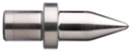 | Rotation speed | 7200 rpm |
| Tool feed rate | 200 mm/min | |
| dwell time in lowest reversal position | 0.8 s |
| Mat. in Upper Position | Mat. in Lower Position | Top View | Front View |
|---|---|---|---|
| DC | DC | 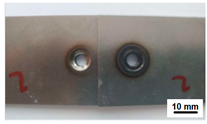 | 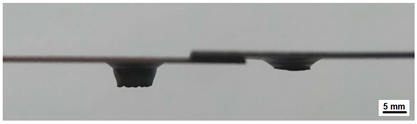 |
| DC | TL |  |  |
| DC | Al |  | 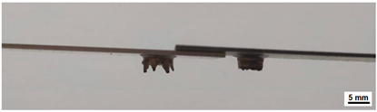 |
| TL | DC | 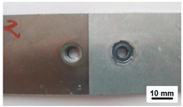 | 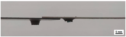 |
| TL | TL | 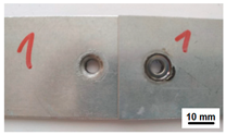 |  |
| TL | Al | 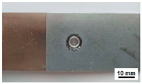 | 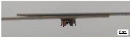 |
| Al | DC |  |  |
| Al | TL | 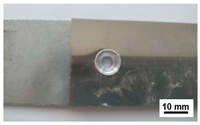 | 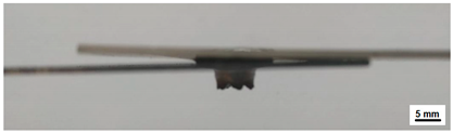 |
| Al | Al | 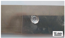 |  |
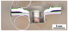
| DC in Upper Position | TL in Upper Position | Al in Upper Position |
|---|---|---|
 DC-DC | 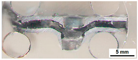 TL-DC | 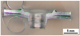 Al-DC |
 DC-TL | 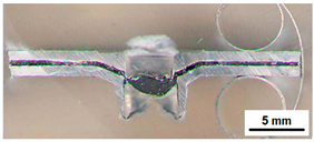 TL-TL | 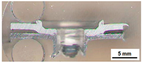 Al-TL |
 DC-Al |  TL-Al | 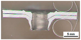 Al-Al |
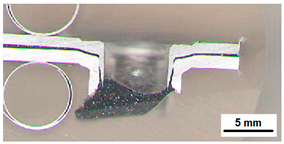
| Successfully Formed Joints with Al in Upper or Lower Position | |
|---|---|
 DC-Al | 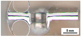 TL-Al |
 Al-DC | 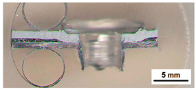 Al-TL |
 Al-Al | |
| Material Combination | Bushing | Max. Bushing Wall Thickness (mm) | Bushing Height (mm) | Compactness of Bushing | Type of Joint | Handling Resistance |
|---|---|---|---|---|---|---|
| DC-DC | inner (DC) | - | 1.6 |  | - | no |
| outer (DC) | 0.6 | 3.6 |  | |||
| DC-TL | inner (DC) | - | 1.4 |  | - | no |
| outer (TL) | 0.6 | 3.4 |  | |||
| DC-Al | inner (DC) | 0.4 | 3 |  | interference fit joint | no |
| outer (Al) | 0.8 | 2.5 |  | |||
| TL-DC | inner (TL) | - | 1.4 |  | - | no |
| outer (DC) | 0.6 | 3.4 |  | |||
| TL-TL | inner (TL) | - | 0.8 |  | - | no |
| outer (TL) | 0.6 | 3.4 |  | |||
| TL-Al | inner (TL) | 0.35 | 1.3 |  | interference fit joint | yes |
| outer (Al) | 0.75 | 3.3 |  | |||
| Al-DC | inner (Al) | - | 0.6 | - | Mechanical interlocking/friction joint | yes |
| outer (DC) | 0.6 | 3.6 |  | |||
| Al-TL | inner (Al) | - | - | - | Mechanical interlocking/friction joint | yes |
| outer (TL) | 0.6 | 3.4 |  | |||
| Al-Al | inner (Al) | - | 1.6 |  | friction joint/interference fit joint | yes |
| outer (Al) | 0.8 | 3.8 |  |
 —long compact bushing
  —long bushing with little cracks
  —short bushing
  —bushing with petals.
| Joining by Flowdrill | |||||||
|---|---|---|---|---|---|---|---|
| Combination | Fmax (N) | sFmax (mm) | 0.3Fmax (N) | s0.3Fmax (mm) | W * (Fmax) (J) | W ** (Fmax) (J) | W *** (J) |
| DC-Al | - | - | - | - | - | - | - |
| Al-DC | 834 | 0.15 | 250 | 0.35 | 0.06 | 0.08 | 0.23 |
| TL-Al | 1300 | 0.40 | 390 | 1.12 | 0.26 | 0.47 | 1.61 |
| Al-TL | 1569 | 0.24 | 471 | 0.49 | 0.19 | 0.21 | 0.53 |
| Al-Al | 1770 | 0.44 | 531 | 0.54 | 0.39 | 0.48 | 0.62 |
| Joining by Flowdrill + Adhesive Bonding | |||||||
| DC-Al | 5857 | 0.77 | 1757 | 1.40 | 2.25 | 2.49 | 5.70 |
| Al-DC | 3861 | 0.60 | 1158 | 0.80 | 1.16 | 1.35 | 2.07 |
| TL-Al | 9077 | 2.07 | 2723 | 2.13 | 9.39 | 8.32 | 10.31 |
| Al-TL | 3993 | 0.51 | 1198 | 0.74 | 1.02 | 1.14 | 1.72 |
| Al-Al | 2890 | 0.50 | 867 | 0.60 | 0.72 | 0.82 | 1.01 |
Publisher’s Note: MDPI stays neutral with regard to jurisdictional claims in published maps and institutional affiliations. |
© 2022 by the authors. Licensee MDPI, Basel, Switzerland. This article is an open access article distributed under the terms and conditions of the Creative Commons Attribution (CC BY) license (https://creativecommons.org/licenses/by/4.0/).
Share and Cite
Guzanová, A.; Janoško, E.; Draganovská, D.; Vrabeľ, M.; Tomáš, M.; Horňak, P.; Vojtko, M.; Veligotskyi, N. Investigation of Applicability Flowdrill Technology for Joining Thin-Walled Metal Sheets. Metals 2022, 12, 540. https://doi.org/10.3390/met12040540
Guzanová A, Janoško E, Draganovská D, Vrabeľ M, Tomáš M, Horňak P, Vojtko M, Veligotskyi N. Investigation of Applicability Flowdrill Technology for Joining Thin-Walled Metal Sheets. Metals. 2022; 12(4):540. https://doi.org/10.3390/met12040540
Chicago/Turabian StyleGuzanová, Anna, Erik Janoško, Dagmar Draganovská, Marek Vrabeľ, Miroslav Tomáš, Peter Horňak, Marek Vojtko, and Nikita Veligotskyi. 2022. "Investigation of Applicability Flowdrill Technology for Joining Thin-Walled Metal Sheets" Metals 12, no. 4: 540. https://doi.org/10.3390/met12040540
APA StyleGuzanová, A., Janoško, E., Draganovská, D., Vrabeľ, M., Tomáš, M., Horňak, P., Vojtko, M., & Veligotskyi, N. (2022). Investigation of Applicability Flowdrill Technology for Joining Thin-Walled Metal Sheets. Metals, 12(4), 540. https://doi.org/10.3390/met12040540