Article

Effect of Surface-Active Element Oxygen on Heat and Mass Transfer in Laser Welding of Dissimilar Metals: Numerical and Experimental Study

1
Institute of Mechanics, Chinese Academy of Sciences, Beijing 100190, China
2
School of Engineering Science, University of Chinese Academy of Sciences, Beijing 100049, China
3
Center of Materials Science and Optoelectronics Engineering, University of Chinese Academy of Sciences, Beijing 100049, China
*
Authors to whom correspondence should be addressed.
Metals 2022, 12(4), 556; https://doi.org/10.3390/met12040556
Submission received: 3 March 2022 / Revised: 21 March 2022 / Accepted: 22 March 2022 / Published: 25 March 2022
(This article belongs to the Special Issue New Welding Materials and Green Joint Technology)

Abstract

:
The effects of the surface-active element oxygen on the laser welding of 304 stainless steel (304SS) and nickel were numerically and experimentally studied in pure argon and argon–oxygen mixed gas atmospheres containing 21% oxygen (AMO). In this study, the molten pool morphology, thermal behavior, solidification phenomenon, correlation between dilution and convection flow, and microhardness of welding joints were analyzed. As a result of oxygen effects, the molten pool was deeper, the maximum temperature was higher, and the maximum flow velocity was lower in the AMO. The cooling rate (GR) and combination parameter (G/R) were studied by the direct simulation of temperature gradient (G) and solidification growth rate (R). Combined with the solidification microstructure, it was found that oxygen had little effect on grain size. The major elements Fe, Cr, and Ni within the solidified molten pool in the AMO were uniformly diluted, while the distribution of the above elements was non-homogenous in pure argon. Stronger flow and multiple directions of convection inside the molten pool contributed to uniform dilution in the AMO. The distribution of microhardness was similar to the content of Cr, and the microhardness at the substrate interface of the joint was higher in the AMO than in pure argon. The preliminary conclusions of this study provide in-depth insights into the effects of surface-active element oxygen on heat and mass transfer in laser dissimilar welding.

1. Introduction

Laser welding of dissimilar metals is considered a promising welding method because it has some advantages, such as high welding speed, narrow heat-affected zone, design flexibility, better service performance, and lower manufacturing cost [1]. It plays a vital role in the nuclear, aerospace [2], automobile [2], and chemical industries [3], as well as other engineering applications [4,5]. However, because of differences in chemical composition and thermophysical properties, such as heat capacity, thermal expansion coefficient, thermal conductivity, melting temperature, and so forth, laser dissimilar welding often confronts problems of brittle intermetallic compounds [6], formation of unmixed zones [7], improper dilution [8], unevenly mixed elements [9], asymmetric weld patterns [10], and weld imperfections, such as distortion and cracking [8], which lead to poor joint quality [11,12]. The above-mentioned challenges mainly result from unexpected heat and mass transfer in the welding process [13,14]. The fundamental study of heat and mass transfer in this investigation can be used for process control and microstructure refinement, hence, improving the weld quality.
Laser welding of dissimilar metals had been a subject for many researchers in the past decades. Landowski et al. [15] studied dissimilar welding joints between the 316L and 2304 lean duplex stainless steels, and a joint with high strength and high plasticity was obtained. Kumar et al. [16] explored the welding properties of P92 steel and Inconel 617 and found that the microstructure across the welding joint was uneven. A typical martensitic lath structure was observed on the P92 side, while the Inconel 617 side had fine equiaxed austenite grains containing carbide precipitation of Ti and Mo. The impact strength of the joint decreased after post-weld heat treatment. Sirohi et al. [7] used an Ni-based ERNiCrCoMo-1 superalloy filler to weld 9Cr-1Mo and SS304H steel plates. It easily formed an unmixed zone, and there was residual stress near the heat-affected zone. The properties of the material were improved by heat treatment after welding. Maurya et al. [3] studied the dual-phase joint of 2507 super duplex stainless steel with corrosion resistance and the nickel-based superalloy Inconel 625 with high tensile strength, which was widely used in the marine and offshore industry. They concluded that, due to differences in chemical composition, metallurgical properties, and mechanical properties of the materials, problems appeared, such as stress corrosion cracking, hydrogen embrittlement, ductility dip cracking, and migration of carbon.
Heat and mass transfer inside the molten pool was mainly affected by convection driven by the Marangoni force [17,18]. It might be possible to improve the performance of laser dissimilar welding joints by changing the Marangoni force of the molten pool. Surface-active element, such as oxygen [19,20], sulfur [21], and selenium [22], can significantly affected the temperature coefficient of surface tension, the Marangoni force, and the direction and magnitude of Marangoni convection. Consequently, fundamental studies focusing on the effects of surface-active element were worth carrying out to achieve process control and quality improvement by adjusting the content of these elements inside the molten pool. When added to the weld of 21-6-9 stainless steel (0Cr21Ni6Mn9N nitrogen-containing austenitic stainless steel) in laser and tungsten inert gas welding, selenium increased the depth–width ratio of the molten pool by over 200%, affected the shape of the molten pool by altering the temperature coefficient of surface tension, and changed the magnitude and direction of the fluid flow inside [22]. Sahoo et al. [23] compared the average metal vaporization rates per unit time and the emission spectra with pure iron samples. They found that the increase in the evaporation rate of alloy elements might be related to laser absorptivity and interfacial turbulence caused by surface-active element oxygen and sulfur. Li et al. [24] examined the influence of sulfur on the welding of 304SS thick plates with a 10 kW high-power laser. They discovered that sulfur reduced the corrosion resistance of the welding joint to an extent, but it increased molten pool fluidity, promoted heat transmission, and extended the welding depth. The addition of SiO2, TiO2, ZnO, and Fe2O3 improved weld formation, extended the penetration depth, and increased the laser absorptivity of materials in hybrid laser-arc-welded HSLA steel [25]. Experimental studies of surface-active element on welding joints have mainly focused on the influences on morphology and mechanical properties, and the fluid flow and heat transfer of the molten pool needed to be further studied.
Gan et al. [26] coupled the surface tension model and dilution model in laser-assisted additive manufacturing and found that sulfur transformed the flow mode of the molten pool, which resulted in different fusion boundaries of deposited track. Hu et al. [27] analyzed the influence of oxygen from the air on the heat transfer and fluid flow in the molten pool through an experimental study and numerical simulation of the laser welding of 42 CrMo. They found that a small amount of oxygen could significantly change the size of the molten pool. Unni et al. [28] studied the effects of oxygen content on the depth of the molten pool during the A-TIG welding of 314 LN stainless steel by numerical simulation. They found that, with the increase in dissolved oxygen in the molten pool, the velocity of fluid flow in the molten pool increased, which promoted effective heat transfer and helped to deepen penetration. Zargari et al. [29] studied heat transfer and fluid flow under the combined influence of vibration of surfactant sulfur in the filler and the double pulse gas metal arc welding of low-carbon steel, which improved the welding penetration depth. Although some progress had been made in the effects of surface-active element on the morphology and microstructure of welding joints, the effects of surface-active element on solidification and element dilution should also urgently be studied for a deep understanding of the welding process. In addition, there were few studies on the influence of surface-active element on the laser welding of dissimilar metals, especially the effects of oxygen on welding morphology, microstructure, and performance of two metals with different properties, which needed to be sufficiently studied.
For most welding processes, it is difficult to be free of oxygen due to the limitations of real manufacturing conditions, and oxygen from the air inevitably enters the high-temperature molten pool. In addition, oxygen is one of the common elements, and its content is easy to control in gaseous state. Oxygen, one of the surface-active element, is selected to study its influence on heat and mass transfer in the laser welding of dissimilar metals, to explore its mechanisms in the welding process, and to explore whether the performance of laser dissimilar welding joints is improved by adding active elements in the welding process.
In this study, the effects of surface-active element oxygen on heat and mass transfer in the laser dissimilar welding of 304SS and nickel were explored by changing the oxygen content in the gas atmosphere. A three-dimensional heat transfer and fluid flow model coupled with a sub-model of surface tension was proposed to study thermal behavior, fluid flow, and the dilution phenomenon, along with an experimental investigation. First, the simulative morphology and dimensions of the molten pool were compared with the experimental observations to verify the effectiveness of the model. The evolution of the molten pool, heat transfer, and the oxygen-induced transition of the flow pattern were analyzed. Then, the solidification process was experimentally and numerically studied based on the obtained solidification parameters through transient thermal analysis. Next, the distribution of the typical elements Fe, Cr, and Ni was tested, and the effects of surface-active element oxygen on alloy element distribution were also investigated. Finally, the microhardness of welding joints in two kinds of gas atmospheres was tested to study the effects of oxygen on mechanical properties.

2. Experimental Procedure

The 304SS and pure nickel plates (40 mm × 30 mm × 1.5 mm) were selected and utilized in the laser welding experiments of dissimilar metals. The chemical composition of the 304SS plate was shown in Table 1. The equipment used in the experiments (see Figure 1) was a triaxial laser manufacturing robot with a TRUMPF L1000.1 Nd: YAG Continuous Fiber Laser with a wavelength of 1064 nm. The laser welding experiments were carried out in pure argon and an argon–oxygen mixed gas atmosphere containing 21% oxygen (AMO, abbreviated as AMO in all sections). A diagram of the laser dissimilar welding of 304SS and nickel in a mixed atmosphere of argon and oxygen was shown in Figure 2, and the welding was along the x direction. The plates were cleaned with acetone before laser welding. The welding parameters used in the experiments were listed in Table 2. Metallographic samples were prepared through the cutting, grinding, polishing, and etching processes. An AM4115ZT Digital Microscope (Anpeng Technology Co., Ltd., Taiwan, China) was used to characterize the morphology of the molten pool. An EVO 18 Scanning Electron Microscope (SEM) (ZEISS, Heidenheim, Germany) equipped with an INCA Energy Dispersive Spectrometer (EDS) (Oxford Instruments, Oxford, UK) was used to characterize the microstructure and measure the distribution of elements. An HXD-1000 Microhardness Tester (Taiming Optical Instrument Co., Ltd., Shanghai, China) was used to measure the microhardness.

3. Mathematical Model

In this study, an improved 3D transient heat transfer and fluid flow numerical model coupled with a surface tension sub-model was developed to study the effects of oxygen on heat and mass transfer in laser dissimilar joining. Laser welding of dissimilar metals was a complex process involving heat transfer, fluid flow, solute dilution, etc. In order to simplify the simulation, the model was established under the following basic assumptions:
  • The distribution of the incident flux of the laser beam is Gaussian;
  • Liquid metal flow inside the molten pool is Newtonian, laminar, and incompressible, and the Boussinesq approximation can be employed [12];
  • The mushy zone, where the temperature is between solidus and liquidus, is assumed to be a porous medium with isotropic permeability [30];
  • Porous medium flow is assumed in the mushy zone and described by a Carmen–Kozeny relation [30];
  • The effective absorption coefficient of the laser heat source is assumed to be the function of wavelength and substrate resistivity [31].

3.1. Governing Equations

Based on the assumptions above, the mass, momentum and energy equations are coupled to calculate heat transfer and fluid flow, which are expressed in Equations (1), (2) and (6) [27,31].
The conservation equation of mass is:
ρ t + ρ u i x i = 0
where ρ and u represent the density and velocity of the fluid, respectively, t is the time, and x is the spatial coordinate.
The conservation equation of momentum is:
ρ u i t + ρ u i u j x j = x j μ u j x j p x j + F m + F f
where p is the pressure, μ is the dynamic viscosity of the liquid phase, and F m is used to describe the fluid flow in the mushy zone based on the Carmen-Kozeny assumption [30]. The expression is:
F m = A 0 u i 1 f l 2 / f l 3 + M
where A 0 is a constant related to the morphology of the mushy zone, M is a small positive constant to avoid division by zero, f l is the liquid mass fraction, and f l is given as [30]:
f l =   0   ( 0 < T < T s ) T T s T l T s   ( T s < T < T l ) 1   ( T > T l )
where T s is the solidus temperature, and T l is the liquidus temperature. The parameters applied in the calculation are presented in Table 3, and the thermal and physical properties of the materials are presented in Table 4.
F f is used to represent the change in buoyancy due to temperature changes:
F f = ρ g β T T T r e f
where g is the gravity acceleration, β T is the coefficient of volumetric expansion due to temperature changes, and T r e f is the reference temperature.
The conservation equation of thermal energy is:
ρ C p T t + u i ρ C p T x i = x i k T x i ρ Δ H t ρ u i Δ H x i  
where C p is the heat capacity, T is the local temperature, k is the thermal conductivity, and Δ H is the latent enthalpy content of fusion, which is given as:
Δ H = L f l
where L is the latent heat of fusion.

3.2. Boundary Conditions

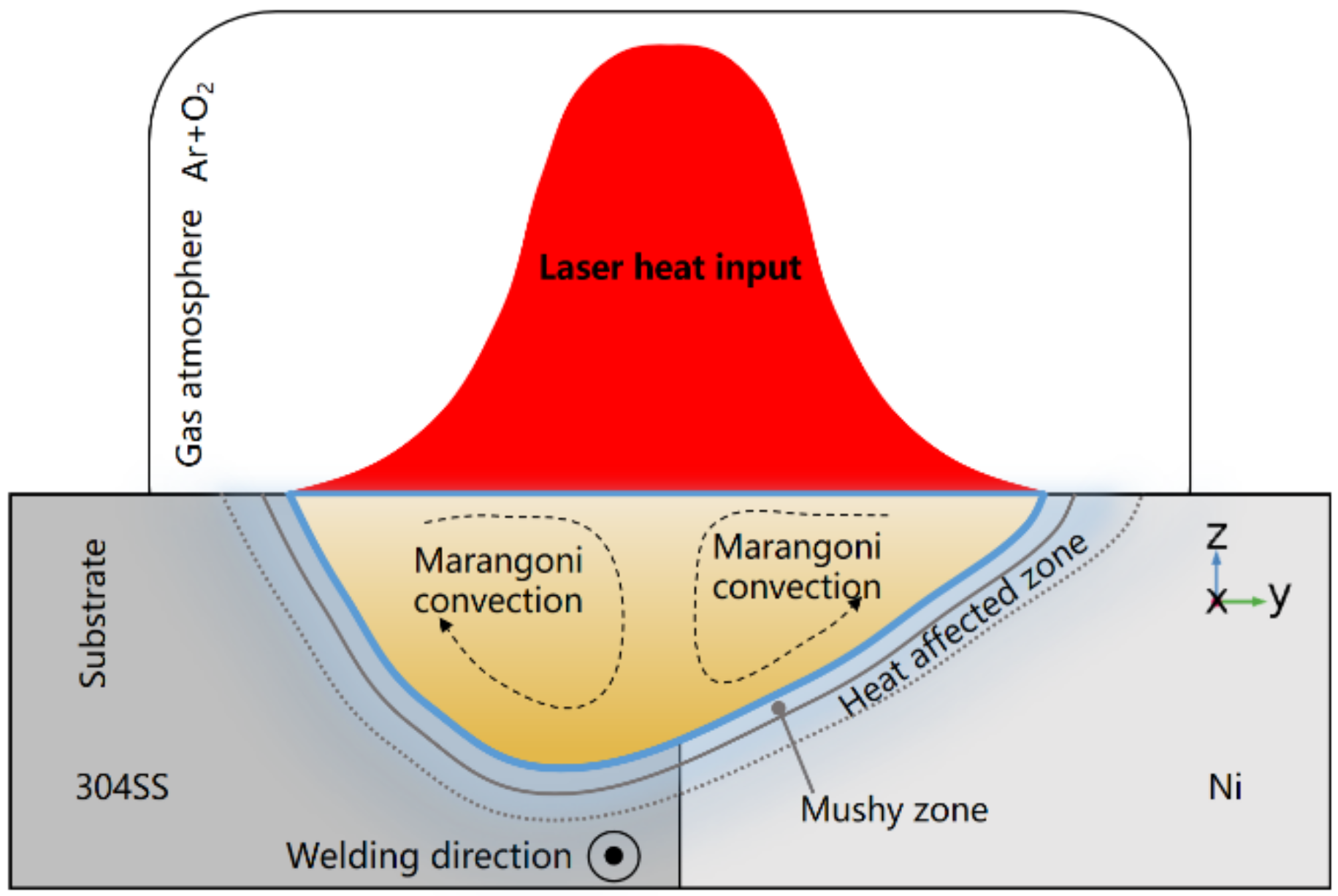
Marangoni convection mainly depends on the temperature coefficient of surface tension and temperature gradient [23]. In general, the temperature coefficient of surface tension is negative for many alloys. The temperature coefficient of surface tension may change from negative to positive in certain conditions when a surface-active element, e.g., oxygen, is included in the molten pool, resulting in transition of the flow mode for Marangoni convection [20]. The expression describing the relationship of surface tension, local temperature, and oxygen concentration is derived by Sahoo et al. [23], and its mathematical description is given by:
γ = γ m A γ T T l R u T Γ s ln 1 + k l   α i e Δ H 0 / R u   T
where γ m is the surface tension of a pure metal at melting temperature; A γ is a constant with a value of 4.3 × 10 4 N/(m·K); R u is the gas constant with a value of 8.3143 kJ/(kg·mol·K); Γ s is the surface excess at saturation with a value of 2.03 × 10 8 kg·mol/m2; k l is a constant related to the entropy of segregation with a value of 1.38 × 10 2 ; and α i is the thermodynamic activity that can be represented by oxygen content. Δ H 0 is the standard adsorption heat of 1.463 × 10⁵ kJ/(kg·mol).
Thus, the temperature coefficient of surface tension can be expressed as:
γ T = A γ R u Γ S ln 1 + K α i + K α i 1 + K α i · Γ S Δ H 0 T
K = k l e Δ H 0 / R u   T
According to Formula (9), the temperature coefficient of surface tension as the function of oxygen content and the local temperature at the gas–liquid surface can be obtained. When oxygen is negligible, the value of α i is 0, and the temperature coefficient of surface tension is a negative constant. When oxygen is included inside the molten pool, the temperature coefficient of surface tension varies with the oxygen content and local temperature and may change its sign in certain conditions.
The energy boundary at the gas–liquid surface of the molten pool can be expressed as the following:
Q f l u x = 2 η P π r 0 2 e 2 r 2 r 0 2 h c T T 0 σ b ε T 4 T 0 4
The first term, second term, and third term on the right represent heat input from laser energy, heat loss caused by heat convection, and radiation within the environment, respectively [5].
The surface shear stress caused by the change in the temperature coefficient of surface tension and temperature gradient is taken as the boundary condition of the momentum equation [27], and it is described by:
μ u z = d γ d T T x
μ v z = d γ d T T y
The calculation field is a 10 mm × 3 mm × 1.5 mm cuboid, which is divided into free triangulated mesh control bodies. Non-uniform mesh is used to improve the computational efficiency, and finer meshes are used near the heat source. The minimum grid space is 35 μm, the maximum grid space is 120 μm, and the number of grids is about 220,000. All equations are solved by PARDISO.

4. Results and Discussion

4.1. Thermal Behavior

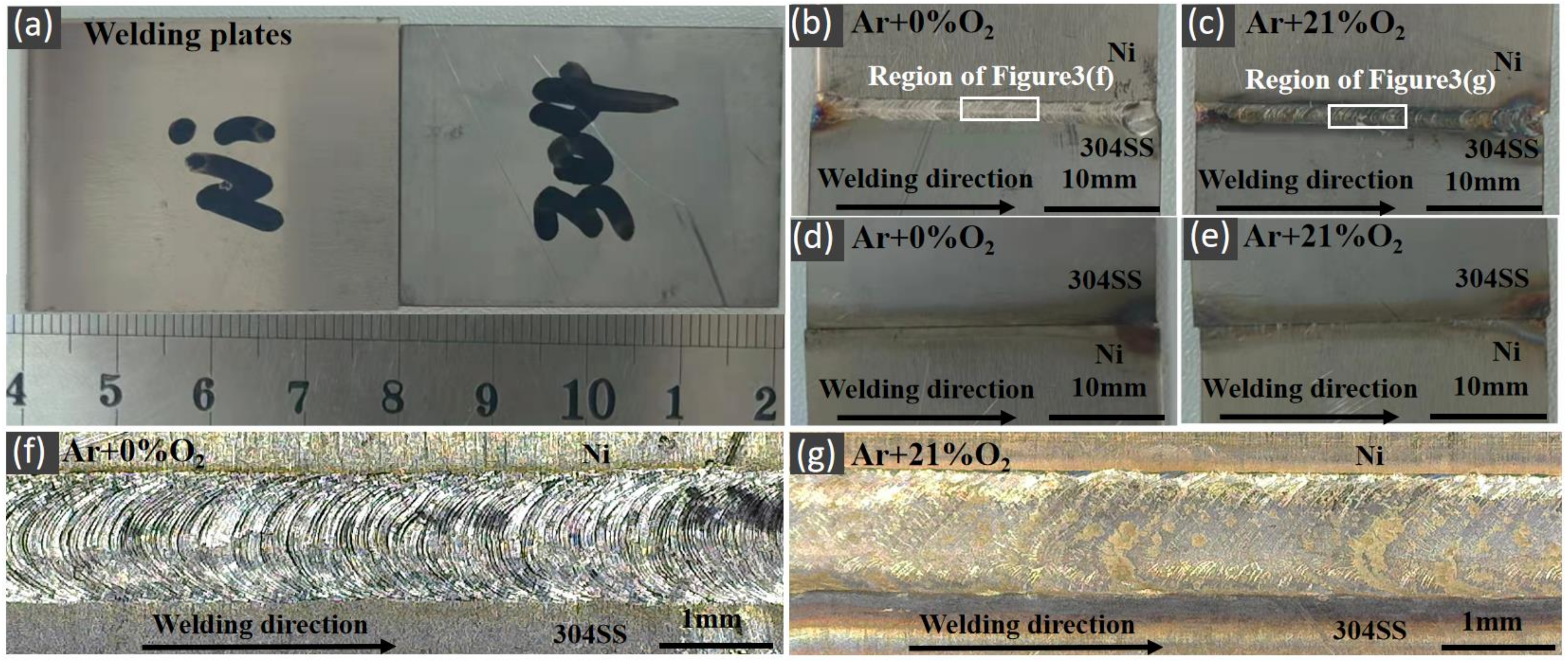
Figure 3 showed the image of a welding plate and the surface of a welding bead in different atmospheres. In order to investigate the effects of oxygen on weld morphology, especially the depth of the molten pool, conduction-mode welding was performed to show the effects of oxygen on weld pool shape clearly. Figure 3b showed the top view of a welding bead in pure argon, and the rectangular region was selected to observe the morphology of the top surface (see Figure 3f) of a welding bead in pure argon. Similarly, Figure 3c showed the top view of a welding bead in the AMO, and the rectangular region was selected to observe the morphology of the top surface (see Figure 3g) of a welding bead in the AMO. Figure 3d,e showed the back view of a welding bead in pure argon and the AMO, respectively. The weld in pure argon exhibited uniform ripple and metallic luster, while the ripple for the weld in the AMO was damaged, and the color blackened. These characteristics in the AMO were due to surface oxidation and metal spalling caused by oxygen.
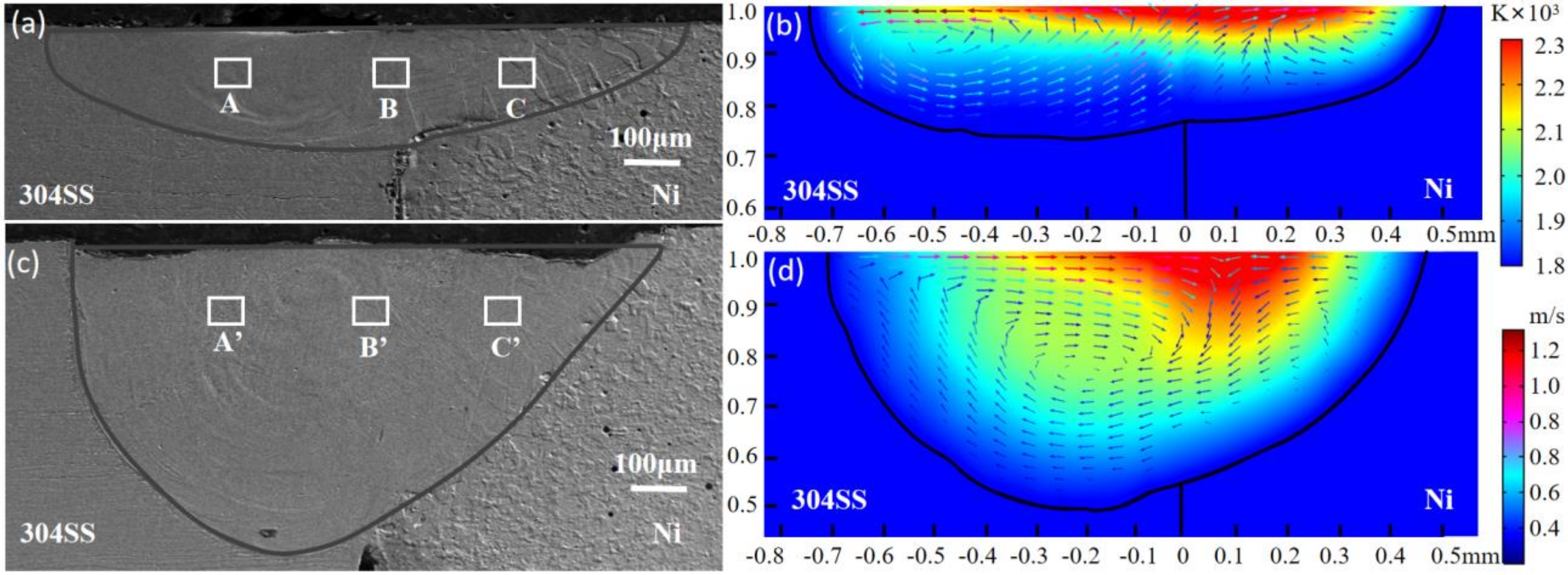
Figure 4 showed the cross-sectional morphology of the molten pool obtained from experiments and simulation. The cross-sectional morphology in pure argon was shown in Figure 4a,b, and the cross-sectional morphology in the AMO was shown in Figure 4c,d. The same process parameters were used in both the experimental and simulative studies. It can be seen that the size and morphology of the molten pool in the simulation study were similar to those from the experimental work. The molten pool was noticeably deeper in the AMO as a result of the effects of oxygen, which would be discussed in detail in the following section.
To further analyze the differences in the geometry and morphology of the molten pool, a simulative study was also carried out. The simulative temperature field and velocity distribution of fluid in both pure argon and the AMO were shown in Figure 4b,d, respectively. The color contour represented the temperature field. The direction and the color contour of the arrows represented the direction and magnitude of the fluid flow. The high-temperature region (≥2000 K) was similar to a swath in pure argon and a triangle in the AMO. The flow direction on the top of the molten pool in pure argon was outward, while the flow direction of the molten pool in the AMO was inward. The flow velocity of the molten pool was higher on the top than on the bottom because the surface tension at free surface was the dominant driver for convection flow. The maximum velocity in pure argon was higher than in the AMO. In both molten pools, the maximum flow velocity appeared on the 304SS side; there were vortices observed inside the molten pool, and the vortices in the AMO were clearly much larger. In pure Argon, there were two separate vortices on both sides, while only one was found on the 304SS side in the AMO. To gain more knowledge about the differences induced by the effects of oxygen, the heat transfer Peclet number, which represented the relative importance of convective transport and conductive transport, was introduced and described by following expression [5]:
Pe T = u m a x L / α
where u m a x is the maximum velocity of the molten pool, L is the characteristic length of the molten pool (which equaled one eighth of the molten pool radius in this study), and α is the thermal diffusivity of the material. Taking the 304SS side as an example, the value of Pe is 55.7 in pure argon and 23.1 in the AMO. Therefore, it can be concluded that convection is the main heat transfer mechanism in these two kinds of molten pools. When welding in pure argon, the flow direction is outward. The energy is transmitted to both sides, which widens the molten pool. When welding in the AMO, the temperature coefficient of surface tension is affected by oxygen, and the fluid flow that is originally outward turned inward. The energy is transferred to the bottom of the molten pool, and then the molten pool deepens.
Figure 5a,b showed the evolution of the temperature and velocity field for laser welding in pure argon and in the AMO, respectively. The substrates were melted by the energy absorbed from the laser, and, thus, the molten pool was formed. Around 60 ms, the molten pool was fully developed and stabilized, and it could be inferred that the energy from the laser was equal to the sum of absorption, energy loss caused by environmental radiation, and environmental convection. When the material was irradiated by the laser beam, the molten pool was at the initial formation stage, and there was not much difference between the molten pools in the two kinds of gas atmosphere. After 10 ms, the direction of the fluid flow in the X–Y plane was outward in pure argon, while it was opposite in the AMO. The molten pool began to deepen in the AMO, rather than pure argon, after 10 ms. The maximum velocity of fluid in pure argon was much larger than in the AMO. The maximum temperature of the molten pool in the AMO reached 3230 K in 10 ms and had a slight rise when the molten pool stabilized, but the maximum temperature of the molten pool in pure argon reached 2540 K at 10 ms and then remained stable. On one hand, the change in temperature was on account of the direction of heat transport caused by the change of flow direction. In the molten pool in pure argon, the heat was carried by outward flow to the edge of the molten pool, and the central temperature of molten pool became lower while the high temperature area became larger. In the molten pool in the AMO, the heat was carried by inward flow to the center of the molten pool, and the central temperature of molten pool became higher. On the other hand, the flow velocity of the molten pool was higher in pure argon than in the AMO, which accelerated the convective heat transfer, causing the temperature of the molten pool in pure argon drop faster and leading to the difference in the maximum temperatures. Some scholars believed that the existence of oxygen would improve the laser absorptivity of the material and lead to a rise of molten pool temperature [34]. With the development of the molten pool, the dimensions of the molten pool increased, and the dimensions for the X direction were larger than the Y direction. There was a tail for the molten pool in the opposite direction of laser movement. With time passing, the tail became bigger, and the tail in pure argon was larger. The molten pool in this study was asymmetric, and the dimensions grew faster in the direction of laser movement.

4.2. Solidification Characteristics

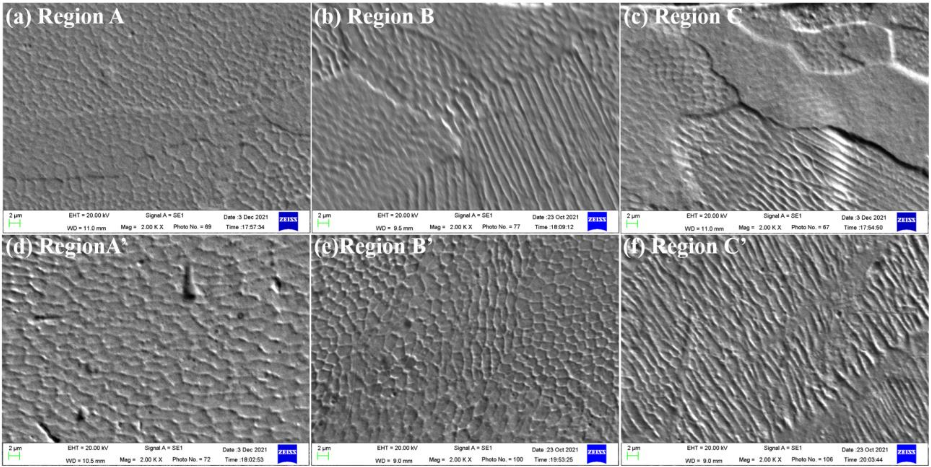
The transient thermal behavior of the molten pool determined the microstructure after solidification, and the microstructure determined the final properties of the weld [24]. In this study, three sampling regions (see Figure 4) were selected at the 304SS–nickel joint to explore the effects of oxygen on solidification. The results were shown in Figure 6. The equiaxed dendrites, the equiaxed-columnar dendrites, as well as the equiaxed-columnar dendrites occurring on the 304SS side, the substrate interface (interface between the 304SS and nickel sides), and the nickel side of the molten pool in pure argon, were observed, respectively. The microstructures of the three regions of the molten pool in the AMO from the 304SS side to the nickel side were equiaxed dendrites, equiaxed dendrites and columnar dendrites, respectively. The crystal morphology of the weld was mainly determined by the combined effects of the concentration of the solute in the alloy, the temperature gradient, and the solidification growth rate along liquid–solid interface, which would be discussed next. In the regions close to the fusion line on both sides, solidification was forward and perpendicular to the fusion line along the heat dissipation direction to form columnar dendrites [35]. In the central region of the molten pool, due to relatively uniform temperature gradient in all directions, crystal nucleus was uniformly formed to the surrounding area during solidification and crystallization to form equiaxed dendrites. In the molten pool in pure argon (as shown in Figure 4a), Region A was in the center of the 304SS side of the molten pool, while Region B and Region C were close to the fusion line. Therefore, equiaxed dendrites occurred in Region A, and equiaxed-columnar dendrites occurred in Region B and Region C. In the molten pool in the AMO (shown in Figure 4c), Region A’ and Region B’ were in the center of the molten pool, and Region C’ was close to the fusion line, so equiaxed dendrites were in region A’ and region B’, and columnar dendrites were in region C’. In addition, from Figure 6, it was shown that the microstructure in the molten pool in the AMO appeared more uniform than in pure argon.
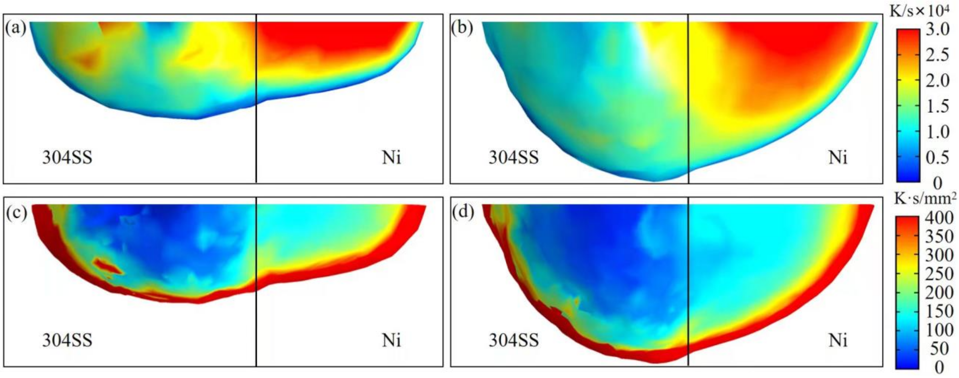
The solidification microstructure was determined by the temperature gradient (G), the solidification growth rate (R), and their combined parameters (G/R and GR) [36]. The morphology of the solidification structure was determined by the morphology parameter G/R, and the morphology changed from equiaxed dendrites to columnar dendrites to cellular dendrites with the increase in G/R. Additionally, the scale of the solidification microstructure of the molten pool was characterized by the cooling rate GR. Higher GR meaned a finer microstructure. To gain more insights into solidification behavior, the temperature gradient G and the solidification growth rate R were directly calculated from the transient thermal analysis of the developed heat transfer and fluid flow model. Figure 7 showed the calculated spatial distribution of GR and G/R in the molten pool, which were the projections of the three-dimensional solidification interface onto the cross-section. For GR, the maximum value in pure argon was similar with that in the AMO. At similar regions, e.g., region C and region C’, the cooling rate GR changed little. Consequently, it can be reasonably inferred that the microstructure sizes were similar in pure argon and the AMO. The numerical predication from the obtained solidification parameters was consistent with the experimental observations shown in Figure 6. For G/R, the distribution in the two kinds of molten pools was similar, and G/R for the nickel side was higher than the 304SS side from the calculated results. The substrate interface of the molten pool was a transition region for laser welding of different metals, and the average value for this region was greater in pure argon than in the AMO. Therefore, it can be inferred that equiaxed dendrites were more likely to occur on the nickel side, and columnar dendrites were more likely to be presented on the 304SS side. As shown in Figure 6, because the G/R value for the substrate interface of the molten pool was larger in pure argon than in the AMO, columnar dendrites existed at the substrate interface of the molten pool in pure argon, and equiaxed dendrites existed at the substrate interface of the molten pool in the AMO. The microstructures predicted by the simulation agreed well with the experimental results. In summary, the fundamental reason for the effects of oxygen on microstructure was the change in solidification behavior caused by different molten pool morphologies under the action of oxygen.

4.3. Correlation between Dilution and Fluid Flow

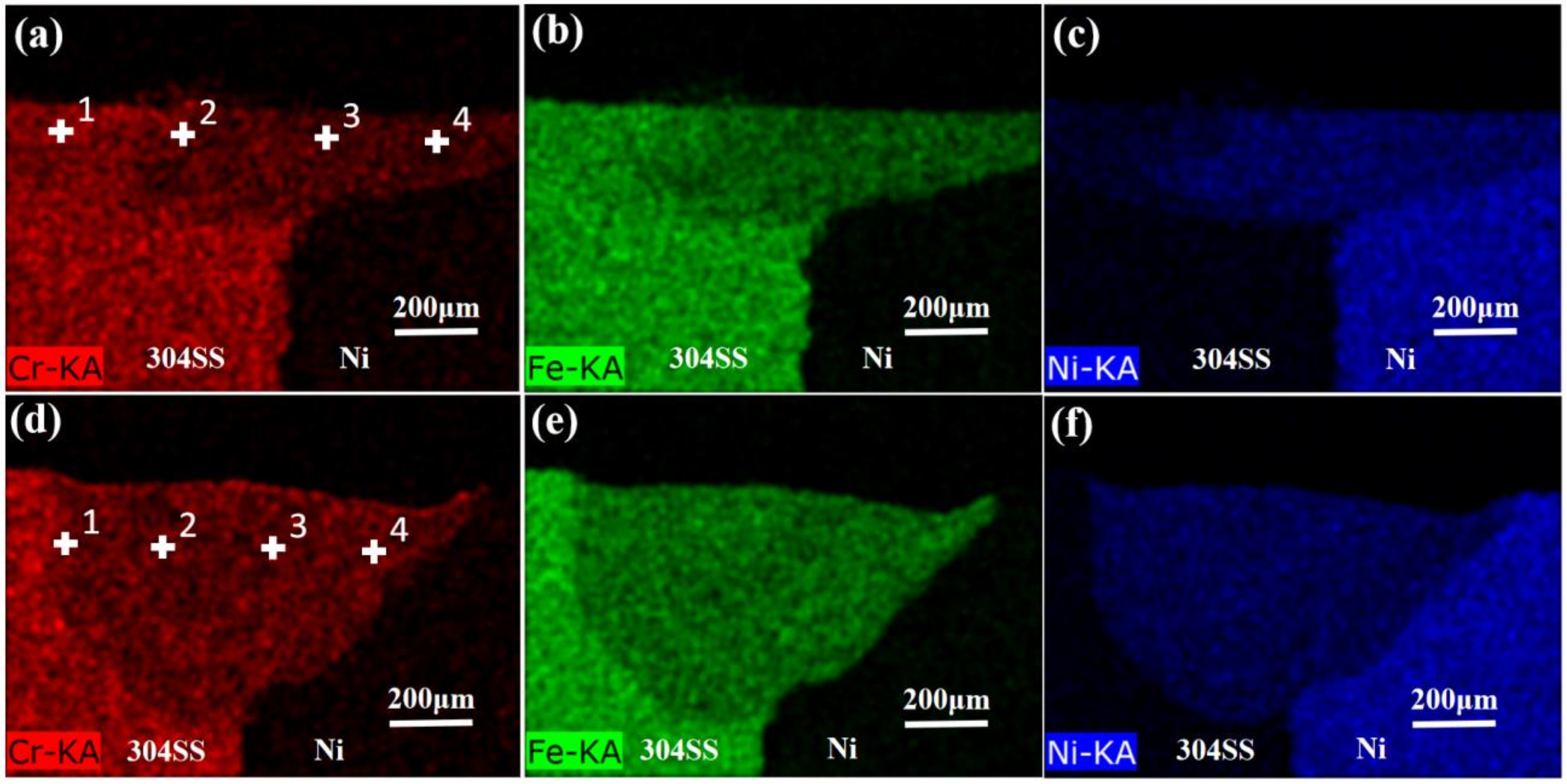
Figure 8 showed the distribution of the major elements Fe, Cr, and Ni in the molten pool by EDS mapping. To make a more reasonable illustration, the chemical compositions for four positions labeled in Figure 8 were quantitatively analyzed by EDS point scanning, and the measured results were listed in Table 5. For the molten pool in pure argon (Figure 8a–c), the dilution for main alloy elements was non-homogenous. In detail, Fe and Cr were concentrated near the boundary of the molten pool on the 304SS side, while Ni was mainly distributed near the fusion line on the nickel side. From the 304SS side to the nickel side, the concentration of Fe and Cr decreased, but it became larger for Ni. However, contributed by oxygen effects on the convection flow, the distribution of these three main alloy elements in the molten pool in the AMO, i.e., Fe, Cr, and Ni, was noticeably more uniform compared with pure argon, as depicted in Figure 8 and Table 5.
Here, the transfer mechanism of the dilution phenomenon inside the molten pool needs to be discussed to obtain further understanding about the effects of oxygen on mass transfer. Convection and diffusion are two major mechanisms of the dilution process inside the molten pool, and the mass transfer Peclet number, representing the relative importance of convection to dilution [5], can be used to help explain the differences of dilution results when oxygen is included.
Pe c = u m a x L / D
In Equation (15), u m a x and L are the same as in Equation (14), and D is the diffusion coefficient. In pure argon and the AMO, the calculated Pe c is in the order of 102; thus, the dilution process is dominated by convection and diffusion is negligible.
To analyze the oxygen-induced dilution characteristics discussed above in detail, the convection flow inside the molten pool, which was demonstrated as the major mechanism for mass transfer, was respectively plotted and investigated for different sections. The first thing should to note and explain was that the dilution phenomenon for laser dissimilar welding was not directly simulated, and the flow characteristics inside the molten pools were the modelling results from the heat transfer and fluid flow model proposed in this work. Section 4.3 focused on the correlation of fluid flow and mass transfer. All discussions regarding the dilution phenomenon were supported by the experimental observations (see Figure 8 and Table 5) and the fact that dilution inside the molten pool was dominated by convection flow. In this section, the stable molten pool at 60 ms was selected to analyze the flow characteristics at different sections. At this moment, the center of the laser heat source was located at x = 2.2 mm. As shown in Figure 9, Figure 10, Figure 11, Figure 12, Figure 13 and Figure 14, flow characteristics for the molten pool in pure argon and in the AMO were respectively plotted on the Y-Z sections (Figure 9 and Figure 10), X-Z sections (Figure 11 and Figure 12), X section, and Y section (Figure 13 and Figure 14). The magnitude of fluid flow was denoted by color map, and its direction was illustrated by white arrows.
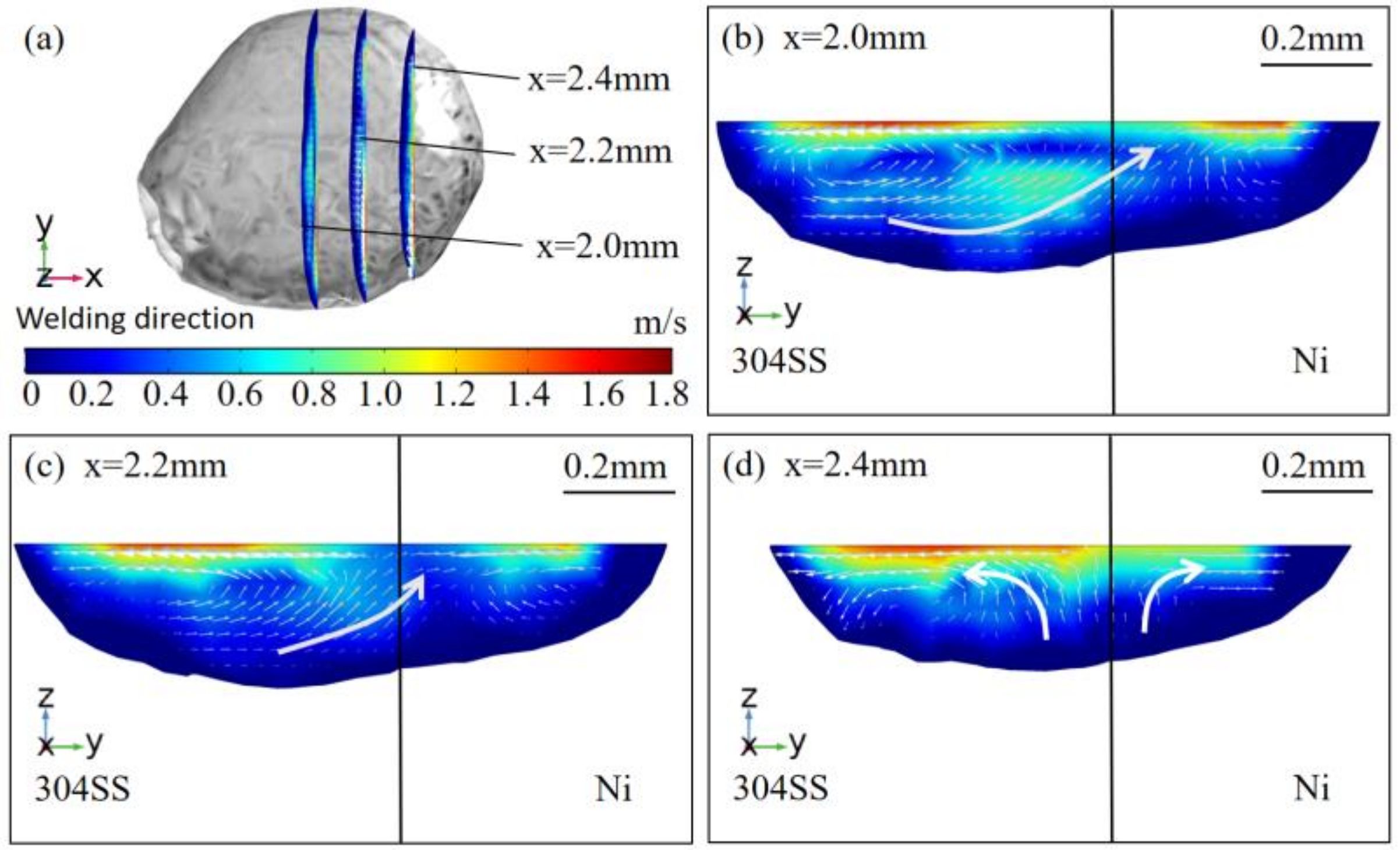
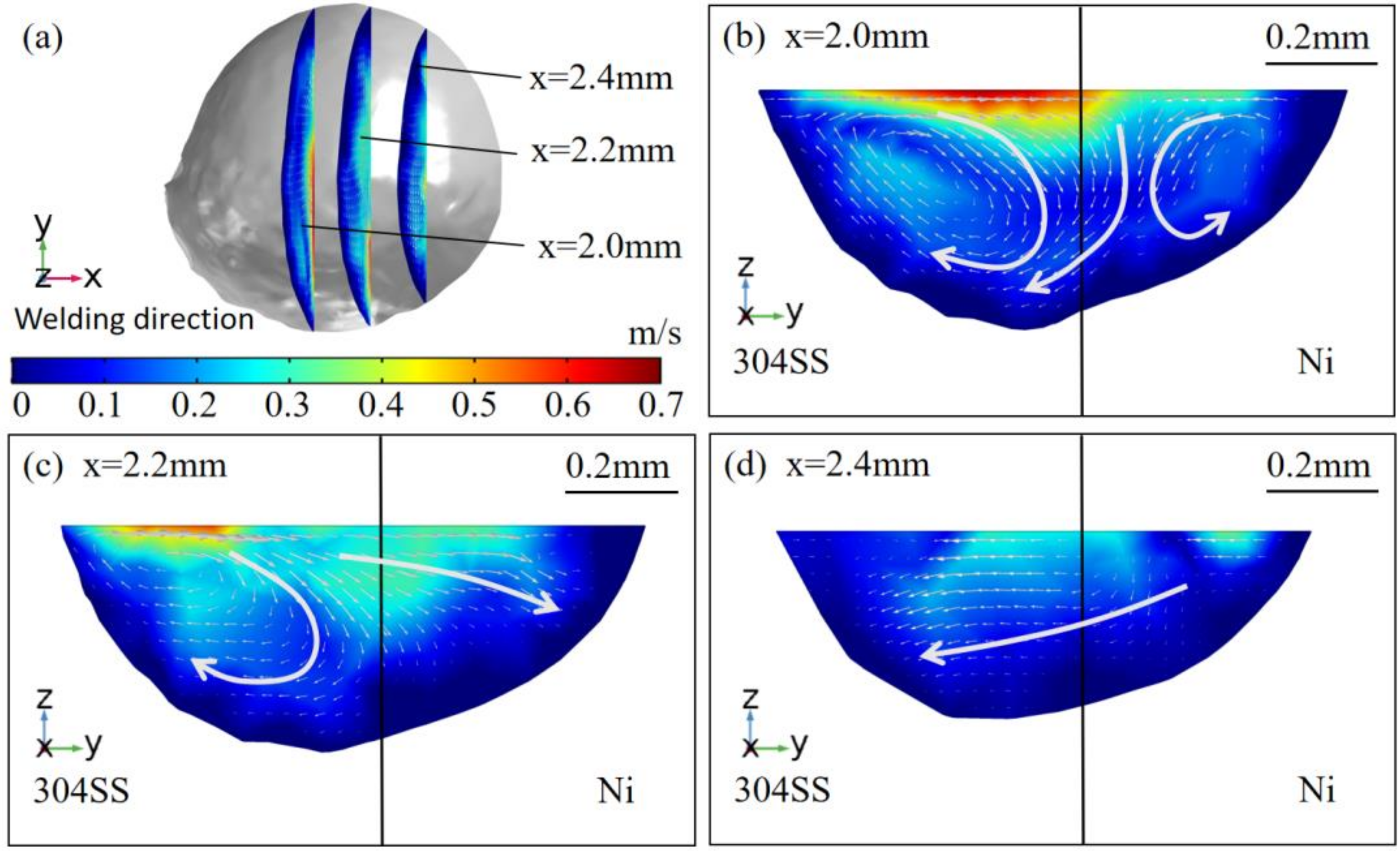
The flow characteristics at three Y-Z sections in pure argon (see Figure 9) shown in Figure 9a were depicted from Figure 9b–d, and the velocity fields at three Y-Z sections in the AMO shown in Figure 10a were plotted from Figure 10b–d. At the x = 2.0 mm plane in pure argon, there were two separate vortices on the 304SS side and the nickel side, respectively, and a branch flow from the 304SS side to the nickel side. However, for the x = 2.0 mm plane in the AMO, two larger vortices were observed on the two sides, and part of the fluid flowed from the nickel side to the 304SS side. For the x = 2.2 mm plane, the flow characteristics were similar to those at the x = 2.0 mm plane in pure argon, while the direction of the branch flow changed and flowed from the 304SS side to the nickel side in the AMO. For a comparison of flow characteristics at the x = 2.4 mm plane, the branch flow between the two sides was not found, and only two separate vortices remained for the molten pool in pure argon, while the vortices disappeared and a branch flow from the nickel side to the 304SS side was still observed in the AMO. The above-mentioned characteristics could help to explain why the elements were more uniformly diluted in the AMO. The welding process for dissimilar metals was actually the mixing of liquid metal from different substrates inside the molten pool, and branch flow between different parts largely contributed to the mixing of elements from dissimilar parts. In pure argon (see Figure 9), only the branch flow from the 304SS side to the nickel side was found in two sections. Part flow was observed in three sections in the AMO (see Figure 10): towards the 304SS side at the x = 2.0 mm plane, towards the nickel side at the x = 2.2 mm plane, and towards the 304SS side again at the x = 2.4 mm plane. It could be concluded that the branch flow at the Y-Z sections for the AMO was in multiple directions and was more complex compared with pure argon. Considering the coupling relation between convection flow and mass transfer, we predicted that elements would be more uniformly distributed in the molten pool in the AMO, and this prediction was validated by the experimental measurements illustrated in Figure 7 and Table 5. Here, it should be emphasized that both the convection flow and dilution phenomenon happened in three dimensions and should be analyzed at different sections to obtain more reasonable conclusions about the relation between fluid flow and mass transfer.
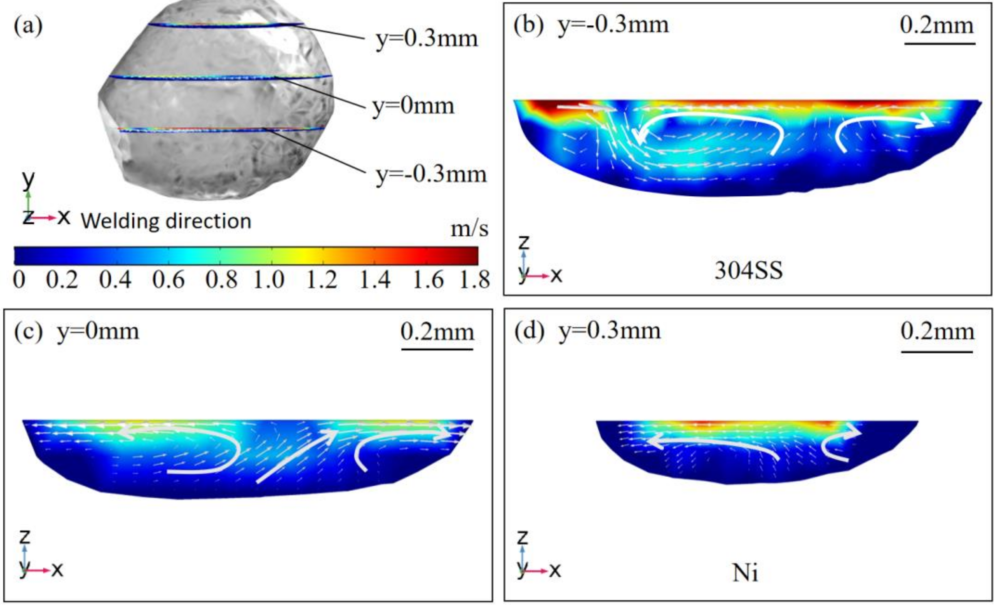
Consequently, the flow characteristics at X-Z sections were plotted and compared. Velocity fields at the three X-Z sections in pure argon shown in Figure 11a were plotted from Figure 11b–d, and the flow characteristics of the same sections depicted in Figure 12a were illustrated from Figure 12b–d. For the y = −0.3 mm plane in pure argon, three vortices were found, but the branch flow was weak. Resulting from smaller dimensions along the x direction, only one vortex was observed for the y = −0.3 mm plane in the AMO, but there was an obvious part flow towards the back of the molten pool. For the y = 0mm plane in pure argon, two vortices were observed, and the part flow was towards the front of the molten pool. In the AMO, the distribution of vortices and branch flow at the y = 0 mm plane was similar to that in pure argon. In a comparison of flow characteristics at the y = 0.3 mm plane, branch flow towards the tail of the molten pool was found in both situations, and the difference was that it was at the upper part in pure argon and the bottom part in the AMO. This bottom-part flow from the front area to the back of the molten pool was beneficial to the homogeneous mixing of alloy elements because the convection was stronger near the free surface of the molten pool (see Figure 9, Figure 10, Figure 11 and Figure 12). As a result of surface-tension-driven flow, this branch flow in the AMO could help to mix the elements from the melted 304SS and nickel substrate in the area away from the free surface. Moreover, there were also more branch flows in the X-Z sections towards different parts of the molten pool in the AMO (see Figure 12) compared with the flow characteristics in pure argon (see Figure 11), which contributed to uniform dilution along the x direction (X-Z section).
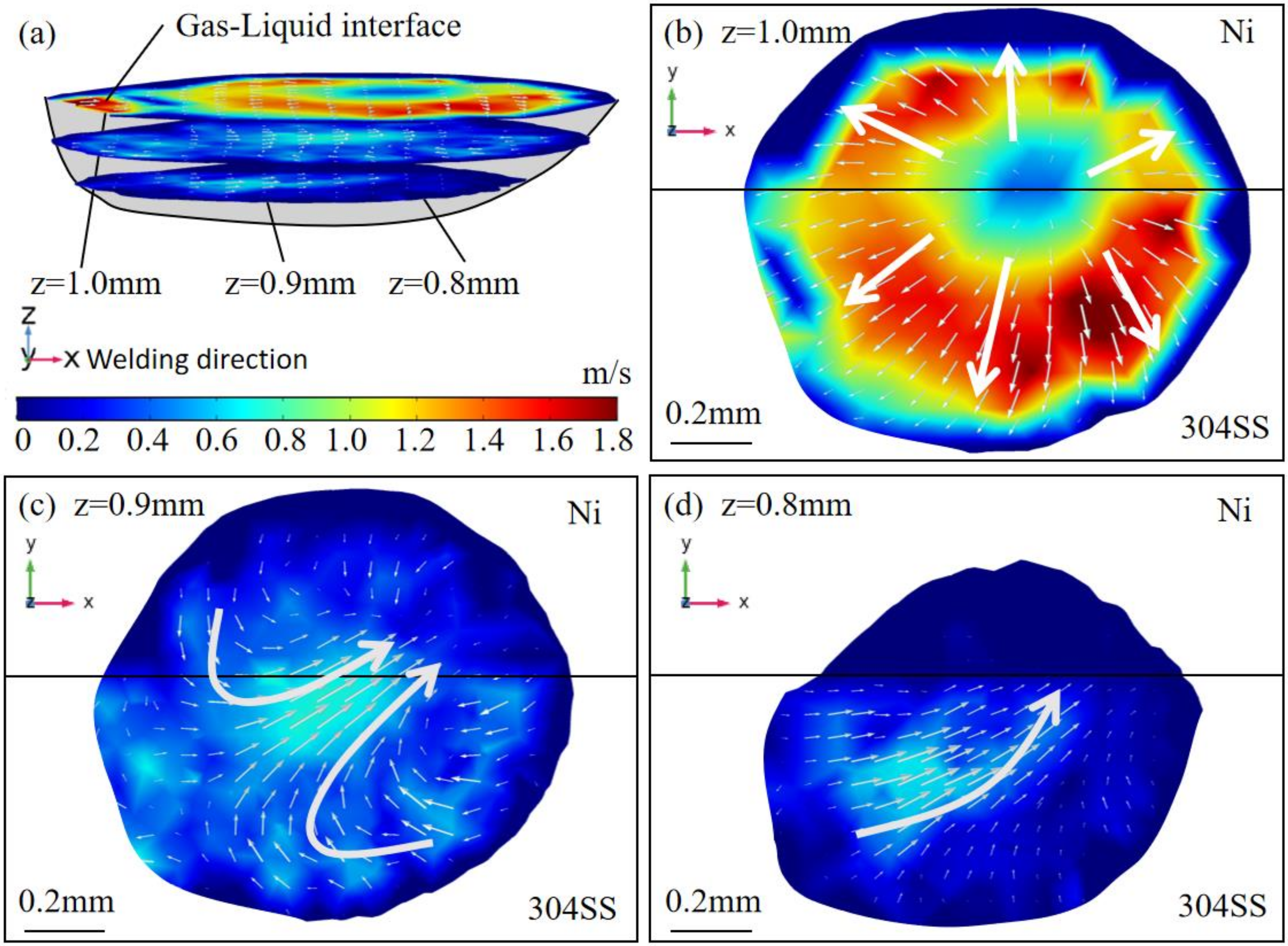
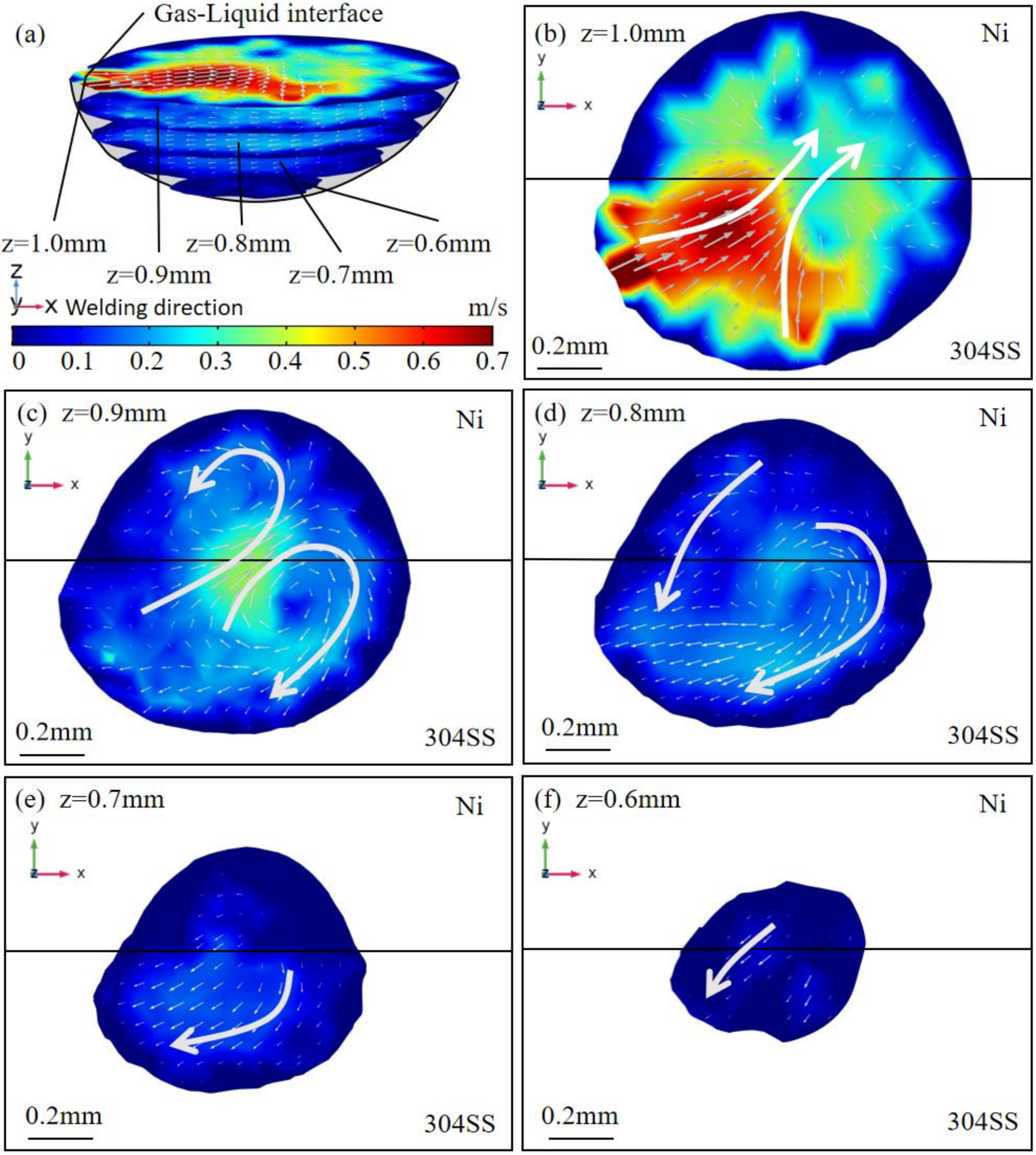
Then, the flow characteristics in the X-Y sections in pure argon (see Figure 13) and the AMO (Figure 14) were analyzed to obtain the dilution characteristics along the z direction. Due to the differences in molten pool depth, there were three X-Y planes in pure argon and five X-Y planes in the AMO. To obtain reasonable illustrations, the velocity fields of the X-Y sections in pure argon and the AMO were not compared at certain sections, but were studied at the upper part (z ≥ 0.9 mm) and the lower part (z < 0.9 mm), respectively. Results and discussions for the X-Z sections and the Y-Z section mainly helped to understand the homogeneous mixing along the y direction and the x direction for the molten pool in the AMO, and the analysis of the X-Y sections was mainly targeted at the uniform dilution along the z direction. For the upper part (z ≥ 0.9 mm) in pure argon, convection was outwards at the z = 1.0 mm plane because the temperature coefficient of surface tension was a negative constant, and the flow direction was from the high-temperature area (center) to the low-temperature area (periphery). Two vortices on separate sides, as well as a branch flow towards nickel, were observed at the z = 0.9 mm plane. For the upper part (z ≥ 0.9 mm) in the AMO, the velocity field was more complex at the z = 1.0 mm plane, with vortices and nickel-directed branch flow as a result of oxygen effects on driving forces. Similar vortices on separate sides and nickel-directed part flow were also observed at the z = 0.9 mm plane, though the convection became weaker. Thus, basic conclusions could be drawn that there were more vortices and nickel-directed branch flows for the upper part (z ≥ 0.9mm) of the molten pool in the AMO, and this would result in uniform mixing in this area. As for the bottom part (z < 0.9 mm), only one branch flow from the 304SS side to the nickel side existed at the z = 0.8 mm plane in pure argon, while 304SS-directed branch flow and a vortex in the area of the substrate interface at the z = 0.8 mm plane were observed in the AMO. Additionally, fluid flow at the bottom area in the AMO was also found (see Figure 14e,f), which was beneficial for mixing near the bottom interface of the molten pool. Supported by the flow characteristics for the planes at z = 0.8 mm, z = 0.7 mm, and z = 0.6 mm, it could also be fundamentally predicted that the elements would be more uniformly transferred at the bottom part (z < 0.9 mm). All the predictions of dilution results from the characteristics of fluid flow were well-calibrated by the EDS measurements shown in Figure 8 and Table 5.

4.4. Effect of Oxygen on Microhardness of the Dissimilar Joint

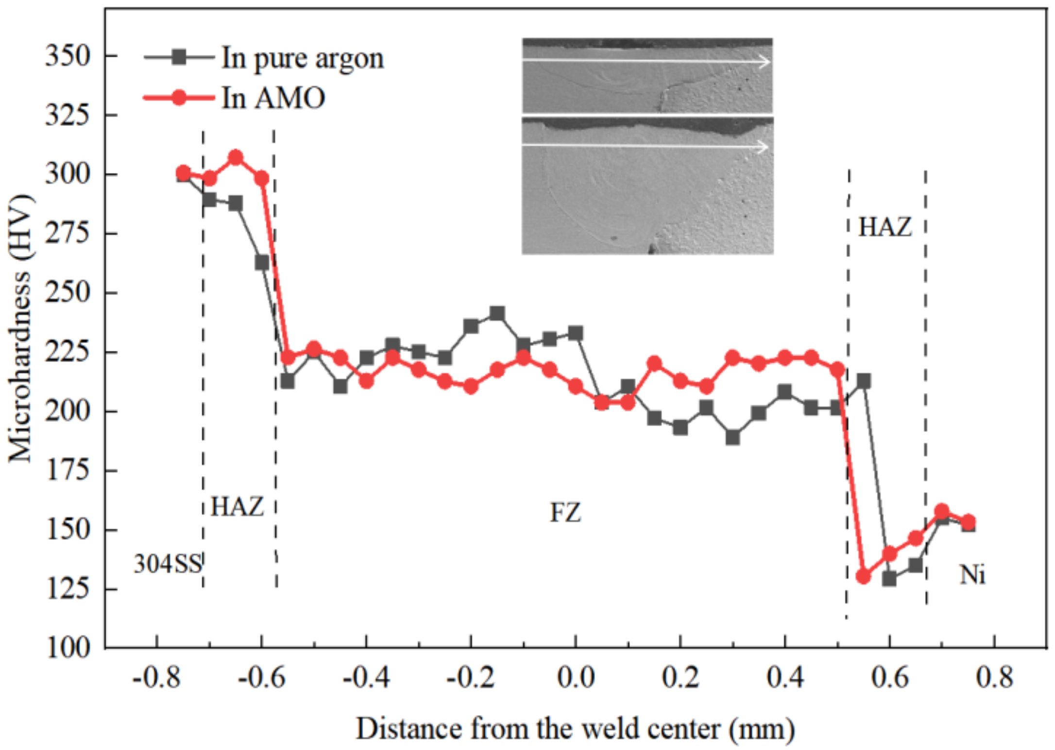
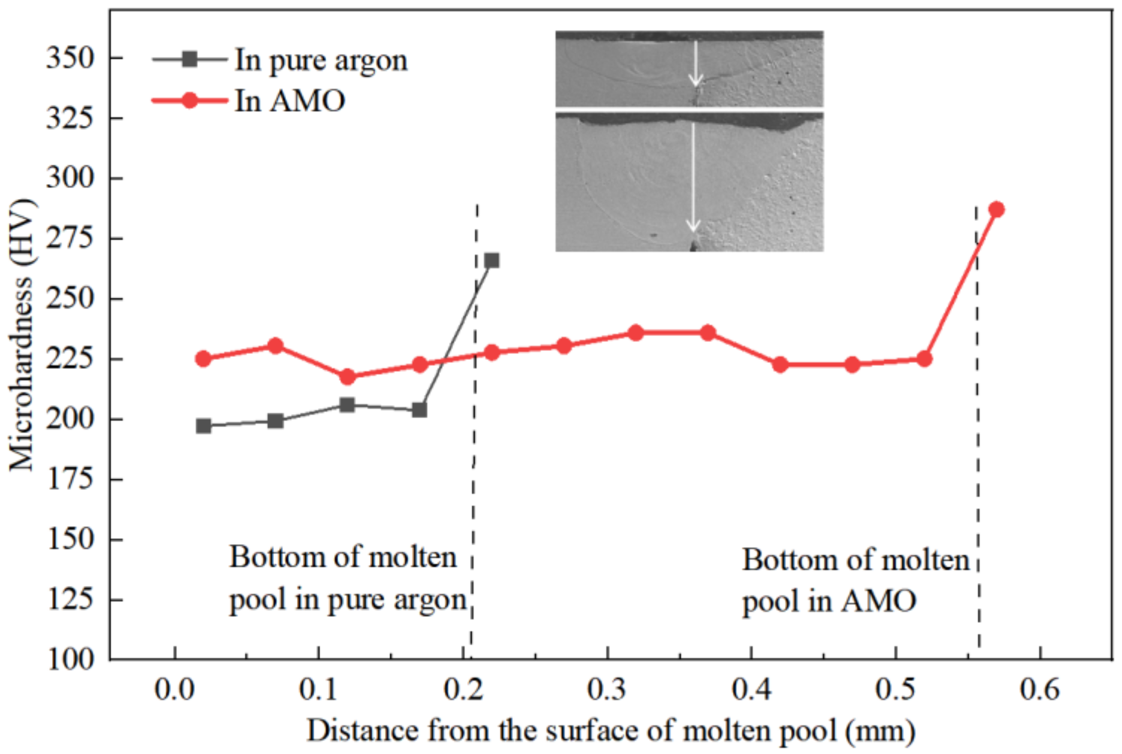
The microhardness of the welding joints was measured, taking a point every 0.05 mm for testing. When measuring in the horizontal direction, microhardness was measured at 0.1 mm below the gas–liquid surface, and the results were shown in Figure 15. The microhardness measurement for substrate interface region began at 0.015 mm below the gas–liquid surface, and the results were shown in Figure 16. Because the molten pool in pure argon was shallow, there were only four measuring points. From Figure 15, the trend of microhardness distribution of welding joints in two kinds of gas atmosphere was similar. The microhardness of the fusion zone (FZ) was higher than the nickel substrate but lower than the 304SS base metal. At the region of the FZ, the microhardness in the AMO was more uniform, and the averaged value was about 220 HV. Shown Figure 16, the microhardness of the substrate interface region in the AMO and pure argon were uniform, and the value was higher in the AMO than pure argon. The effects of the distribution of main alloys elements (i.e., Fe, Cr, and Ni) in the solidified molten pool of the Ni-based substrate were demonstrated as non-negligible for the microhardness of solidified structure [37,38]. Thus, it could be inferred that the uniform distribution of microhardness in the AMO partly resulted from the relatively uniform microstructure (see Figure 6) and homogenous dilution of alloy elements. From Figure 8 and Table 5 in Section 4.3, it could be seen that the distribution of the three main alloy elements in the molten pool in the AMO was more uniform compared with pure argon. As a result, the microhardness of the weld seam in the AMO was more uniform compared with that in pure argon. In addition, from Figure 8 and Table 5, it could be seen that the content of Cr had a similar variation tendency to the microhardness. Compared with the joint in the AMO, the joint in pure argon had higher content of Cr and higher microhardness on the 304SS side and lower content of Cr and lower microhardness on the nickel side. In the substrate interface region of the molten pool, the content of Cr at point 3 (see Figure 8 and Table 5) in the AMO was about twice as much as in pure argon. Also, the microhardness of the joint in the AMO was higher. This might be due to the formation of more hard carbides of Cr with the increase of Cr content. Additionally, the microhardness of the heat-affected zone (HAZ) was higher than that of the base metal on the 304SS side due to the self-quenching effect [13]. The microhardness of the HAZ was lower than the base metal on the nickel side, which was contributed by the coarse grains resulting from the solid phase transformation [39].
The effects of oxygen on thermal behavior, solidification characteristics, element dilution, and microhardness in the laser welding of 304SS and nickel were systematically studied by numerical and experimental methods. Further research was still needed to investigate the effects of oxygen on molten pool dynamics, to probe oxygen effects on performance of the weld joint, and to achieve process control and quality improvement.

5. Conclusions

In this study, a 3D transient heat transfer and fluid flow model was developed and experiments were conducted to investigate the effects of oxygen on molten pool morphology, solidification behavior, heat transfer, fluid flow, and dilution of alloy elements in laser dissimilar welding. The fundamental conclusions obtained from this work could be summarized as follows:
(1)
The oxygen from the gas atmosphere changed the temperature coefficient of surface tension from negative to positive, resulting in the transition of flow mode inside the molten pool from outward convection to inward convection. As a result, compared with the welding in pure argon, the molten pool was deeper, the maximum velocity was smaller, and the peak temperature was larger when oxygen was added. Additionally, the tail at the end of the molten pool was smaller in the AMO because of the convective heat transfer by the inward convection;
(2)
In both situations (AMO and pure argon), the morphology parameter G/R for solidification was smaller on the 304SS side; thus, equiaxed dendrites were observed on the 304SS side, and columnar dendrites were found on the nickel side in the solidified molten pool. The G/R at the substrate interface was smaller in the AMO, and the solidified microstructures were equiaxed dendrites for the AMO and columnar for pure Argon in this area. The cooling rate GR changed little between pure argon and the AMO, and, thus, the microstructure size was similar;
(3)
The distribution of the Fe, Cr, and Ni elements in the molten pool in the AMO was more uniform compared with that in pure argon. In the molten pool in pure argon, Fe and Ni were enriched at the edge of the 304SS side of the molten pool, where the content of Ni was small, and the three elements were relatively evenly distributed on the nickel side. There were strong flows across the substrate interface for planes at different depths of the molten pool in the AMO, which promoted the mixing of elements in the molten pool. In the molten pool in pure argon, the outward flow at the top of the molten pool caused almost no movement, while at the bottom, only the flows deriving from the metals on both sides near the substrate interface intersected and moved to the nickel side. Therefore, the elements on the nickel side of the molten pool were evenly distributed;
(4)
The microhardness distribution was more uniform in the AMO, and this partly resulted from the homogenous dilution of alloy elements.

Author Contributions

Conceptualization, B.D., Z.L. and X.H.; Data curation, B.D. and S.L.; Formal analysis, S.L. and C.T.; Investigation, G.Y.; Methodology, B.D., Z.L., G.Y., Y.B. and Z.S.; Resources, G.Y., Y.B. and X.H.; Software, B.D. and Z.L.; Validation, C.T.; Visualization, Z.S.; Writing—original draft, B.D.; Writing—review & editing, Z.L. and X.H. All authors have read and agreed to the published version of the manuscript.

Funding

The authors are grateful for financial support from the Beijing Municipal Commission of Science and Technology (No. Z181100003818015) and the National Natural Science Foundation of China (No. 11672304). Zhiyong Li is also thankful for the financial help from the Chinese Scholarship Council (CSC).

Institutional Review Board Statement

Not applicable.

Informed Consent Statement

Not applicable.

Conflicts of Interest

The authors declare no conflict of interest.

References

  1. Sun, Z.; Ion, J.C. Laser welding of dissimilar metal combinations. J. Mater. Sci. 1995, 30, 4205–4214. [Google Scholar] [CrossRef]
  2. Maurya, A.K.; Pandey, C.; Chhibber, R. Dissimilar welding of duplex stainless steel with Ni alloys: A review. Int. J. Press. Vessel. Pip. 2021, 192, 104439. [Google Scholar] [CrossRef]
  3. Sun, Z. Feasibility of producing ferritic/austenitic dissimilar metal joints by high energy density laser beam process. Int. J. Press. Vessel. Pip. 1996, 68, 153–160. [Google Scholar] [CrossRef]
  4. Yu, G.; He, X.L.; Li, S.X. Laser Manufacturing and Its Application; National Defense Industry Press: Beijing, China, 2017; pp. 93–97. ISBN 978-7-118-10984-9. [Google Scholar]
  5. Hu, Y.; He, X.; Yu, G.; Ge, Z.; Zheng, C.; Ning, W. Heat and mass transfer in laser dissimilar welding of stainless steel and nickel. Appl. Surf. Sci. 2012, 258, 5914–5922. [Google Scholar] [CrossRef] [Green Version]
  6. Fang, Y.; Jiang, X.; Mo, D.; Zhu, D.; Luo, Z. A review on dissimilar metals’ welding methods and mechanisms with interlayer. Int. J. Adv. Manuf. Technol. 2019, 102, 2845–2863. [Google Scholar] [CrossRef]
  7. Sirohi, S.; Taraphdar, P.K.; Dak, G.; Pandey, C.; Sharma, S.K.; Goyal, A. Study on evaluation of through-thickness residual stresses and microstructure-mechanical property relation for dissimilar welded joint of modified 9cr–1mo and ss304h steel. Int. J. Press. Vessel. Pip. 2021, 194, 104557. [Google Scholar] [CrossRef]
  8. Bunaziv, I.; Akselsen, O.M.; Ren, X.; Nyhus, B.; Eriksson, M.; Gulbrandsen-Dahl, S. A Review on Laser-Assisted Joining of Aluminium Alloys to Other Metals. Metals 2021, 11, 1680. [Google Scholar] [CrossRef]
  9. Yuan, R.; Deng, S.; Cui, H.; Chen, Y.; Lu, F. Interface characterization and mechanical properties of dual beam laser welding-brazing Al/steel dissimilar metals. J. Manuf. Process. 2019, 40, 37–45. [Google Scholar] [CrossRef]
  10. Zhang, L.J.; Lu, G.F.; Ning, J.; Zhu, Q.; Zhang, J.X.; Na, S.J. Effects of minor Zr addition on the microstructure and mechanical properties of laser welded dissimilar joint of titanium and molybdenum. Mater. Sci. Eng. A 2019, 742, 788–797. [Google Scholar] [CrossRef]
  11. Cao, L.; Liu, D.; Jiang, P.; Shao, X.; Zhou, Q.; Wang, Y. Multi-physics simulation of dendritic growth in magnetic field assisted solidification. Int. J. Heat Mass Transf. 2019, 144, 118673. [Google Scholar] [CrossRef]
  12. Li, Z.; Yu, G.; He, X.; Li, S.; Li, Z. Fluid flow and solute dilution in laser linear butt joining of 304SS and Ni. Int. J. Heat Mass Transf. 2020, 161, 120233. [Google Scholar] [CrossRef]
  13. Li, Z.; Yu, G.; He, X.; Li, S.; Zhao, Y. Numerical and experimental investigations of solidification parameters and mechanical property during laser dissimilar welding. Metals 2018, 8, 799. [Google Scholar] [CrossRef] [Green Version]
  14. He, X.; DebRoy, T.; Fuerschbach, P.W. Alloying element vaporization during laser spot welding of stainless steel. J. Phys. D 2003, 36, 3079. [Google Scholar] [CrossRef]
  15. Landowski, M.; Świerczyńska, A.; Rogalski, G.; Fydrych, D. Autogenous fiber laser welding of 316L austenitic and 2304 lean duplex stainless steels. Materials 2020, 13, 2930. [Google Scholar] [CrossRef]
  16. Kumar, A.; Pandey, C. Autogenous laser-welded dissimilar joint of ferritic/martensitic P92 steel and Inconel 617 alloy: Mechanism, microstructure, and mechanical properties. Arch. Civ. Mech. Eng. 2022, 22, 1–20. [Google Scholar] [CrossRef]
  17. Chakraborty, N. The effects of turbulence on molten pool transport during melting and solidification processes in continuous conduction mode laser welding of copper–nickel dissimilar couple. Appl. Therm. Eng. 2009, 29, 3618–3631. [Google Scholar] [CrossRef] [Green Version]
  18. Zargari, H.H.; Ito, K.; Miwa, T.; Parchuri, P.K.; Sharma, A. Metallurgical characterization of penetration shape change in workpiece vibration-assisted tandem-pulsed gas metal arc welding. Materials 2020, 13, 3096. [Google Scholar] [CrossRef]
  19. Lu, S.; Fujii, H.; Nogi, K. Sensitivity of Marangoni convection and weld shape variations to welding parameters in O2–Ar shielded GTA welding. Scr. Mater. 2004, 51, 271–277. [Google Scholar] [CrossRef]
  20. Zhao, C.X.; Kwakernaak, C.; Pan, Y.; Richardson, I.M.; Saldi, Z.; Kenjeres, S.; Kleijn, C.R. The effect of oxygen on transitional Marangoni flow in laser spot welding. Acta Mater. 2010, 58, 6345–6357. [Google Scholar] [CrossRef]
  21. Kidess, A.; Kenjereš, S.; Kleijn, C.R. The influence of surfactants on thermocapillary flow instabilities in low Prandtl melting pools. Phys. Fluids 2016, 28, 062106. [Google Scholar] [CrossRef] [Green Version]
  22. Heiple, C.R.; Roper, J.R.; Stagner, R.T.; Aden, R.J. Surface active element effects on the shape of GTA, laser and electron beam welds. Weld J. 1983, 62, 72. [Google Scholar]
  23. Sahoo, P.; Collur, M.M.; DebRoy, T. Effects of oxygen and sulfur on alloying element vaporization rates during laser welding. Metall. Trans. B 1988, 19, 967–972. [Google Scholar] [CrossRef]
  24. Li, S.; Deng, Z.; Deng, H.; Xu, W. Microstructure and properties of weld joint during 10 kW laser welding with surface-active element sulfur. Appl. Surf. Sci. 2017, 426, 704–713. [Google Scholar] [CrossRef]
  25. Zhang, S.; Wang, Y.; Xiong, Z.; Zhu, M.; Zhang, Z.; Li, Z. Mechanism and optimization of activating fluxes for process stability and weldability of hybrid laser-arc welded HSLA steel. Weld World 2021, 65, 753–766. [Google Scholar] [CrossRef]
  26. Gan, Z.; Yu, G.; He, X.; Li, S. Surface-active element transport and its effect on liquid metal flow in laser-assisted additive manufacturing. Int. Commun. Heat Mass Transf. 2017, 86, 206–214. [Google Scholar] [CrossRef] [Green Version]
  27. Hu, Y.; He, X.; Yu, G.; Li, S.; Zheng, C.; Ning, W. Experimental and numerical study on laser keyhole welding of 42CrMo under air and argon atmosphere. Int. J. Adv. Manuf. Technol. 2017, 90, 3555–3565. [Google Scholar] [CrossRef] [Green Version]
  28. Unni, A.K.; Muthukumaran, V. Numerical simulation of the influence of oxygen content on the weld pool depth during activated TIG welding. Int. J. Adv. Manuf. Technol. 2021, 112, 467–489. [Google Scholar] [CrossRef]
  29. Zargari, H.H.; Ito, K.; Sharma, A.; Kumar, M. Visualizing the vibration effect on the tandem-pulsed gas metal arc welding in the presence of surface tension active elements. Int. J. Heat Mass Transf. 2020, 161, 120310. [Google Scholar] [CrossRef]
  30. Voller, V.R.; Prakash, C. A fixed grid numerical modelling methodology for convection-diffusion mushy region phase-change problems. Int. J. Heat Mass Transf. 1987, 30, 1709–1719. [Google Scholar] [CrossRef]
  31. Li, Z.; Yu, G.; He, X.; Tian, C.; Li, S.; Li, H. Probing thermocapillary convection and multisolute dilution in laser welding of dissimilar miscible metals. Int. J. Therm. Sci. 2022, 172, 107242. [Google Scholar] [CrossRef]
  32. Bahrami, A.; Helenbrook, B.T.; Valentine, D.T.; Aidun, D.K. Fluid flow and mixing in linear GTA welding of dissimilar ferrous alloys. Int. J. Heat Mass Transf. 2016, 93, 729–741. [Google Scholar] [CrossRef]
  33. Bahrami, A.; Valentine, D.T.; Helenbrook, B.T.; Aidun, D.K. Study of mass transport in autogenous GTA welding of dissimilar metals. Int. J. Heat Mass Transf. 2015, 85, 41–53. [Google Scholar] [CrossRef]
  34. Li, Z.; Yu, G.; He, X.; Li, S.; Tian, C.; Dong, B. Analysis of surface tension driven flow and solidification behavior in laser linear welding of stainless steel. Opt. Laser Technol. 2020, 123, 105914. [Google Scholar] [CrossRef]
  35. Folkhard, E. Welding Metallurgy of Stainless Steels; John Wiley & Sons: Hoboken, NJ, USA, 2005; pp. 46–50. ISBN 0-471-47379-0. [Google Scholar]
  36. Kou, S. Welding Metallurgy; John Wiley & Sons: Hoboken, NJ, USA, 2003; pp. 17–20. ISBN 0-471-434919-4. [Google Scholar]
  37. Gan, Z.; Li, H.; Wolff, S.J.; Bennett, J.L.; Hyatt, G.; Wagner, G.J.; Liu, W.K. Data-driven microstructure and microhardness design in additive manufacturing using a self-organizing map. Engineering 2019, 5, 730–735. [Google Scholar] [CrossRef]
  38. Ridha Mohammed, G.; Ishak, M.; Ahmad, S.N.A.S.; Abdulhadi, H.A. Fiber laser welding of dissimilar 2205/304 stainless steel plates. Metals 2017, 7, 546. [Google Scholar] [CrossRef] [Green Version]
  39. Lehto, P.; Remes, H.; Saukkonen, T.; Hänninen, H.; Romanoff, J. Influence of grain size distribution on the Hall–Petch relationship of welded structural steel. Mater. Sci. Eng. C 2014, 592, 28–39. [Google Scholar] [CrossRef] [Green Version]
Figure 1. Experimental setup of laser welding.
Metals 12 00556 g001
Figure 2. Diagram of laser dissimilar welding of 304SS–nickel couple in an argon–oxygen mixed atmosphere.
Metals 12 00556 g002
Figure 3. Images of welding plates and the surface of welding beads in different atmospheres. (a) Welding plates; (b) top view of a welding bead in pure argon; (c) top view of a welding bead in the AMO; (d) back view of a welding bead in pure argon; (e) back view of a welding bead in the AMO; (f) morphology of the top surface of a welding bead in pure argon; and (g) morphology of the top surface of a welding bead in the AMO.
Metals 12 00556 g003
Figure 4. Cross–sectional morphology of molten pool. (a) Experimental morphology in pure argon; (b) simulative molten pool in pure argon; (c) experimental morphology in the AMO; and (d) simulative molten pool in the AMO.
Metals 12 00556 g004
Figure 5. Evolution of temperature and fluid field for longitudinal section and top surface (a) in pure argon and (b) in the AMO.
Metals 12 00556 g005aMetals 12 00556 g005b
Figure 6. Solidification microstructure at different regions of the molten pool. In pure argon: (a) 304SS side, A region; (b) substrate interface, B region; (c) nickel side, C region. In the AMO: (d) 304SS side, A’ region; (e) substrate interface, B’ region; (f) nickel side, C’ region.
Metals 12 00556 g006
Figure 7. Distribution of GR and G/R in the molten pool in laser welding. (a) Cooling rate GR in pure argon; (b) cooling rate GR in the AMO; (c) morphology parameter G/R in pure argon; and (d) morphology parameter G/R in the AMO.
Metals 12 00556 g007
Figure 8. Distribution of major elements in the molten pool measured by EDS mapping. (ac) Distribution of Cr, Fe, and Ni in pure argon and (df) distribution of Cr, Fe, and Ni in the AMO.
Metals 12 00556 g008
Figure 9. Fluid flow of the molten pool in pure argon for different X–Y sections. (a) Overview of sections in the molten pool: (b) x = 2.0 mm; (c) x = 2.2 mm; (d) x = 2.4 mm.
Metals 12 00556 g009
Figure 10. Fluid flow of the molten pool in the AMO for different Y–Z sections. (a) Overview of sections in the molten pool: (b) x = 2.0 mm; (c) x = 2.2 mm; (d) x = 2.4 mm.
Metals 12 00556 g010
Figure 11. Fluid flow of the molten pool in pure argon for different X–Y sections. (a) Overview of sections in the molten pool: (b) y = −0.3 mm; (c) y = 0 mm; (d) y = 0.3 mm.
Metals 12 00556 g011
Figure 12. Fluid flow of the molten pool in the AMO for different X–Y sections. (a) Overview of sections in the molten pool: (b) y = −0.3 mm; (c) y = 0 mm; (d) y = 0.3 mm.
Metals 12 00556 g012
Figure 13. Fluid flow of the molten pool in pure argon for different X–Y sections. (a) Overview of sections in the molten pool: (b) z = 1.0 mm; (c) z = 0.9 mm; (d) z = 0.8 mm.
Metals 12 00556 g013
Figure 14. Fluid flow of the molten pool in the AMO for different X–Y sections. (a) Overview of sections in the molten pool: (b) z = 1.0 mm; (c) z = 0.9 mm; (d) z = 0.8 mm; (e) z = 0.7 mm; (f) z = 0.6 mm.
Metals 12 00556 g014
Figure 15. Microhardness distribution in the horizontal direction for welding joints in pure argon and the AMO.
Metals 12 00556 g015
Figure 16. Microhardness distribution in the substrate interface region for welding joints in pure argon and the AMO.
Metals 12 00556 g016
Table 1. Chemical composition of the 304SS plate (atomic fraction (%)).
ElementsSiMnCrNiFe
304SS0.831.3218.438.45Bal.
Table 2. Welding parameters.
Laser PowerLaser Spot DiameterWelding SpeedGas Flow
800 W1.16 mm20 mm/s15 L/min
Table 3. Parameters applied in the calculations.
ParameterValue
Power distribution factor2
Laser absorption efficiency0.3
Ambient temperature (K)298.15
Convection coefficient (W/m2·K)100
Emissivity0.2
Stefan–Boltzmann constant (W/m2·K4)5.67 × 10−8
Table 4. Thermal and physical properties of the materials [32,33].
Property304SSNickel
Liquidus temperature (K)17201733
Solidus temperature (K)16371723
Heat of fusion (kJ/kg)261298
Specific heat of liquid (J/kg·K)800734
Specific heat of solid (J/kg·K)645617
Thermal conductivity of liquid (W/m·K)2969
Thermal conductivity of solid (W/m·K)3386
Density of solid metal (kg/m3)74508200
Density of liquid metal (kg/m3)69107700
Dynamic viscosity (kg/m·s)7.20 × 10−36.5 × 10−3
Surface tension (N/m)1.8721.778
Temperature coefficient of surface tension (N/m·K)−4.30 × 10−4−3.40 × 10⁻⁴
Liquid volume thermal expansion (K−1)1.15 × 10−51.52 × 10−5
Liquid volume concentration expansion0.0780.078
Effective mass diffusivity (m2/s)7.00 × 10−77.00 × 10−7
Table 5. Chemical compositions of four positions by EDS point scanning (atomic fraction (%)).
Position1234
Fe in pure argon61.5646.9226.1030.09
Cr in pure argon18.1413.937.68.44
Ni in pure argon20.2939.1566.361.47
Fe in the AMO53.0852.4050.4447.27
Cr in the AMO14.6014.9314.1013.52
Ni in the AMO32.3332.6635.5539.22
Publisher’s Note: MDPI stays neutral with regard to jurisdictional claims in published maps and institutional affiliations.