Article

Effects of Carrier, Leveller, and Booster Concentrations on Zinc Plating from Alkaline Zincate Baths

by
Abdul Jalil Mohammed
1,2 and
Michael Moats
1,2,*
1
Department of Materials Science and Engineering, Missouri University of Science and Technology, Rolla, MO 65401, USA
2
Materials Research Center, Missouri University of Science and Technology, Rolla, MO 65401, USA
*
Author to whom correspondence should be addressed.
Metals 2022, 12(4), 621; https://doi.org/10.3390/met12040621
Submission received: 25 February 2022 / Revised: 24 March 2022 / Accepted: 31 March 2022 / Published: 3 April 2022

Abstract

:
Organic additives are required for alkaline zincate plating baths to obtain an acceptable coating on steel for corrosion protection. The effects and possible interactions of three commercial additives (Eldiem Carrier, Eldiem Booster, and Bright Enhancer 2× on zinc electrodeposition from a high-concentration alkaline zincate bath were investigated. Visually acceptable deposits were produced within the current density range of 130 to 430 A m−2 for most additive conditions examined. Over concentration ranges examined, decreasing the booster concentration led to brighter zinc deposits, and an interaction between the carrier and the booster was detected. The additives fostered the formation of compact and adherent coatings as illustrated by scanning electron microscopy. Throwing power and current efficiency were not impacted by the additives over the concentration ranges examined. Linear sweep voltammetry proved that the additives increased the overpotential for zinc deposition. The additive combination that produced the brightest deposit also demonstrated the strongest adsorption of additives in linear sweep voltammetry.

1. Introduction

Steel’s strength, ductility, and low cost have made it a preferred choice in the construction and manufacturing of a wide variety of structures. A major disadvantage of steel is that it corrodes when exposed to oxygen and moisture. To overcome this disadvantage, steel is coated with a less corrosive metal, paint, or enamel to provide corrosion protection. Zinc provides excellent protection to steel due to its relatively slow corrosion rate over a wide range of conditions [1].
The most common industrial methods for zinc coating of steel are hot-dip galvanizing and electrogalvanizing. Continual technological improvements make it difficult to conclude in favor of one process over the other. However, hot-dip always includes some surface alloying by diffusion, and the deposit thickness is less easily controlled than in electrogalvanizing [2]. Electrogalvanizing is performed at a lower temperature than hot-dipping and does not affect the mechanical property of the steel substrate. It can also produce a uniform, bright, and adhering coating to the steel. Electrogalvanizing is often preferred over hot-dipping when a decorative finish is desired [3].
Cyanide-based zinc baths dominated the electrogalvanizing industry for many years due to their efficiency and ease of utilization, but their use has gradually declined over time due to the toxicity of cyanide and increasingly stringent environmental regulations [4,5]. For these reasons, there has been a shift towards the use of less toxic acid zinc and alkaline zincate (noncyanide) baths.
Alkaline zincate baths solve the problems of toxicity of cyanide-based baths and the inherent corrosivity of acid baths on equipment while exhibiting a reasonable throwing power [6,7]. However, the absence of the complexing effect of cyanide results in the production of powdery nonadherent deposits from alkaline zincate baths [8]. To produce smooth and adherent zinc coating, plating additives are required in alkaline zincate baths.
The most common plating additives are classified as carriers, levellers, and brighteners [9]. Classifications are based on the properties of additives (such as chemical nature) and their impact on the zinc electrodeposit, such as grain refiner and smoothing agent [9]. Positively charged additives can assist the negatively charged zincate ion approach and absorb onto the negatively charged cathode [10]. For alkaline zincate baths, carriers such as polyvinyl alcohol [11,12], polypropylene imine, and sodium potassium tartrate [13] polarize the cathode, which results in grain refinement. While carriers refine the grains, they do not necessarily produce a bright finish [14]; therefore, brighteners are used to complement the effect of the carrier to produce a bright deposit [15]. Polyamines [16,17] and aldehyde [18] are widely used as brightening agents in alkaline zincate baths. Levellers adsorb onto high points during deposition to promote deposition in recesses, which tends to result in a more uniform coating thickness [17]. Condensation products such as amines and aldehydes have been used to produce additives that have both brightening and levelling capabilities [19]. Additives are known to have synergistic effects on the microstructure and appearance of zinc coatings [20,21]. The specific chemical compounds used as additives in large industrial alkaline zinc plating facilities are proprietary.
The zinc and sodium hydroxide concentrations of alkaline zincate baths also have profound effects on the nature of the deposit. Typical concentration ranges are 6 to 22 g L−1 zinc and 60 to 150 g L−1 NaOH [8]. According to Wantotayan et al. [22], Zn and NaOH concentrations affect the coating thickness and throwing power. Sodium hydroxide also influences the conductivity of the bath and current efficiency. Nayaka and Venkatesha [19] studied the effect of Zn and NaOH on the current density range, which produced acceptable deposits and determined that increasing the Zn and NaOH content widened the operating window.
Scott and Moats [23] studied the effects of low concentrations of three commercial additives: Eldiem Carrier, Eldiem Booster, and Bright Enhancer 2x (leveller) in an unusually high Zn (37.5 g L−1) and NaOH (210 g L−1) bath relative to other literature sources. The study revealed that improvements to the zinc deposit appearance could be made, but none of the conditions examined produced desirable bright and shiny deposits. Therefore, in this study the same commercial additives and bath chemistry were used but at higher additive concentrations. Both the individual and synergistic effects of these commercial additives on deposit brightness, cathodic polarization, throwing power, current efficiency, and surface morphology were investigated.

2. Materials and Methods

Plating baths or electrolytes were prepared by dissolving high-purity zinc balls (Belmont Metals, New York City, NY, USA) into a NaOH solution. Analytical-reagent-grade NaOH (Fisher Chemicals, Hampton, NH, USA) and deionized and distilled water (18.3 MΩ.cm) were used to prepare the solution. The solution was then treated with special high-grade (SHG) zinc dust (Purity Zinc Metals) at a concentration of 3 g L−1. After mixing the dust with the solution for 120 min at room temperature, the solution was filtered using Whatman grade 1 qualitative filter paper to remove any residual solids. Electrolysis using a mild steel anode and stainless-steel cathode was then performed with the filtrate at a current density of 10 A m−2 for 5 h to further rid the solution of metal contaminants. The zinc and sodium hydroxide concentrations were determined by titration and then diluted to 37.5 g L−1 zinc and 210 g L−1 NaOH using de-ionized water.
Three commercial additives—Eldiem Carrier, Eldiem Booster, and Bright Enhancer 2× (leveller)—were used in this study without further purification. The plating additives were added to the electrolyte and preheated for 60 min prior to each experiment. All experiments were performed at 40 °C (±2 °C).
A target ratio of 5:2:1 for carrier, leveller, and booster, respectively, was indicated by Scott as producing the best zinc finish at low total additive concentration (~0.07%) [24]. Preliminary Hull cell experiments were performed using the 5:2:1 additive ratio with total additive concentrations at 1%, 2%, 3%, and 4%, which are more typical of commercial levels for other additive systems [8]. From these results, 1% (bath I) additive concentration with a ratio of 5:2:1 was selected as the center point for a 23 full factorial design of experiments to examine the individual effects of these additives along with possible interactions [25] on Hull cell plating appearance, deposit structure, throwing power, current efficiency, and electrochemical response. Low and high values were selected at −50% and +50% of the midpoint concentrations producing the design of experiments shown in Table 1.

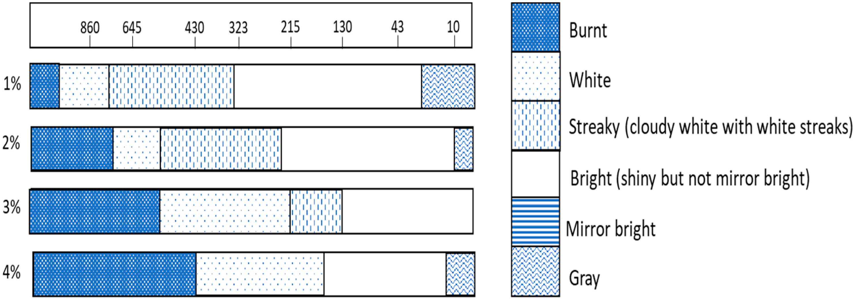
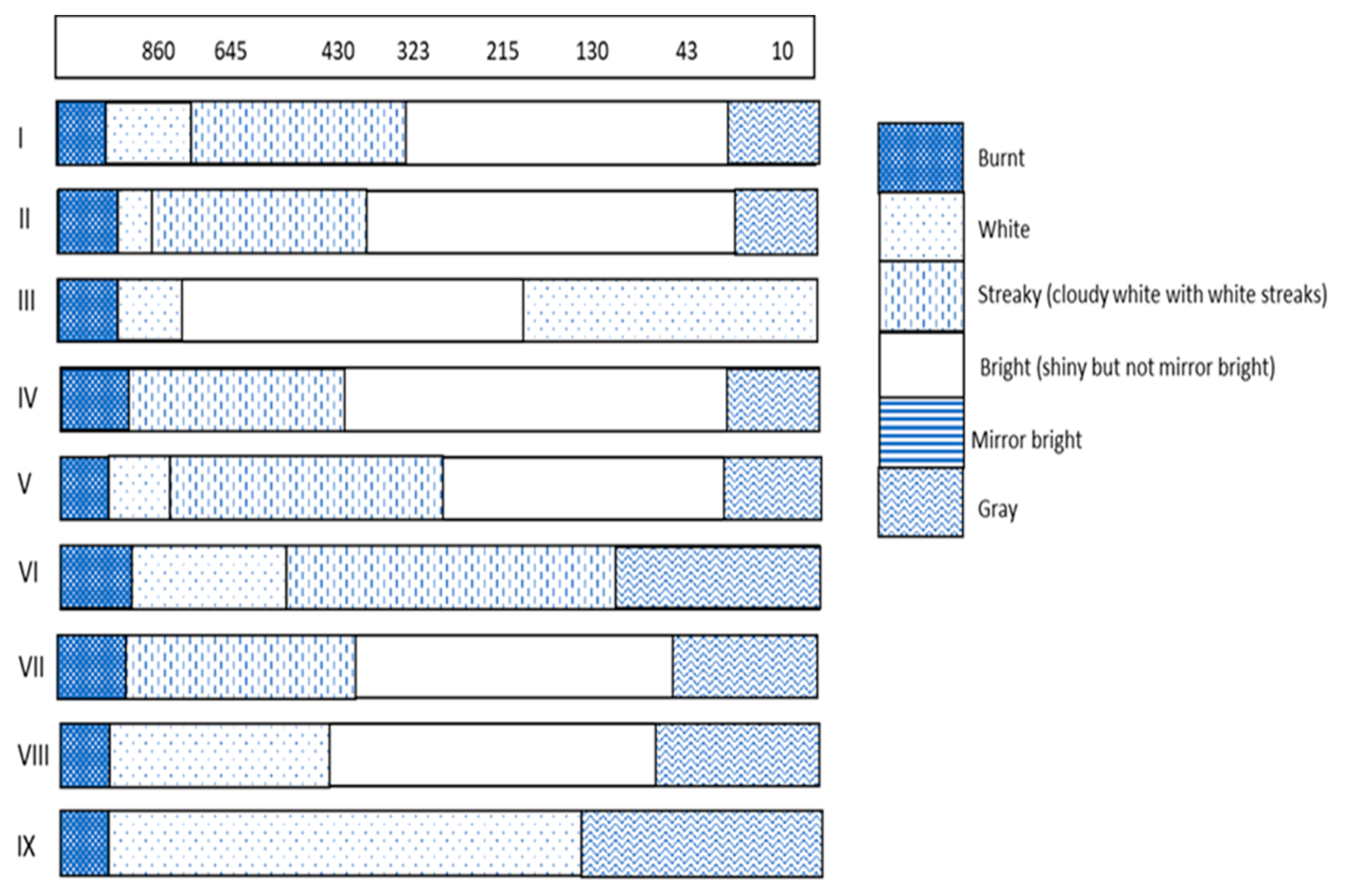
2.1. Hull Cell Studies

A 267 mL Lucite Hull cell (Kocour, Chicago, IL, USA) was used with a mild steel mesh anode. The cathode was a zinc-coated 1010 steel panel with dimensions of 10 cm × 7.6 cm. Prior to each experiment, the cathode was dipped in 50% v/v HCl to strip off the zinc coating and then rinsed with DI water until a water-break-free surface was observed. A current of 2 A was applied using an Extech (Model 382275, Nashua, NH, USA) for 5 min without external electrolyte agitation. After plating, the cathode was rinsed with deionized water, dipped in 0.5% nitric acid for 10 s, and then rinsed again with deionized water. The rinsed sample was air-dried to avoid water stains on the zinc coating.

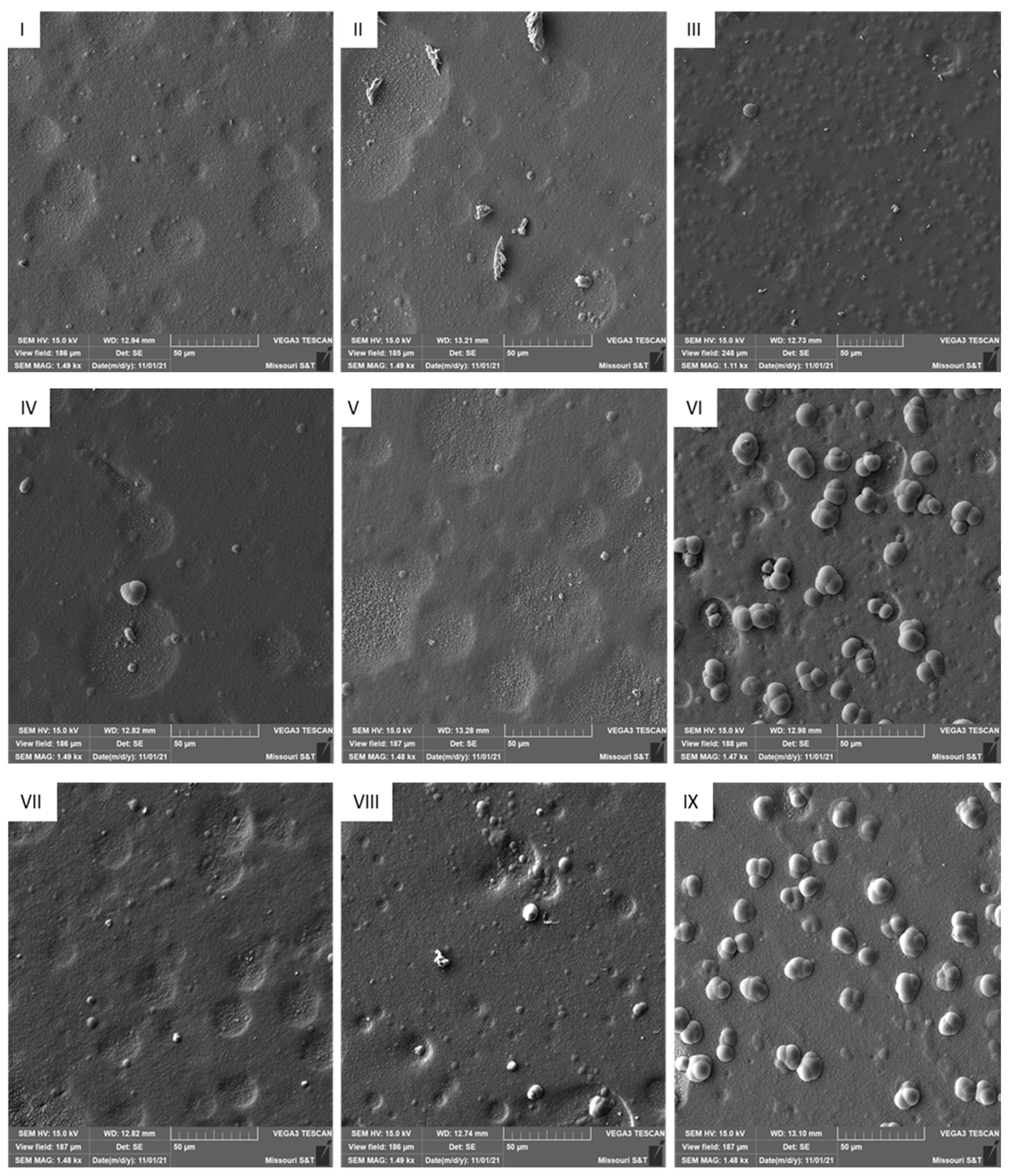
2.2. Zinc Coating Characterization

The surface morphology of the Hull cell deposits at the 320 A m−2 location was examined using TESCAN-ASCAT scanning electron microscopy (Tescan, Brno, Czechia) operated at 20 kV.
Deposit (215 to 325 A m−2 range on Hull cell cathode) brightness was measured using a BYK micro-TRI-gloss glossmeter (BYK, Wesel, Germany) at a measurement angle of 85°. Specular reflection occurs at the surfaces of reflecting objects, and this is attributed to glossiness [26].

2.3. Electrochemical Experiments

Electrochemical tests were performed in a three-electrode cell. A rotating 316 L stainless-steel working electrode disc (5 mm diameter), platinum mesh counter electrode, and mercury/mercury sulfate (MSE) reference electrode were used. The reference electrode was placed in a Luggin tube filled with the test solution. The tip of the Luggin tube was 1.5 cm from the surface of the working electrode. The working electrode was rotated at 500 rpm to minimize mass transport limitations. The solution was sparged with nitrogen gas for 10 min to remove oxygen before each experiment. The working electrode was pre-plated with zinc for 5 min using a current density of 320 A m−2. Then linear sweep voltammetry (LSV) was employed by scanning the working electrode potential from −1.9 to −2.2 V vs. MSE at a scan rate of 1 mV/s. The electrochemical tests were performed using a Gamry 3000 potentiostat (Gamry Instruments Inc, Warminster, PA, USA).

2.4. Current Efficiency (CE) and Throwing Power (TP)

A rectangular cell (7.2 cm × 15 cm) with a 1010 steel panel as the cathode and a mild steel mesh as the anode was used to measure current efficiency (CE). Zinc was electrodeposited for 15 min at a cathode current density of 305 A m−2. The cathodes were weighed before and after the experiment to obtain the mass of the deposit. The theoretical mass (m) was calculated using Faraday’s law, Equation (1):
m = I t M n F
where I is the current applied (A) for time t (s), n is the number of electrons involved in the reaction, M is the molar mass of zinc, and F is Faraday’s constant (96,485 C/mol). The percentage of the measured mass to the theoretical mass is CE.
A Haring–Blum cell [27] was used for the throwing power experiments. Throwing power (% TP) was calculated using Field’s formula [3], Equation (2):
% T P = L M L + M 2 × 100
where L is the ratio of the distance between the further and the nearer cathode (5:1) and M is the ratio of the mass of deposit on the nearer to further cathode.

3. Results and Discussion

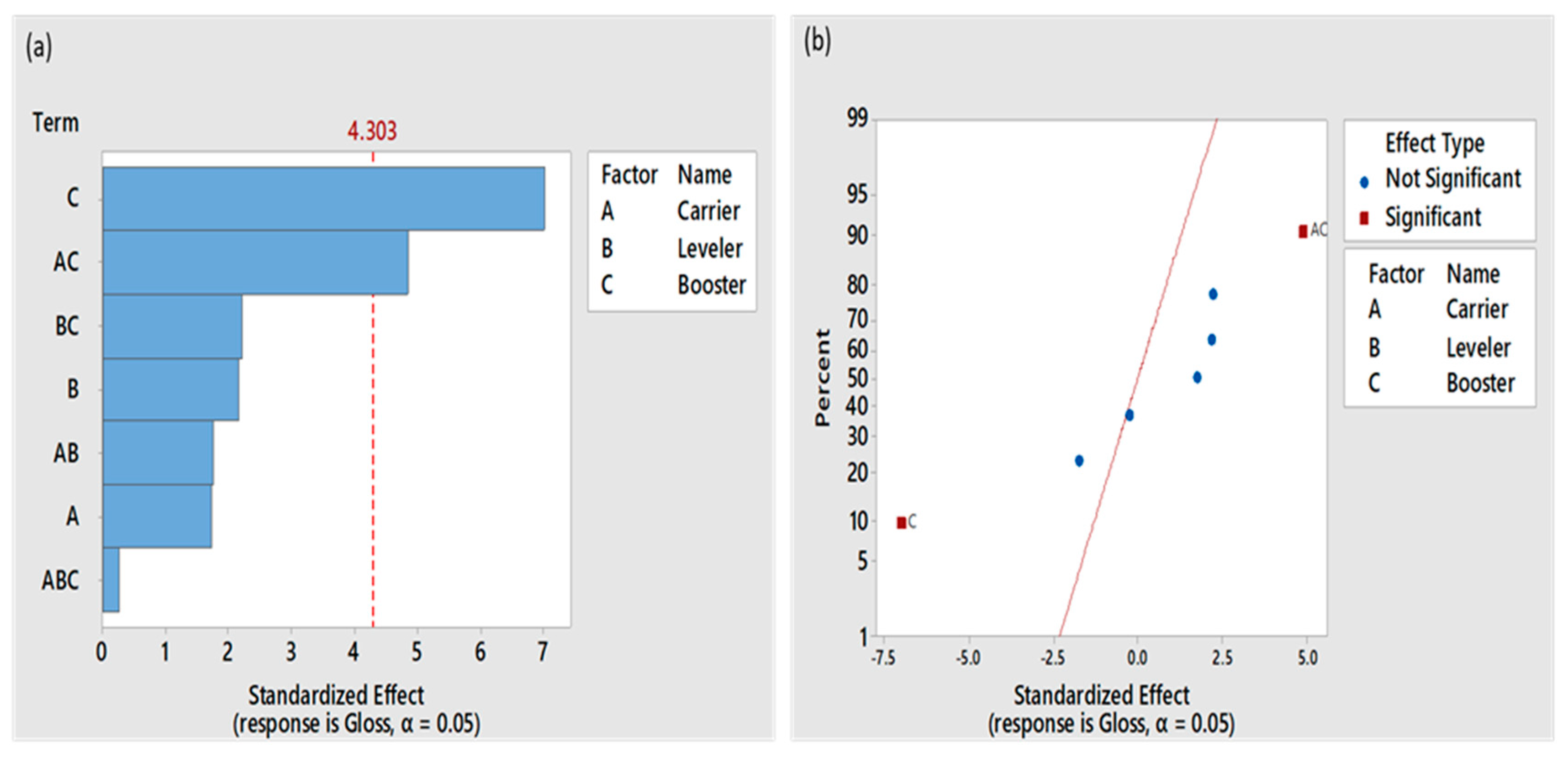
3.1. Deposit Appearance and Brightness

Preliminary Hull cell experiments were used to center our design of experiments. Plating baths with 1%, 2%, 3%, and 4% additive concentrations at a ratio of 5:2:1 (carrier/booster/leveller) [24] were examined. The visual appearance of the zinc deposits produced in these experiments is shown schematically in Figure 1. The 1% additive bath produced the widest range of current density with a bright appearance. Thus, 1% additive concentration was used as the center point for the 23 full factorial design of experiments to evaluate individual effects and interactions.
To observe the magnitude of the individual and synergistic effects of the additives on the zinc coating appearance and structure, Hull cell experiments were conducted with the additive concentrations shown in Table 1. The visual appearances of the Hull cell deposits are summarized in Figure 2.
As seen in Figure 2, current densities above 960 A m−2 resulted in burnt (or black) deposits for all baths, while gray deposits were observed at the low current density end except for bath III, which had a white streaky appearance at low current densities. Most of the baths produced bright deposits between ~50 and 325 A m−2 except baths III, VI, and IX. A bright deposit was produced by bath III from 215 to 750 Am−2. Baths VI and IX did not produce a bright deposit at any current density.
The average glossiness (brightness) of deposits in the current density range of 215 to 325 A m2 is reported in Table 2. This range was selected to represent industrially relevant conditions. Baths III and VI produced the brightest and least bright deposits, respectively.
An analysis of variance (ANOVA) was performed using Minitab software for a 23 factorial design with a center point with the gloss value as the output response. The magnitudes of the individual and synergistic effects of the additives were determined, and the ANOVA results are summarized in Figure 3. The standardized effects are tests of the null hypothesis that the effect is 0. The reference line indicates which effects are statistically significant at a significance level denoted by alpha (α = 0.005). Over the concentration ranges examined, booster concentration and the interaction between booster and carrier had a statistically significant effect on brightness as their standardized effects were greater than 4.303. Individually, carrier and leveller concentrations were not determined to be statistically significant on brightness.
The normal probability plot (shown in Figure 3b) shows the standardized effects relative to a distribution fit line for the case when all the effects are zero. The booster concentration shows a negative effect, hence a decreasing booster concentration enhanced brightness. The interaction between carrier and booster had a positive impact and resulted in greater brightness. Primary additives or carriers are typically added at higher concentrations compared with secondary additives or brighteners (booster). The carrier may serve as a hydrotrope to increase the solubility of the booster [28]. Therefore, increasing the carrier concentration with the proper amount of booster tended to enhance brightness. A proper carrier concentration ensures that the brightener (booster) is solubilized and stabilized [29].

3.2. Deposit Morphology

Figure 4 shows the surface morphology of deposits obtained from baths I to IX at 305 A m−2. Nodules or bumps were observed on the surface of coatings produced from baths VI and IX, which resulted in a rougher deposit with low gloss values. Deposits produced from the remaining baths exhibited circular depressions on their surfaces. These depressions are believed to be caused by hydrogen gas formation. The simultaneous evolution of hydrogen and reduction of zinc at the cathode resulted in depressions due to gas bubbles remaining on the zinc deposit. The growth of rougher zinc within the depressions is observed in several images in Figure 4. It is proposed that hydrogen evolution can lead to desorption of adsorbed additives, which in turn promotes the deposition of rougher zinc at those locations. Bath III had the least number of bumps and hydrogen evolution sites, which is believed to have caused the highest gloss value measured in this study.

3.3. Electrochemical Studies

Cathodic polarization studies were carried out to understand the effect of the additives on the zinc reduction process. Figure 5 illustrates the linear sweep voltammograms generated for each bath, including a bath without additives. The significant reduction in cathodic current densities as a function of electrode potential when additives were introduced to the plating bath is obvious and noteworthy.
The polarization curves produced with baths I to IX showed a gentle slope in reduction current (region E1), followed by a rapid increase in reduction current (region E2) with increasing potential. Other studies have attributed region E1 to the formation of an iron oxide/hydroxide [17,30] or zinc oxide/hydroxide [31,32] layer on the cathode. The former reason seems unlikely in this study due to the predeposition of zinc on the working electrode prior to the polarization scan. The latter reason also appears improbable as the bath without additives did not depict a similar behavior, respectively.
We believe region E1 was caused by the adsorption of additives on the cathode. The adsorbed additives inhibit the rate of zinc reduction, which allows for more compact deposits to form. This corresponds with results from the Hull cell plates, which showed bright deposits at lower current densities for most plating baths.
The transition from region E1 to E2 is believed to be related to the absorption strength of the additives on the zinc surface. Bath III (the brightest surface) has the most negative transitional potential, while baths VI and IX (the dullest surfaces) are the most positively shifted curves in region E2. These shifts in potential (or energy) reveal that the adsorption strength of the additives in the zincate baths with a more negative potential reveals a stronger bond and in turn the ability to produce smoother and brighter zinc surfaces.
The rapid increase in current observed in region E2 is believed to be caused by the desorption of additives due to hydrogen evolution [28]. The slope observed in the polarization curve of the additive free bath is similar to the slopes in region E2, which indicates that the possibility of the rate of zinc reduction is no longer being controlled by the plating additives in the region.

3.4. Throwing Power and Cathodic Current Efficiency

Throwing power (TP) as measured in a Haring–Blum cell and cathodic current efficiency (CE) were measured at 305 A m−2 (anodic current density for a Haring–Blum cell and cathodic current density for a two-electrode cell for CE). Average TP and CE values measured for the nine plating baths with additives (see Table 1) are presented in Table 3.
The baths exhibited high CE due to the high concentrations of Zn and NaOH. Higher sodium hydroxide concentration decreased the hydrogen ion activity, which resulted in high current efficiency. High zinc concentration increases the concentration of electroactive ion, which results in improvement in the efficiency of zinc deposition [22,33,34]. At 305 A m−2, the additives did not have any observable effect on CE.
An ANOVA of the throwing power results was performed with the findings presented graphically in Figure 6. The largest effect on throwing power was generated by the leveller concentration. While increasing the leveller concentration decreased the throwing power on average over the range studied, this effect was not statistically significant at α = 0.05. Throwing power has been found to depend on plating parameters, such as zinc concentration, pH, current density, temperature, and plating duration [35,36,37]; and other studies have shown that additives can improve throwing power in zincate baths [38]. However, over the concentration ranges examined for these specific additives, no correlation was made between throwing power and additive concentrations or interactions.

4. Conclusions

The effects and interactions of three commercial additives (Eldiem Carrier, Eldiem Booster, and Bright Enhancer 2×) in a strong zincate bath (Zn = 37.5 g L−1 and NaOH = 210 g L−1) on deposit brightness and morphology, cathodic polarization, throwing power, and current efficiency were examined at higher concentrations than previously reported in the literature. Analysis of Hull cell deposits showed a booster concentration, and the interaction between booster and carrier concentrations had significant effects on brightness within a current density range of 215 to 325 A m−2. Increasing the booster concentration from 0.63 mL/L to 1.88 mL/L resulted in an average decrease in the gloss value of the deposits produced. The decrease in brightness was mitigated by increasing the concentration of the carrier from 3.13 mL/L to 9.68 mL/L.
The concentrations of the additives had no statistically significant effect (at 95% confidence) on throwing power and current efficiency. Leveller concentration had the strongest effect on throwing power. Current efficiency at 305 A m−2 was 98%–99% for all conditions examined.
As expected, scanning electron microscopy revealed that rougher deposits correlated with duller (less gloss value) appearance. The presence of circular depressions indicates that hydrogen bubbles adhered to the zinc deposit during plating. Zinc nodules were commonly found in the circular depressions, indicating that hydrogen evolution may be disrupting the additives’ ability to produce smooth deposits.
Voltammetry indicated that additives significantly polarized the zinc deposition reaction. The potential at which additives desorb and/or hydrogen evolution commences appears to correlate with the presence of nodules on the zinc surface and thus deposit brightness on a qualitative basis.

Author Contributions

Methodology, formal analysis, investigation, writing—original draft preparation, A.J.M.; writing—review and editing, supervision, funding acquisition, M.M. All authors have read and agreed to the published version of the manuscript.

Funding

This research was funded by a public corporation who wishes to remain anonymous.

Institutional Review Board Statement

Not applicable.

Informed Consent Statement

Not applicable.

Data Availability Statement

Not applicable.

Conflicts of Interest

The authors declare no conflict of interest.

References

  1. Smith, W.J.; Goodwin, F.E. Hot dip coatings. In Reference Module in Materials Science and Materials Engineering; Elsevier: Amsterdam, The Netherlands, 2017. [Google Scholar]
  2. Dallin, G.W. Galvanizing-2015; Galvinfo Center—A Program of The International Zinc Association: Durham, NC, USA, 2015. [Google Scholar]
  3. Anchor Bolt and Construction Fastener Manufacturer. How Does Hot-Dip Galvanizing Differ from Electrogalvanizing? Available online: https://www.portlandbolt.com/technical/faqs/hot-dip-galvanizing-vs-electrogalvanizing-zinc-plating (accessed on 10 November 2021).
  4. Biddulph, C. Zinc electroplating. Prod. Finish. 2012, 1, 106. [Google Scholar]
  5. Vagramyan, T.; Leach, J.L.; Moon, J.R. The structures of zinc electrodeposits formed at low current densities. J. Mater. Sci. 1979, 14, 1170–1174. [Google Scholar] [CrossRef]
  6. Yuan, L.; Ding, Z.Y.; Liu, S.J.; Shu, W.F.; He, Y.N. Effects of additives on zinc electrodeposition from alkaline zincate solution. Trans. Nonferrous Met. Soc. China 2017, 27, 1656–1664. [Google Scholar] [CrossRef]
  7. Muralidhara, H.B.; Naik, Y.A.; Sachin, H.P.; Achary, G.; Venkatesha, T.V. A study on brightening and corrosive resistance property of electrodeposited zinc in non-cyanide alkaline bath. Indian J. Chem. Technol. 2008, 15, 259–265. [Google Scholar]
  8. Schlesinger, M.; Paunovic, M. Modern Electroplating; John Wiley & Sons: Hoboken, NJ, USA, 2014; pp. 423–452. [Google Scholar]
  9. Oniciu, L.; Mureşan, L. Some fundamental aspects of levelling and brightening in metal electrodeposition. J. Appl. Electrochem. 1991, 21, 565–574. [Google Scholar] [CrossRef]
  10. Tietcha, G.F.; Mears, L.L.; Dworschak, D.; Roth, M.; Kluppel, I.; Valtiner, M. Adsorption and diffusion moderated by polycationic polymers during electrodeposition of zinc. ACS Appl. Mater. Interfaces 2020, 12, 29928–29936. [Google Scholar] [CrossRef]
  11. Hope, G.A.; Brown, G.M.; Schweinsberg, D.P.; Shimizu, K.; Kobayashi, K. Observations of inclusions of polymeric additives in copper electrodeposits by transmission electron microscopy. J. Appl. Electrochem. 1995, 25, 890–894. [Google Scholar] [CrossRef]
  12. Geduld, H. Zincate or Alkaline Non-Cyanide Zinc Plating in “Zinc Plating”; ASM International Metals Park: Novelty, OH, USA, 1988; pp. 90–106. [Google Scholar]
  13. Ravindran, V.; Krishnan, R.M.; Muralidharan, V.S. Characteristics of an alkaline tartrate zinc plating bath. Met. Finish. 1998, 96, 10–15. [Google Scholar] [CrossRef]
  14. Crotty, D.; Bagnall, K. Analysis methods for zinc plating brighteners. Plat. Surf. Finish. 1988, 75, 52–56. [Google Scholar]
  15. Shanmugasigamani; Pushpavanam, M. Role of additives in bright zinc deposition from cyanide free alkaline baths. J. Appl. Electrochem. 2006, 36, 315–322. [Google Scholar] [CrossRef]
  16. Hsieh, J.C.; Hu, C.C.; Lee, T.C. Effects of polyamines on the deposition behavior and morphology of zinc electroplated at high-current densities in alkaline cyanide-free baths. Surf. Coat. Technol. 2009, 203, 3111–3115. [Google Scholar] [CrossRef]
  17. Ortiz-Aparicio, J.L.; Meas, Y.; Trejo, G.; Ortega, R.; Chapman, T.W.; Chainet, E. Effects of organic additives on zinc electrodeposition from alkaline electrolytes. J. Appl. Electrochem. 2013, 43, 289–300. [Google Scholar] [CrossRef]
  18. Naik, Y.A.; Venkatesha, T.V. A new brightener for zinc plating from non-cyanide alkaline bath. Indian J. Eng. Mater. Sci. 2003, 10, 318–323. [Google Scholar]
  19. Naik, Y.A.; Venkatesha, T.V. A new condensation product for zinc plating from non-cyanide alkaline bath. Bull. Mater. Sci. 2005, 28, 495–501. [Google Scholar] [CrossRef]
  20. Chotirach, M.; Rattanawaleedirojn, P.; Boonyongmaneerat, Y.; Chanajaree, R.; Schmid, K.; Metzner, M.; Rodthongkum, N. Systematic investigation of brightener’s effects on alkaline non-cyanide zinc electroplating using HPLC and molecular modeling. Mater. Chem. Phys. 2022, 277, 125567. [Google Scholar] [CrossRef]
  21. Pary, P.; Bengoa, J.F.; Conconi, M.S.; Bruno, S.; Zapponi, M.; Egli, W.A. Influence of organic additives on the behaviour of zinc electroplating from alkaline cyanide-free electrolyte. Trans. IMF 2017, 95, 83–89. [Google Scholar] [CrossRef]
  22. Wanotayan, T.; Kantichaimongkol, P.; Chobaomsup, V.; Sattawitchayapit, S.; Schmid, K.; Metzner, M.; Chookajorn, T.; Boonyongmaneerat, Y. Effects of chemical compositions on plating characteristics of alkaline non-cyanide electrogalvanized coatings. Nanomaterials 2020, 10, 2101. [Google Scholar] [CrossRef]
  23. Scott, M.; Moats, M. Optimizing additive ratios in alkaline zincate electrodeposition. In PbZn 2020: 9th International Symposium on Lead and Zinc Processing; Springer: Cham, Switzerland, 2020; pp. 123–131. [Google Scholar]
  24. Scott, M. Effect of Carriers, Brighteners, and Levelers on Zinc Electrogalvanizing in Alkaline Zincate Solutions. Master’s Thesis, Missouri University of Science and Technology, Rolla, MO, USA, 2020. [Google Scholar]
  25. Antony, J. Design of Experiments for Engineers and Scientists; Butterworth-Heinemann: Burlinton, UK; Oxford, MA, USA, 2003; pp. 60–65. [Google Scholar]
  26. Hunter, R.S. Methods of determining gloss. J. Res. Natl. Bur. Stand. 1937, 18, 958. [Google Scholar] [CrossRef]
  27. Gabe, D.R. Test cells for plating. Met. Finish. 2002, 100, 579–586. [Google Scholar] [CrossRef]
  28. Hsieh, J.C.; Hu, C.C.; Lee, T.C. The synergistic effects of additives on improving the electroplating of zinc under high current densities. J. Electrochem. Soc. 2008, 155, D675–D681. [Google Scholar] [CrossRef]
  29. Blakeley, A. Improving Acid Zinc Coverage and Brightness. Available online: https://www.pfonline.com/articles/plating-clinic-improving-acid-zinc-coverage-and-brightness (accessed on 16 November 2021).
  30. De Carvalho, M.F.; Rubin, W.; Carlos, I.A. Study of the influence of the polyalcohol mannitol on zinc electrodeposition from an alkaline bath. J. Appl. Electrochem. 2010, 40, 1625–1632. [Google Scholar] [CrossRef]
  31. Gomes, A.; da Silva Pereira, M.I. Pulsed electrodeposition of Zn in the presence of surfactants. Electrochim. Acta 2006, 51, 1342–1350. [Google Scholar] [CrossRef]
  32. Casanova, T.; Soto, F.; Eyraud, M.; Crousier, J. Hydrogen absorption during zinc plating on steel. Corros. Sci. 1997, 39, 529–537. [Google Scholar] [CrossRef]
  33. Ouakki, M.; El Fazazi, A.; Cherkaoui, M. Electrochemical deposition of zinc on mild steel. Mediterr. J. Chem. 2019, 8, 30–41. [Google Scholar] [CrossRef]
  34. Gamburg, Y.D.; Zangari, G. Theory and Practice of Metal Electrodeposition; Springer Science & Business Media: Berlin/Heidelberg, Germany, 2011; pp. 12–13. [Google Scholar]
  35. Ibrahim, M.A.M. Improving the throwing power of acidic zinc sulfate electroplating baths. J. Chem. Technol. Biotechnol. Int. Res. Process Environ. Clean Technol. 2000, 75, 745–755. [Google Scholar] [CrossRef]
  36. Sekar, R.; Jagadesh, K.K.; Ramesh Bapu, G.N.K. Role of amino acids on electrodeposition and characterisation of zinc from alkaline zincate solutions. Trans. IMF 2015, 93, 133–138. [Google Scholar] [CrossRef]
  37. Bapu, G.R.; Devaraj, G.; Ayyapparaj, J. Studies on non-cyanide alkaline zinc electrolytes. J. Solid State Electrochem. 1998, 3, 48–51. [Google Scholar] [CrossRef]
  38. Kavitha, B.; Santhosh, P.; Renukadevi, M.; Kalpana, A.; Shakkthivel, P.; Vasudevan, T. Role of organic additives on zinc plating. Surf. Coat. Technol. 2006, 201, 3438–3442. [Google Scholar] [CrossRef]
Figure 1. Hull cell deposit appearance produced from 1%, 2%, 3%, and 4% additive concentrations. Bath composition was 37.5 g L−1 zinc and 210 g L−1 NaOH held at 40 °C. A Hull cell ruler is presented at the top with current densities in A m−2.
Metals 12 00621 g001
Figure 2. Hull cell deposit appearances produced by plating baths with various additive concentrations (see Table 1). Bath composition was 37.5 g L−1 zinc and 210 g L−1 NaOH held at 40 °C. A Hull cell ruler is presented at the top with current densities in A m−2.
Metals 12 00621 g002
Figure 3. (a) Pareto chart and (b) Normal probability plot of the standardized effects of additives on gloss as determined by ANOVA with significant set at α < 0.05.
Metals 12 00621 g003
Figure 4. SEM images of Hull cell deposits at a current density of 305 A m−2. Labels correspond to baths I to IX in Table 1. SE mode was used due to the topographical nature caused by the nodules.
Metals 12 00621 g004
Figure 5. Cathodic polarization of plating baths with 37.5 g L−1 zinc and 210 g L−1 NaOH at 40 °C produced at a sweep rate of 1 mV s−1. Bath additive concentrations are provided in Table 1.
Metals 12 00621 g005
Figure 6. (a) Pareto chart and (b) normal probability plot of the standardized effects of additives on throwing power.
Metals 12 00621 g006
Table 1. Additive concentrations of baths used in this study.
BathCarrier (mL/L)Leveller (mL/L)Booster (mL/L)
I6.252.501.25
II9.383.750.63
III3.133.750.63
IV9.383.751.88
V9.381.251.88
VI3.131.251.88
VII9.381.250.63
VIII3.131.250.63
IX3.133.751.88
Table 2. Average gloss values of Hull cell deposits produced between 215 and 325 A m−2.
BathGloss
I71
II70
III85
IV70
V62
VI35
VII75
VIII80
IX55
Table 3. Throwing power and cathodic current efficiency for the plating baths with additive concentrations provided in Table 1 with a current density of 305 A m−2 at the anode in the Haring–Blum cell (throwing power) and the cathode in the two-electrode cell (current efficiency). Base electrolyte conditions were 37.5 g L−1 Zn and 210 g L−1 NaOH at 40 °C.
BathThrowing Power (%)Current Efficiency (%)
I2399
II2499
III1899
IV3099
V3798
VI2998
VII3298
VIII3099
IX2198
Publisher’s Note: MDPI stays neutral with regard to jurisdictional claims in published maps and institutional affiliations.

