Article

Influence of Cell Opening Methods on Electrolyte Removal during Processing in Lithium-Ion Battery Recycling

by
Denis Manuel Werner
1,2,*,
Thomas Mütze
3 and
Urs Alexander Peuker
1
1
Institute of Mechanical Process Engineering and Mineral Processing, TU Bergakademie Freiberg, Agricolastraße 1, 09599 Freiberg, Germany
2
LIBREC AG, Fabrikstraße 4, 4562 Biberist, Switzerland
3
Processing Department, Helmholtz-Zentrum Dresden-Rossendorf (HZDR), Helmholtz Institute Freiberg for Resource Technology (HIF), Chemnitzer Str. 40, 09599 Freiberg, Germany
*
Author to whom correspondence should be addressed.
Metals 2022, 12(4), 663; https://doi.org/10.3390/met12040663
Submission received: 19 February 2022 / Revised: 31 March 2022 / Accepted: 2 April 2022 / Published: 13 April 2022
(This article belongs to the Special Issue Processing and Characterization of Metal Containing Wastes)

Abstract

:
Lithium-ion batteries (LIBs) are an important pillar for the sustainable transition of the mobility and energy storage sector. LIBs are complex devices for which waste management must incorporate different recycling technologies to produce high-quality secondary (raw) materials at high recycling efficiencies (RE). This contribution to LIB recycling investigated the influence of different pretreatment strategies on the subsequent processing. The experimental study combined different dismantling depths and depollution temperatures with subsequent crushing and thermal drying. Therein, the removal of organic solvent is quantified during liberation and separation. This allows to evaluate the safety of cell opening according to the initial depollution status. These process steps play a key role in the recycling of LIBs when using the low-temperature route. Therefore, combinations of pretreatment and processing steps regarding technical and economic feasibility are discussed. Moreover, the process medium and equipment properties for a safe cell opening, the technical recycling efficiencies and their consequences on future industrial LIB waste management are pointed out.

1. Introduction

Lithium-ion batteries (LIBs) have significantly higher energy and power densities than conventional batteries and accelerated the introduction of stationary and portable energy storage devices as well as electric mobility in particular. Besides the positive effects like compensating current peaks and emission-free vehicles, LIBs exert additional pressure on the natural resources demanding an efficient and sustainable waste management scheme. Moreover, they consist of several critical raw materials as defined by the European Commission in terms of reliability and sustainability [1] like Co, Li, and natural graphite and also of toxic and hazardous ones. Co is intended to be reduced or even totally substituted in terms of mass share in cathode coatings, whereas Li and natural graphite will remain substantial elements [2,3].
Therefore, recycling regarding closed-loop material recovery is an indispensable technological necessity to meet the demands for raw materials in battery production [4]. Additionally, LIB recycling avoids environmental and health risks, which arise from the hazardous substances like transition metals and electrolyte components. Hence, recycling is prescribed by national legislation to become independent from global geostrategic as well as processing impacts, to reduce supply chain risks, to enhance social and environmental standards and to boost the recycling economy [5,6,7,8]. Consequently, the mass-based recycling efficiency (RE) is supplemented by material recovery rates (MRR) in two periods (2025 and 2030) within the upcoming European battery regulation. Therein, the RE will be increased for the total battery mass to 65% (2025) and 70% (2030). MRR will be introduced for Li, Ni, Co and Mn. Especially WEEE, waste (electrical) vehicles and other battery-containing equipment will be considered as waste-generating applications further on. For those applications, European law stipulates a recovery rate of 75%. For small WEEE like small IT and telecommunication devices, reuse and a RE of 55% have to be realized. End-of-life vehicles have to apply for reuse, recovery rate of 95% and a RE of 85%.
The present study evaluated solvent evaporation using different methods for LIB cell opening to propose an overall disposal strategy for current and upcoming LIB applications, designs, and compositions. The methods are combined with thermal drying to determine and compare quantitatively the overall solvent evaporation. Recently, the evaporation of manually opened cells to different dismantling depths, which were subsequently treated thermally, was investigated [9]. In the present article, the mass balance of liberation and separation is analysed for non-depolluted mechanically opened LIB cells. Furthermore, thermally treated cells and higher dismantling depths are further processed. As a result, the amount of gases released are compared for the respective procedures. Consequently, potential pretreatment strategies for LIB depollution and safe cell opening are discussed. Moreover, their recyclability is roughly estimated with respect to the investigated LIB cell and related to the three main industrial routes for LIB recycling.

2. Recycling of Spent LIBs

A comprehensive overview of the recycling of end-of-life (EOL) LIBs can be found in Werner et al. [9] as well as in Werner et al. [10]. Here, additional details are summarized focusing on crushing and thermal drying on an industrial scale.

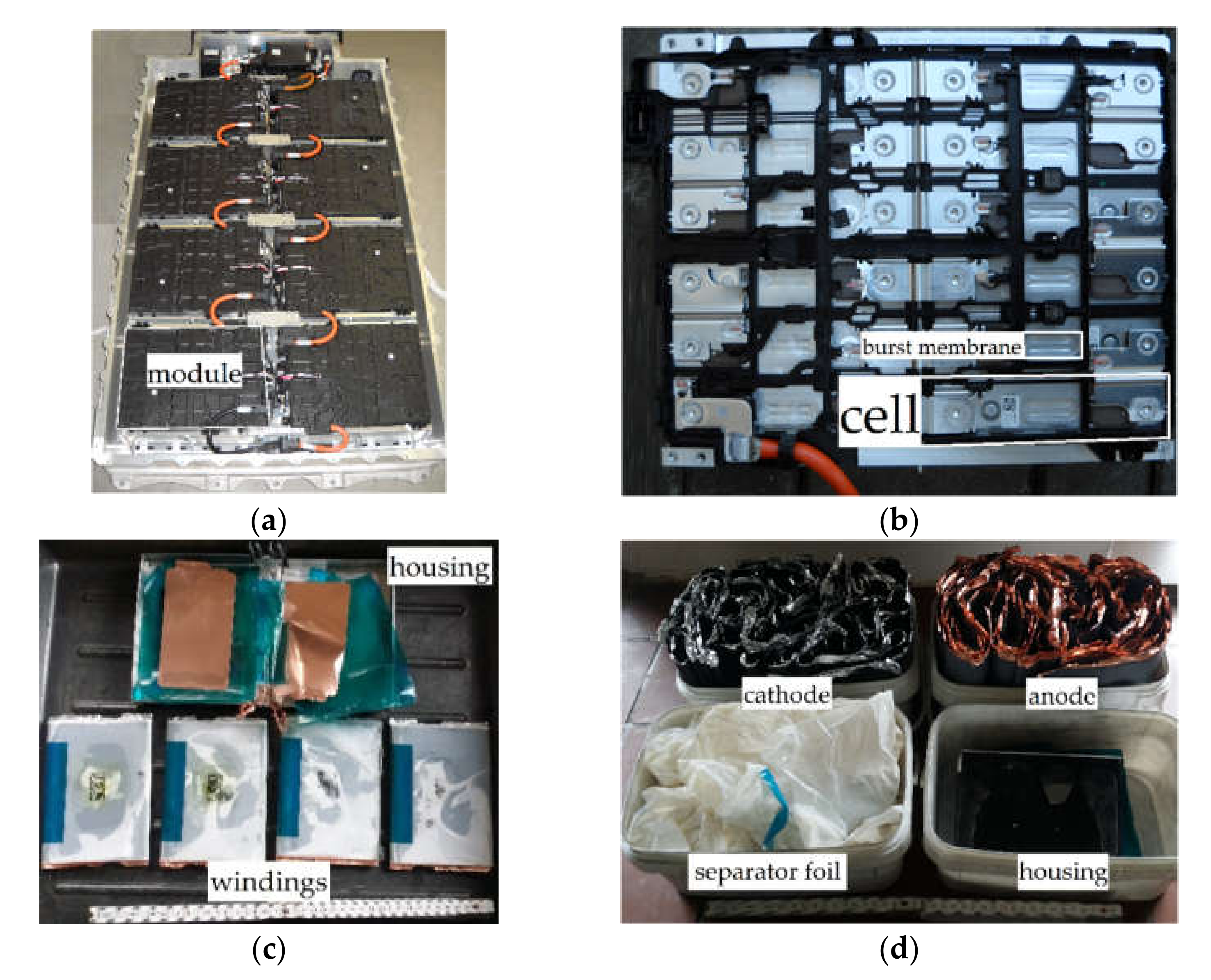
2.1. Design and Hazards of LIBs

LIB consist in a principle of two electrodes, a separator and an electrolyte forming an assembly which is defined as functional unit. The electrodes are layered composite of active materials (AM) coated on metallic current collector foils. On the anode side (negative electrode), graphite or amorphous carbon are commonly used as AM. The positive electrode (cathode) is based on Li-alloyed materials like transition metal oxides as single or mixed-metal oxide or metal phosphate with differences in their structural design. Ni, Co, Al and/or manganese (Mn) alone or with different stoichiometry are applied for the metal oxides on the one hand, and iron phosphate on the other hand, respectively [11]. Together with binder and additives, these AMs are coated on both sides of an Al foil on the cathode side and of a Cu foil on the anode side. The separator, a porous plastic foil, prevents direct contact of the electrodes. The pores of electrode coatings and separator foil are filled with an ion-conducting electrolyte, which is a high-purity multi-component system. It consists of a mix of organic solvents like ethylene carbonate (EC), dimethyl carbonate (DMC), ethyl methyl carbonate (EMC), and diethyl carbonate (DEC), Li hexafluorophosphate (LiPF6) as conductive salt and further additives. The selection and concentration of additives is always custom-made. Moreover, the electrolyte–electrode–layer ratio is oriented on specification profiles of the LIB and cell designs of the manufacturers [12,13].
The functional unit is formed to stacks, round or flat jelly rolls determining the cylindrical, prismatic and blade-hard case cell types or the soft case pouch cell type [12,13,14,15]. Together, the functional unit and the hermetic housing form a battery cell. The cell is enclosed by metal-based housing and packaging materials, which differ in thickness and design properties. The cells can be connected in series or parallel to form either a single block or a module as a subunit of a larger battery system [10,15,16]. Additional peripheral components like a battery management system, cooling, electronic and electric parts on a cell, module or system level complete a LIB. On the one hand, the used materials differ for battery functional components, cells, modules, or systems [13]. On the other hand, LIB systems vary in applied battery cell types, number of battery cells, connections, as well as dimensions and mass, thus in their material composition [8,13,15,17,18,19,20,21,22,23,24,25]. Hence, EOL LIBs are considered as a highly complex waste with increasing complexity from the functional unit to the battery system.
Potential hazards arise from LIBs’ voltage, state of charge and specific components, which are hazardous and reactive under special conditions [10,26,27,28]. For example, the components of the electrolyte require special care, as the organic solvents can cause fire and explosion [18,29] and their hygroscopicity facilitates corrosion [20]. In addition, the conductive salt has a limited chemical and thermal stability, which potentially leads to further flammable and toxic gases. As a result, fire and various chemical reactions can happen before, during and after battery cell opening with respect to the initial depollution status [12,30].

2.2. Waste Management of EOL LIBs

LIB disposal, its planning and process design face a huge challenge and require a high flexibility due to its great inhomogeneity in structure and composition as well as the problematic ingredients [15,31]. However, the main objective of recycling is to close the material cycle by generating secondary (raw) materials for the original or a different application [32,33]. Particularly, the RE of a process was established in the recycling efficiency ordinance (EU) 493/2012 by relating the cumulative mass of recovered secondary (raw) materials (output fractions) to the mass of batteries fed into the process (input fractions) [34]. The characteristic value RE, which is process-oriented, corresponds to the material-oriented recyclability proposed by Pomberger [35], who additionally differs between theoretical, technical, and real recyclability. Moreover, MRR for specific elements (Co, Ni, Li and Cu), as well as a recycled content of Li, Co, and Ni to produce new industrial, electric vehicle and automotive batteries, is defined in the upcoming battery regulation.
In general, the material transformation from EOL LIBs to secondary (raw) materials follows the recycling chain in four process stages with two-unit processes each [10,36]. The temperature during depollution categorizes the industrial recycling technologies for EOL LIBs into three main processing routes (low, medium and high temperature). The temperature limit between low- and medium-temperature routes is set at around 120 °C to enable the recovery of most of the contained materials, especially the organic solvents and plastics. The temperature limit between the medium- and high-temperature route can be set at the upper working range of pyrolysis at approximately 600 °C.
Each route differs in the effort for preparation, pretreatment and processing and thus the technical recyclability [10]. Therein, the low-temperature route achieves the highest RE due to preservation of the organic components. Moreover, it can be assumed that with increasing temperatures applied in the respective process route, the overall energy consumption rises simultaneously. However, no adequate data or comparative studies are currently available to support this. Anyway, especially the low-temperature route must deal with the strategies for safe material processing of LIBs including the process medium and procedures for handling, dismantling and liberation.

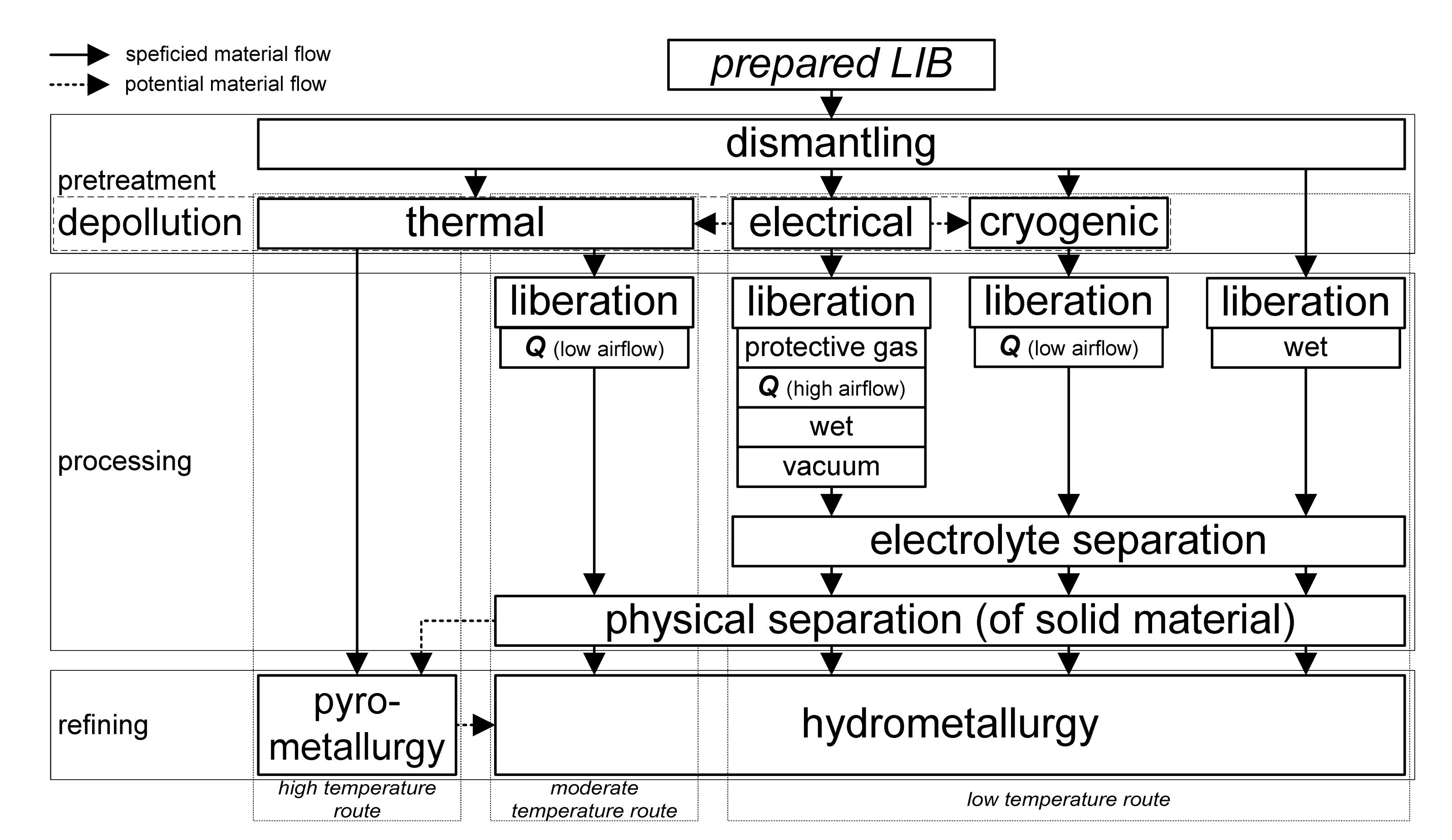
2.3. Processing of EOL LIBs

Processing of EOL LIBs follows the process steps preparation (waste logistics and presorting) and pretreatment (dismantling and depollution), and includes liberation and separation by mechanical, thermal or chemical methods [10]. This contribution focuses only on mechanical liberation and thermal separation. Mechanical liberation aims to break up the bonds between the individual components or even materials to enable physical separation of the generated bulk material into defined material concentrates [37]. Moreover, it also conditions the size or surface of particles to influence the adaptability and efficiency of subsequent separation technologies [38,39]. The goal of thermal separation in particular is to separate the organic solvents and their decomposition products by evaporation.

2.3.1. Mechanical Cell Opening

Opening LIB cell housings enables separation of the individual components or materials of the functional unit. It can be done either as dismantling during pretreatment or as liberation during processing. However, it is an optimisation problem between the costs of dismantling on the one hand and further mechanical and/or metallurgical processing on the other [15,40,41,42]. The methods for cell opening can be distinguished into manual, automatic and mechanical ones [9].
Mechanical cell opening is mainly achieved by crushing using stress modes for materials with ductile material behaviour [28,37,43]. Rotary shears or shredders apply shear or tearing stress, respectively, to open the metal housing of the LIB [18,44,45]. Crushing LIB systems or modules is usually performed in two stages [46,47], occasionally in one [25,29,48]. In contrast, LIB cells are crushed mostly in one stage due to their smaller size and lower breakage strength with regard to the available crushing technology [49]. In two-staged crushing setups, the initial pre-crushing can be interpreted as a conditioning step, creating fragments which fit perfectly into the subsequent final crusher. The main task of the final crushing is to fully liberate the individual components (cathode, anode, separator and housing) or even individual materials (e.g., current collector foils and AMs of the electrodes) of the battery [50,51].

2.3.2. Process Medium for Mechanical Cell Opening

LIB recycling in terms of processing is challenged by the batteries’ hazard potential, their design for a safe battery cell opening and the respective depollution strategy [10,15]. The design of a safe cell opening as well as the choice of a suitable process medium depend on the properties of the input material [20]. In general, the complexity of mechanical cell opening increases with lower dismantling depth. Consequently, an increased stress intensity is required affecting the design of the process and equipment for crushing. Moreover, corrosive and heat resistant materials are recommended to protect the tools and process chambers of the used equipment if the organic solvents are still active [49]. Remaining intercalated Li in the anode and/or flammable electrolyte components can cause adverse events and reactions due to uncontrolled cell opening [14,45].
Therefore, a sophisticated pretreatment strategy in terms of dismantling and depollution methods and adequate choice of process medium prevent the rise of temperature, fire, and consequently chemical reactions, or explosive condition (cf. Figure 1) [9,52]. Ideally, the battery cells are electrically depolluted (corr. discharged) before cell opening, or even before dismantling to cell level with respect to transport and work safety [25,41]. Thermal and cryogenic depollution, on the one hand, follow discharging, or on the other hand, stand-alone [53].
The use of the process medium for liberation depends on the depollution process and strategy. In principle, dry and wet process media can be distinguished to minimize the hazard potentials of LIBs during cell opening [9,54]. Wet medium includes water and brines such as salt solutions [55,56]. Dry process medium clusters several protective gases and ambient air. The latter varies in terms of volumetric airflow. In this context, low volumetric airflow represents a standard dedusting setup, whereas a high airflow is used to avoid the explosion limits by a strong dilution of the solvents [18]. Nevertheless, no limit is defined to distinguish low and high volumetric airflow so far. In addition, new concepts create a vacuum in the shredding chamber.
Cells which are thermally or cryogenically depolluted with or without discharging enable a safe cell opening in all process media. However, no special precautions must be taken, thus ambient air at low airflow (corr. to common dedusting) is applied. In contrast, if the cells were only discharged, cell opening should be conducted only under protective gas, and high airflow, or in vacuum and wet media. Recently, processes have also become known that dispense with the expensive and time-consuming depollution step. For this purpose, water is primarily used as the medium for cell disruption, whereby there is no information on possible exothermic reactions, the formation of hydrofluoric acid (HF) as well as the further handling of the contaminated process water. The gases or dusts that are produced after cell opening are absorbed in the process medium used. Especially the organic solvents, which are still active after electrical, cryogenic or no depollution, must be separated from the solid components after crushing.

2.3.3. Handling of the Process Medium after Crushing

Regardless of the process medium, volatile electrolyte fumes and dust must be separated from the process medium by using adequate purification systems. Here, discontinuous dry crushing under an inert atmosphere or vacuum seems to be more favourable from the economical, ecological and safety perspective [3,45]. Reasons are especially the high amount of wastewater that must be cleaned during or after wet crushing, and the high energy consumption of a thermal or cryogenic process for depollution. The process safety and economy remain critical for continuous crushing under low or high aerial flows with respect to compliance with explosion protection limits and the solvents containing off-gas treatment.
Regarding process design and control, processes using protective atmosphere or vacuum run only discontinuously to regulate the conditions in the crushing chamber, whereas aerial or wet conditions allow discontinuous and continuous processes. With respect to hazardous, non-depolluted electrolyte components, dismantling depth and battery cell size as well as the corresponding gas emissions during cell opening determine the choice and amount of process medium. Furthermore, the process medium influences the overall operating and technological costs.

2.3.4. Electrolyte Removal

Battery fragments or crushed materials, which are still loaded with electrolyte, have an environmental impact, and require further safety measures, like gas-tight and explosion-protected equipment. Therefore, partial or complete removal of the electrolyte components is mandatory and improves the subsequent separation regarding dry material handling and theoretical recyclability. Several methods for the recovery of electrolyte solvents and the conducting salt were investigated within the research project LithoRec [20] and at the ReCell Center [43]. However, removal of the electrolyte solvents and a high amount of the conducting salt is also possible via thermal drying (corr. evaporation). Drying can be achieved by high temperature, low pressure and/or rinsing with protective gas. Dunagan and Ostrander [57] initially neutralized a crushing product in liquid medium followed by a drying step. By comparing the examined methods, thermal drying shows advantages with respect to auxiliary materials, energy and equipment, process design and throughput.
The depollution strategy affects processing aspects like choice of process medium, requirements of safety equipment, energy demand, and selection of the subsequent separation processes as well as the theoretical RE of the process route [10]. In addition to the metallic components of the battery cell, plastics, solvents, and graphite must be recovered on their material base to maximize RE; even graphite, for example, currently accounts as a reducing agent. Consequently, the low-temperature route, where LIBs are only discharged as depollution, achieves the highest theoretical RE [15,20,46]. Potential process chains include, on the one hand, manual or mechanical cell opening under air with prior solvent extraction or, on the other hand, cell opening under protective atmosphere and subsequent solvent separation.

3. Materials and Methods

Two methods for cell opening in combination with one method for a subsequent separation of the organic solvents were examined and compared. The emphasis is put on the comparison of the cell liberation by manual dismantling and mechanical liberation via crushing as well as its implications onto subsequent solvent separation by thermal drying. The temperatures for drying have been selected below 150 °C to avoid the decomposition of plastics and electrolyte components. The high boiling solvents (e.g., PC, EC) are usually not evaporated completely at these temperatures [9]. The decomposition of the conductive salt rises with increasing temperatures activating the generation of hydrofluoric acid (HF) in adverse conditions [58]. As a result, the influence of dismantling depth and thermal depollution on solvent release during, as well as after, comminution can be determined quantitatively.

3.1. Materials

An automotive prismatic cell (Samsung SDI, Yongin-si, South Korea; capacity: 94 Ah; charging voltage: 3.68 V; cell mass: 2038.4 g; 172 mm × 125 mm × 45 mm) was used for the experiments due to its state-of-the-art status and its high electrolyte content compared to other cell types [59]. The cells were taken from an automotive battery system consisting of 8 modules and respective 12 prismatic cells. Each cell contained 4 windings as functional unit. The battery system was not used in an electric vehicle but subjected to charge and discharge cycles. Hence, it is assumed that all cells have suffered the same working conditions, and thus, show a similar state of health. Table 1 shows the material composition of a battery cell. The quantitative composition of the functional unit´s components and the housing are easy to determine by manual dismantling and material separation after manual cell opening. However, for the electrolyte components, only qualitative data and the overall share for the solvents are available. As the amount of solvents was determined by vacuum drying, conductive salt and additives remain in theory within the pores of the functional unit´s components. The bursting membrane shows a rectangular shape with 36 mm × 12 mm.

3.2. Test Equipment

Complex and multistep experiments in laboratory and semi-industrial scale with respect to equipment and machines were employed, combining liberation and separation of the recycling chain for EOL LIBs (cf. Figure 2) [10]. The dismantling of a battery system to module and cell level was carried out via manual disassembling, using several tools to liberate the different components. Depollution in terms of electrical discharging was performed before cell dismantling with an electrical resistance. The organic solvents were removed via thermal drying in a laboratory fume at room temperature (ca. 22 °C) or in laboratory drying chambers under ambient atmosphere. Three temperatures (22 °C, 80 °C and 120 °C) and two drying times (1 h, 120 h) were applied. A detailed description procedure for pretreatment regarding manual dismantling and thermal depollution are described in Werner et al. [9].
Two different semi-industrial machines were employed for liberation [18,44,50]. On the one hand, pre-crushing was carried out in a slow-rotating, two-shafts machine with a divided crushing chamber (cf. Figure 3a), which is a self-built machine by the Institute for Mechanical Process Engineering and Mineral Processing (Freiberg, Germany). The shafts show 20 mm (rotary ripper: RR) or no (rotary shear: RS) axial gap between the 40 mm crushing tools, which are shaped punctiform or linear, respectively. Hence, the stress modes for the experiments are a combined shear and tear stress for the first pre-crushing and mere shear for the secondary pre-crushing. On the other hand, the final crushing was conducted by a fast rotating, one shaft rotary shear (or cutting mill; MeWa Andritz Universal Granulator UG 300; Hechingen, Germany) with an exchangeable outlet grid (round opening sizes: 10, 20, 30, 40 mm; cf. Figure 3b). The design of all crushing steps has been linked to the particular feed material.
The in- and output mass was determined for each setup. Each material (cell, cell fragments or components) was crushed individually with simultaneous dedusting by a mobile industrial dedusting system (RUWAG DS2, Melle, Germany) above the feed of the crushing machines. The dedusting system included an activated carbon filter to reduce the impact of released gases from cell opening with respect to work and environmental safety. No dedusting was applied directly at the commination chamber of the crushing machines. Thermal drying at one (80 °C) or two different temperatures (22 °C, 80 °C) represents the separation of organic solvents with respect to feed material. The equipment consisted of a laboratory fume and a drying chamber. The mass of the crushing products was determined after 1 h and 120 h. Three cells were investigated for each depollution and drying temperature of the respective liberation step. Thus, in total, 63 cells were used for the experiments.

3.3. Methods

One crucial shortcoming is the unknown amount of organic solvents in the cells and their actual chemical composition. Since the cell manufacturers keep this information secret due to intellectual properties, an alternative approach is therefore to measure the evaporated mass as quantitative measure of gases (organic solvents), which was released during different processing steps. Hence, the mass balance for mechanical cell opening and thermal drying has been analysed. The mass difference between input and output materials mi and mo originates on the one hand to solid components of the battery, which have been removed by dismantling. On the other hand, it results from gases, which are generated by the evaporation of organic solvents or their decomposition products, or dust during crushing. The amount of dust or chips generated during dismantling was negligible small (<0.01%). Thus, the relative mass difference Δw is determined by the generated mass difference related to the initial cell mass.
Δw = (mimo)/mcell
Additionally, the relative amount of gases wos was calculated for each of the process steps p (dismantling (1), depollution (2), liberation (3), and separation (4)). It results from the cumulative mass difference of each process step related to the overall mass difference. In principle, it quantifies the contribution of each process step to the overall evaporation.
w os = p = 1 4   ( m i , p m o , p ) / ( m i m o )
The overall degree of liberation A is calculated for the LIB cells´ solid parts as the ratio of liberated solid materials compared to the total amount of the origin compound (i.e., cell mass) [50], which is adopted by Schubert´s degree of liberation for a single material or component j [60].
Aj = mlib,j /mtot,j
Finally, the throughput was determined with respect to input mass mi and respective work time t required for the respective process step. Dismantling covers the process steps from “system” to “electrodes” (cf. Figure 2). Mechanical liberation is performed in three stages: first precrushing (RR), second precrushing (RS) and final crushing (UG with different sizes of the discharge grid in mm). The residence time in the machines tr corresponds with the work time.
= mi/t

4. Results and Discussion

At first, the initial manual cell opening and depollution, the liberation of whole battery cells or the crushing of individual cell components and the final drying are shown for each unit process, one after the other, based on the intermediate products of the respective previous unit process. After that, a general process chain is presented linking the results of the manual cell opening with thermal depollution [9] and the present ones.

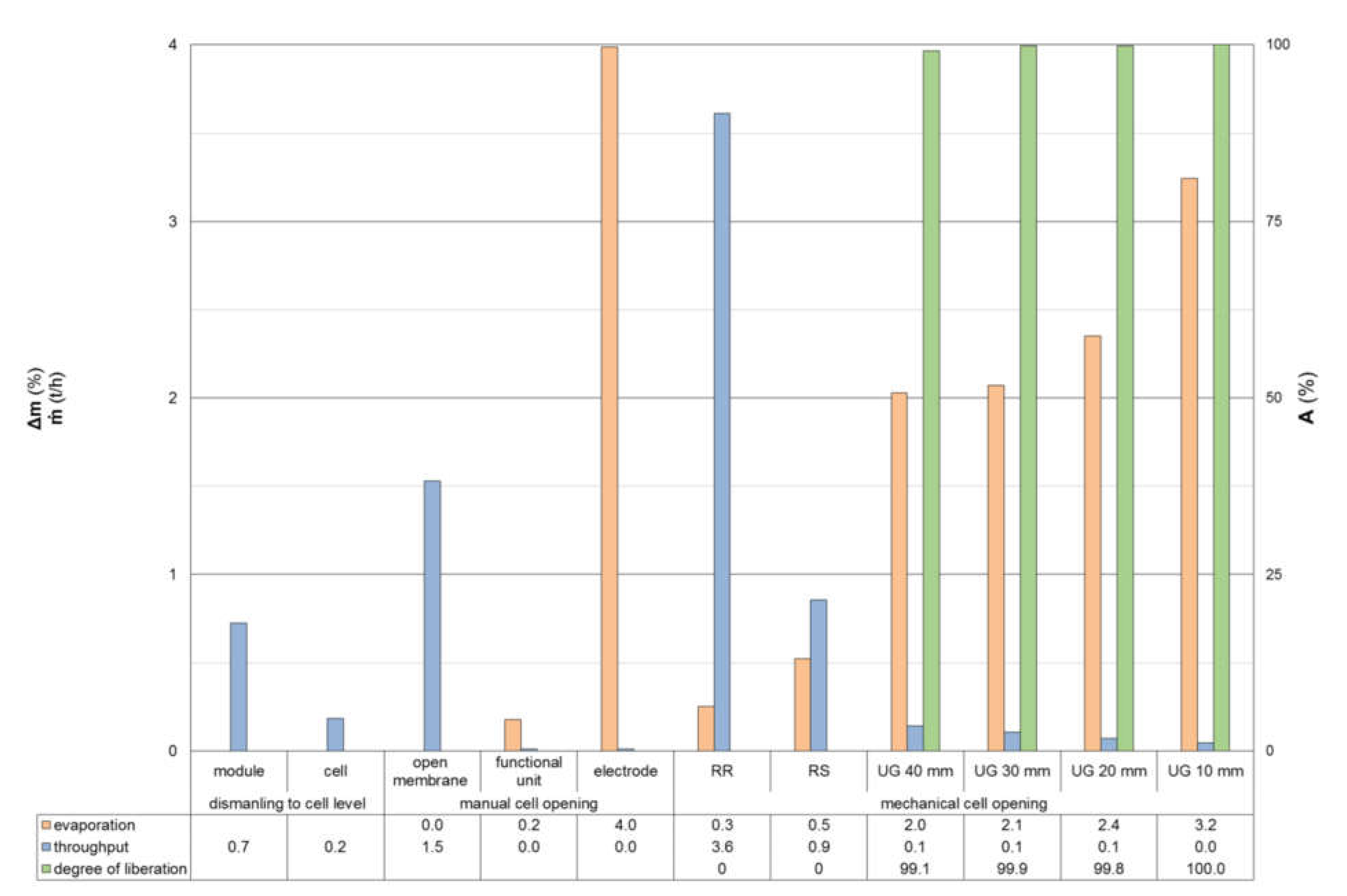
4.1. Manual and Mechanical Cell Opening

After manual dismantling from battery system to cell level, further manual cell opening to electrode level (cf. Figure 4) was compared to mechanical cell opening. In either case, the mass of the material remaining to be processed is decreasing with each process step due to the removal of solid components (dismantling to cell level) or the evaporation of organic solvents (manual and mechanical cell opening; cf. Figure 5). The solid components consist of parts like system and module housing, battery management system, thermal regulation system, electronics, electrical cables and connectors. Components and assembly groups must be disassembled individually and successively with increasing dismantling depth, leading to a higher number of handling steps and a longer process time.
In principle, the evaporation of solvents increases with higher dismantling depth, as well as with decreasing shredding particle size, e.g., due to decreasing gap or outlet grid sizes of crushing equipment. As soon as the functional unit is partially or completely liberated, more gases are generated due to a larger free and thus active surface area for evaporation. The composition of organic solvents contained in LIBs’ electrolyte are varying. Nevertheless, especially low boiling solvents are emitted initially [52], which pose explosion potential. Therefore, throughput of the respective cell opening step must comply with the explosion limits inside the comminution chamber to provide safe operation conditions. Hence, the process medium and its solvent loading capacity must be adjusted to the crushing conditions.

4.2. Liberation of Pretreated Materials

After manual cell opening and thermal depollution for 120 h and at 22 °C, 80 °C or 120 °C, individual materials generated during dismantling were liberated with the respective combination of crushing steps (1st and 2nd precrushing and/or final crushing at 30 mm discharge grid opening size, cf. Figure 2). Figure 6 shows the cumulative relative mass difference after 120 h thermal depollution (pretreatment), precrushing and/or final crushing for the respective dismantling depths and depollution temperatures [9]. Therein, the relative mass difference during pretreatment for the components housing and winding on the one side, as well as anode and cathode on the other side, are equal (orange shaded columns for pretreatment in Figure 6).
The reason for this equality lies in the procedure of manual cell opening and the mass difference between the dismantling steps of functional unit and electrodes, respectively. During crushing, further mass differences are observed for the respective components (dark colour for pretreatment in Figure 6). Only the mass differences generated during the crushing of windings is considered as pure gas release. The differences for housing, cathode and anode are attributed to gas as well as dust generation due to delamination of finest particles originating from the AMs during drying and subsequent crushing of the electrodes. A differentiation between evaporation of gas and dust emission was not possible due to the air exhaust system, which removed both of them simultaneously for safety reasons. However, the amount of dust is below 0.1% of the total mass difference, and therefore negligible.
Crushing the housing has no influence on gas release, independently of the depollution temperatures. Measurement fluctuations lead already to relatively high mass differences due to the comparatively low feed mass. In contrast to this, crushing the electrodes, in particular anodes, shows a significant mass difference, which increases for anodes with higher depollution temperature. For cathodes, the mass difference remains on a constant level. Besides further gas release, the coating material of the electrodes is partly liberated from the current collector foils by the applied shearing stress.
In general, anodes´ coating shows lower adhesive forces compared to the one from the cathode. This effect promotes selective decoating of the electrodes [50], which is further influenced by temperature [61]. Thus, very fine particles occur, which either are partially released from the crushing chamber or settle in niches or inaccessible areas of the chamber. However, the share of particles in the relative mass difference cannot be determined with the experimental set-up used, although this must increase, since the volatile solvents would have to be separated at 80 °C and 120 °C after 120 h.
In contrast, the relative mass difference of cells with open-burst membrane as well as the winding for the respective crushing step results from the evaporation of the respective components´ remaining solvents. In principle, the relative mass difference during final crushing decreases with higher depollution temperatures. Furthermore, the final crushing step shows a higher gas release than the precrushing due to an achieved higher degree of liberation, larger free and consequently active surface area of all components. The release of gases during crushing of cells with open-burst membrane, which were depolluted at 22 °C, fits to the crushing results of cells without pretreatment.

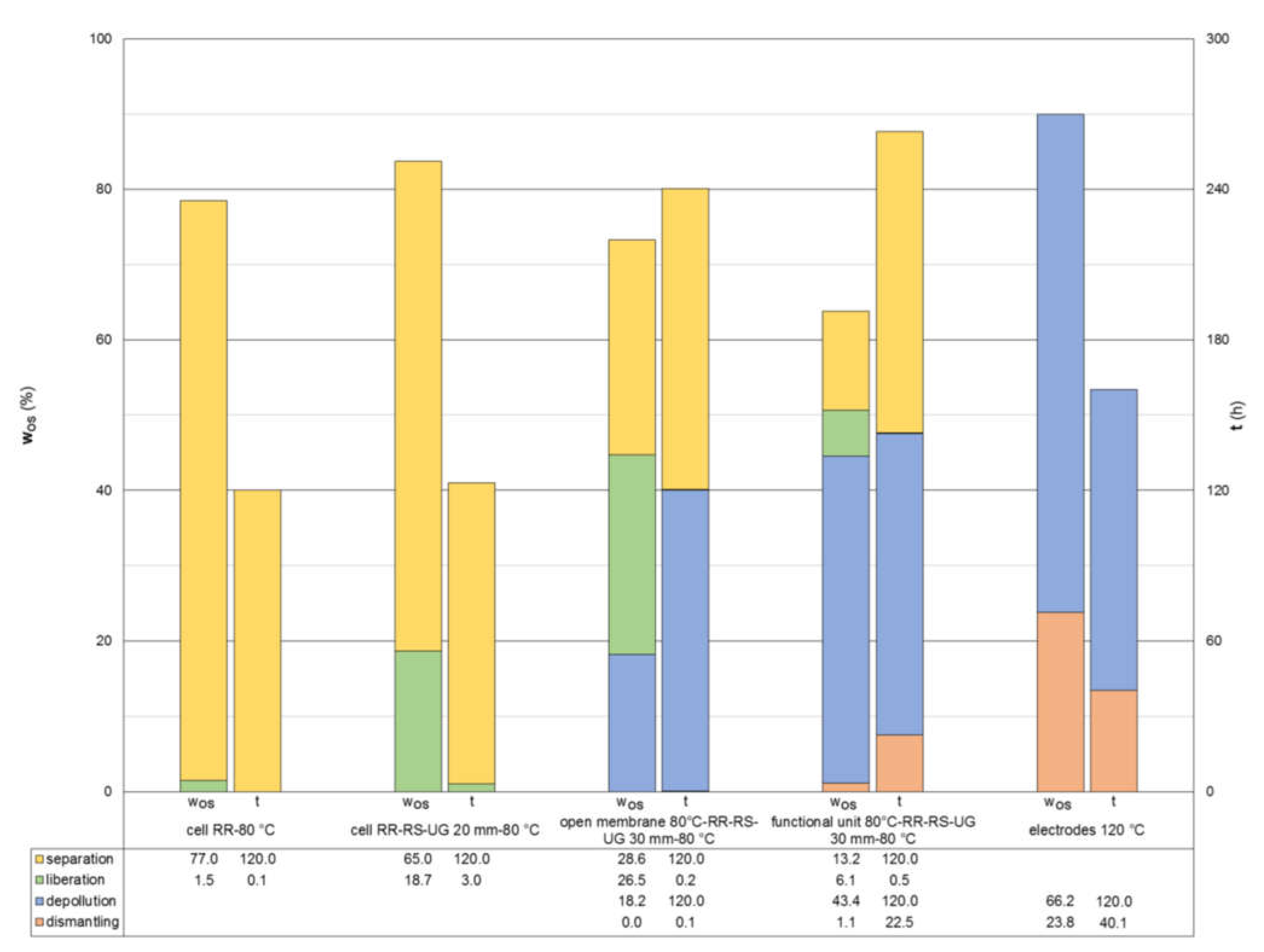
4.3. Thermal Drying of Crushing Products

The crushing products generated from different pretreatment and cell opening methods were dried at 22 °C or 80 °C for at least one hour up to 120 h. The results are shown in Figure 7 regarding the dismantling depth, depollution temperature and the equipment of the last crushing step. The solvent evaporation reaches around 12% at 80 °C for most of the cases, which is around 3% lower compared to the case of dismantling cells to electrode level due to a limited heat and mass transfer in bulk materials than in vertically arranged electrodes [9]. The crushing shows the logic trend that a higher liberation and specific surface due to a more intense stressing (RR → RS → UG) improves the release of gases. Also, gas generation via drying of the crushing products increases with higher temperatures, but not according to the degree of liberation and higher particle surface, as expected for the test series with different grid sizes (UG: 40 to 10 mm).
The particle properties influence obviously the heat and mass transfer during the stationary convective drying. The partly liberated cell fragments after first and second precrushing show a slightly open lamella structure due to the manufacturing process of the functional unit, which either stacks or rolls the components separator, cathode and anode to an electrode winding [12]. In contrast, the product of the final crushing in UG is always a bulk material with differences in particle size distribution and degree of decoating due to different energy input. Depolluted cells and fragments show higher gas release after mechanical cell opening within the first hour of drying in comparison to non-depolluted cells and fragments. The prior gas release within pretreatment, which results in less amount of solvents, in particular in the pore volume of the functional unit´s components, reduces the material´s heat capacity, and consequently fasten heat and mass exchange enhancing evaporation.
One important result is that a minimum of 80 °C is required under ambient conditions to remove the main part of the solvents. Separation is only incomplete at ambient temperatures, e.g., 22 °C, leaving about a quarter to half of the electrolyte in the battery materials. A thermal treatment at 120 °C also removes a large part of the solvents but changes the adhesive forces of the coating materials at the current collector foils [61], decomposes the separator foil and might lead to instability of the conductive salt, which together negatively influences subsequent separation processes.

4.4. Potential Process Chains

Various process chains regarding the release of organic solvents before and after cell opening are conceivable due to results presented in the chapters above and in [9]. Selected variants are pointed out in more detail regarding process time as well as possible solvent removal. Figure 8 presents the results of relative solvent reduction and process time for three variants with pretreatment and two without. The two-stage processes of mechanical cell opening, and subsequent drying, show a significant time advantage with high solvent evaporation. This time advantage can be translated into a high throughput of the corresponding technical processes. The variants with manual cell opening and thermal depollution, subsequent crushing as well as drying achieve a slightly higher solvent evaporation, but require a longer process time, and therefore require bigger equipment. In comparison, complete disassembly of a battery cell to electrode level achieves the highest solvent evaporation at a comparable process time. One advantage of solvent removal at the electrodes level is that it can be done at 120 °C since the thermal stability of the separator is not a problem anymore. Nonetheless, this process chain cannot be easily scaled up to bigger throughputs due to an at least ten-times-longer interval for manual dismantling compared to the easily scalable mechanical cell opening.
Manual disassembly of battery cells to a functional unit or even electrodes level is time, i.e., manual work labour consuming, and must address several safety issues. Nevertheless, it is a very effective preparation to remove the organic solvents, especially from a scientific perspective in the very common case of an unknown battery cell composition. In addition, a clean housing fraction can be produced simultaneously. The required process medium depends on the tools and their working principles for cell opening. Additionally, dismantling to the electrode level enables sorting of the functional unit’s components. However, it is economically unfeasible in industrial applications; even automated disassembly could increase the profitability and challenge mechanical processing [62,63]. Unfortunately, the high variety of LIB batteries, their complexity in designs and material compositions are the big challenge there.
Thermal depollution of battery cells with burst membrane supersedes electrical depollution theoretically. For this, battery cells with an openable bursting membrane are required calling for a specific pre-sorting step. Unfortunately, merely temperature-driven thermal depollution is economically unfeasible in industrial applications. Consequently, only pyrolysis and calcination remove adequately all the solvents from EOL LIB, which, in turn, results in the total loss of solvents for material recycling, reducing the theoretical RE of the corresponding medium- and high-temperature route [33,64]. Crushing under protective atmosphere would be one alternative for battery cells without or with closed-burst membrane. In that case, the electrical hazard source must be deactivated completely prior to cell opening.
The combination of precrushing in a slow-rotating machine and subsequent drying shows very low solvent evaporation during crushing and a high one during drying. In theory, the precrushed battery cells can be dried before further liberation. Hence, no protective measures are necessary for final crushing, only prior discharging, and off-gas treatment. However, the fragments after precrushing present low bulk material characteristics, which influence the design of material transportation and handling for the drying process [65].
The combination of several crushing steps down to 10 mm and subsequent drying necessitates protective gas or liquids during crushing for safety reasons. The number of crushers needed can be reduced in industrial applications due to higher reduction ratios in industrial crushers compared to laboratory equipment. Thereby, the process time might be decreased but the consumption of process medium will increase, too. The drying kinetic itself can be optimized with higher temperature or lower pressure [20]. Several options of drying equipment are existing for the generated bulk materials [65], like vacuum shovel dryers [52].

4.5. Recycling Efficiencies of the Process Routes

The presented variants (cf. Figure 8) with and without thermal depollution can be considered as a part of the low-temperature route, respectively. The low-temperature route is theoretically and technically able to recover the electrolyte´s organic solvents. Moreover, the additives, binder and conductive salt contained in the electrodes and electrolyte are added to the RE. Hence, the applied temperatures avoid the decomposition of the materials contained in a LIB cell. Thus, 100 mass percent RE is theoretically achievable, but only at high financial and technological expenditure, which might be outweighed by the environmental benefits [66].
In contrast, the medium-temperature route uses higher temperatures for depollution. However, applying pyrolysis or thermolysis, at least the cathodes´ Al foil tend to corrode. Moreover, the organic materials (plastics and others, solvents) are used as process heat, are transferred into pyrolytic oil [47], or, together with the conductive salt, binder and additives, are decomposed [3,67], which depends on the process conditions of pyrolysis or thermolysis [64,68]. Hence, under the worst conditions, the theoretical RE reaches around 65–70 mass percent for the investigated LIB cell [69].
In comparison to that, the focus of the high temperature route is put on the Ni, Co, Cu, steel and electronic parts. Graphite, carbon black and the plastics are used as reducing agents, or are burned [15,23]. Other components like binder, additives or solvents from the electrodes and electrolyte are used energetically within the process [34,67]. Al, which is also used as a reducing agent, as well as Mn and Li are slagged [15,33,67]. Even the slag fraction fulfils the legal requirements by using it as construction material, and it is claimed that Li can be recovered hydrometallurgically from the slag [34,70]; these materials do not contribute to a closed material loop, thus theoretical RE is around 30 mass percentage for the used LIB cell [69].
In principle, the RE in technical processes lies below the theoretical and technical RE due to dissipative losses and separation inefficiencies during the overall waste treatment [35]. For example, only the plastics polypropylene and polyethylene are materially recycled, whereas others are commonly recovered thermally by incineration. The components separator and housing contain small amounts of these materials (cf. Table 1). However, they are usually not recycled due to their non-tradable shape, quality and layered composite structure. In addition, the electrodes´ binder, the conductive salt and additives of the electrodes and electrolyte are also not recovered due to low intrinsic value and amount in the battery as well as lack of competitiveness against primary materials.
Furthermore, the role of the oxygen contained in the cathode coating, which makes up around 10% of the examined battery cell, is controversially discussed [34]. The material recycling of oxygen contained in cathode coating is technically proven for a closed battery-to-battery loop [67,71]. However, this technological, ecological, and economical interesting approach might not be feasible for EOL batteries due the continuous development of battery technology and the time gap to disposal [72]. Nevertheless, cathode coating recycling is an option for production wastes [15,43].
Hence, oxygen of EOL batteries either ends up in the slag or gas fraction of the high temperature route or is released during the hydrometallurgical treatment. A detailed stoichiometric calculation for the respective process is required to determine the actual amount of recyclable oxygen. Thus, the respective real RE might be changed, i.e., reduced tremendously due to the holistic view and inclusion of market economy principles in particular. If the decided legal framework towards material recovery rates comes into effect, the substitution of Co increases, and the proportion of cells and coatings in the battery system continues to rise, the high temperature route will become obsolete.

5. Conclusions

Different combinations of pretreatment and processing methods are investigated regarding the removal of organic solvents from a representative prismatic automotive LIB. Therefore, battery cells and components that had been manually opened and dismantled down to electrode level were examined. The crushing tests of the generated materials were performed with a combination of slow- and fast-rotating rotary rippers and shears. The selection of the combination was adapted to the dismantling depth. Drying temperatures of up to 80 °C were used for organic solvent removal of the crushed materials.
The thermal depollution of cells through their burst membrane shows no satisfying results in terms of removeable amount of solvents for the investigated depollution temperatures between 22 °C and 120 °C and a drying time of 120 h at ambient pressure. Consequently, the removal of organic solvent during or after cell opening is imperative for process design at these temperatures. It is necessary to depollute the crusher atmosphere as well as the crushing product to enable a subsequent safe and efficient (dry) material separation. The removal of evaporated solvents demands the installation of safety measures in terms of explosion prevention and fire protection to enhance work safety.
The solvent content of batteries can be derived from manual cell opening for dimensioning the process medium. Manual cell opening might be an option for research purposes simplifying further processing. Nevertheless, manual opening is a very time-consuming, and thus costly, process compared to mechanical cell opening [43]. Both methods represent an area of conflict between the advantages of a high dismantling depth and a multi-step liberation and separation. Higher dismantling depths enable the creation of (almost) pure components or material fractions and the reduction of crushing steps and the number of the subsequent mechanical or physical separation processes. In contrast, multi-step liberation and separation achieve higher throughputs and require lower manpower, since automated dismantling still requires several years of development work before it can be used on an industrial scale. However, the evaporation of solvents is in the same order of magnitude comparing the dismantling to electrodes level and mechanical cell opening with a rotary shear like the universal granulator UG.
As a result, the removed organic solvents are assigned mostly to the low boiling components (light volatiles) of the electrolyte. The remaining electrolyte components consist of especially high boiling components (heavy volatiles) as well as the conductive salt depending on the drying process (temperature, pressure, etc.). Dry separation is possible for the material with remaining heavy volatiles and conductive salt. Corrosion-resistant wall lining is recommended for all surfaces in contact with the material. The remaining electrolyte components are contained in the AMs which are usually separated as black mass.
A pure temperature-driven drying process is inefficient regarding a time and material recovery perspective. The evaporation can be enhanced by lower air pressures to increase the process kinetics below 1 h. For this, detailed investigations on optimal drying equipment, parameters and efficiency of solvent removal are necessary. On peculiar focus would have to be the characterization of evaporation and decomposition of the individual electrolyte components.
The choice of the process medium (air, inert gas, water, etc.) depends on the used depollution temperature and throughput. Further influences derive from the cell housing (deformation and breakage behaviour of the material, wall thickness, outer dimensions of cell, design features), the amount and composition of the organic solvents, and the stress mode and intensity of the crushing devices. The complexity of the task and hazardous risks increase with further battery or module components. Consequently, the depollution strategy in terms of organic solvent and remaining electrical energy removal is decisive for the design, economy, energy consumption and RE of the recycling chain.
Worldwide, several industrial recycling technologies provide secondary (raw) materials for new battery applications or other products. The ongoing and dynamic development of battery types and chemistries results in shifting business cases and process interfaces. In addition to changes in the legal framework, energy consumption and the release of climate-damaging substances will also have to be considered in the future. Here, too, the application of the low-temperature route is becoming increasingly important. Enhancing this, electrical depollution and dismantling remains time-, space- and personnel-intensive, as well as logistically complex and challenging [53,73].

Author Contributions

Conceptualization, methodology, investigation, and writing—original draft preparation, D.M.W. and T.M.; writing—review and editing, D.M.W., T.M. and U.A.P.; supervision, T.M. and U.A.P.; project administration, U.A.P.; funding acquisition, U.A.P. All authors have read and agreed to the published version of the manuscript.

Funding

This research was funded by the Federal Ministry for Education and Research (BMBF), as well as the Projektträger Jülich (PTJ), Innovative Recyclingprozesse für neue Lithium-Zellgenerationen-Mechanische Prozesse (InnoRec) 03XP0246C within the Competence cluster for battery cell production (ProZell).

Institutional Review Board Statement

Not applicable.

Informed Consent Statement

Not applicable.

Data Availability Statement

Data sharing is not applicable.

Acknowledgments

The authors would gratefully like to acknowledge the BMW AG that provided materials and information for the experimental part. The authors would also like to thank the technical and scientific staff of the Institute of Mechanical Process Engineering and Mineral Processing for making the equipment used for the experimental part available, as well as our reviewers for their thorough review of the manuscript and detailed feedback.

Conflicts of Interest

The authors declare no conflict of interest.

Nomenclature

AMActive materials
AlAluminium
CMCSodium Carboxymethyl Cellulose
CoCobalt
CuCopper
DECDiethyl carbonate
DMCDimethyl carbonate
EOLEnd-of-life
ECEthylene carbonate
EMCEthyl methyl carbonate
HFHydrofluoric acid
LiLithium
LiPF6Lithium hexafluorophosphate
LIB(s)Lithium-ion battery(ies)
MRRMaterial recovery rates
MnManganese
NMCLithium nickel manganese cobalt battery
NSDNail Penetration Safety Device
PCPropylene carbonates
PETPolyethylene terephthalate
PPPolypropylene
PVDFPolyvinylidene fluoride
RERecycling efficiency
RRSlow-rotating, two-shafts rotary shear with axial gap
RSSlow-rotating, two-shafts rotary shear without axial gap
SBRStyrene butadiene rubber
UGOne shaft rotary shear with outlet grid) final crushing

References

  1. Babbitt, C.; Althaf, S.; Cruz Rios, F.; Bilec, M.M.; Graedel, T.E. The role of design in circular economy solutions for critical materials. Perspective 2021, 4, 353–362. [Google Scholar] [CrossRef]
  2. Hanisch, C.; Haselrieder, W.; Kwade, A. Recycling von Lithium-Ionen-Batterien–das Projekt LithoRec. In Recycling und Rohstoffe; Thomé-Kozmienski, K.J., Goldmann, D., Eds.; TK Verlag: Neuruppin, Germany, 2012; Volume 5, pp. 691–698. [Google Scholar]
  3. Vezzini, A. Manufacturers, Materials and Recycling Technologies. In Lithium-Ion Batteries Advances and Applications; Pistoia, G., Ed.; Elsevier: Amsterdam, The Netherlands, 2014; pp. 529–551. [Google Scholar]
  4. Baars, J.; Domenech, T.; Bleischwitz, R.; Melin, H.E.; Heidrich, O. Circular economy strategies for electric vehicle batteries reduce reliance on raw materials. Nat. Sustain. 2021, 4, 71–79. [Google Scholar] [CrossRef]
  5. Rothermel, S.; Winter, M.; Nowak, S. Background. In Recycling of Lithium-Ion Batteries-The LithoRec Way; Kwade, A., Diekmann, J., Eds.; Springer: New York, NY, USA, 2018; pp. 1–31. [Google Scholar]
  6. Pinegar, H.; Smith, Y.R. Recycling of End-of-Life Lithium Ion Batteries, Part I: Commercial Processes. J. Sustain. Metall. 2019, 5, 402–416. [Google Scholar] [CrossRef]
  7. Harper, G.; Sommerville, R.; Kendrick, E.; Driscoll, L.; Slater, P.; Stolkin, R.; Walton, A.; Christensen, P.; Heidrich, O.; Lambert, S.; et al. Recycling lithium-ion batteries from electric vehicles. Nature 2019, 575, 75–86. [Google Scholar] [CrossRef] [Green Version]
  8. Mossali, E.; Picone, N.; Gentilini, L.; Rodrìguez, O.; Perez, J.M.; Colledani, M. Lithium-ion batteries towards circular economy: A literature review of opportunities and issues of recycling treatments. J. Environ. Manag. 2020, 264, 110500. [Google Scholar] [CrossRef]
  9. Werner, D.; Mütze, T.; Peuker, U.A. Influence of cell opening methods on organic solvent removal during pretreatment in lithium-ion battery recycling. Waste Manag. Res. 2021, 10, 316. [Google Scholar] [CrossRef]
  10. Werner, D.; Peuker, U.A.; Mütze, T. Recycling Chain for Spent Lithium-Ion Batteries. Met. Open Access Metall. J. 2020, 10, 316. [Google Scholar] [CrossRef] [Green Version]
  11. Zhao, S.; He, W.; Li, G. Recycling Technology and Principle of Spent Lithium-Ion Battery. In Recycling of Spent Lithium-Ion Batteries-Processing Methods and Environmental Impacts; An, L., Ed.; Springer Nature Switzerland AG: Cham, Switzerland, 2019; pp. 1–26. [Google Scholar]
  12. Korthauer, R. Lithium-Ion Batteries: Basics and Applications; Korthauer, R., Ed.; Springer GmbH: Berlin, Germany, 2019. [Google Scholar]
  13. Kwade, A.; Haselrieder, W.; Leithoff, R.; Modlinger, A.; Dietrich, F.; Droeder, K. Current status and challenges for automotive battery production technologies. Nat. Energy 2018, 3, 290–300. [Google Scholar] [CrossRef]
  14. Liu, B.; Jia, Y.; Yuan, C.; Wang, L.; Gao, X.; Yin, S.; Xu, J. Safety Issues and Mechanisms of Lithium-ion Battery Cell Upon Mechanical Abusive Loading: A Review. Energy Storage Mater. 2019, 24, 85–112. [Google Scholar] [CrossRef]
  15. Thompson, D.L.; Hartley, J.M.; Lambert, S.M.; Shiref, M.; Harper, G.D.J.; Kendrick, E.; Anderson, P.; Ryder, K.S.; Gaines, L.; Abbott, A.P. The importance of design in lithium ion battery recycling—A critical review. Green Chem. 2020, 22, 7585–7603. [Google Scholar] [CrossRef]
  16. Korthauer, R. Handbuch Lithium-Ionen-Batterien; Korthauer, R., Ed.; Springer Vieweg: Berlin/Heidelberg, Germany, 2013. [Google Scholar]
  17. Chen, M.; Ma, X.; Chen, B.; Arsenault, R.; Karlson, P.; Simon, N.; Wang, Y. Recycling End-of-Life Electric Vehicle Lithium-Ion Batteries. Joule 2019, 3, 2622–2646. [Google Scholar] [CrossRef]
  18. Wuschke, L. Mechanische Aufbereitung von Lithium-Ionen-Batteriezellen. Ph.D. Thesis, TU Bergakademie Freiberg, Freiberg, Germany, 2018. [Google Scholar]
  19. Weyhe, R. Verbundprojekt ”Rückgewinnung der Rohstoffe aus Li-Ion Akkumulatoren“; Accurec GmbH: Mühlheim, Germany, 2008. [Google Scholar]
  20. Kwade, A.; Diekmann, J. Recycling of Lithium-Ion Batteries-The LithoRec Way; Kwade, A., Diekmann, J., Eds.; Springer: New York, NY, USA, 2018. [Google Scholar]
  21. Arnberger, A.; Gresslehner, K.-H.; Pomberger, R.; Curtis, A. Recycling von Lithium Ionen Batterien aus EVs & HEVs. In Proceedings of the DepoTech 2012, Leoben, Austria, 6 November 2012. [Google Scholar]
  22. Gaines, L.; Sullivan, J.; Burnham, A. Life-Cycle Analysis for Lithium-Ion Battery Production and Recycling. In Proceedings of the 90th Annual Meeting of the Transportation Research Board, Washington, DC, USA, 23–27 January 2011. [Google Scholar]
  23. Georgi-Maschler, T.; Friedrich, B.; Weyhe, R.; Heegn, H.; Rutzc, M. Development of a recycling process for Li-ion batteries. J. Power Sources 2012, 207, 173–182. [Google Scholar] [CrossRef]
  24. Wang, X.; Gaustad, G.; Babbitt, C.W. Targeting high value metals in lithium-ion battery recycling via shredding and size-based separation. Waste Manag. 2016, 51, 204–213. [Google Scholar] [CrossRef] [PubMed] [Green Version]
  25. Arnberger, A.; Coskun, E.; Rutrecht, B. Recycling von Lithium-Ionen-Batterien. In Recycling und Rohstoffe; Thomé-Kozmiensky, K.J., Goldmann, D., Eds.; TK Verlag Karl Thomé-Kozmiensky: Neuruppin, Germany, 2018; Volume 11, pp. 583–599. [Google Scholar]
  26. Rahimzei, E. Begleit-und Wirkungsforschung Schaufenster Elektromobilität (BuW) Ergebnispapier Nr. 37-Sicherheit von Elektrofahrzeugen; Deutsches Dialog Institut GmbH: Frankfurt am Main, Germany, 2017. [Google Scholar]
  27. Elwert, T.; Römer, F.; Schneider, K.; Hua, Q.; Buchert, M. Recycling of Batteries from Electric Vehicles. In Behaviour of Lithium-Ion Batteries in Electric Vehicles-Battery Health, Performance, Safety, and Cost; Pistoia, G., Liaw, B., Eds.; Springer International Publishing AG: Cham, Switzerland, 2018. [Google Scholar]
  28. Gama, M. European Li-Ion Battery Advanced Manufacturing for Electric Vehicles-ELIBAMA. Available online: https://cordis.europa.eu/project/id/285385 (accessed on 19 February 2022).
  29. Hanisch, C.; Diekmann, J.; Stieger, A.; Haselrieder, W.; Kwade, A. Recycling of Lithium-Ion Batteries. In Handbook of Clean Energy Systems; Yan, J., Cabeza, L.F., Sioshansi, R., Eds.; John Wiley & Sons, Ltd.: Hoboken, NJ, USA, 2015; Volume 5, pp. 2865–2888. [Google Scholar]
  30. Van Pels, W. Herausforderung hinsichtlich der Brandschutztechnologien in Recyclinganlagen insbesondere bei der Verarbeitung von Li-Ionen Traktionsbatterien. In Proceedings of the Recycling und Sekundärrohstoffe, Berlin, Germany, 2–3 March 2020; pp. 496–505. [Google Scholar]
  31. Wegener, K.; Andrew, S.; Raatz, A.; Dröder, K.; Herrmann, C. Disassembly of Electric Vehicle Batteries Using the Example of the Audi Q5 Hybrid System. In Proceedings of the Conference on Assembly Technologies and Systems, Dresden, Germany, 15–16 May 2014. [Google Scholar]
  32. Ritthoff, M. Recycling und Ressourcenschonung stoffliche Aspekte der Kreislaufwirtschaft. In NABU-DSD-Dialogforum Kreislaufwirtschaft; Wuppertal Institut: Berlin, Germany, 2016. [Google Scholar]
  33. Sojka, T.R. Sichere Aufbereitung von Lithium-basierten Batterien durch thermische Konditionierung. In Proceedings of the Recycling und Sekundärrohstoffe, Berlin, Germany, 2–3 March 2020; pp. 506–523. [Google Scholar]
  34. Tytgat, J. The Recycling Efficiency of Li-ion EV batteries according to the European Commission Regulation, and the relation with the End-of-Life Vehicles Directive recycling rate. In Proceedings of the International Battery, Hybrid and Fuel Cell Electric Vehicle Symposium, Barcelona, Spain, 17–20 November 2013. [Google Scholar]
  35. Pomberger, R. Über theoretische und reale Recyclingfähigkeit. Österr Wasser Und Abfallw 2020, 319, 12. [Google Scholar] [CrossRef]
  36. Martens, H.; Goldmann, G. Recyclingtechnik; Martens, H., Goldmann, G., Eds.; Springer Vieweg: Wiesbaden, Germany, 2016. [Google Scholar]
  37. Schubert, G. Comminution Equipment for Non-Brittle Waste and Scrap. Aufbereitungstechnik 2002, 43, 6–23. [Google Scholar]
  38. Schubert, H. Handbuch der Mechanischen Verfahrenstechnik; Schubert, H., Ed.; WILEY-VCH Verlag GmbH & Co. KGaA: Weinheim, Germany, 2003. [Google Scholar]
  39. Li, L.; Zhang, X.; Li, M.; Chen, R.; Wu, F.; Amine, K.; Lu, J. The Recycling of Spent Lithium-Ion Batteries: A Review of Current Processes and Technologies. Electrochem. Energy Rev. 2018, 1, 461–482. [Google Scholar] [CrossRef]
  40. Nickel, W. Recyclinghandbuch: Strategien-Technologien-Produkte; Nickel, W., Ed.; VDI-Verlag: Düsseldorf, Germany, 1996. [Google Scholar]
  41. Marshall, J.; Gastol, D.; Sommerville, R.; Middleton, B.; Goodship, V.; Kendrick, E. Disassembly of Li Ion Cells-Characterization and Safety Considerations of a Recycling Scheme. Metals 2020, 10, 773. [Google Scholar] [CrossRef]
  42. Thompson, D.; Hyde, C.; Hartley, J.M.; Abbott, A.P.; Anderson, P.A.; Harper, G.D.J. To shred or not to shred: A comparative techno-economic assessment of lithium ion battery hydrometallurgical recycling retaining value and improving circularity in LIB supply chains. Resour. Conserv. Recycl. 2021, 175, 105741. [Google Scholar] [CrossRef]
  43. Gaines, L.; Dai, Q.; Vaughey, J.T.; Gillard, S. Direct Recycling R&D at the ReCell Center. Recycling 2021, 6, 31. [Google Scholar]
  44. Wuschke, L.; Jäckel, H.-G.; Leißner, L.; Peuker, U.A. Crushing of large Li-ion battery cells. Waste Manag. 2019, 85, 317–326. [Google Scholar] [CrossRef]
  45. Diekmann, J.; Sander, S.; Sellin, G.; Petermann, M.; Kwade, A. Crushing of Battery Modules and Cells. In Recycling of Lithium-Ion Batteries-The LithoRec Way; Kwade, A., Diekmann, J., Eds.; Springer: New York, NY, USA, 2018; pp. 127–138. [Google Scholar]
  46. Wuschke, L.; Jäckel, H.-G.; Peuker, U.A.; Gellner, M. Recycling of Li-ion batteries—A challenge. Recovery 2015, 4, 48–59. [Google Scholar]
  47. Weyhe, R. Recycling von Lithium-Ion-Batterien. In Recycling und Rohstoffe; Thomé-Kozmiensky, K.J., Goldmann, D., Eds.; TK Verlag Karl Thomé-Kozmiensky: Neuruppin, Germany, 2013; Volume 6, pp. 505–525. [Google Scholar]
  48. Pinegar, H.; Smith, Y.R. End-of-Life Lithium-Ion Battery Component Mechanical Liberation and Separation. J. Miner. Met. Mater. Soc. 2019, 71, 4447–4456. [Google Scholar] [CrossRef]
  49. Zhao, G. Resource Utilization and Harmless Treatment of Power Batteries. In Reuse and Recycling of Lithium-Ion Power Batteries; Zhao, G., Ed.; John Wiley & Sons: Singapore, 2017; pp. 335–378. [Google Scholar]
  50. Wuschke, L.; Jäckel, H.-G.; Gellner, M.; Peuker, U.A. Comminution of Li-Ion Traction Batteries. In Proceedings of the European Symposium on Comminution and Classification, Gothenborg, Sweden, 7–11 September 2015; p. 6. [Google Scholar]
  51. Kim, S.; Bang, J.; Yoo, J.; Shin, Y.; Bae, J.; Jeong, J.; Kim, K.; Dong, P.; Kwon, K. A comprehensive review on the pretreatment process in lithium-ion battery recycling. J. Clean. Prod. 2021, 294, 126329. [Google Scholar] [CrossRef]
  52. Stehmann, F.; Bradtmöller, C.; Scholl, S. Separation of the Electrolyte—Thermal Drying. In Recycling of Lithium-Ion Batteries-The LithoRec Way; Kwade, A., Diekmann, J., Eds.; Springer: New York, NY, USA, 2018; pp. 139–153. [Google Scholar]
  53. Hu, Q.; Xu, L. An overview on Lithium-ion batteries recycling processes. J. Phys. Conf. Ser. 2021, 1885, 032031. [Google Scholar] [CrossRef]
  54. Friedrich, B.; Schwich, L. E-Mobility Batteries Recycling-How to Reach the Demanded Recycling Efficiency? Presented at the VDMA Webinar. Available online: https://www.researchgate.net/publication/352786897_E-Mobility_Batteries_Recycling_-_How_to_Reach_the_Demanded_Recycling_Efficiency (accessed on 19 February 2022).
  55. Valio, J. Critical Review on Lithium Ion Battery Recycling Technologies. Master’s Thesis, Aalto University, Helsinki, Finland, 2017. [Google Scholar]
  56. Woehrle, T.; Kern, R. Method for Performing Comminution of Battery Containing Lithium Hexafluorophosphate Used in e.g., Vehicle, Involves Using Environmental Fluid Containing Alkaline Earth Metal Surrounding the Battery for Realizing Comminution of Battery. Patent No. DE102011082187A1, 7 March 2013. [Google Scholar]
  57. Dunagan, D.J.; Ostrander, T.C. Systems for recycling volatile battery sources. Patent No. US 9.450,277 B2, 20 September 2016. [Google Scholar]
  58. Yang, H.; Zhuang, G.V.; Ross, P.N., Jr. Thermal stability of LiPF6 salt and Li-ion battery electrolytes containing LiPF6. J. Power Sources 2006, 161, 573–579. [Google Scholar] [CrossRef] [Green Version]
  59. Hettesheimer, T.; Thielmann, A.; Neef, N.; Möller, K.-C.; Wolter, M.; Lorentz, V.; Gepp, M.; Wenger, M.; Prill, T.; Zausch, J.; et al. Entwicklungsperspektiven für Zellformate von Lithium-Ionen-Batterien in der Elektromobilität; Fraunhofer-Institut für System-und Innovationsforschung ISI: Karlsruhe, Germany, 2017. [Google Scholar]
  60. Schubert, G. Aufbereitung Metallischer Sekundärrohstoffe-Aufkommen Charakterisierung Zerkleinerung; Springer: Wien, Austria, 2012. [Google Scholar]
  61. Hanisch, C.; Loellhoeffel, T.; Diekmann, J.; Markley, K.J.; Haselrieder, W.; Kwade, A. Recycling of lithium-ion batteries: A novel method to separate coating and foil of electrodes. J. Clean. Prod. 2015, 108, 301–311. [Google Scholar] [CrossRef]
  62. Weber, M.; Speckmann, F.-W. DeMoBat-Industrial Disassembly of Battery Modules and Electric Motors. Available online: https://www.ipa.fraunhofer.de/en/reference_projects/DeMoBat.html (accessed on 5 January 2021).
  63. Cerdas, F.; Gerbers, R.; Andrew, S.; Schmitt, J.; Dietrich, F.; Thiede, S.; Dröder, K.; Herrmann, C. Disassembly Planning and Assessment of Automation Potentials for Lithium-Ion Batteries. In Recycling of Lithium-Ion Batteries-The LithoRec Way; Kwade, A., Diekmann, J., Eds.; Springer: New York, NY, USA, 2018; pp. 83–97. [Google Scholar]
  64. Weyhe, R.; Friedrich, B. Demonstrationsanlage für ein Kostenneutrales, Ressourceneffizientes Processing Ausgedienter Li-Ionen Batterien aus der Elektromobilität-EcoBatRec-Abschlussbericht zum Verbundvorhaben; IME Metallurgische Prozesstechnik und Metallrecycling: Aachen, Germany, 2016. [Google Scholar]
  65. Sattler, K. Thermische Trennverfahren-Grundlagen, Auslegung, Apparate; WILEY-VCH: Weinheim, Germany, 2001. [Google Scholar]
  66. Schnell, F. Ökonomik von Entsorgung und Recycling-Eine Analyse mit Fokus auf die Schweiz. In Proceedings of the Ewaste Forum, Zürich, Switzerland, 23 June 2017. [Google Scholar]
  67. Ekberg, C.; Petranikova, M. Lithium Batteries Recycling. In Lithium Process Chemistry-Resources, Extraction, Batteries and Recycling; Chagnes, A., Swiatowska, J., Eds.; Elsevier: Amsterdam, The Netherlands, 2015; pp. 233–269. [Google Scholar]
  68. Pinegar, H.; Smith, Y.R. Recycling of End-of-Life Lithium-Ion Batteries, Part II: Laboratory-Scale Research Developments in Mechanical, Thermal, and Leaching Treatments. J. Sustain. Metall. 2020, 6, 142–160. [Google Scholar] [CrossRef]
  69. Schwich, L.; Friedrich, B. Impact of process chain design on metal recycling efficiency-A critical view on the actual total weight-based target. In Proceedings of the International Conference for Battery Recycling, Lyon, France, 18–20 September 2019. [Google Scholar]
  70. Hagelüken, C. Cobalt for Li-Ion Batteries-Future demand expectations and actions for sustainable sourcing. In Proceedings of the World Resource Forum, Geneva, Switzerland, 24–25 October 2017. [Google Scholar]
  71. Krüger, S.; Hanisch, C.; Kwade, A.; Winter, M.; Nowak, S. Effect of impurities caused by a recycling process on the electrochemical performance of Li[Ni0.33Co0.33Mn0.33]O2. J. Electroanal. Chem. 2014, 726, 91–96. [Google Scholar] [CrossRef]
  72. Chen, X.; Cao, L.; Kang, D.; Li, J.; Li, S.; Wu, X. Hydrometallurgical Processes for Valuable Metals Recycling from Spent Lithium-Ion Batteries. In Recycling of Spent Lithium-Ion Batteries-Processing Methods and Environmental Impacts; An, L., Ed.; Springer Nature Switzerland AG: Cham, Switzerland, 2019. [Google Scholar]
  73. Xiao, J.; Li, J.; Xu, Z. Recycling metals from lithium ion battery by mechanical separation and vacuum metallurgy. J. Hazard. Mater. 2017, 338, 124–131. [Google Scholar] [CrossRef]
Figure 1. Depollution and liberation strategies for safe LIB cell opening with the corresponding process medium and routes.
Metals 12 00663 g001
Figure 2. Flow chart of experimental procedure (RR: slow rotating, two shafts rotary shear with axial gap, RS: slow rotating, two shafts rotary shear without axial gap, UG: one shaft rotary shear with outlet grid); reprinted with permission from [9].
Metals 12 00663 g002
Figure 3. (a) schematic slow rotating, two shafts machine (RR/ RS); (b) schematic fast rotating, one shaft rotary shear (UG).
Metals 12 00663 g003
Figure 4. Dismantling steps: (a) system with 8 modules; (b) module with 12 cells and highlighted burst membrane; (c) functional unit with open-bended cell housing containing 4 windings; (d) electrode with closed cell housing, cathode, anode and separator foil from 4 windings.
Metals 12 00663 g004
Figure 5. Influence of process step on relative mass difference by evaporation, throughput, and degree of liberation.
Metals 12 00663 g005
Figure 6. Relative mass difference during liberation of pretreated cells and components (error bars indicate minimum and maximum); the shaded columns represent the relative mass difference during pretreatment for both components of the respective dismantling depth.
Metals 12 00663 g006
Figure 7. Influence of drying temperature and time on release of solvents due to thermal drying for different dismantling depths and crushing products (error bars indicate minimum and maximum).
Metals 12 00663 g007
Figure 8. Influence of organic solvent share on process time for different cell opening and organic solvent separation strategies.
Metals 12 00663 g008
Table 1. Cell composition of the test material, reprinted with permission from [9].
ComponentFunctionMaterialMass Share w (%)
cathodemetal foilaluminium3.0
coatingNMC + PVDF + additives34.0
anodemetal foilcopper7.2
coatinggraphite + SBR + CMC + additives17.9
housingNSD contactcopper0.9
electrical contactcopper0.7
electrical contactaluminium0.3
casealuminium11.8
retainerPP0.7
sleevePET0.3
NSD foilPP0.1
foilsPP0.2
glueunknown0.2
othersnot specified0.5
separatorfoilPP/PE/PP1.9
electrolyteorganic solventsDMC16.8
EMC
DEC
EC
conductive saltLiPF62.6
additivesunknown1.0
Publisher’s Note: MDPI stays neutral with regard to jurisdictional claims in published maps and institutional affiliations.

