Article

Numerical Simulation of Microstructure Evolution of Large GCr15 Bar during Multi-Pass Rough Rolling

1
State Key Lab of Rolling and Automation, Northeastern University, Shenyang 110819, China
2
Henan Jiyuan Iron and Steel Group Co., Ltd., Jiyuan 459000, China
3
Henan Special Steel Material Research Institute Co., Ltd., Jiyuan 459000, China
4
School of Materials Science and Engineering, Dalian University of Technology, Dalian 116024, China
*
Author to whom correspondence should be addressed.
Metals 2022, 12(5), 812; https://doi.org/10.3390/met12050812
Submission received: 21 April 2022 / Revised: 29 April 2022 / Accepted: 5 May 2022 / Published: 7 May 2022
(This article belongs to the Special Issue Advanced Technology in Microalloyed Steels)

Abstract

:
Severe temperature gradients and inhomogeneous strain distribution exist in the large cross-section of GCr15 bearing steel during the hot bar rolling process, resulting in a complex microstructure evolution in the bar. To promote the performance of the bar, a thermal-mechanical coupled finite element (FE) model was developed to capture the variations in temperature and deformation strain. A subroutine, considering the dynamic recrystallization (DRX), meta-dynamic recrystallization (MDRX), static recrystallization (SRX), and grain growth (GG) of austenite grains of GCr15 steel, was developed and coupled to the FE model to predict the microstructure’s evolution during rough rolling. The simulation implies that the inner part of the bloom is deformed at high temperatures due to the heat generated by plastic deformation and slow heat conduction, while the surface temperature decreases along with the passes. The heavy reduction design with 11 passes was found to introduce higher strains at the center regions than those of the same rough rolling reduction divided into 13 passes. The higher strains at the center regions refined the grain size and promoted microstructure homogeneity. The observation of the microstructures after hot bar rolling confirmed the refinement of the heavy reduction design for rough rolling. Furthermore, the heavy rough rolling reduction was found to be beneficial for alleviating the macrosegregation of the casting bloom.

1. Introduction

GCr15 steel (AISI-52100) is a typical bearing steel that has wide applications in ball bearings, roller bearings, and other highly stressed parts [1]. This steel usually possesses high carbon, chromium, and low alloying elements in order to achieve high hardness, wear-resistance, and rolling fatigue strength [2,3]. Additionally, the thermo-mechanical processing has significant effects on the microstructure evolution of this steel, which further determines the mechanical properties [4,5]. To manufacture large-size components with excellent performance, the GCr15 bloom with a large cross-section over 400 × 400 mm2 has been utilized to promote a reduction in heat deformation. However, with the increasing bloom size, the inhomogeneity of the temperature, strain, and stress distributions becomes much more severe, challenging the microstructure’s control capability. Large GCr15 components are usually key to undertaking heavy loading. To assure the service stability of these GCr15 components, it urgently demands clarifying the characteristics of the microstructure’s evolution and optimizing the hot working processing of this kind of steel with a large cross-section dimension.
Thermo-mechanical control process (TMCP) is an effective microstructure-controlling technique to obtain excellent properties of steels and other alloys [6,7]. The fundamentals of TMCP are to control the microstructure evolution by combining controlled rolling and cooling processes [8,9]. Regarding GCr15 and other micro-alloyed steels, the microstructure evolution during hot rolling is composed of the deformation, recrystallization, and grain growth (GG) of austenite grains. Then the austenite grains transform into pearlite and ferrite during the subsequent cooling process. The recrystallization behavior of austenite grains shows to be highly dependent on the deformed parameters, including strain, strain rate, temperature, and so on. Furthermore, recrystallization can be categorized into dynamic recrystallization (DRX), metadynamic recrystallization (MDRX), and static recrystallization (SRX) [10,11,12]. Yue et al. performed a hot compression of GCr15 steel and found a softening of flow stress because of the occurrence of DRX. Then they constructed the DRX constitutive equation based on the flow curves [13]. Then Yin et al. also established the DRX constitutive equation of GCr15 steel and confirmed it by characterizing the austenite grain structures [14]. Yang et al. studied the recrystallization behavior of this steel during the holding period after hot rolling and characterized the MDRX and SRX behaviors [15]. The recrystallization behavior of other low to high carbon steels has also been investigated by researchers [16,17,18].
Previous investigations into heat-deformation behavior supply the basis for the TMCP design. However, the steels are generally deformed in a series of passes with varying deformation conditions, resulting in more complex microstructure evolution in practical processing than that in the deformation test. To fill in the gap, a finite element (FE) modeling method was developed to simulate the hot deformation process. Especially for the multi-pass rolling and the products with complex shapes, numerical simulation is found to be effective for analyzing the variations in temperature, strain, etc. Li et al. captured the temperature field in a cross-section of the 50CrV4 bar in continuous rolling by developing a FE model [19]. Perez-Alvarado simulated the hot rolling of steel beams and applied the FE model to optimize the roller profile [20]. Hong et al. reported using an FE simulation to aid the roll pass design of a hot rolling round bar [21]. By coupling the microstructure evolution laws, the microstructure evolution along the hot deformation process can be captured. Wang et al. coupled the DRX constitutive equations and predicted the DRX behavior of the 15V38 alloyed steel during hot rolling [22]. Yue et al. summarized the constitutive equations of GCr15 steel and established an FE model of a bar rolling process [23]. They simulated the austenite grain size variation during bar rolling by developing a subroutine considering the DRX, MDRX, SRX, and GG.
It can be seen that the FE model coupling microstructure evolution became an effective tool for optimizing the TMCP of steels. With the increasing size in GCr15 bloom, severe temperature gradient, and inhomogeneous strain distribution existing in the cross-section, resulting in a complex microstructure evolution. Especially for the multi-pass hot rolling, control over the microstructure becomes more difficult. Little information is available about the evolution of the microstructure during multi-pass rolling for this kind of steel with a large size. Therefore, the evolution of the temperature, strain, and microstructure of GCr15 steel with a large cross-section were simulated by developing the thermal-mechanical coupled FE model with a microstructure prediction subroutine. Moreover, the effect of reducing heavy rough rolling on the microstructure was investigated by the simulation and confirmed by experiments.

2. Numerical Simulation Method

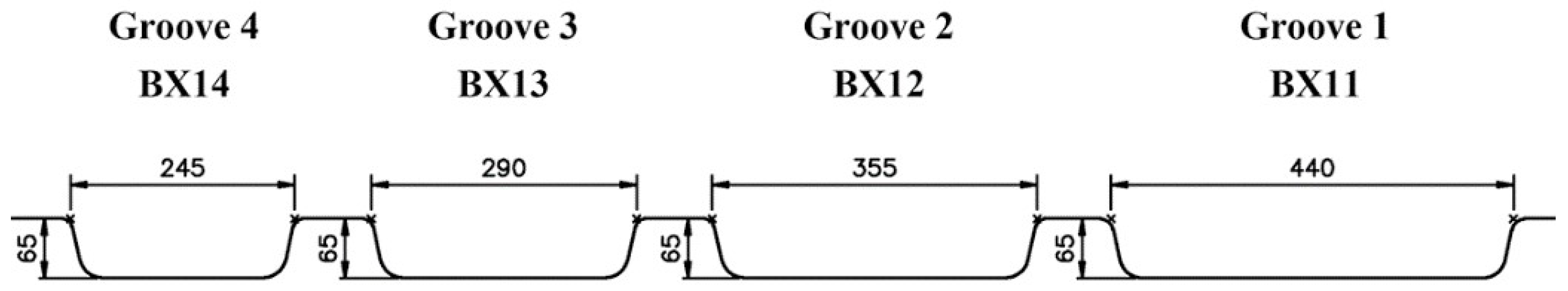
2.1. 3D FE Model of the Hot Rough Rolling Process for Round Bar

The hot rough rolling process of the GCr15 bar was modeled based on the production-line arrangement. The initial cast blooms with 505 mm × 385 mm × 5800 mm were heated to 1150 °C in a furnace. After descaling, the blooms were rolled to intermediate billets with a cross-section of 200 mm × 200 mm by several passes using a high-power rough rolling machine. Then the billets were cooled to 940 °C and rolled to final a Φ150 mm round bar by 10 continuous passes of finishing rolling, followed by air cooling to room temperature. Two rough rolling schedules were designed, as shown in Table 1. The rough rolling reduction was assigned to 13 passes in case no.1 based on the traditional rolling pass design, which is already utilized in industry. The same rough rolling reduction was assigned to 11 passes in case no.2 in order to increase the rolling efficiency and the reductions in each pass. Box groove shapes, as shown in Figure 1, were used in the rough rolling process as indicated by BX. The symbol T in the groove shape means a transverse reduction by turning over the bloom.
The commercial software MSC. Marc (2017, MSC Software corporation, Irvine, CA, USA) was used to establish the FE model. Figure 2 schematically shows the establishing process. Concerning the symmetry of hot bar rolling, one-quarter of the bloom and ½ the roller of each pass were modeled. The length of the bloom was set as 1000 mm to obtain a steady-state field of plastic deformation, while the inter pass time was calculated from real dimensions. The roller was assumed to be a rigid body with prescribed rotating velocity. The material parameters of GCr15 bearing steel, including heat capacity, Yong’s modulus, flow stress, etc. were applied to the bloom as an elastoplastic deformable-body. The heat transfer between the bloom and the environment in the forms of convection and radiation was considered. A contact heat transfer parameter of 9.5 kW/m2 °C was used to define the heat transfer between the roller and bloom during rolling. The factor of heat generation by plastic deformation work was set up as 0.9 in the FE model [24,25]. Two movable pushers were added near the ends of the bloom to control the reverse movement of the bloom. The groove change and gap set were realized by the speed assignment through the subroutine. Since the initial dimension of the bloom is relatively large and the heat dissipation in the descaling process is limited, the initial temperatures of the blooms are estimated to be homogenously distributed at a temperature of 1150 °C. Fierce heat dissipation in the descaling process was simulated. Because as many as 13 passes need to be modeled, the elements will be distorted and cannot achieve convergence results. So, the whole rough rolling process was divided into two FE models, i.e., the first 6 passes were enclosed in one model, and the later passes were in another model. The state variables, including temperature, grain size, etc., were transmitted from the first FE model to the second model by an in-house developed subroutine.

2.2. Austenite Grain Size Prediction during Hot Deformation

During the hot deformation of GCr15 bearing steel, the austenite grain size undergoes extensive evolution in the forms of DRX, SRX, MDRX, and GG. The fields of temperature, strain, strain rate, etc., of the hot bar rolling can be calculated by the FE model. It is recommended that the variation in austenite grain closely relates to these field variables. Therefore, the constitutive models of DRX, SRX, MDRX, and GG for GCr15 steel in previous literature were programed and coupled with the developed FE model [13,23]. The subprogram reads the temperature data, deformation strain, strain rate, etc., from the FE model and predicts the austenite grain evolution based on the constitutive models. Then the predicted austenite grain size and flow stress will be sent to the FE model to update the deformation resistance in the following step. The detailed procedures can be referred to in our previous papers [26,27].

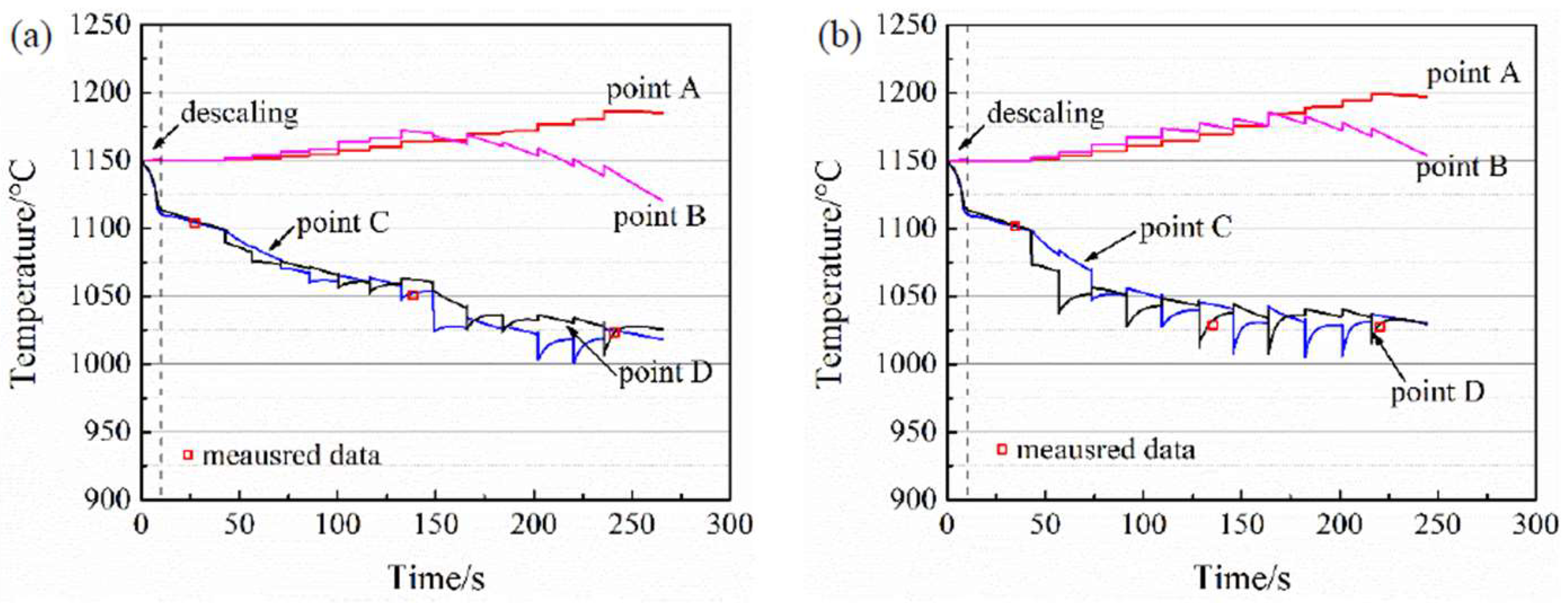
2.3. Experiment Verification

The rolling experiments were performed on an industry line in Henan Jiyuan Iron and Steel Group Co., Ltd., Henan, China. Two blooms were heated, descaled, and rough rolled under the rolling schedules listed in Table 1, followed by the same finishing rolling pass design. The temperatures at specified positions were measured to verify the simulation results. Since the intermediate rods have a dimension of over 200 mm × 200 mm, it is hard to cut the rod by the online cutting machine and cool to room temperature in a short period. Moreover, the method of using an oxyacetylene flame cutting will destroy the internal microstructure. Therefore, no specimens were sampled from the intermediate rods. Samples were taken from different cross-section positions of the final bars. After mechanical polishing and etching in a 4% nitric alcohol solution, the microstructures were examined under an optical microscope (Zeiss Axio Scope A1, Carl Zeiss Microscopy GmbH, Jena, Germany).

3. Results and Discussion

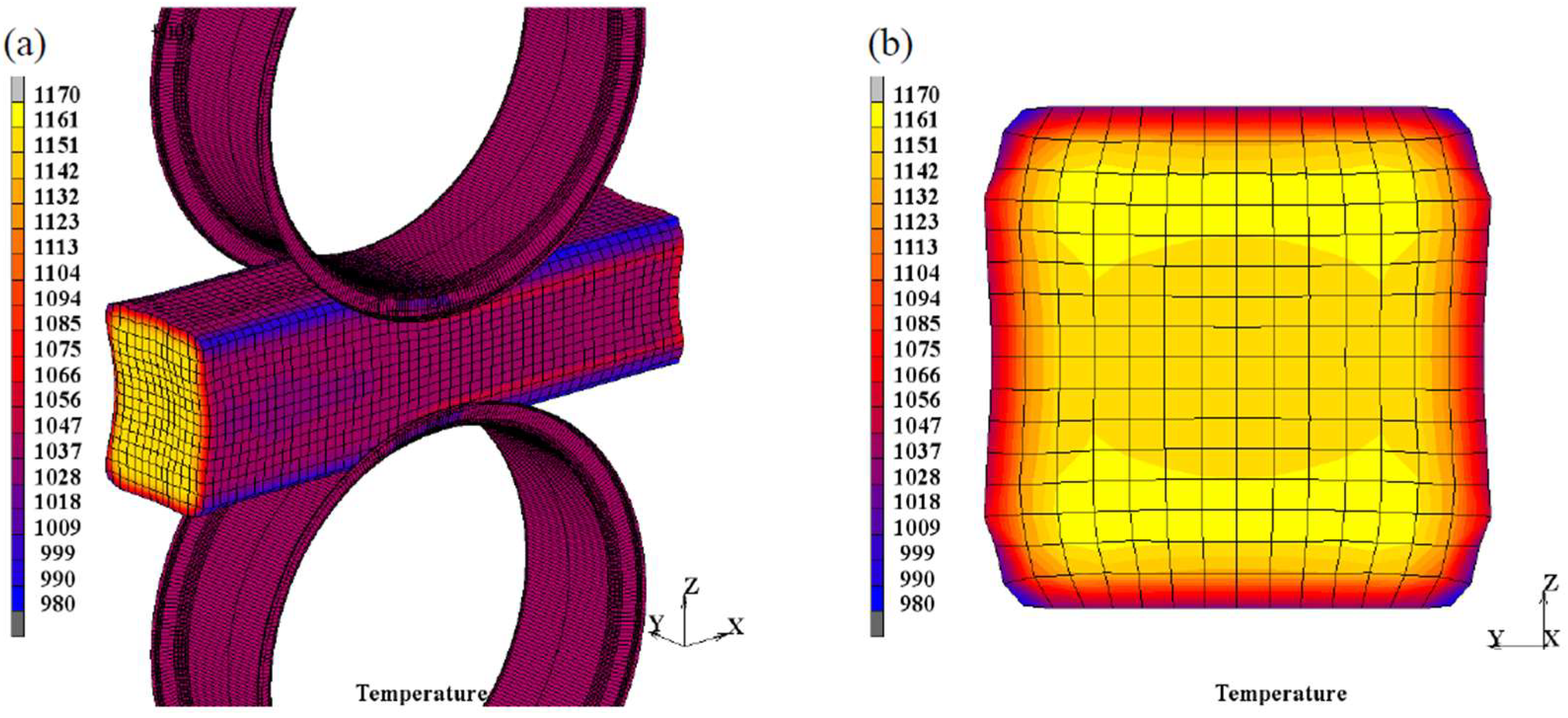
3.1. Temperature Profile Variations

Figure 3 shows a typical temperature distribution in the cross-section of the rod during rough rolling. After five passes of rough rolling in case no.1, the surface temperature was around 1070 °C, while the internal temperature was still around 1150 °C. Moreover, the temperature at half of the radius from the center, indicated as B in Figure 2, had the highest temperature of about 1160 °C. The heat dissipation of the bloom is mainly in two forms, i.e., heat convection and radiation to the environment between passes and contact heat transfer between the hot bloom and cold rollers during rolling. This causes a decreasing temperature in the surface regions. In the simulation, part of the plastic deformation work is supposed to be transferred into heat. Meanwhile, because of the large bloom cross-section used in this work, the heat conduction from the center to the surface is relatively slow. Therefore, the temperature at the center regions had a higher value. Additionally, it should be mentioned that there exists a high-temperature gradient in the near-surface region, while the internal temperature gradient is smaller, as clearly shown in Figure 3. This means that the detected temperature values by non-contact instruments cannot be easily used to estimate the actual temperatures of the bloom with a large cross-section. The temperature distributions in other passes or in case no.2 show similar morphologies.
The temperature profiles vary throughout the rough rolling process due to the varying deformation and heat dissipation conditions. To characterize the temperature distribution during the rough rolling process, the temperature variations at specified positions A–D, as marked in Figure 2a, are tracked and plotted in Figure 4. The stepped temperature jumps in the curves indicate the rolling state. This is because the fierce heat transfer occurs between the bloom and rollers during rolling, causing the obvious temperature drop at the surface. Meanwhile, the temperatures of the inner part seemed to increase along with the rough rolling process. This suggests that the heat generated by plastic deformation is higher than the heat dissipation in these regions during rough rolling. The temperatures measured online are also plotted in Figure 4. It can be seen that the simulation results agree well with the detected data, confirming the reliability of the simulation.
The bloom was heated to 1150 °C and taken out of the furnace. In the descaling process, the surface oxidation layer was destroyed and cleared by high-pressure water. A considerable amount of heat is also removed by the water, resulting in a temperature drop of about 100 °C at the surface. The internal part almost maintains the initial temperature of 1150 °C in the descaling process and subsequent holding period. This implies that the heat conduction from the center to the surface is slow for the bloom with a large cross-section. The surface temperature generally decreases along with the rough rolling process. Due to the turning over of the bloom in some passes, the temperatures at surface points C and D decrease in turn, in which the temperature at the contacting arc decreases more than in the other regions. In contrast, the temperatures at the center (point A) increase slowly along with the rough rolling process. The temperature at point B shows a complex morphology in which the temperature values increase first and then decrease in later passes. As illustrated above, the temperature increase in the center means that the heat generated by deformation is higher than the heat lost by conduction. It is interesting to find that in the first several passes, the temperature at point B is higher than that of central point A and then decreases in the later passes. This implies that in the first passes, the deformation strain is higher at point B than that at the center. In the later passes, the heat loss caused by conduction becomes dominant and results in a temperature decrease.
The surface temperatures at the surfaces are much lower than those in the internal part. However, the temperature cloud map in Figure 3b already shows that a sharp temperature gradient only exists in the near-surface region, while a relatively smaller temperature gradient exists in the internal part. Thus, the blooms are almost deformed at high temperatures during the rough rolling process. By comparison, the heavy reduction in case no.2 causes a smaller temperature increase in the internal regions than that in the case of no.1. The internal part of the bloom mainly deformed at the temperatures of 1125 °C~1175 °C in case no.1, while at the temperature of 1155 °C~1200 °C in case no.2.

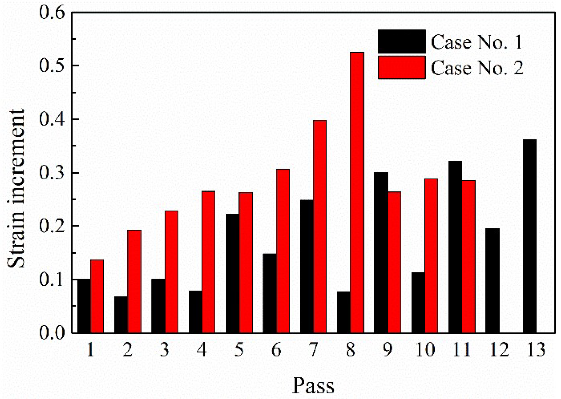
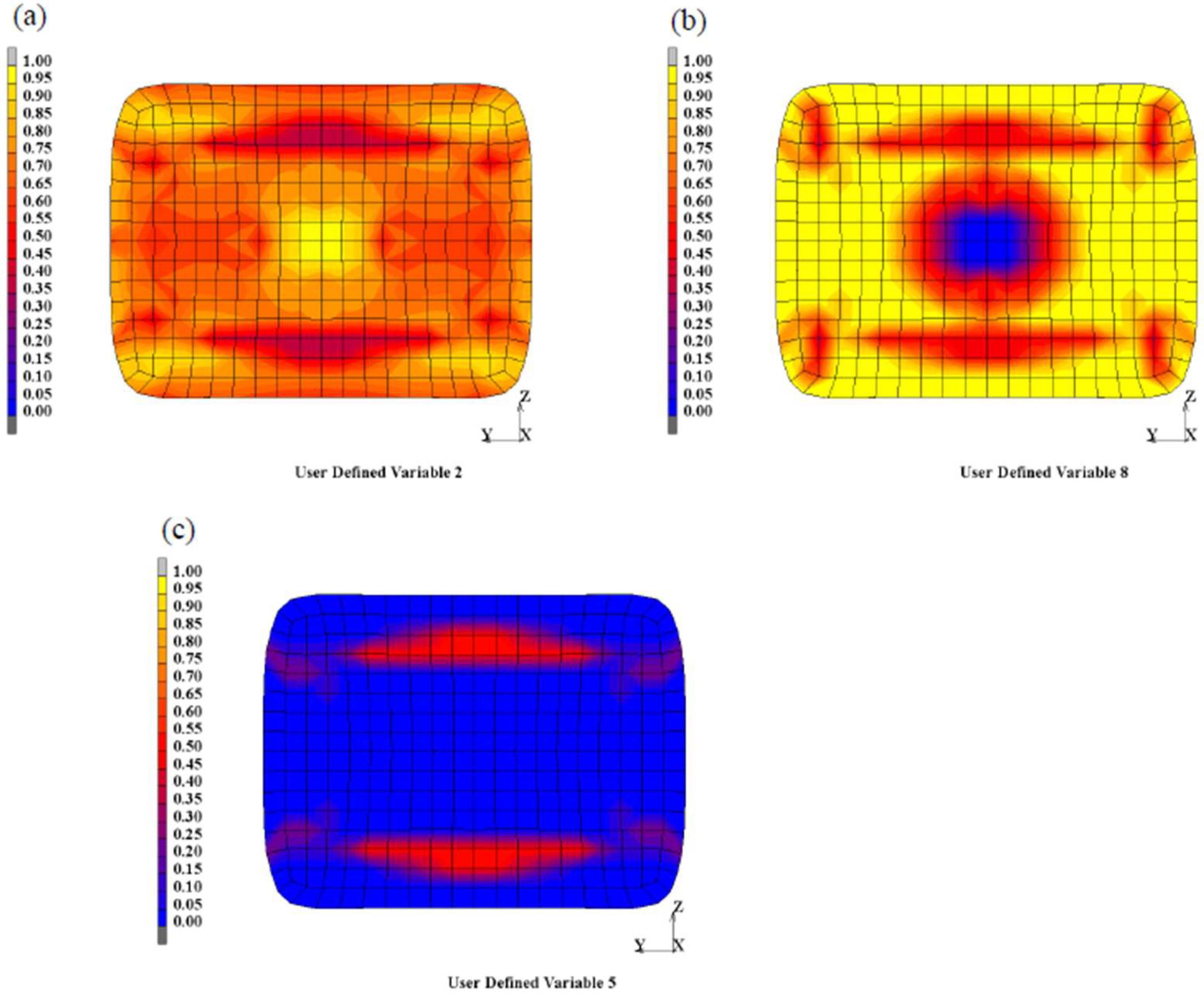
3.2. Distributions of Plastic Strain

Figure 5 shows the cross-section shape and strain distributions after specified passes with similar cross-section areas in cases no.1 and no.2 during rough rolling. It can be seen that the strain distributes inhomogeneously in cross-section. After the first passes, the maximum plastic strain is located at the top and bottom areas of the cross-section, and the minimum plastic strain is located at the center and sides. This clearly indicates that the deformation does not penetrate into the center region because of the large cross-section of the initial bloom. With the increasing passes, the deformation strains gradually increase. The strain values at the central regions are still lower than those at the surface regions. Due to the turning over of bloom during rolling, the top and bottom surface regions have similar strain values as the sides. Because higher reductions are applied, the strain values in the cross-section of case no.2 are higher than those in case no.1.
The strain increment at each pass can be obtained by tracking the equivalent strains before and after the passes. In order to analyze the effect of heavy rolling reduction on the deformation, the strain increment at center point A for each pass was calculated, as shown in Figure 6. Generally, the strain increment at each pass is positively related to the reduction design. Additionally, the strain increment in case no.1 is less than those in case no.2. This is because a heavy reduction with 11 passes in all is applied in case no.2, while the same total reduction is divided into 13 passes in case no.1. This demonstrates that the heavy reduction design in rough rolling can introduce higher strains at the center region for a bloom with a large cross-section.
Moreover, when analyzing in detail by comparing Figure 6 and Table 1, it can be inferred that the degrees of stain increment by the same reduction are different for passes. For example, reductions of around 22% are applied to the sixth, seventh, and eighth passes in case no.2, while the plastic strain increments at the center are 0.3, 0.4, and 0.53, respectively. The same tendency can be found in the 9th and 11th passes in case no.1. The imposed strain at the center region is supposed to be caused by two factors, namely the applied reduction and the temperature distribution. The temperature in the central regions increases along with the rough rolling process, as illustrated in the above section. The deformation resistance of GCr15 steel decreases with the increasing temperature. Therefore, the increasing temperature in the center regions during rough rolling causes higher plastic deformation at later passes than in previous passes even though the same reduction design is applied. The coupling effects of temperature and deformation are complex. The temperature increment results from the deformation, and it enhances the deformation further. Using the developed FE model, this coupling effect of temperature and strain can be captured.

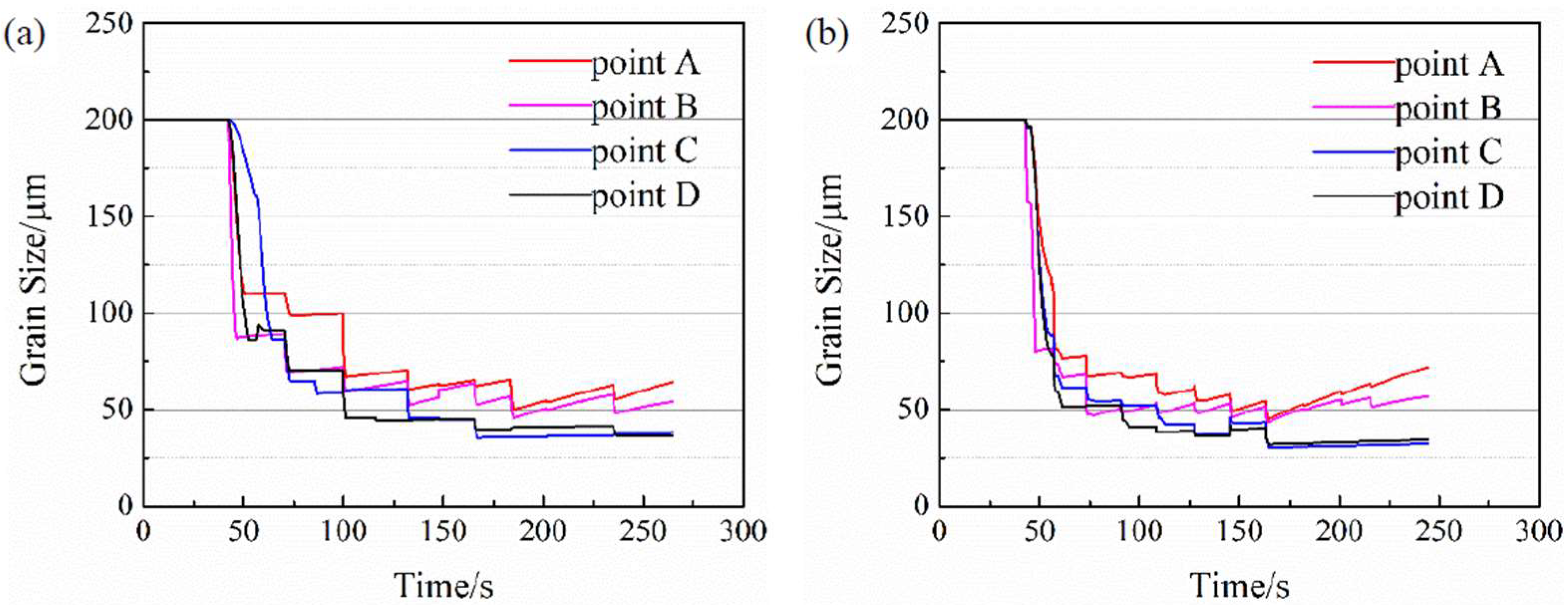
3.3. Austenite Grain Size Evolution

The austenite grain size distributions were calculated by using the developed grain-size prediction subroutine. Figure 7 shows the austenite grain size distribution in the cross-section at specified passes with similar dimensions for case no.1 and case no.2. The predicted austenite grain size at the surface region is smaller, and the interior grains are a little bigger. It can be found that the austenite grain size distribution is more homogeneous in case no.2 than that of case no.1 when the billets have similar cross-section areas. This is supposed to be related to the large strain induced by the heavy reduction. The evolution of the austenite grain size during the whole rough rolling process was plotted along with the time, as shown in Figure 8. It can be seen that the austenite grains are greatly refined in the first two or three passes. Then the grain size reduces gradually along with the passes. During the holding period, the grain size increases a little in the form of GG. Especially for the center regions at later passes, the GG effect is obvious because of the high temperature of this region. By comparing the grain size evolution in cases no.1 and no.2, the grain size is refined much more intensively in the first passes in the heavy reduction design. This phenomenon is supposed to be significant for the bar rolling with a large cross-section, which is beneficial for alleviating the solidification defects and improving the microstructure homogeneity.
The refinement of the austenite grain size in rough rolling is caused by the occurrence of recrystallization, including DRX, MDRX, and SRX. The degree of recrystallization in the eight pass of case no.2 is shown in Figure 9 as a representative example. The strain increment at the center region is up to over 0.5, initiating the DRX during rolling (Figure 9a). However, the deformation period is short, in which completed DRX is not obtained. Thus the recrystallized grains will continue to grow in the subsequent period after rolling, i.e., the occurrence of MDRX. Meanwhile, the degree of SRX in this period is very limited due to the occurrence of DRX and MDRX. The grain size evolution in this pass is shown in Figure 10. It can be found that the occurrence of DRX and MDRX refined the austenite grain size, while during the holding period after rolling, the occurrence of GG increased the grain size.

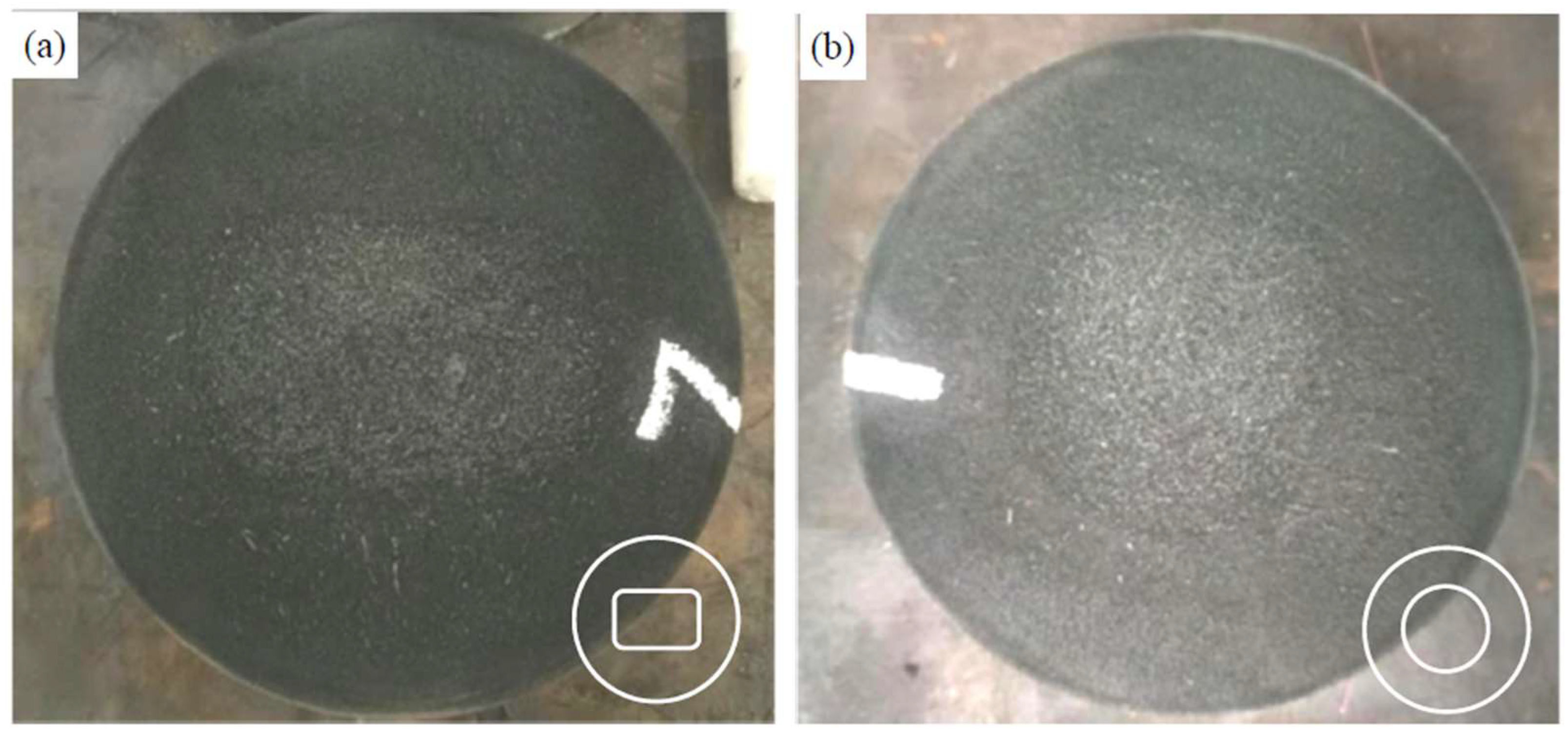
3.4. Microstructure Verification after Hot Bar Rolling

The microstructures of the bars after hot rolling were examined. The microstructures at the central regions of the two cases are shown in Figure 11. The microstructures consisted of perlite and proeutectoid carbide after the hot bar rolling. Additionally, the proeutectoid carbide mainly formed prior to the austenite grain boundaries, indicating that the prior austenite grain morphology was formed before phase transformation. The grain size number (G) in the cross-section was determined according to the GB/T 6394-2017 and listed in Table 2. It implies that the fraction of coarse grains in case no.2 is much lower than those in case no.1. It also can be seen in Figure 11 that the grain size is a little smaller in case no.2 than that in case no.1. The difference between the two cases was the rough rolling pass design. Simulation results indicate that the heavy reduction design is efficient for the introduction of high strain at the center region and improved the austenite grain size homogeneity in rough rolling. The refinement effects of austenite grains evolved into the final microstructure. Therefore, the grain size and microstructure homogeneity are improved by the heavy reduction design during rough rolling.
The macro-photographs of the etched cross-section of the hot-rolled bars were also examined, as shown in Figure 12. Since the bloom with a large cross-section was used in the work, severe macrosegregation was formed in the cast bloom caused by the relative movement of solid-liquid flow during solidification [28]. Moreover, this macrosegregation defect is difficult to be eliminated by rolling. Figure 12 shows that the rough rolling design affects the morphology of macrosegregation. The profile of macrosegregation in case no.1 seems to retain the rectangle shape while it became round and a little smaller in case no.2. The sustained rectangle shape of macrosegregation is supposed to cause anisotropy in the cross-section, which will greatly influence the performance stability of the machined components. More strains are introduced to the bloom in case no.2 by the heavy reduction design, which is thought to improve the macrosegregation of the bars. Moreover, hydrostatic pressure is a key factor for improving the shrinkage during deformation [29,30]. Therefore, the high plastic strain and stress in the inter regions by heavy reduction design will definitely improve the inter quality of the bars. This improvement of macrosegregation by heavy rough rolling reduction design is beneficial for the subsequent heat treatment of the hot rolling bars. It should be pointed out that the heavy reduction design in case no.2 increased the rolling force, which is near the motor power limit of the industrial rolling mill. Therefore, the equipment capability should also be considered in the rolling pass design.

4. Conclusions

  • A thermal-mechanical coupled FE model for a rough rolling process for a GCr15 bar was developed. Using the data transmitting method, as many as 13 passes of rolling can be modeled. The austenite grain size evolution during hot deformation, including DRX, MDRX, SRX, and GG, was programmed in the subroutine and coupled with the FE model.
  • The temperature and strain distributions of the bloom with a large cross-section during rough rolling were inhomogeneous in the cross-section. The inner part was deformed at high temperatures due to the heat generation by deformation, while the surface temperature decreased along with the rolling process. The heavy reduction design in case no.2 introduced more strains at the center region.
  • The austenite grain size evolution was captured by the FE model. In the first two or three passes, the austenite grains were refined significantly because of the occurrence of DRX and MDRX, while the refinement effects were lessened in the later passes. The heavy reduction design possesses an adequate refinement effect and achieves a more homogeneous austenite grain size distribution in cross-section as compared to the small reduction schedule.
  • The microstructures of the bar with different rough rolling schedules were examined. The grain size was refined, and the microstructure homogeneity and macrosegregation were improved by applying the heavy reduction design in rough rolling. This is supposed to be related to the increasing strain and promoted recrystallization by the heavy reduction in rough rolling.

Author Contributions

H.H., X.Z. and C.Z.; methodology and experiments, H.H., H.D., X.Y. and W.W.; writing—original draft preparation, H.H., H.D. and X.Y.; writing—review and editing, X.Z., C.Z. and W.W. All authors have read and agreed to the published version of the manuscript.

Funding

This research was funded by the Joint Research Fund of Natural Science Foundation of Liaoning-the State Key Laboratory of Rolling and Automation, Northeastern University (2019KF0506).

Institutional Review Board Statement

Not applicable.

Informed Consent Statement

Not applicable.

Data Availability Statement

Data are contained within the article.

Conflicts of Interest

The authors declare no conflict of interest.

References

  1. Bhadeshia, H.K.D.H. Steels for bearings. Prog. Mater. Sci. 2012, 57, 268–435. [Google Scholar] [CrossRef]
  2. Li, S.; Xiao, M.; Ye, G.; Zhao, K.; Yang, M. Effects of deep cryogenic treatment on microstructural evolution and alloy phases precipitation of a new low carbon martensitic stainless bearing steel during aging. Mater. Sci. Eng. A 2018, 732, 167–177. [Google Scholar] [CrossRef]
  3. Liu, Y.-J.; Xu, G.-D.; Wang, Y.-C.; Zhong, H.-G.; Li, L.-J.; Wang, B.; Zhai, Q.-J. Effects of pulse magneto-oscillation on GCr15 bearing steel continuous casting billet. J. Iron Steel Res. Int. 2022, 29, 144–150. [Google Scholar] [CrossRef]
  4. Ji, F.; Li, C.; Tang, S.; Liu, Z.; Wang, G. Effects of carbon and niobium on microstructure and properties for Ti bearing steels. Mater. Sci. Technol. 2015, 31, 695–702. [Google Scholar] [CrossRef]
  5. Han, H.; Zhao, X.; Zhao, X.; Wan, C.; Wang, W. Effect of proeutectoid carbide on heredity in microstructure-mechanical properties and fatigue life of GCr15 bearing steel. Metall. Res. Technol. 2017, 114, 208. [Google Scholar] [CrossRef]
  6. Nishioka, K.; Ichikawa, K. Progress in thermomechanical control of steel plates and their commercialization. Sci. Technol. Adv. Mater. 2012, 13, 023001. [Google Scholar] [CrossRef]
  7. Liang, J.-X.; Wang, Y.-C.; Cheng, X.-W.; Li, Z.; Du, J.-K.; Li, S.-K. Microstructure and mechanical properties of a Cr-Ni-W-Mo steel processed by thermo-mechanical controlled processing. J. Iron Steel Res. Int. 2021, 28, 713–721. [Google Scholar] [CrossRef]
  8. Liu, Z.G.; Gao, X.H.; Xiong, M.; Li, P.; Misra, R.D.K.; Rao, D.Y.; Wang, Y.C. Role of hot rolling procedure and solution treatment process on microstructure, strength and cryogenic toughness of high manganese austenitic steel. Mater. Sci. Eng. A 2021, 807, 140881. [Google Scholar] [CrossRef]
  9. Yao, S.J.; Du, L.X.; Wang, G.D. Microstructure of Nb-Bearing Pipeline Steel with Improved Property Applying Ultrafast Cooling Process. Steel Res. Int. 2014, 85, 60–66. [Google Scholar] [CrossRef]
  10. Yang, Q.-M.; Lin, Y.-C.; Guo, J.-Z.; Wang, C.; Chen, Z.-J.; Chen, K.-G.; Zhu, J.-C. Spheroidization and dynamic recrystallization mechanisms of a novel HIPed P/M superalloy during hot deformation. J. Alloys Compd. 2022, 910, 164909. [Google Scholar] [CrossRef]
  11. Sakai, T.; Belyakov, A.; Kaibyshev, R.; Miura, H.; Jonas, J.J. Dynamic and post-dynamic recrystallization under hot, cold and severe plastic deformation conditions. Prog. Mater. Sci. 2014, 60, 130–207. [Google Scholar] [CrossRef] [Green Version]
  12. Qiao, S.-B.; Liu, Z.-D.; He, X.-K.; Xie, C.-S. Metadynamic recrystallization behaviors of SA508Gr.4N reactor pressure vessel steel during hot compressive deformation. J. Iron Steel Res. Int. 2021, 28, 46–57. [Google Scholar] [CrossRef]
  13. Yue, C.-X.; Zhang, L.-W.; Liao, S.-L.; Pei, J.-B.; Gao, H.-J.; Jia, Y.-W.; Lian, X.-J. Research on the dynamic recrystallization behavior of GCr15 steel. Mater. Sci. Eng. A 2009, 499, 177–181. [Google Scholar] [CrossRef]
  14. Yin, F.; Hua, L.; Mao, H.; Han, X.; Qian, D.; Zhang, R. Microstructural modeling and simulation for GCr15 steel during elevated temperature deformation. Mater. Des. 2014, 55, 560–573. [Google Scholar] [CrossRef]
  15. Yang, H.; Yao, P.; Liu, H. Study on austenite recrystallization softening behavior of GCr15 steel. IOP Conf. Ser. Mater. Sci. Eng. 2019, 493, 012034. [Google Scholar] [CrossRef]
  16. Zhang, C.; Zhang, L.; Xu, Q.; Xia, Y.; Shen, W. The kinetics and cellular automaton modeling of dynamic recrystallization behavior of a medium carbon Cr-Ni-Mo alloyed steel in hot working process. Mater. Sci. Eng. A 2016, 678, 33–43. [Google Scholar] [CrossRef]
  17. Zhang, C.; Zhang, L.; Shen, W.; Liu, C.; Xia, Y.; Li, R. Study on constitutive modeling and processing maps for hot deformation of medium carbon Cr-Ni-Mo alloyed steel. Mater. Des. 2016, 90, 804–814. [Google Scholar] [CrossRef]
  18. Liu, D.; Ding, H.; Hu, X.; Han, D.; Cai, M. Dynamic recrystallization and precipitation behaviors during hot deformation of a κ-carbide-bearing multiphase Fe–11Mn–10Al–0.9C lightweight steel. Mater. Sci. Eng. A 2020, 772, 138682. [Google Scholar] [CrossRef]
  19. Li, C.S.; Liu, X.H.; Wang, G.D. Simulation on temperature field of 50CrV4 automobile gear bar steel in continuous rolling by FEM. J. Mater. Process. Technol. 2002, 120, 26–29. [Google Scholar] [CrossRef]
  20. Perez-Alvarado, A.; Arreola-Villa, S.A.; Calderon-Ramos, I.; Servin Castaneda, R.; Mendoza de la Rosa, L.A.; Chattopadhyay, K.; Morales, R. Numerical Simulation of the Hot Rolling Process of Steel Beams. Materials 2021, 14, 7038. [Google Scholar] [CrossRef]
  21. Hong, H. Roll Pass Design and Simulation on Continuous Rolling of Alloy Steel Round Bar. Procedia Manuf. 2019, 37, 127–131. [Google Scholar] [CrossRef]
  22. Wang, X.; Chandrashekhara, K.; Lekakh, S.N.; Van Aken, D.C.; O’Malley, R.J. Modeling and Simulation of Dynamic Recrystallization Behavior in Alloyed Steel 15V38 during Hot Rolling. Steel Res. Int. 2018, 90, 1700565. [Google Scholar] [CrossRef]
  23. Yue, C.; Zhang, L.; Liao, S.; Gao, H. Mathematical models for predicting the austenite grain size in hot working of GCr15 steel. Comput. Mater. Sci. 2009, 45, 462–466. [Google Scholar] [CrossRef]
  24. Pietrzyk, M. Finite-element simulation of large plastic deformation. J. Mater. Process. Technol. 2000, 106, 223–229. [Google Scholar] [CrossRef]
  25. Kim, S.H.; Yeon, S.-M.; Lee, J.H.; Kim, Y.W.; Lee, H.; Park, J.; Lee, N.-K.; Choi, J.P.; Aranas, C.; Lee, Y.J.; et al. Additive manufacturing of a shift block via laser powder bed fusion: The simultaneous utilisation of optimised topology and a lattice structure. Virtual Phys. Prototyp. 2020, 15, 460–480. [Google Scholar] [CrossRef]
  26. Sendong, G.; Liwen, Z.; Chi, Z.; Jinhua, R.; Yu, Z. Modeling the Effects of Processing Parameters on Dynamic Recrystallization Behavior of Deformed 38MnVS6 Steel. J. Mater. Eng. Perform. 2015, 24, 1790–1798. [Google Scholar] [CrossRef]
  27. Shen, W.; Zhang, C.; Zhang, L.; Xu, Q.; Xu, Y.; Bie, L. Investigation of recrystallization behavior of large sized Nb-V microalloyed steel rod during thermomechanical controlled processing. J. Mater. Res. 2017, 32, 2389–2396. [Google Scholar] [CrossRef]
  28. Ge, H.; Ren, F.; Li, J.; Hu, Q.; Xia, M.; Li, J. Modelling of ingot size effects on macrosegregation in steel castings. J. Mater. Process. Technol. 2018, 252, 362–369. [Google Scholar] [CrossRef]
  29. Feng, C.; Cui, Z.; Shang, X.; Liu, M. An evolution model for elliptic-cylindrical void in viscous materials considering the evolvements of void shape and orientation. Mech. Mater. 2017, 112, 101–113. [Google Scholar] [CrossRef]
  30. Nakasaki, M.; Takasu, I.; Utsunomiya, H. Application of hydrostatic integration parameter for free-forging and rolling. J. Mater. Process. Technol. 2006, 177, 521–524. [Google Scholar] [CrossRef]
Figure 1. Groove profiles used in the rough rolling process.
Metals 12 00812 g001
Figure 2. FE model of the hot rough rolling process. (a) symmetry of rod rolling and representative positons of A, B, C and D (b) geometry model with multi-grooves.
Metals 12 00812 g002
Figure 3. The temperature distribution in fifth pass of rough rolling in case no.1. (a) 3D morphology; (b) temperature profile in cross-section.
Metals 12 00812 g003
Figure 4. The temperature variations along the rough rolling process. (a) case no.1; (b) case no.2. Point A–D can be referred to Figure 2a.
Metals 12 00812 g004
Figure 5. The strain distributions in cross-section along the rough rolling process. (a) 1st pass in case no.1; (b) 5th pass in case no.1; (c) 7th pass in case no.1; (d) 1st pass in case no.2; (e) 3rd pass in case no.2; (f) 5th pass in case no.1.
Metals 12 00812 g005aMetals 12 00812 g005b
Figure 6. Comparison of the plastic strain increment at center in each pass for case no.1 and no.2.
Metals 12 00812 g006
Figure 7. The austenite grain size distributions in cross-section. (a) 12th pass of case no.1; (b) 8th pass of case no.2; (c) 13th pass of case no.1; (d) 11th pass of case no.2.
Metals 12 00812 g007
Figure 8. The austenite grain size evolution in cross-section along the rough rolling process. (a) case no.1; (b) case no.2. Point A-D can be referred to Figure 2a.
Metals 12 00812 g008
Figure 9. The degree of recrystallization occurrence in the 8th pass of case no.2. (a) DRX; (b) MDRX; (c) SRX.
Metals 12 00812 g009
Figure 10. The grain size evolution at center in the 8th pass of case no.2.
Metals 12 00812 g010
Figure 11. The center microstructure of the bars after hot bar rolling. (a,b) case no.1; (c,d) case no.2.
Metals 12 00812 g011
Figure 12. The photos of macrosegregation and shrinkage in cross-section after hot bar rolling. (a) case no.1; (b) case no.2.
Metals 12 00812 g012
Table 1. Main parameters of the rolling schedules.
Pass NumberNo.1No.2
Groove ShapeHeight
(mm)
Width
(mm)
Reduction
(%)
Groove ShapeHeight
(mm)
Width
(mm)
Reduction
(%)
1BX114554158.9BX1144040211.9
2BX114254156.6BX1137042015.9
3TBX1136543512.1TBX1133539820.2
4TBX113404355.5BX1131035522.1
5BX1136035017.2TBX1128532819.7
6BX1231635012.2BX1225530522.3
7TBX1229533515.7TBX1224027421.3
8TBX132703458.5BX1321026023.4
9BX1326027024.6TBX1323022011.5
10BX132352859.6TBX1318523519.6
11TBX1323024519.3BX1320020014.9
12TBX1319525515.2 //
13BX1420020021.6 //
Table 2. Determination of the grain size number (G) in cross-section after hot bar rolling.
RegionsCenter1/2 Radius from CenterSurface
Case no.1G6.0 (10%), G4.5 (80%), G3.0 (10%)G5.0 (60%), G3.0 (30%),G5.0
Case no.2G6.0 (60%), G5.0 (30%), G3.5 (10%)G6.0 (20%), G5.0 (70%), G3.5 (10%)G6.0
Publisher’s Note: MDPI stays neutral with regard to jurisdictional claims in published maps and institutional affiliations.

