Article

Correlation between Microstructure and Mechanical Properties of Welded Joint of X70 Submarine Pipeline Steel with Heavy Wall Thickness

1
Key Laboratory of Material Physics, Ministry of Education, School of Physics and Microelectronics, Zhengzhou University, Zhengzhou 450052, China
2
School of Electrical Engineering, Zhengzhou University, Zhengzhou 450001, China
*
Author to whom correspondence should be addressed.
Metals 2022, 12(5), 716; https://doi.org/10.3390/met12050716
Submission received: 20 March 2022 / Revised: 14 April 2022 / Accepted: 19 April 2022 / Published: 22 April 2022
(This article belongs to the Special Issue Advanced Technology in Microalloyed Steels)

Abstract

:
This paper aims to study the relationship between the microstructure and the mechanical properties of X70 submarine pipeline steel with 40.5 mm thickness. The microstructure was examined by using optical microscopy, scanning electron microscopy and an electron backscattered diffractometer, while the mechanical properties were examined by using a hardness test, a tensile test, a Charpy impact test and a drop weight tear test (DWTT), respectively. The results show that the base metal (BM) of the pipe has a low yield ratio of 0.83 and an excellent elongation of more than 45%. The DWTT shear area of the steel plate reaches 87%, showing excellent low-temperature toughness. The Charpy impact energy increases when the distance from the fusion line increases, and it reaches a maximum at the BM near the heat-affected zone (HAZ) due to the small martensite-austenite (MA) constituents and fine grains. The concentrated distribution of blocky/slender MA constituents along the prior austenite grain boundaries of the intercritically reheated coarse-grained HAZ and the large MA constituents are the main reasons for the deteriorating impact toughness. Delamination cracks in the DWTT fracture surface only occurred in the midthickness of a sample with a small opening width that spread about 2.1 mm perpendicular to the DWTT fracture surface and were finally arrested at the acicular ferrite clusters containing a high density of high-angle boundaries.

1. Introduction

In recent decades, pipeline transportation has been widely considered the most efficient and economical transportation method for crude oil and natural gas. However, the environment of the deep sea is changeable and complex, not only with respect to the sea water temperature at the bottom but also to sundry geological hazards, such as underwater landslides and earthquakes, that can easily cause pipes to break and fracture. Therefore, high-strength and toughness and highly weldable pipeline steel with a high gauge is required to ensure transportation efficiency and safety [1,2,3,4]. However, the properties of high strength and excellent toughness in pipeline steel can be deteriorated by local brittle zones that form during welding thermal cycles [3,5], especially in thick submarine pipelines with high heat input.
The coarse grain heat-affected zone (CGHAZ) adjacent to the fusion line (FL) always has the lowest fracture toughness due to the formation of unfavorable microstructures such as large prior austenite grains, coarse bainite microstructures and martensite-austenite (MA) constituents and precipitates [5,6,7].
It is well established that the presence of large and high-volume fraction MA constituents in the heat-affected zone (HAZ) causes decreased toughness [6]. In addition, the lack of space between blocky MA constituents exhibits a deleterious influence on fracture toughness because the stress concentration will be enlarged due to the transformation-induced, overlapping stress fields [8]. Di and Cai et al. [9] also suggested that this toughness shows a considerable decrease when MA constituents are distributed at the grain boundaries and connected into chains.
The microstructure of a welded joint is dependent on the chemical composition and welding conditions of the pipe, including the welding heat input and pipe thickness, which define the cooling rates [10]. Although there have been many studies on the properties of the welded joint of pipeline steel [4,11], further research on submarine pipeline steel with thicknesses greater than 40 mm is needed due to the rigorous requirements regarding low-temperature toughness and strength.
In the present study, X70 submarine pipeline steel with a thickness of over 40 mm has excellent tensile properties and drop weight tear test (DWTT) fracture features. When a large heat input was applied during the welding process, variations in the microstructure and mechanical properties of different regions of the welded joint occurred. To describe the detailed mechanism of microstructural evolution and mechanical property variation after welding, hardness testing, tensile testing, low-temperature Charpy V notched impact testing and DWTT were carried out.

2. Materials and Methods

The material used in this study was X70 submarine pipeline steel plate with a 40.5 mm thickness, which was obtained after thermo-mechanical control processing, followed by generating a pipe with outer diameter of 691 mm. The chemical composition was mainly composed of C 0.044, Mn 1.56, P 0.009, S 0.009, Si 0.25, Ni + Cr + Cu + Mo 0.475, Nb 0.049 and Ti 0.020, wt.%.
Due to the thickness of the pipeline steel, a heat input of 96 kJ/cm was used to ensure the welding process occurred consistently and as expected. As shown in Figure 1, the welded joint includes the weld metal zone (WM), the HAZ and the base metal zone (BM). Under the effects of double-pass longitudinal submerged arc welding, the HAZ can be separated into CGHAZ, the fine grain HAZ (FGHAZ), the intercritical HAZ (ICHAZ) and the subcritical HAZ (SCHAZ) [3]. Moreover, deep weld deposition was formed as a result of the large heat input. Reheated CGHAZ, which consists of unaltered CGHAZ (UA CGHAZ), supercritically reheated CGHAZ (SC CGHAZ), intercritically reheated CGHAZ (IC CGHAZ) and subcritically reheated CGHAZ (S CGHAZ), could have been very different from the CGHAZ due to the different second peak temperatures.
The tensile specimens were cut from the BM along the transverse and longitudinal directions, far from the HAZ. The tensile test on the BM was carried out using a tensile testing machine (ZWICK 1600; ZwickRoell, Ulm, Germany), and the gauge size of plate tensile specimens was 38.1 mm wide by 50 mm long by full material thickness. Round tensile specimens with a diameter of 12.7 mm were adopted on the WM in the midthickness. Three identical specimens were tested at each position during tensile test at room temperature.
Hardness test was performed on a digital hardness tester (XHD-2000TMSC; Vickers, Shanghai, China), with an indenting load of 9.8 N and loading time of 15 s. Measurements were made at four different positions of the welded joint, as shown by the solid red line in Figure 1. The positions of the hardness test were 2 mm away from the outside surface and midthickness, respectively. The distance between each neighboring indentation caused by the tester was 0.5 mm, in a direction from the FL to the BM near the HAZ.
V-notch Charpy impact test was conducted at −30 °C on a Charpy impact test machine (RKP 450; Derui, Guangdong, China) using specimens with dimensions of 10 mm × 10 mm × 50 mm. To indicate the change in toughness in the direction of thickness of the X70 steel welded joint, the specimens were sampled 2 mm away from the outside weld surface and weld root in the midthickness located in the outside weld, respectively, and two identical specimens were tested at each position. The sampling locations are shown in Figure 2a. Four notch zones were chosen for Charpy V-notch testing, including the WM centerline zone, FL zone, HAZ and BM zones. V-notch specimens at the FL zone were sampled at both 50% WM and 50% HAZ, whereas other specimens were notched at 2 mm away from the FL (FL + 2 mm), 5 mm away from the FL (FL + 5 mm) and in the BM zone near HAZ, in accordance with DNV-OS-F101 [12]. DWTT was performed on the steel plate with dimensions of 305 mm × 76.2 mm × 40.5 mm. The test was carried out at −20 °C on a drop weight tear testing machine (JL–100000; Shengwei, Shandong, China). The DWTT macroscopic fracture morphology is shown in Figure 2b and was cut along the red line on the specimen to observe delamination cracks. Microstructural analysis was conducted using a scanning electron microscope (SEM; JSM 6700F; Jeol, Tokyo, Japan) and optical microscope (OM; BX51M; OLYMPUS, Tokyo, Japan), and the specimens were mechanically polished and chemically etched for about 25 s using 4% Nital solution. To denote the presence of MA constituents, polished samples were etched using LePera’s reagent. The average size and volume fraction of the MA constituents in different regions of the HAZ were measured by using Image-Pro Plus software (IPP; Media Cybernetics, New York, UK).
Electron backscattered diffractometry (EBSD) analysis was used for the crystal analysis of the delamination cracks in a field emission scanning electron microscope (FESEM; ZEISS, Oberkochen, Germany). In this study, EBSD data were acquired at 20 kV with a 0.2 μm step size. The raw data were analyzed using HKL Channel 5 software (2007 version; Buehler, Oxford, UK) to acquire the crystallographic features.

3. Results

3.1. Mechanical Properties

The results of the tensile testing of the studied steel are shown in Table 1. According to the specification of DNV-OS-F101, all of the specimens tested in the present work satisfy the requirements of X70 submarine pipeline steel. For the BM, there is no significant difference in the tensile properties, whether in the longitudinal or transverse directions. The BM shows a low yield ratio of 0.83 and an excellent elongation of more than 45%. For WM, the yield strength and tensile strength are both higher than those of BM, which ensures that fractures will not occur in the WM (Table 1).
The DWTT is one of the most effective methods available to explore the fracture properties of steel. According to the API 5L SP3 standard of the American Petroleum Institute, the shear area of the plate’s fracture surface must attain more than 85%.
The DWTT fracture surface can be divided into four parts, as shown in Figure 2b: (1) the initial cleavage fracture surface near the pressed notch; (2) the ductile fracture; (3) the inverse cleavage fracture surface; (4) the hammer impact zone. The DWTT fracture surface was tortuous (Figure 2b), showing that the main crack propagation consumed a lot of energy [13,14]. However, when the main crack propagated to about half of the DWTT specimen width, its propagation direction was deflected by a large angle, and the ductile fracture mode was transformed into a brittle fracture mode in the inverse cleavage fracture.
In this study, the DWTT shear area of the steel plate was calculated according to the method in the literature [2], which reaches 87%, showing excellent low-temperature toughness. Delamination cracks exist in the midthickness of the plate of the DWTT fracture surface (Figure 2b). The propagation direction of the delamination cracks is perpendicular to the fracture surface and parallel to the rolling direction. The opening width of the delamination cracks in this study is small, so the delamination cracks are not included in the brittle fracture area, according to API RP 5L3.
Figure 3 shows the hardness values of the welded joint. The results indicate that the hardness of WM is relatively higher than that of the other regions. The hardness gradually decreases from the WM to the FGHAZ due to the welding softening that occurred during the thermal cycle of the welding process, which is where the quasi-polygonal ferrite (QPF) and fine polygonal ferrite (PF) occur and the second particles dissolve. It should be mentioned that the hardness of the samples that were 2 mm away from the outside weld surface is slightly higher than that of the midthickness region (see Figure 3a,b), which can be attributed to the differences in cooling rates during thermal welding cycles. Welding softening also occurs at the WM after second-pass welding has been carried out, so the hardness of the outside weld is a bit higher than that of the inside weld (see Figure 3c). The hardness values of the reheated CGHAZ are presented in Figure 3d. IC CGHAZ shows the highest hardness, with an average value of up to 262 HV. The hardness of the S CGHAZ far away from the weld root returns to that of CGHAZ, approximately 240 HV (Figure 3d).

3.2. Microstructure

The X70 submarine pipeline steel plate in this study includes PF, QPF, acicular ferrite (AF), granular bainite (GB), bainite ferrite (BF) and MA constituents [13,15]. The temperatures of Ac1 and Ac3 of the steel are 710 °C and 919 °C, respectively, which were predicted according to empirical formulas proposed by Andrews [16]. Due to the inevitable thermal cycling effects of the welding process, there are significant differences in the grain sizes and microstructure types of each region of the welded joint, resulting in significant differences in mechanical properties.
SEM photographs of the welded joint are shown in Figure 4. The microstructure of the CGHAZ with a peak temperature of up to 1350 °C is completely austenitized due to the influence of the welding thermal cycle, which leads to grain-coarsened bainite structures with an average prior austenite grain size of about 55 μm, thereby strongly deteriorating the impact properties.
The FL zone mainly consists of two distinct microstructures, namely intragranular acicular ferrite (IAF) in WM and coarse BF in CGHAZ, resulting in stress concentration in the FL, which has the lowest Charpy impact performance (Figure 4a). The microstructures of the FGHAZ primarily consist of fine GB and PF, which present a good combination of both high strength and toughness (Figure 4b).
The ICHAZ, which includes fine GB and PF, as well as MA, is a partially-transformed region with a peak temperature between Ac1 and Ac3, where only a portion of the microstructure transforms into austenite again during heating thermal cycles, and grains of the untransformed region continue to coarsen and grow. As a result, the grain size distribution in ICHAZ is nonuniform, and banded microstructures (GB bands) are observed in ICHAZ, which would further deteriorate the Charpy impact properties (Figure 4c). As shown in Figure 4d, the microstructure of SCHAZ primarily consists of PF and GB.
The microstructures of WM primarily include IAF, a small amount of widmanstatten ferrite (WF) and GB, where PF is also occasionally presented in the weld root in the midthickness. Ti-containing complex oxide inclusions in the WM promote the formation of IAF with a radial distribution [17]. Research indicates that the IAF is generally associated with high strength and toughness because of the interlocked and fine-grained structures [18,19]. However, the Charpy impact properties would deteriorate when PF and WF microstructures appear [5,18,20]. Therefore, the values of Charpy impact energy at the weld center near the outer surface are much higher than those of the weld root in the midthickness with higher volume fractions of PF and WF (Figure 4e,f) [21].
Figure 5 presents the distribution and morphology of MA constituents in different regions. The average size and volume fraction of MA constituents in different regions are given in Table 2. Due to the thickness of the investigated steel, the cooling rate and peak temperature are quite different in different regions of the welded joint, resulting in different MA volume fractions and morphologies [6,22].
MA constituents in CGHAZ are slender along the lath boundaries of BF (Figure 5b), and the maximum width and length values of MA constituents can reach 5.2 μm and 12.0 μm, respectively. The MA constituents in CGHAZ are larger and exhibit a higher volume fraction with elongated block shapes compared with other positions in the welded joint due to the high peak temperature and the low cooling rate of CGHAZ, which would be the zone with the lowest toughness and highest hardness [6].
In FGHAZ, the peak temperature decreases, and the cooling rate increases, compared with CGHAZ, where the majority of the MA is blocky with different sizes, which were formed at the triple junction, grain boundary and the inner portions of the ferrite grains (Figure 5c). In ICHAZ, there is more residual austenite, which always concentrates on the prior austenite grain boundaries, transforming into MA constituents during the cooling stage due to carbon enrichment, as shown in Figure 5d.
The volume fraction of MA constituents in CGHAZ and FGHAZ could reach about 5.46% and 5.26%, respectively, which are apparently higher than that of ICHAZ (4.59%), while the WM has the smallest amount of MA constituents at only 4.36%. The initiation of the cleavage fracture preferentially occurs around coarse MA particles, especially for those spaced closely together [8,23]. It should be mentioned that large, hard and brittle MA particles appear in all HAZ regions, compared with BM, initiating microcracks and weakening the toughness of the welded joint.
Figure 6 shows the micrographs of the subzones in reheated CGHAZ. Reheating with the peak temperature above Ac3 produces a refined microstructure different from the original CGHAZ, where complete reaustenitization at a relatively low second peak temperature of about 1000 °C for a short time leads to small grain sizes in the SC CGHAZ (Figure 6a) [3]. The microstructure of S CGHAZ (Figure 6c), which can scarcely be distinguished from original CGHAZ, mainly consists of coarse GB and BF. The reason for this is that no phase transformation occurs at the lower peak temperature of the secondary thermal cycle below Ac1. The IC CGHAZ is a region where CGHAZ resulting from the first pass welding was reheated to the intercritical temperature range between Ac1 and Ac3, and the microstructure was partially transformed into austenite, followed by transformations into MA constituents during the cooling stage. The IC CGHAZ has coarse and inhomogeneous grains (Figure 6b).
The MA constituents are rough and blocky in SC CGHAZ (Figure 6d), while fine, blocky MA constituents are found in S CGHAZ regions (Figure 6f). In the IC CGHAZ, the concentrated distribution of blocky/slender MA constituents is formed along the prior austenite grain boundaries (Figure 6e). The presence of a necklace structure in the MA constituent is always considered to be the dominant factor in determining the toughness, which would provide an initiation site for cracks and cause cleavage fracture [6,9,10]. Therefore, the IC CGHAZ may show a deteriorated toughness, which is lower than that of the original CGHAZ.

4. Discussion

4.1. Influence of Microstructure on Impact Energy

The Charpy impact energy is presented in Figure 7. The Charpy impact energy increases with increasing distance from the FL and reaches a maximum at the BM, while that of FL is lowest just below 50 J. In addition, the values of the Charpy impact energy in the midthickness are much higher than the values of those that are 2 mm from the outside surface, while the results of the WM are opposite.
Under the impact load, microcracks form from MA constituents, where the larger the MA constituent, the lower the energy needed for microcrack initiation. These microcracks propagate along the prior austenite grain boundaries or inside the grains, eventually leading to the sample fracture. However, the thermal cycle temperature declines rapidly as the distance away from the FL increases, which is accompanied by refined microstructures. Therefore, the initiation of microcracks around MA constituents is difficult due to the small size of the MA constituents. Likewise, because of the small grain size, crack propagation may be more difficult and might even be arrested by these fine grains.
As presented in Figure 7, for samples that are 2 mm away from the outside weld surface, the FL zone samples have the lowest impact energy, whose notch regions contain the WM and CGHAZ, occupying about 50% each. The lowest impact energy of the FL zone samples can be attributed to coarse prior austenite grains and coarse lath bainite with large MA in CGHAZ, accompanied by a high stress concentration in FL, which not only provides a site for crack initiation, but also an easy path for crack propagation. However, for samples in the midthickness zone, FL zone samples also show the lowest impact energy in the notch regions containing 50% WM, 50% CGHAZ and reheated CGHAZ, in which low-toughness IC CGHAZ are contained.
However, the FL + 2 mm samples contain almost the whole HAZ and small parts of WM. If the crack initiates in low-toughness regions of CGHAZ or FL, it would be arrested by the high-toughness regions of FGHAZ or ICHAZ, which are dominated by finer ferrite and bainite, resulting in increased impact toughness.
For the notch regions of FL + 5 mm samples, only about 50% of SCHAZ are contained. Cracks tend to preferentially occur in the CGHAZ, but both the initiation and propagation of microcracks in SCHAZ are relatively difficult, so the total impact energy is increased further compared with the FL + 2 mm samples.
The reason for the highest absorbed energy in BM (SCHAZ) is that the microstructure of this notch region is PF and GB entirely, which proves to be an excellent combination of strength and toughness. Therefore, the increased Charpy impact energy from the FL zone to the BM zone can be attributed to the combined effects of the microstructures obtained in each notch region.
For samples from the weld root in the midthickness containing outside and inside welds, the notch regions of FL + 2 mm and FL + 5 mm contain more SCHAZ with high impact toughness compared with that of the samples that are 2 mm away from the outside weld surface, resulting in higher impact toughness in the midthickness.

4.2. EBSD Analysis of Delamination Cracks

In the present study, delamination cracks only occurred in the midthickness of the steel plate with a small opening width, which spread about 2.1 mm perpendicular to the DWTT fracture surface. The microstructure near the tip of the delamination crack is shown in Figure 8. The nonequiaxed, fine-grained AFs with the variously sized grains randomly distributed in different orientations are found near the crack tip [24]. The delamination crack extends along the grain boundaries of GB with the AF clusters nearby, which is finally arrested at the AF clusters.
As reported in previous studies [14,25,26,27], the preferred plane of crack propagation is the {001} plane for the body-centered cubic (bcc) structured steels. Figure 9 shows the schematic diagram of the EBSD sampling location and EBSD analysis diagrams around the tip of the delamination crack. Low-angle (LAGBs, 2°–15°) and high-angle boundaries (HAGBs, >15°) are represented by green and red lines, respectively (Figure 9b). HAGBs can effectively prevent crack propagation by consuming more energy [17]. The delamination crack tip is surrounded by the HAGBs. A careful analysis of the color-coded inverse pole figure (Figure 9c) shows that there are a large number of HAGBs in AFs with fine effective grain size, which impede crack propagation and even arrest the crack, while the GB matrix is composed of fine ferrite grains separated by LAGBs [28]. AF and bainite belong to different Bain groups, and AFs increase the number of HAGBs [17].
A kernel average misorientation map (Figure 9d) shows that severe stress concentration seems to appear around the delamination crack, especially at the turning point of the delamination crack. In particular, there is more stress in AFs. Figure 9e shows the distribution map of deformed grains, recrystallized grains and substructures, which are represented in red, blue and yellow lines, respectively. It can be seen that there are more substructures and deformed grains around the delamination crack. The substructures contain a high density of dislocations, while the deformed grains show a high level of strain.

5. Conclusions

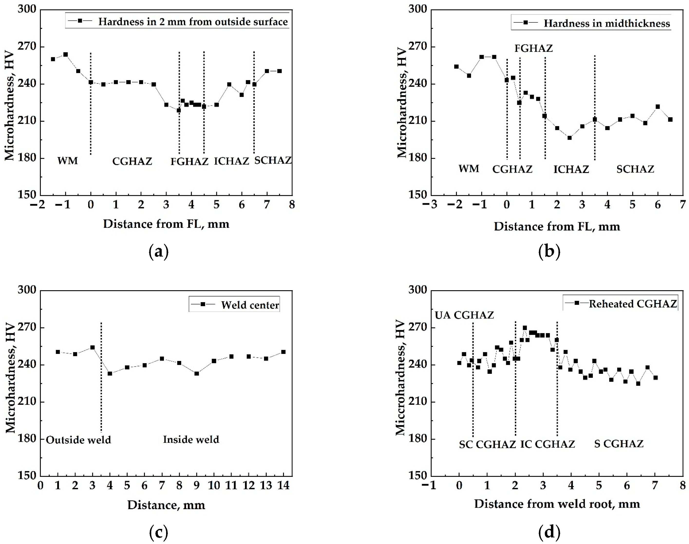
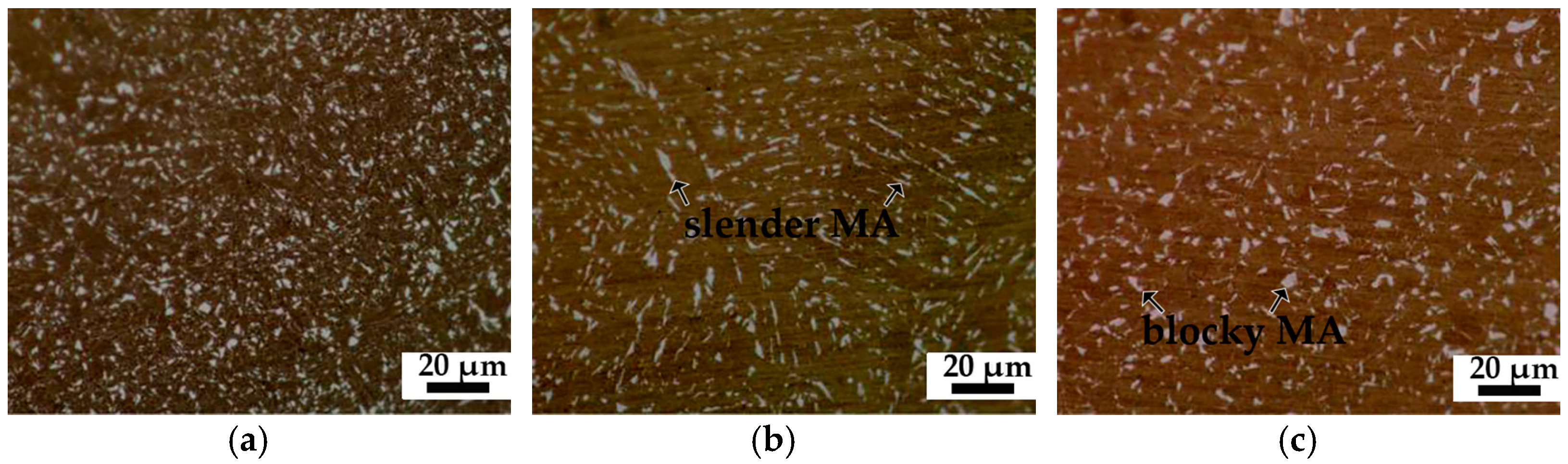
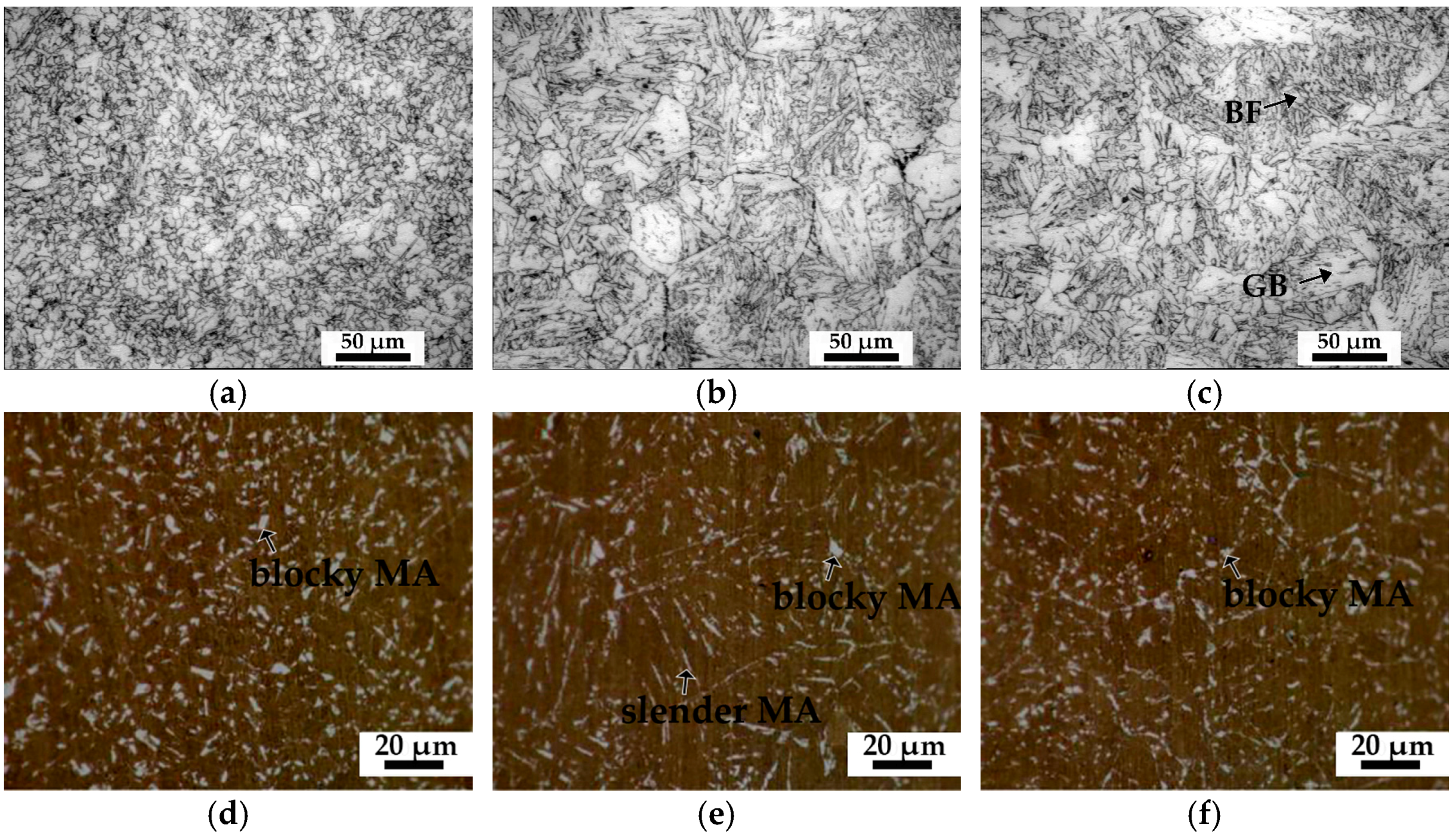
  • The BM of the pipe shows a low yield ratio of 0.83 and an excellent elongation of more than 45%. The DWTT shear area of the steel plate reaches 87%, showing excellent low-temperature toughness. IC CGHAZ shows the highest hardness within the reheated CGHAZ, with an average value of up to 262 HV. However, the concentrated blocky/slender MA constituents along the prior austenite grain boundaries of IC CGHAZ show a deteriorated impact toughness.
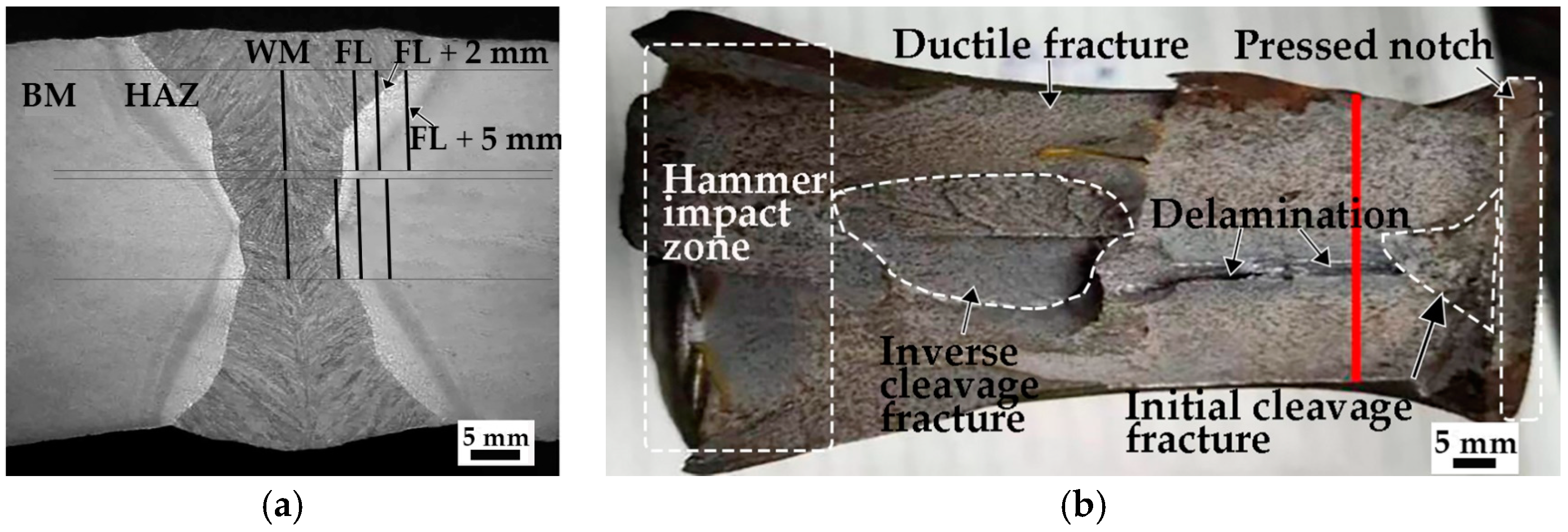
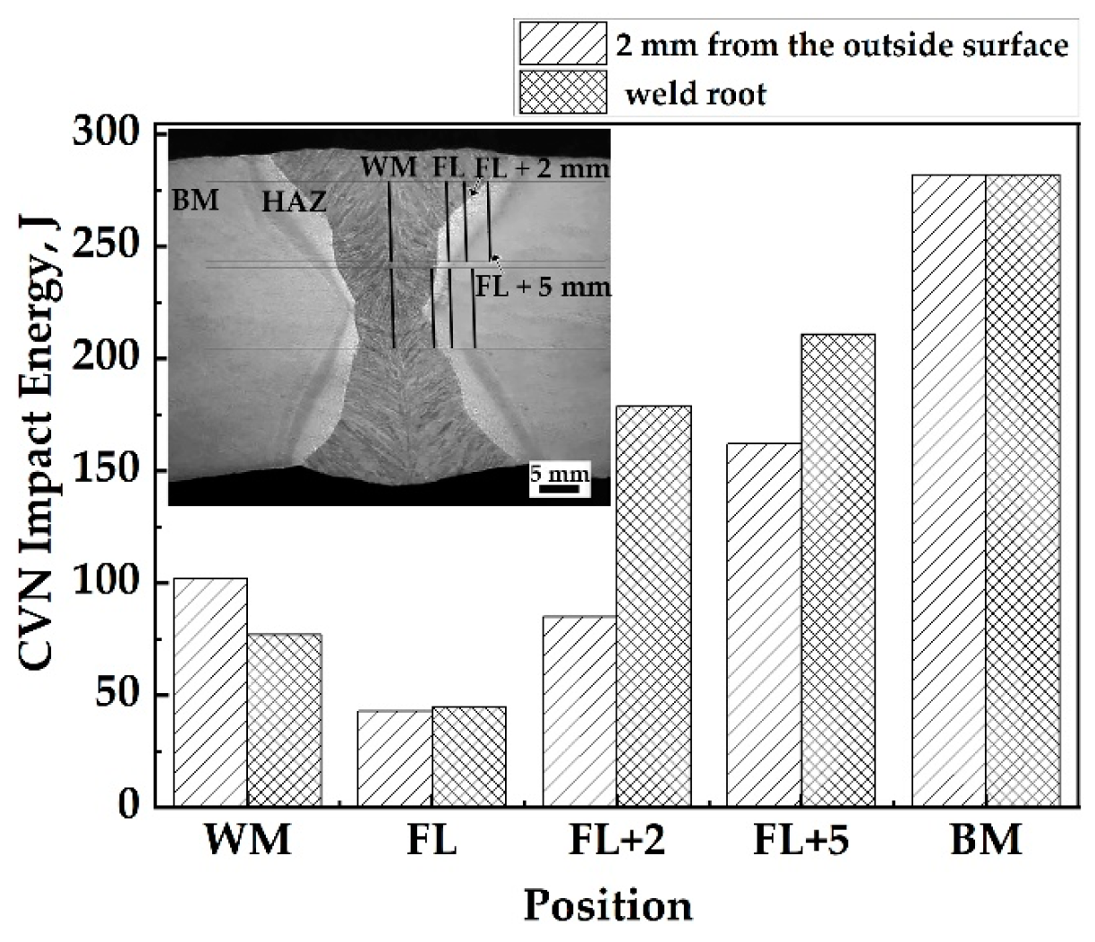
  • Under impact load, microcracks form from MA constituents. The Charpy impact energy increases as the distance away from the FL increases and reaches a maximum at the BM near HAZ due to the small size of MA constituents and grain, while that of the FL zone is the lowest just below 50 J because of two distinct microstructures, namely IAF in WM and coarse BF in CGHAZ, resulting in stress concentration in FL.
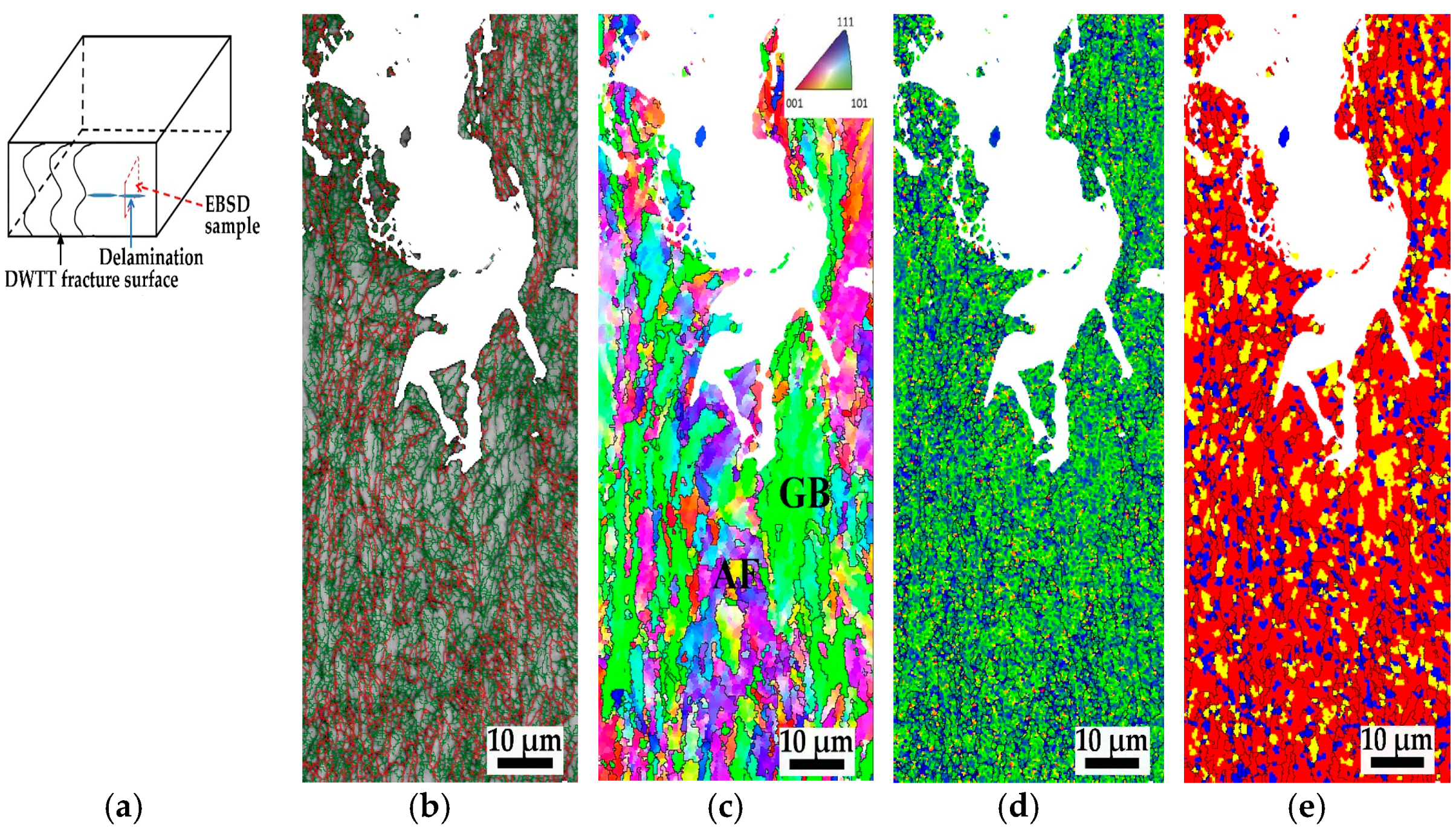
  • Delamination cracks only occurred in the midthickness of a steel plate with a small opening width, which spread about 2.1 mm perpendicular to the DWTT fracture surface. The delamination cracks were finally arrested at the AF clusters containing a high density of HAGBs. Severe stress concentration appears around the delamination cracks, and there are more substructures and deformed grains around the delamination cracks.

Author Contributions

Conceptualization, X.Z., Y.D., D.L., L.H. and J.L.; Methodology, X.Z., Y.D., D.L., L.H. and J.L.; Software and Experimental Validation, Y.D., D.L. and L.H.; Formal Analysis and Investigation, X.Z., Y.D., D.L., L.H. and J.L.; Resources, X.Z.; Data Curation, X.Z. and Y.D.; Writing—Original Draft Preparation, Y.D.; Writing—Review and Editing, X.Z.; Supervision, X.Z.; Project Administration, X.Z.; Funding Acquisition, X.Z. All authors have read and agreed to the published version of the manuscript.

Funding

This research was funded by Henan Provincial Science and Technology Cooperation Project China (grant no. 182106000016) and the Key R & D and Promotion Special Project of Henan Province (no. 212102210444).

Institutional Review Board Statement

Not applicable.

Informed Consent Statement

Not applicable.

Data Availability Statement

Data are contained within the article.

Acknowledgments

The authors gratefully acknowledge the financial support provided by Nanjing Iron & Steel Co., Ltd.

Conflicts of Interest

The authors declare no conflict of interest.

References

  1. Shin, S.Y.; Hwang, B.; Lee, S.; Kim, N.J.; Ahn, S.S. Correlation of microstructure and charpy impact properties in API X70 and X80 line-pipe steels. Mater. Sci. Eng. A 2007, 458, 281–289. [Google Scholar] [CrossRef]
  2. Hong, S.; Shin, S.Y.; Lee, S.H.; Kim, N.J. Effects of specimen thickness and notch shape on fracture modes in the drop weight tear test of API X70 and X80 linepipe steels. Metall. Mater. Trans. A 2011, 42, 2619–2632. [Google Scholar] [CrossRef] [Green Version]
  3. Li, C.W.; Wang, Y.; Chen, Y.H. Influence of peak temperature during in-service welding of API X70 pipeline steels on microstructure and fracture energy of the reheated coarse grain heat-affected zones. J. Mater. Sci. 2011, 46, 6424–6431. [Google Scholar] [CrossRef]
  4. Li, R.T.; Zuo, X.R.; Hu, Y.Y.; Wang, Z.W.; Hu, D.X. Microstructure and properties of pipeline steel with a ferrite/martensite dual-phase microstructure. Mater. Charact. 2011, 62, 801–806. [Google Scholar] [CrossRef]
  5. Yang, Y.H.; Shi, L.; Xu, Z.; Lu, H.S.; Wang, X. Fracture toughness of the materials in welded joint of X80 pipeline steel. Eng. Fract. Mech. 2015, 148, 337–349. [Google Scholar] [CrossRef]
  6. Lan, L.Y.; Qiu, C.L.; Zhao, D.W.; Gao, X.H.; Du, L.X. Microstructure characteristics and toughness of the simulated coarse grained heat affected zone of high strength low carbon bainitic steel. Mater. Sci. Eng. A 2011, 529, 192–200. [Google Scholar] [CrossRef]
  7. Huda, N.; Lazor, R.; Gerlich, A. Study of MA effect on yeild strength and ductility of X80 pipelile steels weld. Metall. Mater. Trans. A 2017, 48, 4166–4179. [Google Scholar] [CrossRef]
  8. Mohseni, P.; Solbeerg, J.K.; Karlsen, M.; Akselsen, O.M.; Østby, E. Cleavage fracture initiation at M-A constituents in intercritically coarse-grained heat-affected zone of a HSLA Steel. Metall. Mater. Trans. A 2014, 45, 384–394. [Google Scholar] [CrossRef]
  9. Di, X.J.; Cai, L.; Xing, X.X.; Chen, C.X.; Xue, Z.K. Microstructure and mechanical properties of intercritical heat-affected zone of X80 pipeline steel in simulated in-service welding. Acta Metall. Sin. 2015, 28, 883–891. [Google Scholar] [CrossRef] [Green Version]
  10. Zhu, Z.X.; Kuzmikova, L.; Li, H.J.; Barbaro, F. Effect of inter-critically reheating temperature on microstructure and properties of simulated inter-critically reheated coarse grained heat affected zone in X70 steel. Mater. Sci. Eng. A 2014, 605, 8–13. [Google Scholar] [CrossRef]
  11. Moeinifar, S.; Kokabi, A.H.; Madaah Hosseini, H.R. Role of tandem submerged arc welding thermal cycles on properties of the heat affected zone in X80 microalloyed pipe line steel. J. Mater. Process. Technol. 2011, 211, 368–375. [Google Scholar] [CrossRef]
  12. DNV-OS-F101; Offshore Standard Submarine Pipeline Systems. Det Norske Veritas: Bærum, Norway, 2013; pp. 140–187.
  13. Zhao, J.; Hu, W.; Wang, X.; Kang, J.; Yuan, J.; Di, H.; Misra, R.D.K. Effect of microstructure on the crack propagation behavior of microalloyed 560 MPa (X80) strip during ultra-fast cooling. Mater. Sci. Eng. A 2016, 666, 214–224. [Google Scholar] [CrossRef]
  14. Yuan, G.; Hu, W.; Wang, X.; Kang, J.; Zhao, J.; Di, H.; Misra, R.D.K.; Wang, G. The relationship between microstructure, crystallographic orientation, and fracture behavior in a high strength ferrous alloy. J. Alloys Comp. 2017, 695, 526–539. [Google Scholar] [CrossRef]
  15. Shukla, R.; Ghosh, S.K.; Chakrabarti, D.; Chatterjee, S. Microstructure, texture, property relationship in thermo-mechanically processed ultra-low carbon microalloyed steel for pipeline application. Mater. Sci. Eng. A 2013, 587, 201–208. [Google Scholar] [CrossRef]
  16. Andrews, K. Empirical formulae for the calculation of some transformation temperatures. J. Iron Steel Inst. 1965, 203, 721–727. [Google Scholar]
  17. Xiong, Z.H.; Liu, S.L.; Wang, X.M.; Shang, C.J.; Li, X.C.; Misra, R.D.K. The contribution of intragranular acicular ferrite microstructural constituent on impact toughness and impeding crack initiation and propagation in the heat-affected zone (HAZ) of low-carbon steels. Mater. Sci. Eng. A 2015, 636, 117–123. [Google Scholar] [CrossRef]
  18. Xiao, F.R.; Liao, B.; Shan, Y.Y.; Qiao, G.Y.; Zhong, Y.; Zhang, C.L.; Yang, K. Challenge of mechanical properties of an acicular ferrite pipeline steel. Mater. Sci. Eng. A 2006, 431, 41–52. [Google Scholar] [CrossRef]
  19. Zhao, M.C.; Yang, K. Effects of nano-sized microalloyed carbonitrides and high-density pinned dislocations on sulfide stress cracking resistance of pipeline steels. J. Mater. Res. 2005, 20, 2248–2251. [Google Scholar] [CrossRef]
  20. Bataev, I.A.; Bataev, A.A.; Burov, V.G.; Lizunkova, Y.S.; Zakharevich, E.E. Structure of widmanstatten crystals of ferrite and cementite. Steel Transl. 2008, 38, 684–687. [Google Scholar] [CrossRef]
  21. Sun, X.J.; Yuan, S.F.; Xie, Z.J.; Dong, L.L.; Shang, C.J.; Misra, R.D.K. Microstructure-property relationship in a high strength-high toughness combination ultra-heavy gauge offshore plate steel: The significance of multiphase microstructure. Mater. Sci. Eng. A 2017, 689, 212–219. [Google Scholar] [CrossRef]
  22. Huda, N.; Midawi, A.R.H.; Gianetto, J.; Lazor, R.; Gerlich, A.P. Influence of martensite-austenite (MA) on impact toughness of X80 line pipe steels. Mater. Sci. Eng. A 2016, 662, 481–491. [Google Scholar] [CrossRef]
  23. Moeinifar, S.; Kokabi, A.H.; Madaah, H.H.R. Influence of peak temperature during simulation and real thermal cycles on microstructure and fracture properties of the reheated zones. Mater. Des. 2010, 31, 2948–2955. [Google Scholar] [CrossRef]
  24. Yakubtsov, I.A.; Poruks, P.; Boyd, J.D. Microstructure and mechanical properties of bainitic low carbon high strength plate steels. Mater. Sci. Eng. A 2008, 480, 109–116. [Google Scholar] [CrossRef]
  25. Gervasyev, A.; Pyshmintsev, I.; Petrov, R.; Huo, C.Y.; Barbaro, F. Splitting susceptibility in modern X80 pipeline steels. Mater. Sci. Eng. A 2020, 772, 138746. [Google Scholar] [CrossRef]
  26. Li, X.D.; Ma, X.P.; Subramanian, S.V.; Shang, C.J. EBSD characterization of secondary microcracks in the heat affected zone of a X100 pipeline steel weld joint. Int. J. Fract. 2015, 193, 131–139. [Google Scholar] [CrossRef]
  27. Yang, X.L.; Xu, Y.B.; Tan, X.D.; Wu, D. Relationships among crystallographic texture, fracture behavior and Charpy impact toughness in API X100 pipeline steel. Mater. Sci. Eng. A 2015, 641, 96–106. [Google Scholar] [CrossRef]
  28. Sha, Q.Y.; Li, D.H. Microstructure, mechanical properties and hydrogen induced cracking susceptibility of X80 pipeline steel with reduced Mn content. Mater. Sci. Eng. A 2013, 585, 214–221. [Google Scholar] [CrossRef]
Figure 1. Schematic diagram of welded joint. The abbreviations in the figure are explained as follows: the base metal zone (BM), the coarse grain heat-affected zone (CGHAZ), the fine grain HAZ (FGHAZ), the intercritical HAZ (ICHAZ) and the subcritical HAZ (SCHAZ), unaltered CGHAZ (UA CGHAZ), supercritically reheated CGHAZ (SC CGHAZ), intercritically reheated CGHAZ (IC CGHAZ) and subcritically reheated CGHAZ (S CGHAZ).
Metals 12 00716 g001
Figure 2. Macromorphology of the welded joint (a); and DWTT fracture surface (b).
Metals 12 00716 g002
Figure 3. Hardness distribution of the welded joint in different regions. (a) 2 mm from outside surface; (b) midthickness; (c) WM center; (d) reheated CGHAZ.
Metals 12 00716 g003
Figure 4. SEM images of the welded joint. (a) FL; (b) FGHAZ; (c) ICHAZ; (d) SCHAZ; (e) weld center at 2 mm away from the outside weld surface; (f) weld center in midthickness.
Metals 12 00716 g004aMetals 12 00716 g004b
Figure 5. OM images showing the distribution and morphology of MA constituents in different regions. (a) WM; (b) CGHAZ; (c) FGHAZ; (d) ICHAZ; (e) SCHAZ.
Metals 12 00716 g005aMetals 12 00716 g005b
Figure 6. OM images showing the microstructure and MA constituents of the reheated CGHAZ. (a,d) SC CGHAZ; (b,e) IC CGHAZ; (c,f) S CGHAZ.
Metals 12 00716 g006
Figure 7. Charpy impact energy of the welded joint notched in different regions.
Metals 12 00716 g007
Figure 8. Microstructure near the tip of the delamination crack. (a) Low-magnification SEM micrograph; (b) high-magnification SEM micrograph.
Metals 12 00716 g008
Figure 9. Schematic diagram of EBSD sampling location (a) and EBSD analysis diagrams with {001} plane around the tip of delamination crack; (b) image quality plus grain boundary misorientation map; (c) color-coded inverse pole figure plus grain boundary misorientation map (black line, >15°); (d) kernel average misorientation map; (e) distribution map of deformed grains, recrystallized grains and substructures.
Metals 12 00716 g009
Table 1. Tensile properties of the pipe.
SpecimenParameterSingle ValueMean ValuesStandard Deviation
123
Base metal (T)Yield strength (MPa)53555753454213.0
Tensile strength (MPa)6506606416509.5
Yield ratio0.820.840.830.830.010
Elongation (%)474842463.21
Base metal (L)Yield strength (MPa)5365295255305.6
Tensile strength (MPa)6466336406406.5
Yield ratio0.830.840.820.830.010
Elongation (%)464345451.53
Weld metal (L)Yield strength (MPa)65064163064010.0
Tensile strength (MPa)7307187137208.7
Yield ratio0.890.890.880.890.006
Elongation (%)403547416.03
Note: L is longitudinal; T is transverse.
Table 2. Average size and volume fraction of MA constituents in different regions.
RegionWMCGHAZFGHAZICHAZ
Average size (μm)1.281.841.741.70
Volume fraction (%)4.365.465.264.59
Publisher’s Note: MDPI stays neutral with regard to jurisdictional claims in published maps and institutional affiliations.

