Article

Influence of ICCGHAZ on the Low-Temperature Toughness in HAZ of Heavy-Wall X80 Pipeline Steel

1
College of New Energy, China University of Petroleum (East China), Qingdao 266580, China
2
Shandong Institute of Petroleum and Chemical Technology, Dongying 257061, China
3
School of Materials Science and Engineering, China University of Petroleum (East China), Qingdao 266580, China
4
PipeChina West East Gas Pipeline Company, Shanghai 200122, China
*
Author to whom correspondence should be addressed.
Metals 2022, 12(6), 907; https://doi.org/10.3390/met12060907
Submission received: 18 April 2022 / Revised: 15 May 2022 / Accepted: 23 May 2022 / Published: 26 May 2022
(This article belongs to the Special Issue Advances in High-Strength Low-Alloy Steels)

Abstract

:
Low-temperature embrittlement in the heat-affected zone (HAZ) of heavy-wall X80 weld joints is a primary challenge for arctic oil & gas exploitation. In this paper, the influence of intercritically reheated coarse-grained HAZ (ICCGHAZ) on the low-temperature toughness of the weld joint in a 22 mm thick X80 spiral submerged arc welded pipe was studied through instrumented Charpy V-notch impact test at −80~20 °C and corresponding fracture surface characterization. The results indicated that the influence of ICCGHAZ on the overall toughness of the weld joint is related to temperature. At temperatures below −45 °C, individual and tiny martensite-austenite (MA) constituent debonding can trigger cleavage fracture–which was proved to be nucleation-controlled–and the probability of embrittlement of the ICCGHAZ increases. At temperatures higher than −45 °C, only relatively large or closely distributed MA constituent in ICCGHAZ satisfies the conditions to trigger propagation-controlled cleavage fractures, and the influence of ICCGHAZ on the overall toughness is not remarkable.

1. Introduction

Approximately 13% of undiscovered oil and 30% of undiscovered natural gas resources are stored in Arctic regions [1]. Pipelines are the most convenient form of transportation to exploit Arctic gas and oil [2]. Extremely low service temperatures as low as −60 °C will result in the embrittlement of the pipeline steel, which is one of the primary challenges to building an Arctic pipeline [3]. Previous studies have indicated that heavy-wall X80 steel rolled by a series of particular production technologies has excellent low-temperature toughness, which is the preferred material for Arctic pipelines [4,5,6,7]. However, after the steel is manufactured into pipes by dual-pass submerged arc welding, the toughness in the heat-affected zone (HAZ) of the weld joint will deteriorate, especially in intercritically reheated coarse grain HAZ (ICCGHAZ); this is a small region where the coarse grain HAZ (CGHAZ) of the first welding pass is reheated to the intercritical temperature (AC1~AC3) by the second welding pass. Previously, the toughness of ICCGHAZ via thermal simulation test was extensively studied, and was proved to be a local brittle zone (LBZ) [8,9]. For example, Moeinifar and Andia reported that the Charpy impact energy of ICCGHAZ simulated by different thermal cycles are all below 20 J at −60 °C, respectively [10,11]. Meanwhile, the local brittle mechanism has been clarified, which is associated with the hard and brittle MA constituent distributed along the coarsened prior austenite grains boundary (PAGB) [12,13,14].
However, few studies have focused on how ICCGHAZ affects the overall toughness of the weld joint, especially at temperatures below −60 °C. Low-temperature pipelines are generally designed with large pipe diameters and heavy wall thicknesses, such as the Bovanenkovo–Ukhta (B-U) pipeline that uses 23 mm K65 (API grade X80) steel, requiring a Charpy impact toughness in HAZ not less than 56 J at −40 °C [15]. For heavy-wall X80 pipeline steel, ICCGHAZ is only a very small subzone located in the middle of the wall thickness. According to most current standards, such as the standard API SPEC 5L, ISO 3183, and the technical specification of B-U pipeline, the impact test specimens are taken as close as practicable to the outer surface of the pipe. However, the tested specimen most likely does not contain ICCGHAZ, which means the influence of ICCGHAZ is ignored. For the safety of heavy-wall arctic pipelines, it is essential to evaluate the influence of ICCGHAZ on the toughness of the whole weld joint.
The present study fabricated a 22 mm thick X80M weld joint by spiral submerged arc welding (SSAW). The microstructure of different subzones in the HAZ was studied. The instrumented Charpy V-notch impact test was applied at a series of temperatures with the notch across the ICCGHAZ. The macroscopic fracture surface and the microscopic cleavage crack nucleation and propagation were investigated in detail to clarify how and why the ICCGHAZ affects the low-temperature toughness of overall HAZ.

2. Materials and Methods

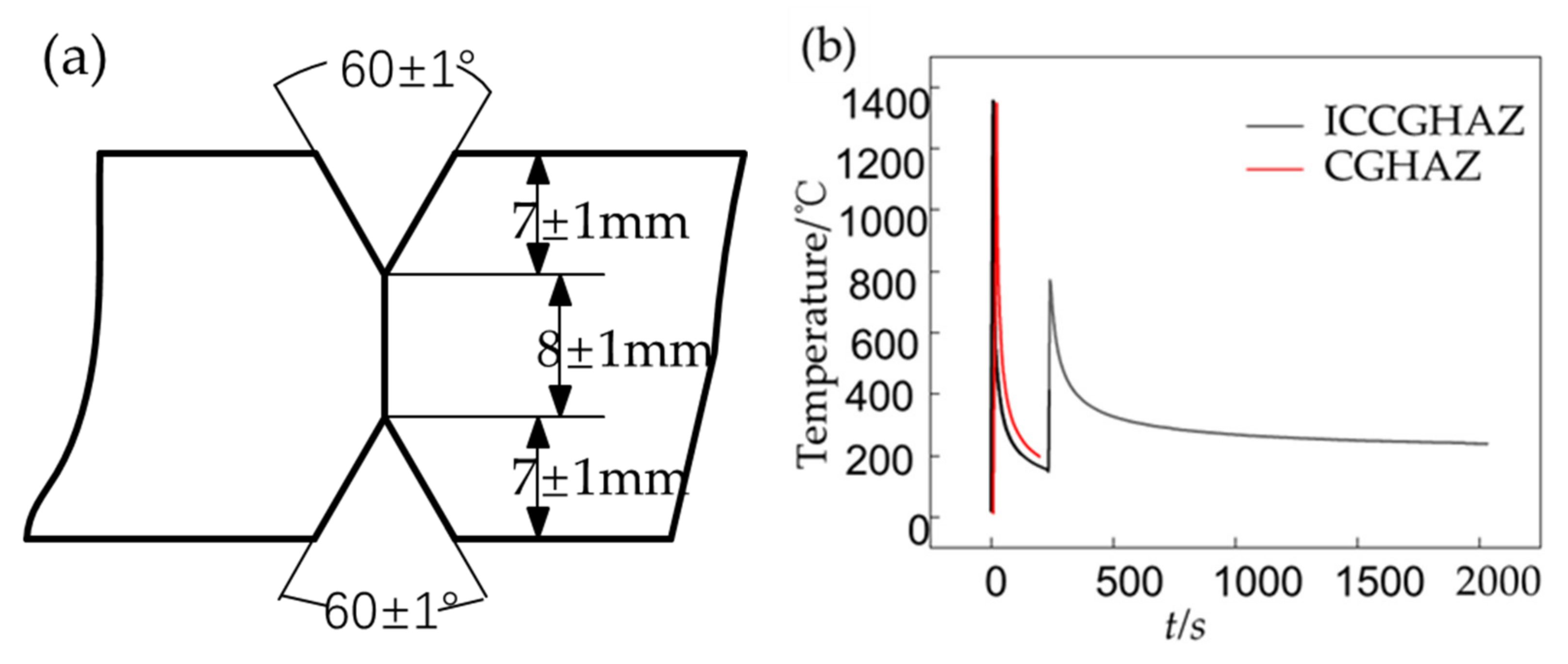
2.1. Materials and Welding Processes

The 22 mm thick X80M steel in this paper is rolled for the China-Russia East natural gas pipeline stations using thermo-mechanical controlled process (TMCP). The chemical composition was determined by optical emission spectrometer, as listed in Table 1. The steel was manufactured to 1422 mm outer diameter pipes by two tandem SSAW wires from the inside and outside. The groove of the weld joint is shown in Figure 1a. Detailed welding parameters are listed in Table 2.
The thermal simulated ICCGHAZ and CGHAZ were prepared to obtain a similar microstructure to the corresponding subzone in actual HAZ, and hence to reveal the individual toughness of the small subzones. Samples with dimensions of 11 × 11 × 55 mm3 were cut from the pipe body along the rolling direction and subjected to thermal cycles (Figure 1b) to simulate CGHAZ and ICCGHAZ, via a Gleeble 3800 machine.

2.2. Impact Toughness Test and Fractography Analysis

The impact toughness was evaluated by the instrumented impact test according to the API SPEC5L standard. The samples were taken from the pipe, then etched in 4% nital solution to precisely locate the axis of the V-notch, and finally machined into the standard dimension (10 × 10 × 55 mm3). The simulated samples were also machined into the standard dimension. The notch for the standard HAZ (the yellow rectangle in Figure 2a) passed through the intersection of the fusion line and the outer surface as close as practicable, marked as Group HI. Samples of Group HII were taken from 4 mm below the outer surface (the red rectangle in Figure 2a), and the detail of the notch location was shown in Figure 2b. The notch in Group HII will encounter CGHAZ, fine grain HAZ (FGHAZ), and ICCGHAZ, while CGHAZ, FGHAZ, and intercritical HAZ (ICHAZ) are encountered in Group HI.
The impact test was performed at 20, 0, −20, −30, −45, −60, and −80 °C, respectively. The temperature of −45 °C is the test temperature of the China-Russia East natural gas pipeline technical specification.
After the impact test, the fracture surfaces were characterized under stereomicroscope and scanning electron microscopy (SEM).

2.3. Microstructural Characterization

The microstructure of different subzones in the weld joint was analyzed by optical microscopy (OM) and SEM. LePera solution was used to reveal the characteristic of MA constituent [16,17].

3. Results and Discussion
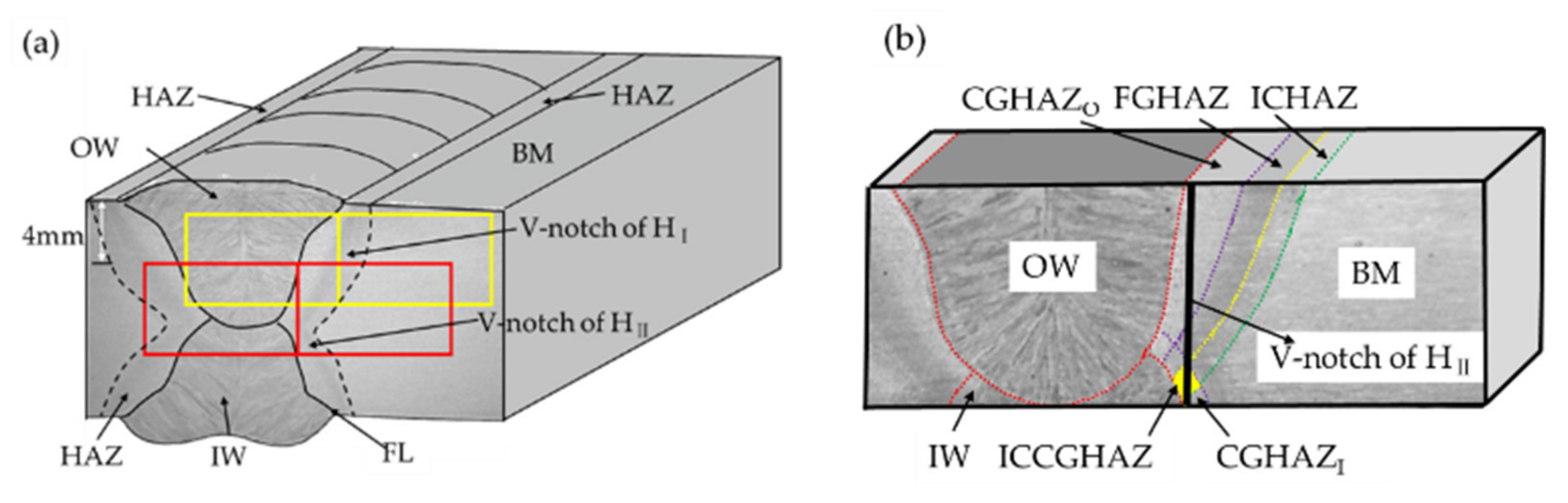
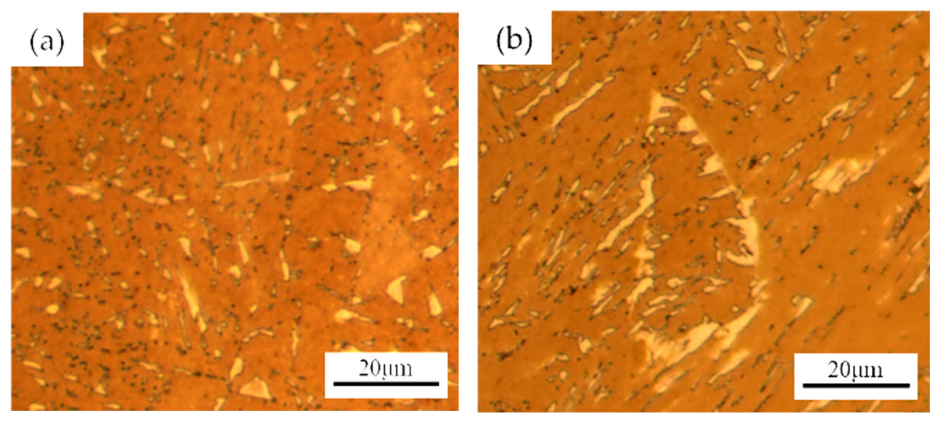
3.1. Microstructure

The microstructure of different regions in the weld joint is presented in Figure 3. The microstructure of base metal (Figure 3a) consists of granular bainite (GB) with tiny MA constituent (about 1–2 μm) dispersed in it. This microstructure enables the excellent low-temperature toughness of base metal [18]. The main microstructure of FGHAZ (Figure 3b) is refined polygonal ferrite and quasi-polygon ferrite with granular MA constituent. The mean grain size of FGHAZ is about 5 μm. In CGHAZ (Figure 3c), the average grain size is about 60 μm. The prior austenite grain is divided into several packets by different orientations of bainitic ferrite (BF) or GB. The lath of BF grows from the prior austenite grain boundary (PAGB) into the internal, and between them is slender MA constituent film (as long as about 10 to 15 μm). In contrast, the MA constituent in GB is granular or blocky.
The matrix microstructure and grain size of ICCGHAZ (Figure 3d) is similar to CGHAZ. The significant difference is the shape, size, and fraction of the MA constituent. This is because part of the matrix in ICCGHAZ reverts to austenite during the reheating stage, and PAGB is the preferred nucleation site for reverted structure. Then, the reverted austenite transforms into MA constituent and bainite, etc. Therefore, the MA constituent in ICCGHAZ has a preferred location on PAGB with a “necklace-type” [19,20,21]. Nevertheless, only a small amount of MA constituent is distributed along PAGB in CGHAZ. As shown in Figure 4, the white blocky and slender microstructure is MA constituent via LePera solution etched. The MA constituent in ICCGHAZ is larger in size, higher in fraction, and more preferential to form a necklace distribution on PAGB than in CGHAZ.
Additionally, Figure 3e,f indicate that the microstructures in thermal-simulated CGHAZ and ICCGHAZ are basically the same as the actual CGHAZ and ICCGHAZ, respectively.

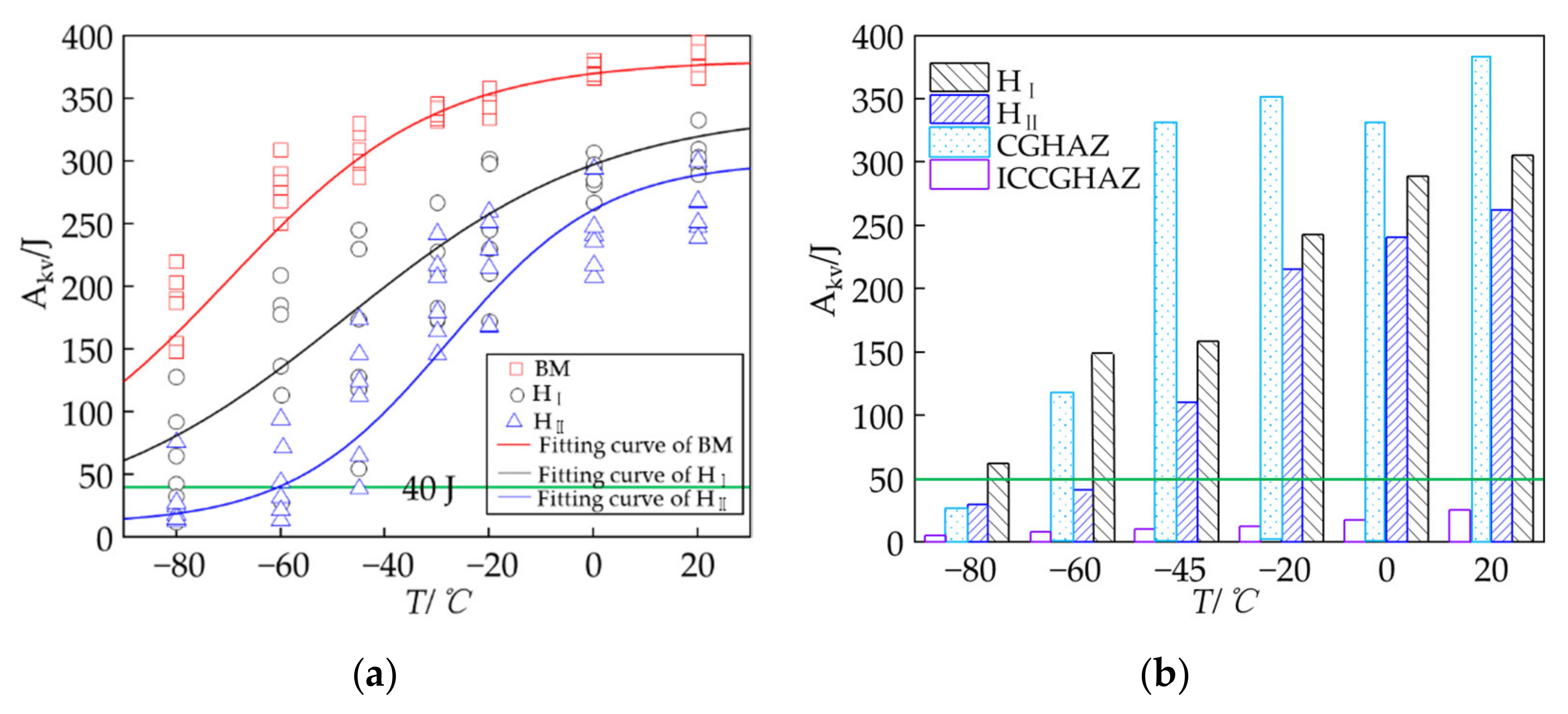
3.2. Impact Toughness and Fractography Characterization

The single and average impact absorbed energy (Akv) of different regions as a function of test temperature is shown in Figure 5. The ductile–brittle transition curves were fitted by the Boltzmann formula. The ductile–brittle transition temperature (DBTT) is defined as the temperature corresponding to 50 percent of the upper and lower shelf energy, abbreviated as ETT50 [22,23]. The primary curves information is given in Table 3. The green lines (Akv = 40 J in Figure 5a and Akv = 50 J in Figure 5b) are the accepted minimum single and mean value in the China-Russia East natural gas pipeline technical specification, respectively. In this paper, if the single value is smaller than 40 J, this sample is defined as a brittle sample. Meanwhile, if the mean value of samples at certain temperature is smaller than 50 J, the tested region is defined as a brittle region at this temperature.
The base metal has excellent low-temperature toughness. The lower shelf energy is 50 J and the ductile–brittle transition temperature (DBTT) is −78.5 °C. For Group HI, every single and mean Akv value is larger than 40 J and 50 J at temperatures higher than −60 °C, respectively. Even at −80 °C, the mean Akv value is still larger than 50 J, and only two samples are brittle. In short, the standard HAZ has good low-temperature toughness. Conversely, the toughness of Group HII deteriorates. At temperatures higher than −45 °C, the mean values are between 190 J to 270 J, and about 50 J smaller than Group HI. The minimum single value is 146 J. Both the single and mean values are not the brittle value. At −45 °C, although the mean value is higher than 100 J, a brittle value of 39 J is presented. At −60 °C, the mean value 47 J is about 100 J smaller than for Group HI, and most of the samples are brittle with a minimum value of 14 J. Of note, at −80 °C, only one sample is larger than 40 J, and the mean value is only 29 J, while it is still higher than 50 J in Group HI. The present results indicate that the influence of ICCGHAZ is temperature-dependent, and the critical temperature is −45 °C. Additionally, the DBTT of Group HII is significantly higher than Group HI. DBTT of HI is −47.5 °C, while HII is −28 °C.
Previous study reported that Charpy impact energy is the average of subzones across the V-notch and is dominated by the most brittle region [19]. As shown in Figure 5b, the toughness of simulated CGHAZ is better than the other zone. The simulated ICCGHAZ with Akv values no larger than 25 J is the most brittle region. However, at temperatures higher than −45 °C, ICCGHAZ does not result in the overall HAZ embrittlement. At −45 °C, brittle samples begin to present for Group HI, while the embrittlement temperature for Group HII is −60 °C. At temperatures below −45 °C, the existence of ICCGHAZ will promote embrittlement remarkably. Therefore, the standard HAZ impact test cannot comprehensively represent the toughness of the overall HAZ. The influence of ICCGHAZ cannot be ignored for arctic pipelines running at temperatures below −45 °C.
The load-displacement curves of the instrument impact test at different temperatures are presented in Figure 6b, and the corresponding macroscopic fracture morphology is presented in Figure 7. The impact absorbed energy is comprised of the energy of four different stages, which correspond to the different regions on the fracture surface: the stretch zone, the ductile zone, the brittle zone, and the shear lip. The stretch zone is related to the stage of elastic deformation, plastic deformation, and deformation strengthening before the maximum load is reached [24]. The corresponding energy is the crack initiation energy, Wi, which is similar at −60 to 0 °C. The stable crack propagation corresponds to the ductile zone with the Wp1 energy. Once the brittle crack is initiated, the unstable crack rapidly propagates, forming the brittle zone that is correlated with the Wp2 energy. The shear lip occupies a small region of the fracture, and the area decreases as the temperature decreases. The existence of the shear lip contributes to the Wp3 energy. The absorbed energy is equal to Wi + Wp1 + Wp2 + Wp3.
At 0 °C, the fracture surface is about 70 pct. ductile and 30 pct. brittle, and accordingly, there is a long displacement of stable crack propagation with a very large energy Wp1. At −45 °C, the ductile zone remains about 40 pct., Wp1 decreases remarkably, while Wi, Wp2, and Wp3 remain basically unchanged. When the temperature decreases to −60 °C, the ductile zone is only about 15 pct., Wi remains unchanged, the energy Wp1 and Wp2 are both very small, and Wp3 is 0. At −80 °C, the fracture surface is 97 pct. brittle with the energy Wp1 almost 0. Once the maximum load is reached, the brittle cracks initiate and rapidly propagate to the entire fracture.
The above results indicate that the stable crack propagation energy Wp1 decreased remarkably, while the others (Wi, Wp2, and Wp3) were less influenced by the decreasing temperatures. The Wp1 energy is controlled by the brittle crack initiation. In other words, the later the brittle crack initiates, the larger the Wp1 and the impact energy is. Therefore, it is essential to identify the brittle crack initiation.

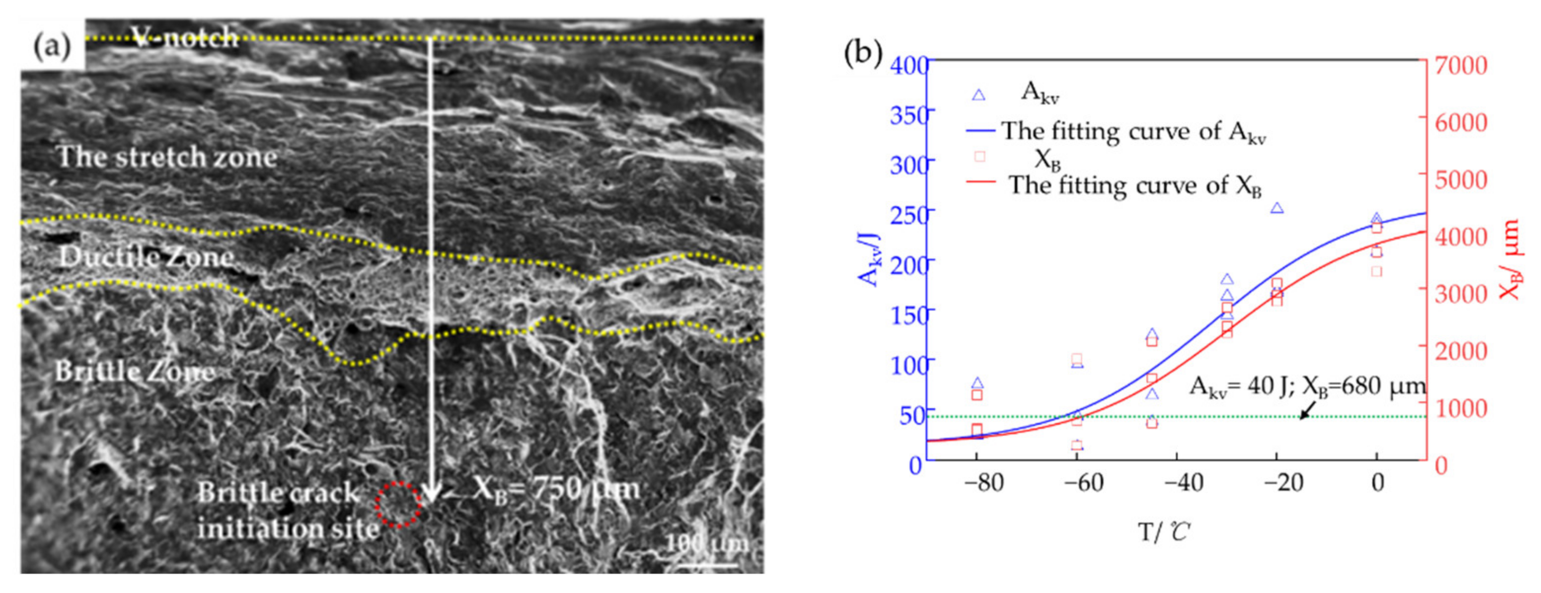
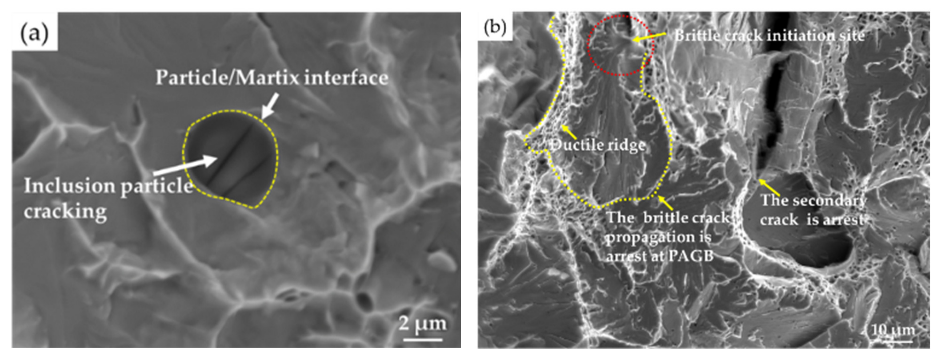
3.3. The Brittle Crack Initiation Analysis

The typical brittle crack initiation sites of Group HII at different temperatures are identified by SEM, presented in Figure 8. The typical river line patterns indicate the initiation sites marked by arrows 1 to 6.
The brittle crack initiation sites are significantly different at temperatures above or below −45 °C. At −80 °C, the initiations site is an irregular particle as small as 1 μm (marked by arrows 1 in Figure 8a) and forms a hole (marked by arrow 2 in Figure 8b) in the corresponding position of the matching fracture surface. EDS measurement did not reveal any differences between the particle and the matrix. Based on the blocky type appearance of the particle, it is considered to be MA constituent. Therefore, the brittle crack initiation mechanism is debonding of MA constituents from the surrounding bainite matrix, as previous research reported [25]. At −60 °C, the initiation sites of two different samples are marked by arrows 3 and 4 in Figure 8c,d, respectively. They are also related to the individual MA constituent debonding. The size of the MA constituent that can promote the brittle crack initiation is as small as 1 to 3 μm. At −45 °C and higher temperatures, the crack sites are preferentially located around large sizes or closely distributed MA constituent, as shown in Figure 8e,f. Previous studies have indicated that closely distributed MA constituent can result in local constrained high stress fields and trigger microcracks [26,27,28]. As presented in Figure 3d, the necklace-type MA constituent distributing on PAGB and high fractions in ICCGHAZ satisfy this condition. Thus, the brittle crack initiations are located in ICCGHAZ at temperature higher than −45 °C. Conversely, at temperature below −45 °C, a single, small MA constituent, whether in ICCGHAZ or CGHAZ, can initiate a brittle cleavage crack.
Along with the identification of the brittle crack initiation sites, the distance between the crack initiation sites and the V-notch tip was also measured. Taking the brittle crack initiation site in Figure 7d as an example, the distance (denoted as XB) was measured at low magnification (Figure 9a). The relationship between Akv and corresponding XB values at different temperatures are presented in Figure 9b. The fitting curves of the Akv and XB values correlate with each other well. At temperatures higher than −45 °C, all the XB values are larger than 2300 μm, while all the Akv values are larger than 150 J. At −45 °C, there is one Akv value smaller than 40 J, and the corresponding XB value is 642 μm. At temperatures below −45 °C, four Akv values are smaller than 40 J, while the corresponding XB values are smaller than 680 μm. The lower shelf platform energy is about 15 J, and meanwhile, the distance XB is about 250 μm. The XB values tend to be smaller than 680 μm at temperatures below −45 °C, and conversely larger than 680 μm at temperatures higher than −45 °C. Griffiths and Owen have indicated that the maximum stress occurs from about 1~3 times the root radius of the V-notch [29]. In the present case, the root radius is 0.25 mm and the distance of maximum stress (DMS) from the notch tip is expected to be 250~750 μm. Thus, 680 μm is in this interval and assumed as the DMS, which corresponds to the Akv value 40 J. Previous research has reported that when the XB is smaller than DMS, brittle cracks are nucleation control, or propagation control [30]. Therefore, the critical temperature for nucleation and propagation control transformation for Group HII is −45 °C.

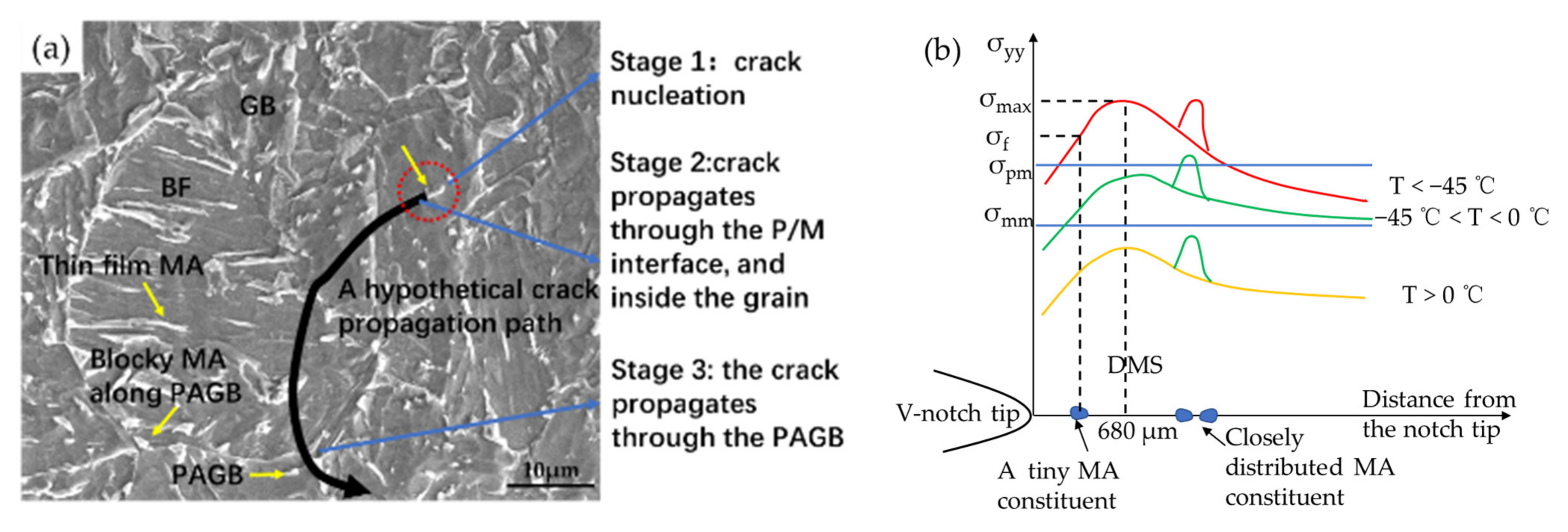
3.4. The Influence Mechanism of ICCGHAZ on HAZ at Low Temperature

The above results are concluded in Table 4. Obviously, −45 °C is the critical temperature for the influence of ICCGHAZ on the overall HAZ. To interpret the above phenomenon, the three stages of cleavage fracture formation were analyzed as shown in Figure 10. In stage one, the brittle crack nucleated due to the debonding of blocky MA constituent. In stage two, this microcrack propagated into the bainite matrix across the MA/matrix interface. Then, the crack continued propagating inside the grain, passing through different orientations of BF, GB, or MA constituent. It can be hindered or deflected by the second phase/matrix (P/M) boundary, especially the high-angle bainite Bain packet or the different orientations of BF and GB [31,32,33]. In stage three, the brittle crack propagated through the PAGB into the surrounding grains, eventually generating a macroscopic brittle fracture. If any one of the three stages is hindered, the cleavage fracture will not occur.
The stress states ahead of the notch tip during loading were analyzed combined with the cleavage stages, and the normal stress (σyy) as a function of the distance from the notch tip at different temperatures is schematically presented in Figure 10b. The maximum normal stress (σmax) can be intensified by 2.3~5 times compared to the yield stress (σy). The σy of the material increases with a decrease in temperature. The stress at the Particle/Matrix (P/M) interface (σpm) and the PAGB (σmm) is in accordance with Equations (1) and (2) [34].
σ pm = π E γ pm a 1 ν 2 1 2 ,
σ mm = π E γ mm D 1 ν 2 1 2 ,
E represents elastic modulus; ν represents Poisson’s ratio; a and D represent the second phase diameter and the grain size; γpm and γmm represent fracture surface energy. Obviously, the smaller the second phase diameter and the grain size, the higher the σpm and σmm. The influence of temperature on the above stress affecting brittle crack nucleation and propagation is illustrated in Figure 10b.
At low temperatures (below −45 °C), the normal stress σf is larger than the stress σpm at tiny MA constituent/matrix interfaces at a distance smaller than DMS. Therefore, either small or large MA constituent debonding in the front of the notch tip can trigger brittle cracks. Once a brittle crack has nucleated, it could result in a whole brittle fracture; the fracture is nucleation-controlled. Furthermore, large or closely distributed MA constituent in ICCGHAZ more easily promotes brittle crack nucleation. Meanwhile, the large MA/matrix interface and the PAGB with necklace-type MA constituent can promote crack propagating into other grains more easily. The crack initiation energy Wi as well as the crack propagation energy Wp1 + Wp2 are low. Consequently, ICCGHAZ can decrease the overall toughness by providing more potential sources of brittle crack initiation and promoting crack propagation.
At moderately low temperatures (0~−45 °C), the intensified σyy will decrease with increasing temperatures, which results in σmmyy< σpm. The evidence is that a cracked inclusion (~3μm, Figure 11b) was observed at the surface, but the crack was hindered by the interface marked by the yellow broken line, which denotes that σpm is larger than σmax. Therefore, the single and small brittle second phase makes it hard to trigger cleavage cracks. In contrast, it could be easier to achieve larger σyy at some large-sized MA constituent interfaces, and when σyy > σpm, the debonding of MA constituent or the cracking of inclusion can trigger brittle crack nucleation and propagation. On the other hand, due to local stress concentration, the stress σyy at closely distributed MA constituents is more likely to be larger than σpm and σmm. Therefore, a stable crack propagation stage exists before the cleavage crack nucleates, and the fracture is propagation-controlled. The MA constituent in ICCGHAZ is either large in size or closely distributed, and hence the brittle crack initiation sites are more preferentially located in ICCGHAZ. However, due to the large energy Wp1, the ICCGHAZ will not significantly decrease the overall toughness.
At higher temperatures (0~20 °C), the σyy are not sufficient to promote cracks across the P/M interface, the bainite packet, and the grain boundaries. As shown in Figure 11b, there is a brittle crack initiation marked in the red circle, however, the propagation is arrest at PAGB by the ductile ridge. Therefore, the fracture shows more ductile features, and the overall HAZ has excellent toughness.

4. Conclusions

The influence of ICCGHAZ on the low-temperature toughness in the HAZ of 22 mm thick X80M weld joint was studied in this paper. The major conclusions are summarized as follows:
(1)
The influence of ICCGHAZ on the overall toughness is temperature-dependent. At temperatures higher than −45 °C, the toughness of ICCGHAZ decreases to a limited extent and will not result in embrittlement. Only at temperatures below −45 °C does ICCGHAZ play an obvious role in decreasing the overall toughness. For pipelines serving below −45 °C, influence of ICCGHAZ on low temperature toughness of the whole weld joint should be considered.
(2)
The influence of ICCGHAZ is particularly associated with its microstructure. The MA constituent in ICCGHAZ is larger in size, higher in fraction, and more likely to form necklace-like distribution on PAGB. These characteristics contributes to MA as a potential site of brittle initiation.
(3)
The embrittlement mechanism of ICCGHAZ is associated with the three stages of cleavage fracture formation, which are related to the characteristic of MA constituent and temperature. At extremely low temperatures (below −45 °C), the fracture is nucleation-controlled. Single and small MA constituents can initiate a brittle crack. Once it nucleates, the second particle/matrix interface and the PAGB cannot hinder the propagation. The brittle crack initiation sites can be located in either ICCGHAZ or CGHAZ; at moderately low temperatures (−45~0 °C), the MA constituent with large size or close distribution meets the cleavage crack initiation and propagation conditions. The initiation sites are preferentially located in ICCGHAZ and are propagation-controlled. Due to the large stable crack propagation energy, the sample will not present embrittlement. At higher temperatures (0~20 °C), the fracture is ductile, and the overall HAZ has excellent toughness.

Author Contributions

Conceptualization, C.F., Y.W. and X.L.; methodology, X.L.; software, C.F.; validation, C.F., Y.W. and X.L.; formal analysis, C.F.; investigation, C.F.; resources, Y.W., B.H., T.H. and H.L.; data curation, C.F. and B.H.; writing—original draft preparation, C.F.; writing—review and editing, X.L. and Y.W.; visualization, X.L. and T.H.; supervision, X.L. and Y.W.; project administration, X.L. and H.L.; funding acquisition, X.L. and H.L. All authors have read and agreed to the published version of the manuscript.

Funding

This research was funded by “National Natural Science Foundation of China, grant number 51801233 and 51874345” and “Shandong Provincial Natural Science Foundation, China, grant number ZR2017BEE065”.

Institutional Review Board Statement

Not applicable.

Informed Consent Statement

Not applicable.

Data Availability Statement

The data presented in this study are openly available in [doi], reference number [https://doi.org/10.3390/met12060907].

Acknowledgments

The pipe used in this work was provided by Shan Dong Sheng Li Steel Pipe Co., Ltd. (Shangdong, China), the authors also want to thank for their support.

Conflicts of Interest

The authors declare no conflict of interest.

References

  1. Gautier, D.; Bird, K.J.; Charpentier, R.R.; Grantz, A.; Houseknecht, D.W.; Klett, T.R.; Moore, T.E.; Pitman, J.K.; Schenk, C.J.; Schuenemeyer, J.H.; et al. Assessment of undiscovered oil and gas in the Arctic. Science 2009, 324, 1175–1179. [Google Scholar] [CrossRef] [Green Version]
  2. Hart, A. A review of technologies for transporting heavy crude oil and bitumen via pipelines. J. Pet. Explor Prod. Technol. 2014, 4, 327–336. [Google Scholar] [CrossRef] [Green Version]
  3. Horn, A.M.; Hauge, M. Material challenges for arctic offshore applications, a reliability study of fracture of a welded steel plate based on material toughness data at −60 °C. In Proceedings of the 2011 International Offshore and Polar Engineering Conference, Maui, HI, USA, 19–24 June 2011. [Google Scholar]
  4. Orlov, V.V.; Malyshevskii, V.A.; Khlusova, E.I.; Golosienko, S.A. Production technology for arctic pipeline and marine steel. Steel Transl. 2014, 44, 696–705. [Google Scholar] [CrossRef]
  5. Kruglova, A.A.; Orlov, V.V.; Sych, O.V.; Khlusova, E.I. Improvement of chemical composition and production regimes for manufacture of K65–K70 (X80–X90) strip based on simulation. Metallurgist 2013, 57, 113–122. [Google Scholar] [CrossRef]
  6. Kiura, H.; Ishikawa, N.; Shimamura, J.; Nagao, R.; Kakihara, S.; Kondo, J. Development of Grade X80 Heavy gauge Linepipe for Extremely Low Temperature Service. In Proceedings of the 2015 International Ocean and Polar Engineering Conference, Big Island, HI, USA, 21 June 2015. [Google Scholar]
  7. Wang, X.Q.; Guo, Y.; Zhao, J.H.; Wang, G.D. Microstructure and Strengthening/Toughening Mechanisms of Heavy Gauge Pipeline Steel Processed by Ultrafast Cooling. Metals 2020, 10, 1323. [Google Scholar] [CrossRef]
  8. Shin, S.Y.; Oh, K.; Kang, K.B.; Lee, S. Improvement of Charpy impact properties in heat affected zones of API X80 pipeline steels containing complex oxides. Mater. Sci. Technol. 2010, 26, 1049–1058. [Google Scholar] [CrossRef]
  9. Akselsen, O.M.; Ren, X.; Nyhus, B.; Alvaro, A. Properties in Submerged Arc Welding of X80 Plate for Arctic Applications. In Proceedings of the 2015 International Ocean and Polar Engineering Conference, Big Island, HI, USA, 21 June 2015. [Google Scholar]
  10. Bhadeshia, H.K.D.H. Local brittle zones and the role of Niobium. Mater. Sci. Forum 2014, 783, 2129–2135. [Google Scholar] [CrossRef] [Green Version]
  11. Moeinifar, S.; Kokabi, A.H.; Hosseini, H.R.M. Effect of tandem submerged arc welding process and parameters of Gleeble simulator thermal cycles on properties of the intercritically reheated heat affected zone. Mater. Des. 2011, 32, 869–876. [Google Scholar] [CrossRef]
  12. Andia, J.L.M.; Souza, L.F.G.; Bott, I.S. Microstructural and mechanical properties of the intercritically reheated coarse grained heat affected zone (ICCGHAZ) of an API 5L X80 pipeline steel. Mater. Sci. Forum 2014, 783, 657–662. [Google Scholar] [CrossRef]
  13. Huda, N.; Midawi, A.R.H.; Gianetto, J.; Lazor, R.; Gerlich, A.P. Influence of martensite-austenite (MA) on impact toughness of X80 line pipe steels. Mater. Sci. Eng. A 2016, 662, 481–491. [Google Scholar] [CrossRef]
  14. Li, X.D.; Fan, Y.; Ma, X.P.; Subramanian, S.; Shang, C. Influence of Martensite-Austenite constituent formed at different intercritical temperatures on toughness. Mater. Des. 2015, 67, 457–463. [Google Scholar] [CrossRef]
  15. Bovanenkovo-Ukhta and Bovanenkovo-Ukhta 2 Gas Transmission from the Yamal Peninsula into Russia’s Unified Gas Supply System. Available online: http://www.gazprom.com/projects/Bovanenkovo-ukhta (accessed on 20 November 2021).
  16. Amar, K.D.; John, G.S.; David, K.M. Color tint-etching for multiphase steels. Adv. Mater. Process. 2003, 161, 27–30. [Google Scholar]
  17. Lepera, F.S. Improved etching technique for the determination of percent martensite in high-strength dual-phase steels. Metallography 1979, 12, 263–268. [Google Scholar] [CrossRef]
  18. Shin, S.Y. Effects of Microstructure on Tensile, Charpy Impact, and Crack Tip Opening Displacement Properties of Two API X80 Pipeline Steels. Metall. Mater. Trans. A 2013, 44, 2613–2624. [Google Scholar] [CrossRef]
  19. Li, X.D.; Ma, X.P.; Subramanian, S.V.; Misra, R.D.K.; Shang, C. Structure–Property–Fracture Mechanism Correlation in Heat-Affected Zone of X100 Ferrite−Bainite Pipeline Steel. Metall. Mater. Trans. E 2015, 2, 1–11. [Google Scholar] [CrossRef] [Green Version]
  20. Bonnevie, E.; Ferrière, G.; Ikhlef, A.; Kaplan, D.; Orain, J.M. Morphological aspects of martensite–austenite constituent in intercritical and coarse grain heat affected zones of structural steels. Mater. Sci. Eng. A 2004, 385, 352–358. [Google Scholar] [CrossRef]
  21. Kim, I.; Nam, H.; Lee, M.; Nam, D.; Park, Y.; Kang, N. Effect of martensite–austenite constituent on low-temperature toughness in YS 500 MPa grade steel welds. Metals 2018, 8, 638. [Google Scholar] [CrossRef] [Green Version]
  22. Tong, L.W.; Niu, L.C.; Jing, S.; Ai, L.; Zhao, X.-L. Low temperature impact toughness of high strength structural steel. Thin Wall Struct. 2018, 132, 410–420. [Google Scholar] [CrossRef]
  23. Wan, Q.M.; Wang, R.S.; Shu, G.G.; Ding, H.; Huang, P.; Lv, F.; Weng, L.-K. Analysis method of Charpy V-notch impact data before and after electron beam welding reconstitution. Nucl. Eng. Des. 2011, 241, 459–463. [Google Scholar] [CrossRef]
  24. Chen, J.H.; Cao, R. Micromechanism of Cleavage Fracture of Metals, 1st ed.; Butterworth-Heinemann: Oxford, UK, 2015; pp. 81–140. [Google Scholar] [CrossRef]
  25. Lambert, P.A.; Gourgues, A.F.; Besson, J.; Sturel, T.; Pineau, A. Mechanisms and modeling of cleavage fracture in simulated heat-affected zone microstructures of a high-strength low alloy steel. Metall. Mater. Trans. A 2004, 35, 1039–1053. [Google Scholar] [CrossRef]
  26. Li, Y.; Baker, T.N. Effect of morphology of martensite–austenite phase on fracture of weld heat affected zone in vanadium and niobium microalloyed steels. Mater. Sci. Technol. 2013, 26, 1029–1040. [Google Scholar] [CrossRef] [Green Version]
  27. Davis, C.l.; King, J.E. Effect of cooling rate on intercritically reheated micro structure and toughness in high strength low alloy steel. Mater. Sci. Technol. 1993, 9, 8–15. [Google Scholar] [CrossRef]
  28. Mohseni, P.; Solberg, J.K.; Karlsen, M.; Akselsen, O.M.; Østby, E. Cleavage fracture initiation at M–A constituent in intercritically coarse-grained heat-affected zone of a HSLA steel. Metall. Mater. Trans. A 2014, 45, 384–394. [Google Scholar] [CrossRef]
  29. Griffiths, J.R.; Owen, D.R.J. An elastic-plastic stress analysis for a notched bar in plane strain bending. J. Mech. Phys. Solids 1971, 19, 419–431. [Google Scholar] [CrossRef]
  30. Chen, J.H.; Wang, G.Z. Study of mechanism of cleavage fracture at low temperature. Metall. Mater. Trans. A 1992, 23, 509–517. [Google Scholar] [CrossRef]
  31. You, Y.; Shang, C.J.; Nie, W.J.; Subramanian, S. Investigation on the microstructure and toughness of coarse grained heat affected zone in X-100 multi-phase pipeline steel with high Nb content. Mater. Sci. Eng. A 2012, 558, 692–701. [Google Scholar] [CrossRef]
  32. Zhao, J.; Hu, W.; Wang, X.; Kang, J.; Yuan, G.; Di, H.; Misra, R. Effect of microstructure on the crack propagation behavior of microalloyed 560MPa (X80) strip during ultra-fast cooling. Mater. Sci. Eng. A 2016, 666, 214–224. [Google Scholar] [CrossRef]
  33. Pyshmintsev, I.Y.; Struin, A.O.; Gervasyev, A.M.; Lobanov, M.L.; Rusakov, G.M.; Danilov, S.V.; Arabey, A.B. Effect of Bainite Crystallographic Texture on Failure of Pipe Steel Sheets Made by Controlled Thermomechanical Treatment. Metallurgist 2016, 60, 405–412. [Google Scholar] [CrossRef]
  34. Echeverrıa, A.; Rodriguez-Ibabe, J.M. The role of grain size in brittle particle induced fracture of steels. Metall. Mater. Trans. A 2003, 346, 149–158. [Google Scholar] [CrossRef]
Figure 1. (a) the groove of the weld joint; (b) the thermal cycle curves of simulated CGHAZ and ICCGHAZ.
Metals 12 00907 g001
Figure 2. (a) the location of the V-notch of the two groups; (b) the detail of the V-notch in Group HII. OW-outside weld; IW—inside weld; BM—base metal; FL—fusion line; the subscript in CGHAZ, I—the inside weld, O—the outside weld.
Metals 12 00907 g002
Figure 3. SEM of the different positions of the X80 steel welded joint. (a) base metal; (b) FGHAZ; (c) CGHAZ; (d) ICCGHAZ; (e) thermal simulated CGHAZ; (f) thermal simulated ICCGHAZ.
Metals 12 00907 g003
Figure 4. OM of CGHAZ and ICCGHAZ etched by LePera solution. (a) CGHAZ; (b) ICCGHAZ.
Metals 12 00907 g004
Figure 5. The impact absorbed energy of different zones: (a) single value; (b) mean value.
Metals 12 00907 g005
Figure 6. (a) The standard load-displacement curve of the instrument impact test; (b) The load-displacement curve of HII at different temperatures. Fm—the maximum force; Wi—crack initiation energy; Fiu—brittle crack initiating force; Wp1—stable crack propagation energy; Wp2—unstable crack propagation energy; Wp3—shear lip energy.
Metals 12 00907 g006
Figure 7. The macroscopic morphology of fracture surface in Group HII: (a) HII: 0 °C-249 J; (b) HII: −45 °C-202 J; (c) HII: −60 °C-114 J; (d) HII: −80 °C-25 J.
Metals 12 00907 g007
Figure 8. The typical cleavage crack initiation sites of HII samples at different test temperatures. (a) and (b) the two matching fracture surfaces of HII: −80 °C-28 J; (c) HII: −60 °C-14 J; (d) HII: −60 °C-44 J; (e) HII: −45 °C-202 J; (f) HII: −30 °C-208 J.
Metals 12 00907 g008
Figure 9. (a) the low magnification of the initiation site; (b) the Akv and the corresponding XB values of three samples at each temperature.
Metals 12 00907 g009
Figure 10. (a)The schematic diagram of the three stages of the cleavage fracture; (b) The normal stress as a function of the distance from the notch tip at different temperatures. σyy–the normal stress; σmax–the maximum normal stress; σpm–the stress at the Particle/Matrix interface; σmm–the stress at PAGB; DMS–the distance of maximum stress.
Metals 12 00907 g010
Figure 11. (a) the crack of a particle was arrested at the P/M interface at −45 °C; (b) the cleavage crack was arrested at the high-angle grain boundary at 0 °C.
Metals 12 00907 g011
Table 1. Chemical compositions in wt.% of X80M steel.
CSiMnCrNiMoNb + V + Ti
0.030.191.630.230.140.230.11
Table 2. Welding parameters.
Welding ProcessCurrent/AVoltage/VSpeed/
cm/S
Heat input/
kJ/cm
Inside welding1# wire1450322.3330
2#wire70037
Outside welding1# wire1500332.3335
2#wire75038
Table 3. The primary information of ductile–brittle transition curves.
PositionsUpper Shelf Energy/JLower Shelf Energy/JDBTT/°C
Base Metal39050−78.5
HI35012−47.5
HII3009−28
Table 4. The concluded results of the influence of ICCGHAZ on the overall HAZ.
Higher than −45 °C−45 °CBelow −45 °C
The influence on Akv valuesNo brittle sampleBeginning of embrittlementMost brittle samples
Crack initiation sitesClosely distributed or large size MA constituentBothSingle and small MA constituent
Location of initiation sitesICCGHAZICCGHAZ, sometimes in CGHAZICCGHAZ or CGHAZ
Cleavage fracture modesPropagation controlNucleation or propagation controlNucleation control
Publisher’s Note: MDPI stays neutral with regard to jurisdictional claims in published maps and institutional affiliations.

