Abstract
Novel in-situ Ti-based matrix composites (TMCs) were developed through the reactive hot pressing of Ti + NbC powder blends. Due to the chemical reaction that occurred in the solid-state during processing, the produced samples were composed of an Nb-rich β-Ti phase that formed a metallic matrix along with Ti2C as a reinforcing phase. By employing different proportions of Ti:NbC, the phase composition of the alloys was designed to contain different ratios of α-Ti and β-Ti. The present work investigated the corrosion and tribocorrosion behavior of the composites, compared to unreinforced Ti, in a phosphate-buffered solution (PBS) at body temperature. Corrosion tests included potentiodynamic polarization and electrochemical impedance spectroscopy (EIS). Tribocorrosion tests were carried out using a ball-on-plate tribometer with sliding performed at open circuit potential (OCP) and under anodic potentiostatic conditions. Results showed that the stabilization of the β phase in the matrix led to a decrease in the hardness. However, the formation of the in-situ reinforcing phase significantly improved the tribocorrosion behavior of the composites due to a load-carrying effect, lowering the corrosion tendency and kinetics under sliding. Furthermore, localized corrosion was not observed at the interface between the reinforcing phase and the matrix.
1. Introduction
Implants for the reconstruction of failed hard tissue are commonly made of metallic materials, such as special titanium (Ti) and its alloys, cobalt–chromium (Co–Cr) alloys, and stainless steels [,]. Among these metallic implants, the notable combination of higher strength-to-weight ratio, superior corrosion behavior, and excellent biocompatibility have been achieved with Ti alloys. By varying the composition of the alloying elements, a broad range of properties is possible due primarily to the allotropic transformation of Ti in the solid-state []. At room temperature, pure titanium exhibits a hexagonal close-packed (HCP) structure, known as the alpha (α) phase, and, at a higher temperature (normally above 882 °C), it changes to a body-centered cubic (BCC) structure, named beta (β) phase. Roughly, Ti alloys can be classified according to their microstructures in terms of phase constituents: α-type, (α + β)-type, and β-type [,,]. Non-toxic and non-allergenic β-type Ti alloys have been considered attractive metallic materials for long-term bone implant applications due to low Young’s modulus [,,,], which contributes to overcoming the stiffness-mismatch problem between the implant and bone [].
Despite advances in new Ti-alloys recently developed for load-bearing implants, the intrinsic poor tribological properties raise specific concerns for joint prostheses, such as hip and knee []. Since articulating surfaces immersed in corrosive body fluids are subjected to relative movements, accelerated degradation over time occurs through the synergistic effect of wear and corrosion [,,]. This tribocorrosion phenomenon may provoke the generation of metallic ions and debris particles at an unexpectedly high level []. Consequently, these complex degradation products affect the surrounding living cells and tissues, which can create adverse local and systemic effects [] and may ultimately lead to implant failure []. To enhance tribocorrosion behavior, surface modification techniques for β-Ti alloys have been proposed [], mainly by hard coating depositions. However, their inherent low fracture toughness and their limited adhesion to the substrate may result, under sliding conditions, in the formation of third-body particles, which act as extra abrasives []. Hence, Ti matrix composites (TMCs) emerge as an attractive option for wear-resistant biomedical applications since the well-integrated reinforcing phase can shield the matrix from the load-carrying effect [,,,].
First, some features must be highlighted for the design of bio-TMCs, because most of their properties are linked to the interface between the reinforcement and the matrix []. The electrochemical behavior of Ti-based metallic materials depends mostly on the native oxide film formed on the surface, providing passivation in contact with biological fluids []. In the case of metal matrix composites (MMCs), discontinuities and variations in chemical composition at the matrix/reinforcement interface can lead to localized corrosion and/or galvanic coupling, accelerating the chemical degradation [,,,]. The matrix/reinforcement interface is also a determinant aspect of wear behavior. For instance, when the interfacial bonding is weak, the reinforcing phase can be pulled out under sliding conditions, producing third-body particles, acting as extra abrasives, thus intensifying the damages due to wear []. The desired strong interfacial bonding can be obtained by in-situ processes [], where chemical reactions occur to synthesize the reinforcement throughout the matrix during composite fabrication. Additional advantages of in-situ composites over ex-situ include the greater capability to produce small reinforcing phases with highly homogenous and controlled distribution as well as chemically more compatible interfaces (minimizing the likelihood of localized corrosion) at lower processing costs [].
Therefore, from the tribocorrosion point of view, less damage to the protective oxide layer can be expected if the bio-TMC has a strong interfacial bonding between the matrix and the reinforcement because the load will be mainly carried by the reinforcing phase (known as the load-carrying effect) [,,]. Carbides, borides, and nitrides have been applied to produce particulate-reinforced bio-TMCs, and their tribocorrosion behavior has been investigated in simulated biological conditions [,,]. For instance, Silva et al. [] demonstrated the improved tribocorrosion resistance of in-situ TMCs produced by the reactive hot pressing of Ti + BN powder blends that resulted in α-Ti matrix with TiB and TiNx as reinforcing phases. These in-situ reinforcements have a neutral electrochemical behavior under static conditions, aside from ‘clean’ and physically compatible matrix/reinforcement interfaces that avoid any type of localized corrosion. Another α-type bio-TMC studied by some of the present authors [] exhibited a lower tendency for corrosion and lower corrosion kinetics under sliding due to the load-carrying effect. In this case, B4C particles were the reinforcements that promoted the load-carrying effect since the composite was produced by the hot pressing of Ti + B4C, and reactions in the interfacial zone occurred to yield TiC and TiB phases.
To design in-situ β-Ti matrix composites, the present work applied, as a distinctive approach, a β stabilizer alloying element in the composition of the reactant compounds for in-situ reactions during hot pressing. Niobium (Nb) is described as a non-toxic and non-allergenic element that has drawn considerable attention for the production of β-Ti alloys and has been reported as favorable for biomedical applications [,,,,]. Considering the reinforcing phase, carbides are extremely efficient in yielding wear-resistant TMCs; therefore, niobium carbide (NbC) could be an option for the synthesis of in-situ β-type bio-TMCs. A limited number of studies are available that concern the development of in-situ bio-composites utilizing NbC, although NbC is widely applied as a reinforcement in high-speed metallic tools (an outstanding wear-resistant application) [,,]. Chang et al. [] recently studied NbC incorporation in a Ti alloy (Ti-8Mo-4Co) and processed the composite by conventional sintering. During the process, a chemical reaction occurred between NbC and the Ti alloy, precipitating TiC as the reinforcing phase, while Nb acted as a β-stabilizer due to the solid solution in the Ti alloy matrix. The higher the NbC addition, the lower the α-Ti phase remaining in the matrix; thus, the hardness decreased due to the predominance of the β-Ti phase in the matrix, regardless of the higher precipitation of the reinforcement. Therefore, instead of using a Ti alloy, commercially pure Ti (cp Ti) may be a potential alternative to produce in-situ β-Ti matrix composites by adding NbC. In the present work, 5, 12.5, and 20 vol.% of NbC were introduced to cp Ti, the composites were processed by reactive hot pressing, and their corrosion and tribocorrosion behavior were investigated in a physiological solution.
2. Materials and Methods
2.1. Design of Novel In-Situ TMCs
To produce Ti-based in-situ composites, NbC was used as a reactant and mixed with Ti, and different amounts were used to investigate its influence on the reaction products: 5, 12.5, and 20 vol.% of NbC. Both materials were used as powders, where D10 = 16 µm, D50 = 36 µm, and D90 = 49 µm represent the particle size distribution of Ti (Grade 2, Alfa Aesar), whereas D10 = 3 µm, D50 = 7 µm, and D90 = 16 µm represent the particle size distribution of NbC (Goodfellow).
The raw powders were weighted with nominal volume fractions, placed in plastic containers sealed in an Ar atmosphere, and then blended by ball milling at 130 rpm for 4 h. The blends were placed into a graphite die, previously coated with a zirconia paint to prevent chemical reactions between the powders and the mold. The composite samples (10 mm in diameter and 3 mm in height) were synthesized by hot pressing at 1100 °C for 120 min under a 10−5 mbar vacuum and 40 MPa of constant pressure. The heating was divided into two steps with heating from the ambient temperature at rates of 8 °C/min to 1000 °C and 1 °C/min from 1000 °C to 1100 °C, whereas the cooling rate was 10 °C/min. Unreinforced Ti samples were also produced under identical conditions to the control group.
2.2. Characterization
The sample surfaces were prepared by grinding down to 2400 mesh size SiC paper and polishing with a colloidal silica suspension down to 0.2 μm. After a surface preparation, samples were ultrasonically cleaned in propanol for 10 min and rinsed in distilled water for 5 min. Then, after etching the samples in Kroll’s reagent (3 vol.% of HF, 6 vol. of % HNO3, and 91 vol.% of H2O), the microstructure was analyzed by the secondary electron (SE) and backscattered electron (BSE) mode of a field emission gun scanning electron microscopy (FEG-SEM, FEI Nova 200, FEI Company, Hillsboro, OR, USA) equipped with energy dispersive spectroscopy (EDS) for chemical composition analysis. The phase analysis was performed by X-ray diffraction (XRD, Bruker D8 Discover diffractometer, Bruker Corporation, Billerica, MA, USA, with Cu Kα radiation) scanning from an angle (2θ) of 20° to 80° with a 0.04°/s step size. The phase percentage was calculated by Rietveld’s method using standard crystallographic cards and the Panalytical Highscore Plus software (versão 3.0, Panalytical, Almelo, The Netherlands).
To ascertain the mechanical behavior, the average values of Vickers hardness were determined by macroindentation measurements using the Officine Galileo Mod. D200 tester, Officine Galileo technology, Florence, Italy, under 30 kgf load for 15 s over three samples per condition with at least 5 indentations for each.
2.3. Corrosion Tests
For the corrosion tests, the previously described surface preparation procedure was applied, and the samples were kept in a desiccator for 24 h before starting each test. A three-electrode electrochemical cell (adapted from ASTM: G3-89) was used to perform the corrosion tests. The samples with a geometric exposed area of 0.38 cm2 were used as the working electrode (WE), a Pt electrode was used as a counter electrode (CE), while a saturated Ag/AgCl electrode was used as a reference electrode (RE). All of the potentials were measured and reported with respect to the saturated Ag/AgCl electrode. The electrolyte consisted of a phosphate-buffered solution (PBS) with a composition of 8 g/L NaCl, 0.2 g/L KCl, 1.44 g/L Na2HPO4, and 0.25g/L KH2PO4 in distilled water with an adjusted pH of 7.4. All of the corrosion tests were performed at body temperature (37 ± 2 °C). Electrochemical cells were connected to a potentiostat (Gamry model Reference 600+), which allowed the measurements of electrochemical impedance spectroscopy (EIS) and potentiodynamic polarization. Before starting each test, (OCP) measurements were performed up to stabilization (i.e., when ΔE was below 60 mV/h). EIS measurements were performed at OCP, scanning a range of frequencies from 105 to 10−2 Hz, with 7 points per frequency decade, and the amplitude of the sinusoidal signal peak-to-peak was 10 mV. Potentiodynamic polarization measurements started to scan at −0.2 VOCP up to 1.5 VAg/AgCl using a scanning rate of 0.5 mV/s. The tests were repeated at least three times per condition to ensure reliability and repeatability.
2.4. Tibocorrosion Tests
The same surface preparation of the samples and the three-electrode model applied to the corrosion tests were also used for tribocorrosion tests, but in this case, a tribo-electrochemical cell was located in a reciprocating ball-on-plate tribometer (CETR-UMT-2). The potentiostat (Gamry model Reference 600) was connected to the electrodes, and the experiments were performed in 30 mL of PBS at 37 ± 2 °C against an alumina ball (Ceratec, 10 mm in diameter). The tribological parameters were designated as 1 N normal load, 1 Hz frequency, 3 mm total stroke length, and 30 min sliding time. Two different electrochemical conditions were chosen for the tribocorrosion tests. In the first test condition, the OCP was monitored for 180 min for stabilization, then sliding was performed under OCP, and finally, the OCP was recorded after sliding. In the second test condition, the OCP was monitored for 30 min, then an anodic potential equal to +0.5 V vs. Ag/AgCl was applied for 60 min, followed by sliding performed under an anodic potentiostatic condition. The anodic potential was selected according to the passive region taken from the potentiodynamic polarization curves. The current was monitored during the entire test performed under potentiostatic condition until 10 min after sliding. After all of the tribocorrosion tests, the previously described ultrasonic cleaning procedure was applied to the samples, and the worn surfaces were analyzed by an optical microscope (OM, Leica DM2500, Leica Microsystems GmbH, Wetzlar, Germany) and SEM. At least three samples per condition were applied to tribocorrosion tests in order to ensure reliability and repeatability.
3. Results and Discussions
3.1. Microstructure and Physical Properties
Figure 1 shows the XRD peaks of the Joint Committee on Powder Diffraction Standards (JCPD) cards of α-Ti and NbC phases and the XRD diffractograms of the composites produced by hot pressing. As can be observed, after hot pressing, the peaks of NbC are absent. For all the tested amounts of NbC blended with Ti, a solid-state reaction between NbC and Ti occurred led to the formation of Ti2C, α-Ti, and β-Ti. With the greater addition of NbC, intensities were higher in the peaks of β-Ti and Ti2C phases, and the intensities of α-Ti peaks were lower. These XRD results indicate that in-situ composites were obtained after the hot pressing of Ti and NbC.
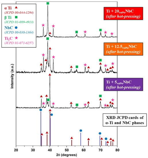
Figure 1.
XRD patterns of the Ti/NbC system.
The calculation of the phase percentage using Rietveld’s method resulted in Table 1 and showed that for the highest addition of NbC (20 vol.%), the obtained composite was predominantly composed of β-Ti (48%) and Ti2C (42%), along with the small amount of α-Ti phase (10%). For the composite obtained with the lowest addition of NbC (5 vol.%), the predominant metallic phase was α-Ti (84%), together with β-Ti (8%) and Ti2C (8%). The intermediate mixture of NbC (Ti + 12.5NbC) resulted in a well-balanced phase composition of α-Ti (39%), β-Ti (29%), and Ti2C (32%) phases. In brief, by tailoring the amounts of Ti and NbC reactants, in-situ composites could be designed in terms of the phase composition of the matrix, from predominantly α-Ti to predominantly β-Ti, combined with the increase in reinforcing phase precipitations.

Table 1.
The phase composition (vol.%) of the hot-pressed samples.
Microstructures analyzed by SEM confirmed the XRD findings. Figure 2 presents the micrographs of each obtained composite after etching with Kroll’s reagent. As indicated by the arrows, Ti + 20NbC (Figure 2a) predominantly exhibited a β phase structure in the matrix surrounding Ti2C particles, whereas Ti + 12.5NbC (Figure 2b) showed the reduced presence of β phase along with the appearance of α + β lamellar microstructure in the matrix. Finally, Ti + 5NbC (Figure 2c) had the lowest content of Ti2C particles, and the matrix composed of α + β lamellar microstructure contained the predominance of the α phase.
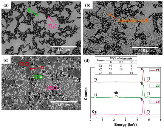
Figure 2.
Microstructural analysis performed by SEM (BSE mode): (a) Ti + 20NbC; (b) Ti + 12.5NbC; (c) Ti + 5NbC; and (d) EDS spectra of the zones represented in (c).
Figure 2d presents the EDS spectra of the composite produced with Ti + 5NbC. Ti and Nb were detected in the lighter region (Z2), whereas Ti and C were detected in the darker region (Z3), and only Ti was detected in the gray region (Z1). These results indicate that the Ti2C phase had a particle-like microstructure embedded in the metallic matrix composed of Ti and Ti-Nb solid solution.
The increase in the amount of the β phase obtained with the higher NbC addition influenced the hardness. Figure 3 provides the results of the Vickers hardness measurements. With the lowest addition of 5 vol.% of NbC, the hardness increased in comparison to unreinforced Ti. Therefore, as unreinforced Ti has an α phase structure, the reinforcement increased the hardness of the composite. However, with a greater NbC addition, the hardness slightly decreased, achieving 387 ± 11 HV30 for Ti + 20NbC due to the combined effect of a softer matrix (β-Ti) with the reinforcing phase [,,,,].
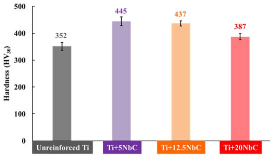
Figure 3.
Vickers hardness values.
3.2. Corrosion Behavior
Figure 4 shows the representative potentiodynamic polarization curves for unreinforced Ti and Ti + NbC composites. In the anodic domain, all of the potentiodynamic polarization curves exhibited a well-defined passivation plateau usually attributed to the presence of a protective oxide film. Notwithstanding, with the higher addition of NbC, the obtained composites revealed a relatively narrower passive region since an increase in the current densities occurred at high potentials, specifically around 1.2 VAg/AgCl for Ti + 12.5NbC and 1.1 VAg/AgCl for Ti + 20NbC. The increase in the current density at those potential values can be attributed to the partial dissolution of the oxide film, which has been reported when a more heterogeneous phase composition is obtained with higher content of the alloying elements []. Kin et al. [] also obtained similar corrosion behavior during potentiodynamic polarization of Ti35Nb alloy samples in Hank’s solution. An increase in the current density at high anodic potential values was linked to the high heterogeneous phase composition of the alloy since that induced more defects in the oxide layer.
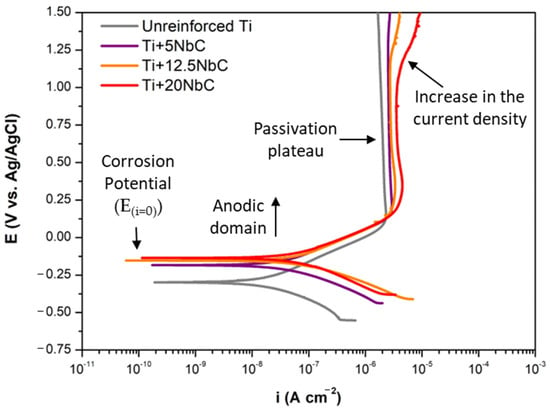
Figure 4.
Potentiodynamic polarization curves for unreinforced Ti and all composites in PBS at 37 °C.
The average corrosion potential (E(i=0)) and passivation current density (ipass) are presented in Table 2 for all groups. Comparing the groups, the lowest corrosion potential was observed for the unreinforced Ti group. As the NbC content increased, the corrosion potential shifted to nobler values. The addition of NbC, according to the structural characterization, promoted the formation of β Ti-Nb solid solution in the metallic matrix. It is well-known that Ti-Nb alloys show more positive corrosion potential than pure Ti since Nb is a nobler metal than Ti [,].

Table 2.
Average values of corrosion potential (E(i=0)) and passivation current density (ipass).
However, increased passivation current densities were observed with composites compared to unreinforced Ti. The passive current density increased when NbC was added, with no significant differences among the composites. This slightly higher corrosion kinetics might be attributed to the presence of the Ti2C phase and eventual modifications of the passive film. Similar results have been reported for unreinforced Ti-Nb alloys [,], where the oxide layers were composed of TiO2 and Nb2O5 and, depending on the formation conditions and thermomechanical history, may result in the formation of a different nature of the oxide film. Furthermore, the galvanic coupling between the matrix and the reinforcement may have occurred and contributed to the impairment of the corrosion behavior, as this has commonly been reported for MMCs [,,,]. In this scenario, the EIS measurements performed at OCP provided more precise insight into the corrosion mechanisms.
Figure 5a is the Nyquist diagram for unreinforced Ti and the composites. Each diagram exhibits a single time constant, which is represented by the single semi-circle on the Nyquist diagram and the single loop on the Bode diagram. Unreinforced Ti shows the largest semi-circle diameter, which means higher corrosion resistance, whereas the diameter decreased with the addition of NbC. EIS measurements also allowed the construction of the Bode diagrams, presented in Figure 5b. Furthermore, the EIS results were fitted based on the equivalent electrical circuit (EEC) defined in Figure 5c, where is the electrolyte resistance, is the oxide film resistance, and is a constant phase element (CPE) considering the non-ideal capacitance of the oxide film.
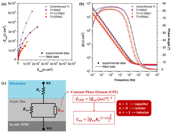
Figure 5.
(a) Nyquist diagram; (b) Bode diagram; (c) EEC and definitions for fitting the EIS data.
Analyzing the Bode diagram, the constant values of |Z| at high frequencies is the typical response of the electrolyte resistance, where the phase angle is close to zero. In the low- and middle-frequency range, the phase angle values approached −90° for all of the conditions (for instance, −85° for unreinforced Ti and −82° for Ti + 20NbC), reflecting the typical capacitive behavior of a compact oxide film. The impedance spectra were fitted to the corresponding EEC using Gamry Echem Analyst software (version 5.61, Gamry Instruments, Philadelphia, PA, USA). As shown in Figure 5c, CPE was used in the fitting to allow the deviation of the ideal behavior of a capacitor, and when the value is close to 1, a non-ideal capacitor may be described by this element. All of the conditions presented values between 0.92 and 0.96; thus, the proposed model adequately describes the behavior of the native oxide film in contact with PBS. The differences in the values might be related to the heterogeneities and roughness of the surface. Furthermore, the quality of the model was evaluated through the goodness of fitting () values, and all groups presented values around . Table 3 shows every parameter of each sample condition obtained after fitting EIS data with the proposed EEC.

Table 3.
Equivalent circuit parameters obtained from EIS data.
To facilitate the interpretation of the results, the values were converted to (capacitance) using the equation presented in Figure 5c, derived from Brugg’s equation []. As seen in Table 3, the lowest value was obtained with unreinforced Ti, and the values increased as the NbC content increased, indicating the lower quality of the oxide film formed. The values of varied conversely but in accordance with the capacitance values, confirming the highest resistance of the oxide film of unreinforced Ti. Indeed, as shown above, the NbC additions promoted the incorporation of Nb into the Ti crystallographic lattice, precipitating the β phase in the matrix. According to the literature, for Ti-Nb alloys without quenching or any similar heat-treated condition, a stable β phase is obtained only with an Nb content higher than 30 wt.% [,,]. Recently, it was reported that the oxide films of Ti–Nb alloys became thinner as the Nb content increased, resulting in the lower corrosion resistance for Ti-40wt.%Nb []. Therefore, for the composites produced in the present work, the decrease in the corrosion resistance may be linked with the lower quality of the oxide film resulting from the higher heterogeneous phase composition of the bulk, promoted both by the dissolution of Nb, which resulted in the precipitation of β-Ti phase in the metallic matrix and by the precipitation of the Ti2C phase.
As known, (capacitance of the oxide film) is defined by , where is the vacuum primitivity ( ≈ 8.9 × 10⁻¹⁴ Fcm−1), εr is a dielectric constant of the oxide film, is the exposure area, and is the thickness of the oxide film []. Therefore, the increase in with higher NbC addition (see Table 3) for the composites may be linked to the reduction in the thickness of the oxide film, along with the variations in values resulting from the different nature of their oxide film, which indicates impairment in its quality.
3.3. Tribocorrosion Behavior
The OCP evolution before, during, and after sliding, together with the corresponding coefficient of friction (COF) recorded during sliding, are in Figure 6, which presents the representative behavior of each composite compared to unreinforced Ti. When sliding started, an abrupt drop in the OCP values was recorded for all samples due to the mechanical damage of the oxide film and the exposure of the worn area to the electrolyte. After sliding, the OCP values increased to approximately the values obtained before sliding due to the recovery of the oxide film on the wear tracks. The exception was Ti + 5NbC, which maintained around 500 s in intermediate values, which were about the values recorded for unreinforced Ti, and only then increased up to the OCP registered before sliding (similar behavior was recorded for the Ti + 5NbC samples, but varying the recovering time between 300 and 500 s). This behavior indicates slower repassivation kinetics.
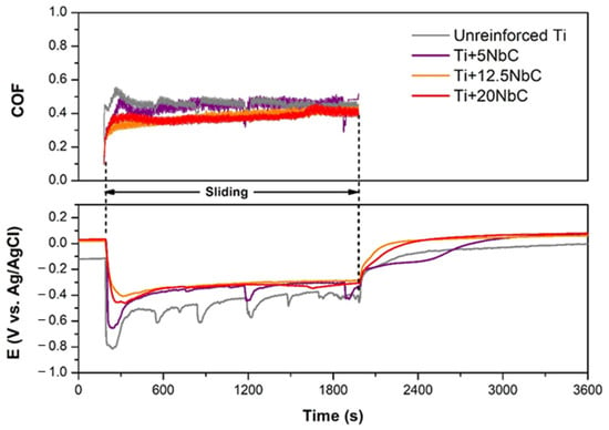
Figure 6.
COF and potential evolutions during tribocorrosion tests performed under OCP.
Regarding the behavior during sliding, Table 4 presents the average values of OCP and COF, which were estimated from three tests for each studied condition. These obtained values indicate a relatively lower thermodynamic tendency to corrode under sliding for all composites, especially Ti + 20NbC and Ti + 12.5NbC, with potential averages higher than −0.4 VAg/AgCl, compared to the unreinforced Ti (potential average around −0.5 VAg/AgCl). Furthermore, unreinforced Ti and Ti + 5NbC presented more profound decreases in potential when sliding started and similar sharp oscillations repeated during sliding. These sharp oscillations may be linked to the formation of patches, which, after reaching a critical thickness, are removed by the counter body. The average COF values tended to decrease as the content of NbC increased. For Ti + 12.5NbC and Ti + 20NbC, COF averages were less than 0.4, and the evolution of COF during sliding showed relatively lower values at the beginning and gradually increased until the end of sliding but never exceeded the values recorded for unreinforced Ti. On the other hand, unreinforced Ti and Ti + 5NbC obtained a higher COF average aside from sharp oscillations linked to their OCP evolution. The repetitive thickening and breaking of the oxide patches may be attributed to unreinforced Ti [,], while for the composites, the higher the amount of reinforcement, the lower the tendency of this behavior to appear due, most probably, to the load-carrying effect of Ti2C particles. As the content of the reinforcement increases, the effect of adhesive wear decreases due to the reduction in the exposed metallic area []. Therefore, the smoother COF evolution was recorded with a higher fraction of reinforcement.

Table 4.
Average values of COF and potential during sliding performed under OCP.
Tribocorrosion tests performed under anodic applied potential enabled further investigation of the interactions between wear and corrosion. Figure 7 presents the anodic current evolution before, during, and after sliding at an applied potential of +0.5 V vs. Ag/AgCl, as well as the corresponding evolution of COF. Before sliding, the current density values were stable due to the presence of the oxide film formed on the surfaces. During sliding, the current evolutions showed different behaviors among the studied conditions. When sliding started, unreinforced Ti presented a sharp increase in current density, whereas the composites, in general, presented a smaller increase in current density, which remained relatively stable around these values. As sliding proceeded, sharp increases in current density were observed for unreinforced Ti, which were also observed for Ti + 5NbC, but less frequent. After unloading the counter-material, the anodic current density of all conditions returned to the values close to the ones recorded before sliding, indicating the repassivation of the worn area. Regarding the evolution of COF, large oscillations went along with the sharp increases in current density values for unreinforced Ti and Ti + 5NbC, whereas COF remained more stable for Ti + 12.5NbC and Ti + 20NbC.
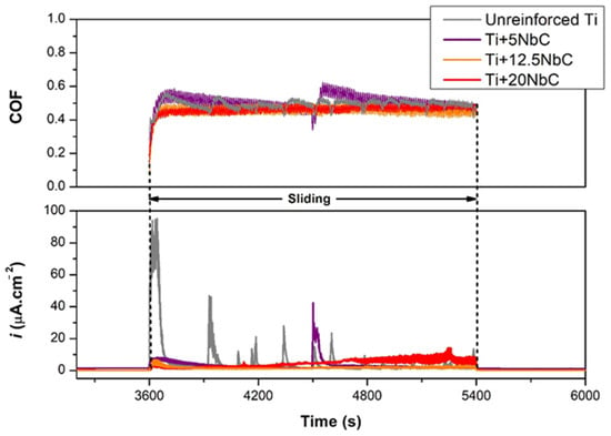
Figure 7.
COF and current density evolutions during tribocorrosion tests performed under anodic applied potential.
Table 5 elucidates that the COF of all of the sample conditions under anodic applied potential was higher than the values obtained under OCP. This increase can be associated with the thickening of the oxide film due to the applied potential on the anodic domain. In this case, the thicker oxide layer may correspond to a relatively rougher surface, and when a counter-material promotes the cyclic damage, it may result in increased formation of the oxidized third-body particles []. Likewise, the Ti + 20NbC condition recorded a progressive increase in current density along with the evolution of the experiment, culminating in high values in the final seconds of the sliding period (around 10 µA cm−2). This behavior may be linked to the worse corrosion resistance among all studied conditions since the EIS and potentiodynamic polarization results demonstrated a decreased quality of the oxide film of the composites as they were produced with a higher addition of NbC. Therefore, the effect of third-body wear must have been accentuated for the Ti + 20NbC samples with the sliding performed under anodic applied potential. On the other hand, the more reinforced the composites are, the lower the influence of adhesive wear, which explains the variation in the COF values among the composites since the COF tended to decrease with a higher addition of NbC. The intermediate content of NbC (Ti + 12.5NbC) did not present the progressive increase in current density values as with Ti + 20NbC, whereas its COF values tended to be lower than those recorded for Ti + 5NbC.

Table 5.
Average values of COF and anodic charge (QA) estimated during sliding performed under +0.5 V vs. Ag/AgCl.
As the applied potential value (+0.5 V vs. Ag/AgCl) corresponds to the passive zone for all testing groups, the material degradation is assumed to have resulted from two mechanisms: mechanical wear (), and wear accelerated corrosion () []. Through this approach, the total volume loss after tribocorrosion () is the sum of both wear components. Individually for each studied condition, the contribution of is proportional to the anodic charge () estimated through the integration of the current curves over sliding time. Although is also influenced by the molecular weight and valance electron number, its value directly reflects the passage of current per area, thus with lower , lower corrosion kinetics under sliding is expected. For the composites and unreinforced Ti, the average values obtained with three samples per condition are presented in Table 5. A significant difference can be seen for the Ti + 12.5NbC condition, which exhibited the lowest value (around 50% of the value obtained by unreinforced Ti).
Representative micrographs obtained by OM and SEM of the worn surfaces after being tested under OCP, are presented in Figure 8. First, as can be observed in Figure 8, the relatively low level of surface damage on the composites after tribocorrosion testing did not allow a valid measurement of the wear volume loss. In addition, there were no macroscopic signals or changes in the color of the counter-body (alumina balls) after testing, and the analyses of its surface on the microscale were discarded. Comparing the OM images, unreinforced Ti (Figure 8a) presented a much larger wear track than the composite samples. Parallel ploughing grooves and abrasion scratches can be observed on the worn surface of unreinforced Ti, together with a discontinuous tribolayer (oxidized patches), which are evidenced in BSE mode (Figure 8b). This surface morphology has been typically reported in the literature for Ti and Ti alloys [,]. Figure 8c presents the EDS spectrum 1 (Z1) and 2 (Z2) obtained in the unreinforced Ti sample. As it can be seen, Z2 refers to the bulk composition (only Ti), whereas Z1 (oxidized patches) shows signs of K, O, P, and Na, indicating oxidation with the incorporation of elements from the PBS electrolyte. This tribolayer may offer protection against wear and corrosion up to a certain thickness, but it can then be removed by the counter-material and thus accelerate the degradation, as was discussed above.
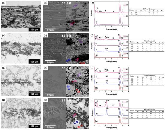
Figure 8.
OM and SEM images together with EDS spectra of worn surfaces after tribocorrosion performed under OCP for: unreinforced Ti (a–c), Ti + 5NbC (d–f), Ti + 12.5NbC (g–i), and Ti + 20NbC (j–l).
Regarding the composites, OM images depict the thinnest wear track on the Ti + 12.5NbC sample (Figure 8g), which can be attributed to the load-carrying effect given by the higher content of the reinforcing phase. However, higher amounts of reinforcing phase might lead to a deleterious effect, as indicated by the larger wear track displayed by the Ti + 20NbC sample (Figure 8j). This behavior should be further investigated in future works but may be attributed to the removal of reinforcing particles, resulting in more damage to the metallic matrix. A discontinuous tribolayer formation was detected by EDS analysis in each composite (Z1 EDS spectra for each sample).
Figure 9 presents the representative micrographs (OM and SEM) and EDS spectra of the worn surfaces when sliding occurred under anodic applied potential. From the OM images, it can be observed that unreinforced Ti and Ti + 5NbC showed a thinner wear track (Figure 9a,d) when compared to the results obtained under the OCP conditions. On the other hand, Ti + 20NbC showed the opposite trend with a relatively larger wear track (Figure 9j).
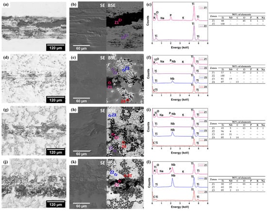
Figure 9.
OM and SEM images together with EDS spectra of worn surfaces after tribocorrosion performed under anodic applied potential for: unreinforced Ti (a–c), Ti + 5NbC (d–f), Ti + 12.5NbC (g–i), and Ti + 20NbC (j–l).
As was discussed before, the addition of NbC resulted in a decrease in the corrosion resistance of the materials (increase in the passivation current density and a decrease in the oxide film resistance), suggesting a less protective passive oxide film formed on the composites. At the same time, as the addition of NbC increased, the percentage of the Ti2C phase also increased, which can lead to an effective protective load-carrying effect during tribocorrosion, if the Ti2C does not become organized in dense clusters, facilitating the removal of particles during sliding. Therefore, as is suggested in Figure 9k,l, the presence of the tribolayer aside from the signals of the removed Ti2C particles on the wear track of Ti + 20NbC sample can be observed.
3.4. Limitations of the Present Study
The first insights into the tribocorrosion behavior of novel in-situ TMCs were investigated in the present study. Regarding the combined factors which can play an important role in the tribocorrosion resistance of composites, new directions for further research were opened due to the obtained results, and the limitations of this paper should be highlighted.
Firstly, as shown, the addition of NbC results in the in-situ formation of new phases as well as modification of the matrix structure and composition. Consequently, the formation of new phases may lead to complex electrochemical interactions (namely galvanic coupling) at different scales, which were not within the aim of this paper.
Furthermore, the chemical composition, and physical properties of the passive oxide film, which are also influenced by the base composition of the mixture, the processing conditions, and the environmental aspects, were not investigated in this paper. Therefore, further experiments should be conducted regarding these issues.
4. Conclusions
The present study evidenced the following:
- In-situ composites can be produced by Ti + NbC starting materials. When applying hot pressing at 1100 °C for 120 min, the Ti powder reacted in the solid-state with NbC powder, resulting in the dissolution of Nb into the metal matrix and precipitating Ti2C as the hard-ceramic reinforcement. The higher amount of NbC applied led to a higher amount of reinforcement and a higher amount of the Ti-Nb β phase in the matrix. For 20 vol.% of NbC, the final composite had a predominant β matrix reinforced with 42% of Ti2C.
- The corrosion resistance of the composites was mainly affected by the different quality of the oxide film. With the higher addition of NbC, the protection given by the oxide film was reduced. On the other hand, as in-situ processing allows the production of composites with low porosity and well-established matrix/reinforcement interfaces, no effect was detected by EIS and potentiodynamic polarization tests of localized corrosion or galvanic coupling.
- Improved tribocorrosion behaviors were registered for the composites. The best tribocorrosion behavior was obtained with α-β matrix and high reinforced composite (Ti + 12.5NbC), which exhibited the lowest corrosion tendency and kinetics under sliding among all studied conditions together with a polished wear track. Furthermore, the low corrosion tendency under sliding achieved with the predominant β matrix composite (Ti + 20NbC) demonstrates that wear is not entirely hardness dependent.
Author Contributions
Conceptualization, V.R.M.G., I.Ç., A.C.A., F.T. and L.A.R.; methodology, V.R.M.G., I.Ç., A.C.A., F.T. and L.A.R.; validation, V.R.M.G., I.Ç., A.C.A., F.T. and L.A.R.; investigation, V.R.M.G., I.Ç., A.C.A., F.T. and L.A.R.; writing—original draft preparation, V.R.M.G.; writing—review and editing, I.Ç., A.C.A., F.T. and L.A.R.; supervision, F.T. and L.A.R. All authors have read and agreed to the published version of the manuscript.
Funding
This work was supported by São Paulo Research Foundation (FAPESP), grants #2017/24300-4, #2018/00746-6 and #2019/07953-0. Also, this work was partially supported by Portuguese Foundation for Science and Technology (FCT), Portugal, under UIDB/04436/2020 project.
Data Availability Statement
Not applicable.
Acknowledgments
The authors would like to acknowledge Ana Maria Pires Pinto for the support and the provision of several equipment and goods used during the evolution of the work. Moreover, the authors would like to acknowledge Diego Rafael Nespeque Correa for the aid during the study of phase composition applied in the present paper.
Conflicts of Interest
The authors declare no conflict of interest.
References
- Chen, Q.; Thouas, G.A. Metallic implant biomaterials. Mater. Sci. Eng. R Rep. 2015, 87, 1–57. [Google Scholar] [CrossRef]
- Niinomi, M. Design and development of metallic biomaterials with biological and mechanical biocompatibility. J. Biomed. Mater. Res. Part A 2019, 107, 944–954. [Google Scholar] [CrossRef] [PubMed]
- Lütjering, G.; Williams, J.C. Fundamental Aspects. In Titanium, 2nd ed.; Springer: Berlin/Heidelberg, Germany, 2007; pp. 15–52. [Google Scholar]
- Kolli, R.P.; Devaraj, A. A Review of Metastable Beta Titanium Alloys. Metals 2018, 8, 506. [Google Scholar] [CrossRef] [Green Version]
- Chen, L.-Y.; Cui, Y.-W.; Zhang, L.-C. Recent Development in Beta Titanium Alloys for Biomedical Applications. Metals 2020, 10, 1139. [Google Scholar] [CrossRef]
- Bahl, S.; Suwas, S.; Chatterjee, K. Comprehensive review on alloy design, processing, and performance of β Titanium alloys as biomedical materials. Int. Mater. Rev. 2020, 66, 114–139. [Google Scholar] [CrossRef]
- Sidhu, S.S.; Singh, H.; Gepreel, M.A.-H. A review on alloy design, biological response, and strengthening of β-titanium alloys as biomaterials. Mater. Sci. Eng. C 2020, 121, 111661. [Google Scholar] [CrossRef]
- Yamako, G.; Janssen, D.; Hanada, S.; Anijs, T.; Ochiai, K.; Totoribe, K.; Chosa, E.; Verdonschot, N. Improving stress shielding following total hip arthroplasty by using a femoral stem made of β type Ti-33.6Nb-4Sn with a Young’s modulus gradation. J. Biomech. 2017, 63, 135–143. [Google Scholar] [CrossRef]
- Kunčická, L.; Kocich, R.; Lowe, T.C. Advances in metals and alloys for joint replacement. Prog. Mater. Sci. 2017, 88, 232–280. [Google Scholar] [CrossRef]
- Gilbert, J.L.; Zhu, D. A metallic biomaterial tribocorrosion model linking fretting mechanics, currents, and potentials: Model development and experimental comparison. J. Biomed. Mater. Res. Part B Appl. Biomater. 2020, 108, 3174–3189. [Google Scholar] [CrossRef]
- Hoeppner, D.; Chandrasekaran, V. Fretting in orthopaedic implants: A review. Wear 1994, 173, 189–197. [Google Scholar] [CrossRef]
- Bijukumar, D.R.; Segu, A.; de Souza, J.C.M.; Li, X.; Barba, M.; Mercuri, L.G.; Jacobs, J.J.; Mathew, M.T. Systemic and local toxicity of metal debris released from hip prostheses: A review of experimental approaches. Nanomed. Nanotechnol. Biol. Med. 2018, 14, 951–963. [Google Scholar] [CrossRef] [PubMed]
- Revell, P.A. The combined role of wear particles, macrophages and lymphocytes in the loosening of total joint prostheses. J. R. Soc. Interface 2008, 5, 1263–1278. [Google Scholar] [CrossRef] [PubMed] [Green Version]
- Çaha, I.; Alves, A.C.; Rocha, L.A.; Toptan, F. A Review on Bio-functionalization of β-Ti Alloys. J. Bio- Tribo-Corros. 2020, 6, 135. [Google Scholar] [CrossRef]
- Wood, R. Tribo-corrosion of coatings: A review. J. Phys. D Appl. Phys. 2007, 40, 5502–5521. [Google Scholar] [CrossRef]
- Attar, H.; Ehtemam-Haghighi, S.; Soro, N.; Kent, D.; Dargusch, M.S. Additive manufacturing of low-cost porous titanium-based composites for biomedical applications: Advantages, challenges and opinion for future development. J. Alloys Compd. 2020, 827, 154263. [Google Scholar] [CrossRef]
- Hayat, M.D.; Singh, H.; He, Z.; Cao, P. Titanium metal matrix composites: An overview. Compos. Part A Appl. Sci. Manuf. 2019, 121, 418–438. [Google Scholar] [CrossRef]
- Jiao, Y.; Huang, L.; Geng, L. Progress on discontinuously reinforced titanium matrix composites. J. Alloys Compd. 2018, 767, 1196–1215. [Google Scholar] [CrossRef]
- Çaha, I.; Alves, A.C.; Chirico, C.; Pinto, A.M.; Tsipas, S.; Gordo, E.; Toptan, F. Improved tribocorrosion behavior on bio-functionalized β-type titanium alloy by the pillar effect given by TiN reinforcements. Surf. Coat. Technol. 2021, 415, 127122. [Google Scholar] [CrossRef]
- Feest, E. Interfacial phenomena in metal-matrix composites. Composites 1994, 25, 75–86. [Google Scholar] [CrossRef]
- Kaur, M.; Singh, K. Review on titanium and titanium based alloys as biomaterials for orthopaedic applications. Mater. Sci. Eng. C 2019, 102, 844–862. [Google Scholar] [CrossRef]
- Hihara, L.H.; Latanision, R.M. Corrosion of metal matrix composites. Int. Mater. Rev. 1994, 39, 245–264. [Google Scholar] [CrossRef]
- Bobić, B.; Mitrovic, S.; Babic, M.; Bobić, I. Corrosion of aluminium and zinc-aluminium alloys based metal-matrix composites. Tribol. Ind. 2009, 31, 44–53. [Google Scholar]
- Toptan, F.; Rego, A.; Alves, A.C.; Guedes, A. Corrosion and tribocorrosion behavior of Ti–B4C composite intended for orthopaedic implants. J. Mech. Behav. Biomed. Mater. 2016, 61, 152–163. [Google Scholar] [CrossRef] [PubMed]
- Dikici, B.; Bedir, F.; Gavgali, M. The effect of high TiC particle content on the tensile cracking and corrosion behavior of Al–5Cu matrix composites. J. Compos. Mater. 2019, 54, 1681–1690. [Google Scholar] [CrossRef]
- Sannino, A.; Rack, H. Dry sliding wear of discontinuously reinforced aluminum composites: Review and discussion. Wear 1995, 189, 1–19. [Google Scholar] [CrossRef]
- Aikin, R.M. The mechanical properties of in-situ composites. JOM 1997, 49, 35–39. [Google Scholar] [CrossRef]
- Tjong, S.C. Microstructural and mechanical characteristics of in situ metal matrix composites. Mater. Sci. Eng. R Rep. 2000, 29, 49–113. [Google Scholar] [CrossRef]
- Silva, J.; Alves, A.; Pinto, A.; Toptan, F. Corrosion and tribocorrosion behavior of Ti–TiB–TiNx in-situ hybrid composite synthesized by reactive hot pressing. J. Mech. Behav. Biomed. Mater. 2017, 74, 195–203. [Google Scholar] [CrossRef]
- Trung, T.B.; Zuhailawati, H.; Ahmad, Z.A.; Ishihara, K.N. Grain growth, phase evolution and properties of NbC carbide-doped WC-10AISI304 hardmetals produced by pseudo hot isostatic pressing. J. Alloys Compd. 2012, 552, 20–25. [Google Scholar] [CrossRef]
- Zhou, W.; Xiong, J.; Wan, W.; Guo, Z.; Lin, Z.; Huang, S.; Tang, L.; Zhong, H. The effect of NbC on mechanical properties and fracture behavior of WC–10Co cemented carbides. Int. J. Refract. Met. Hard Mater. 2015, 50, 72–78. [Google Scholar] [CrossRef]
- Huang, S.; Nie, H.; Guo, X.; Vleugels, J.; Huang, J.; Mohrbacher, H.; Rajendhran, N.; Sukumaran, J.; De Baets, P.; Cannizza, E.; et al. Microstructural investigation and machining performance of NbC-Ti(C0.5N0.5) matrix cermets. Int. J. Refract. Met. Hard Mater. 2019, 84, 105038. [Google Scholar] [CrossRef]
- Chang, S.-H.; Hung, L.-Y.; Yang, T.-H. The effects of adding micro-scaled niobium carbide on the microstructure, mechanical strength and polarization resistance of the Ti–8Mo–4Co-xNbC composites. Mater. Chem. Phys. 2019, 235, 121743. [Google Scholar] [CrossRef]
- Çaha, I.; Alves, A.C.; Kuroda, P.; Grandini, C.R.; Pinto, A.; Rocha, L.; Toptan, F. Degradation behavior of Ti-Nb alloys: Corrosion behavior through 21 days of immersion and tribocorrosion behavior against alumina. Corros. Sci. 2020, 167, 108488. [Google Scholar] [CrossRef]
- Thoemmes, A.; Bataev, I.A.; Belousova, N.S.; Lazurenko, D.V. Microstructure and mechanical properties of binary Ti-Nb alloys for application in medicine. In Proceedings of the 2016 11th International Forum on Strategic Technology (IFOST), Novosibirsk, Russia, 1–3 June 2016; pp. 26–29. [Google Scholar] [CrossRef]
- Lee, C.M.; Ju, C.P.; Lin, J.H.C. Structure-property relationship of cast Ti-Nb alloys. J. Oral Rehabil. 2002, 29, 314–322. [Google Scholar] [CrossRef] [PubMed]
- Yahaya, M.; Sahidin Salehudin, S.; Sulaiman, M.; Shah, N.H.N.E.A.; Ismail, M.H. Microstructures and Mechanical Properties of Ti-Nb Alloy at Different Composition of Nb Produced via Powder Metallurgy Route. Mater. Sci. Forum 2016, 863, 14–18. [Google Scholar] [CrossRef]
- Bai, Y.; Deng, Y.; Zheng, Y.; Li, Y.; Zhang, R.; Lv, Y.; Zhao, Q.; Wei, S. Characterization, corrosion behavior, cellular response and in vivo bone tissue compatibility of titanium–niobium alloy with low Young’s modulus. Mater. Sci. Eng. C 2015, 59, 565–576. [Google Scholar] [CrossRef]
- Geetha, M.; Mudali, U.K.; Gogia, A.; Asokamani, R.; Raj, B. Influence of microstructure and alloying elements on corrosion behavior of Ti–13Nb–13Zr alloy. Corros. Sci. 2004, 46, 877–892. [Google Scholar] [CrossRef]
- Qin, P.; Chen, L.; Zhao, C.; Liu, Y.; Cao, C.; Sun, H.; Zhang, L. Corrosion behavior and mechanism of selective laser melted Ti35Nb alloy produced using pre-alloyed and mixed powder in Hank’s solution. Corros. Sci. 2021, 189, 109609. [Google Scholar] [CrossRef]
- Orazem, M.E.; Tribollet, B. Electrochemical Impedance Spectroscopy, 2nd ed.; Jonh Wiley & Sons: Hoboken, NJ, USA, 2017. [Google Scholar]
- Bharat, N.; Bose, P. An overview on the effect of reinforcement and wear behaviour of metal matrix composites. Mater. Today Proc. 2021, 46, 707–713. [Google Scholar] [CrossRef]
- Mischler, S. Triboelectrochemical techniques and interpretation methods in tribocorrosion: A comparative evaluation. Tribol. Int. 2008, 41, 573–583. [Google Scholar] [CrossRef]
- Çaha, I.; Alves, A.; Chirico, C.; Pinto, A.; Tsipas, S.; Gordo, E.; Toptan, F. Corrosion and Tribocorrosion Behavior of Ti-40Nb and Ti-25Nb-5Fe Alloys Processed by Powder Metallurgy. Met. Mater. Trans. A 2020, 51, 3256–3267. [Google Scholar] [CrossRef]
Publisher’s Note: MDPI stays neutral with regard to jurisdictional claims in published maps and institutional affiliations. |
© 2022 by the authors. Licensee MDPI, Basel, Switzerland. This article is an open access article distributed under the terms and conditions of the Creative Commons Attribution (CC BY) license (https://creativecommons.org/licenses/by/4.0/).