Article

Optimization of Vacuum Brazing Process Parameters in Ti-6Al-4V Alloy

1
Department of Mechanical Engineering, National Central University, Taoyuan 320317, Taiwan
2
Institute of Nuclear Energy Research, Taoyuan 325207, Taiwan
*
Author to whom correspondence should be addressed.
Metals 2022, 12(6), 974; https://doi.org/10.3390/met12060974
Submission received: 4 May 2022 / Revised: 26 May 2022 / Accepted: 31 May 2022 / Published: 6 June 2022

Abstract

:
In this study, the optimal parameters of the vacuum brazing titanium alloy Ti-6Al-4V with TiCuNi filler (30 μm-thick metal foil) were investigated by the Taguchi method. The microstructures, microhardness, and fractographs of the titanium brazed joints produced by these optimal parameters were also analyzed. The results of this study demonstrate that for the best tensile strength, the optimal combination of process parameters is: 890 °C soaking temperature, 60 min soaking time, 975 °C brazing temperature, and 45 min brazing time. The tensile strength obtained by welding with the optimal parameters was found to be 1265 MPa. A small error of 0.24% between experimental and predicted values confirmed the validity of the combined optimized parameters. Finally, from the means of variance analysis (ANOVA), out of the four factors, the highest contribution to the optimal parameters was found to be the brazing time, accounting for 47.3%. The base material of vacuum brazing (VB) weldment is mainly composed of white granular α titanium, slender β titanium, and layered structures that are interlaced by α and β. The weld bead, composed of Ti-15Cu-15Ni, contains many slender needle-shaped Widmanstätten structures. This structure is associated with higher strength and lower ductility. The weld bead hardness of the vacuum brazed parts is higher than that of laser beam weldment and gas tungsten arc weldment. This study demonstrates the feasibility of the Taguchi method for obtaining the optimal process parameters of titanium vacuum brazed joints.

1. Introduction

Titanium alloys exhibit an excellent combination of high specific strength, corrosion resistance, and high-temperature properties. As a result, they are employed in a wide range of applications, such as military, aerospace, automobile, offshore equipment, sports equipment, and biomedical implants. However, in engineering applications, titanium alloys often need to be welded. Many joining methods such as gas tungsten arc welding (GTAW), electron beam welding (EBW), laser beam welding (LBW), diffusion bonding, and brazing can be used for the joining of titanium alloys [1].
Vacuum brazing (VB) is carried out in a vacuum environment and can thus effectively reduce any oxidation problems to retain a metallic luster after welding. Furthermore, for vacuum brazing, there are no flux requirements, or issues with post-weld cleaning or corrosion, meaning that it has excellent bonding quality. Due to being uniformly heated in a vacuum furnace, only minor deformation and residual stress of the workpiece occur. Vacuum brazing has also been applied to create honeycomb sandwich structures of titanium alloy. Such structural parts have a high specific strength and corrosion and heat resistance, making them suitable for use in aircraft parts, such as the fuselage, wing, and engine nozzle [2].
The quality of vacuum brazed parts is dependent upon the technique used and the following factors; Ti-6Al-4V vacuum brazing is mainly divided into two types: similar brazing [3,4,5,6,7,8] and dissimilar brazing [9,10,11,12,13,14,15,16,17,18]. It is apparent that many process parameters such as temperature [4,5,6,10], time [19], and cooling rate [3] affect vacuum brazing. Moreover, the selection of filler foil greatly influences the mechanical properties of the alloy after welding [5,20,21]. As can be seen from the related articles mentioned above, there are many process parameters that affect vacuum brazing, and the selection of parameters has a great influence on the mechanical properties after welding.
In this study, the Taguchi method was used to optimize the process parameters for the tensile strength of Ti-6Al-4V. The contribution of each process parameter toward tensile strength was then studied via variance analysis. A validation experiment was performed to analyze the applicability of this method with a Ti-6Al-4V vacuum furnace, which can control temperature and time precisely. There are quite a number of references for the study of vacuum brazing technology, which are highly relevant to this study.
Finally, the metallographic and mechanical properties of VB weldment, under the optimum process conditions, were also discussed.

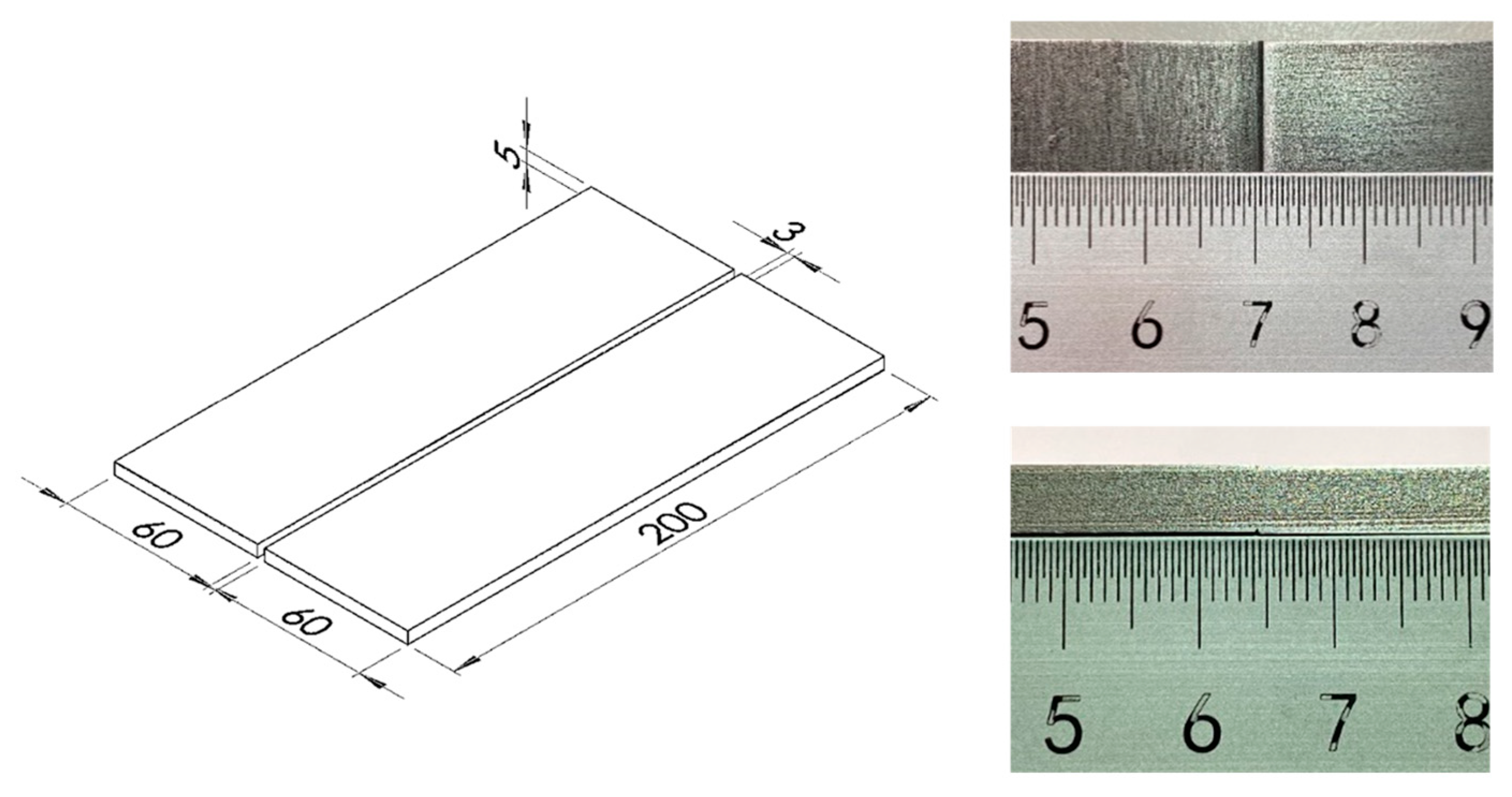
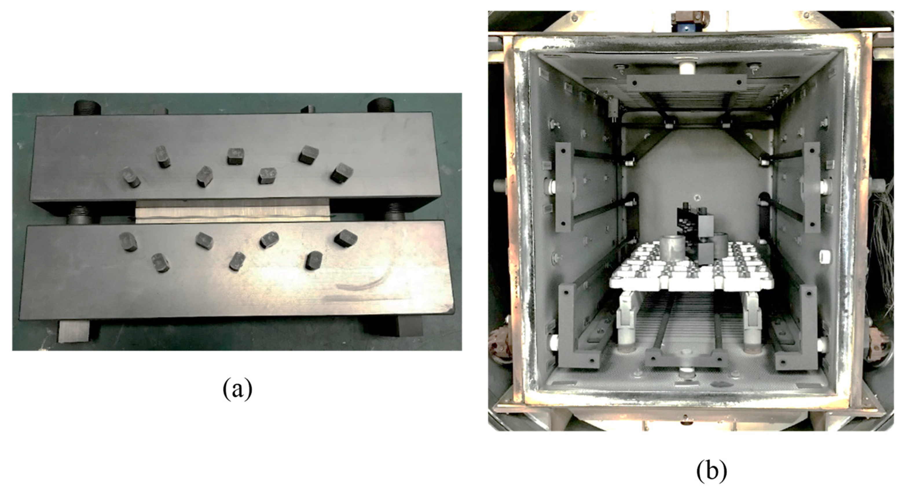
2. Materials and Methods

For this experiment, the base material used was Ti-6Al-4V, with TiCuNi in ribbon shape used for the filler material. The constituent elements for this are shown in Table 1. The experimental procedure was as follows: The base metal plate (as shown in Figure 1) was placed into a graphite jig, with the filler metal placed in between the two base materials so that the specimen was placed in a butt welding arrangement (as shown in Figure 2a). The jig was then locked and placed in the center of the upright vacuum furnace (as shown in Figure 2b). Due to graphite having rapid, uniform heat conduction and a small thermal expansion coefficient, a graphite jig was used instead of the common metal jig for this experiment. Due to the difference in the thermal expansion coefficient between the graphite fixture and the titanium plate, the titanium plate can bear a compressive stress of about 40.8 MPa during brazing. As a result, when vacuum brazing with a graphite jig, we were able to overcome the small contact area, allowing for the successful completion of the thin plate joint.
In order to optimize the parameters used in this experiment, the Taguchi method was employed. In this method, the quality characteristics of each group of experiments were first converted into their corresponding signal-to-noise (S/N) ratios. An orthogonal table was used to obtain the individual effects (i.e., the average S/N ratio) of each factor at different levels via main effect analysis. The results were then summarized using response tables and charts, where a larger S/N ratio represented a better-quality system. Main effect analysis could then be used to determine the optimal combination for each factor level. The S/N ratio was only an indicator of the quality of each control condition. It could not be used to judge the difference in quality characteristics of each control factor, nor could it be used to determine the influence of each control factor. Therefore, variance analysis was used to understand the contribution of each control factor and how each could be altered to obtain the maximum benefit throughout the vacuum brazing process.
In terms of process parameters, 30 μm-thick foil fillers with a composition of Ti-15Cu-15Ni were used (with suggested standard operating conditions of 980 °C brazing temperature, holding for 15 min, 910 °C solid point temperature, and 960 °C liquid point temperature).
Regarding the vacuum furnace performance (as shown in Table 2), for the base material properties and the working solder temperature, the following process parameters and levels were selected: A temperature and timing for the first stage of 500 °C and 30 min was chosen, only to ensure that the temperature of the whole system reached uniformity; they were therefore not taken into consideration by the control factor. For the second stage, the soaking temperatures and times were 850, 870, and 890 °C, and 30, 45, and 60 min, respectively, with brazing temperatures and times of 975, 990, and 1005 °C and 15, 30, and 45 min, respectively. Figure 3 shows the parameters used for the vacuum brazing process. To make the furnace temperature uniform, the temperature was held at 500 °C for 30 min, with the heating then continuing after. The four control factors (A, B, C, and D) and the three levels (1, 2, and 3) were recorded in Table 3. Vacuum brazing was performed according to the L9 (34) orthogonal table under the Taguchi method.
After mounting, grinding, and polishing, the morphology specimens were corroded by ASTM Kroll’s Reagent for 15–25 s. They were then cleaned and dried with water and alcohol. Observations were made at different positions, such as the weld bead, heat affected zone, and the base material.
The tensile test was then carried out using the MTS 810 testing machine (MTS Systems Corporation, Minneapolis, MN, USA), with reference to ASTM E8 specifications: an initial tensile rate of 0.2 mm/s and a subsequent tensile rate of 2.0 mm/s. The test piece adopted the butt welding method, and the upper and lower surfaces were milled to a thickness of 3.5 mm. In the preliminary test, the fracture positions of the test pieces were all located within the base material. To understand the tensile strength of the weld bead, grooves were made on both sides of the test piece weld bead, with a depth of 1.0 mm, an angle of 60°, a radius of 0.2 mm (equal to the root of the notch), and a stress concentration factor of 3.1, as shown in Figure 4 [22].
The microhardness testing machine used in this study was a FM-700E. Prior to using this, the test material was cut into 10 mm × 6 mm × 5 mm pieces using the grinding wheel cutting machine. They were then mounted, ground, and polished. The microhardness test was carried out with a load of 500 gf for 15 s, with the direction of measurement taken along the horizontal axis passing through the base metal and weld bead. To reduce the effect of strain hardening, a distance of at least five times the crater size was used between each measurement.
After the tensile test, the samples were cut to an appropriate size with a cutting machine, cleaned in alcohol with an ultrasonic cleaning machine, and then observed and analyzed using a macroscope and scanning electron microscopy (SEM).

3. Results and Discussion

In this study, a TiCuNi filler was used for Ti-6Al-4V vacuum brazing. The Taguchi method was used to optimize the brazing parameters, with the percentage of influence of each control factor over tensile property calculated via variance analysis. A parameter verification test was used to observe the experiment. Finally, microhardness, metallographic structure, and fracture section were observed.

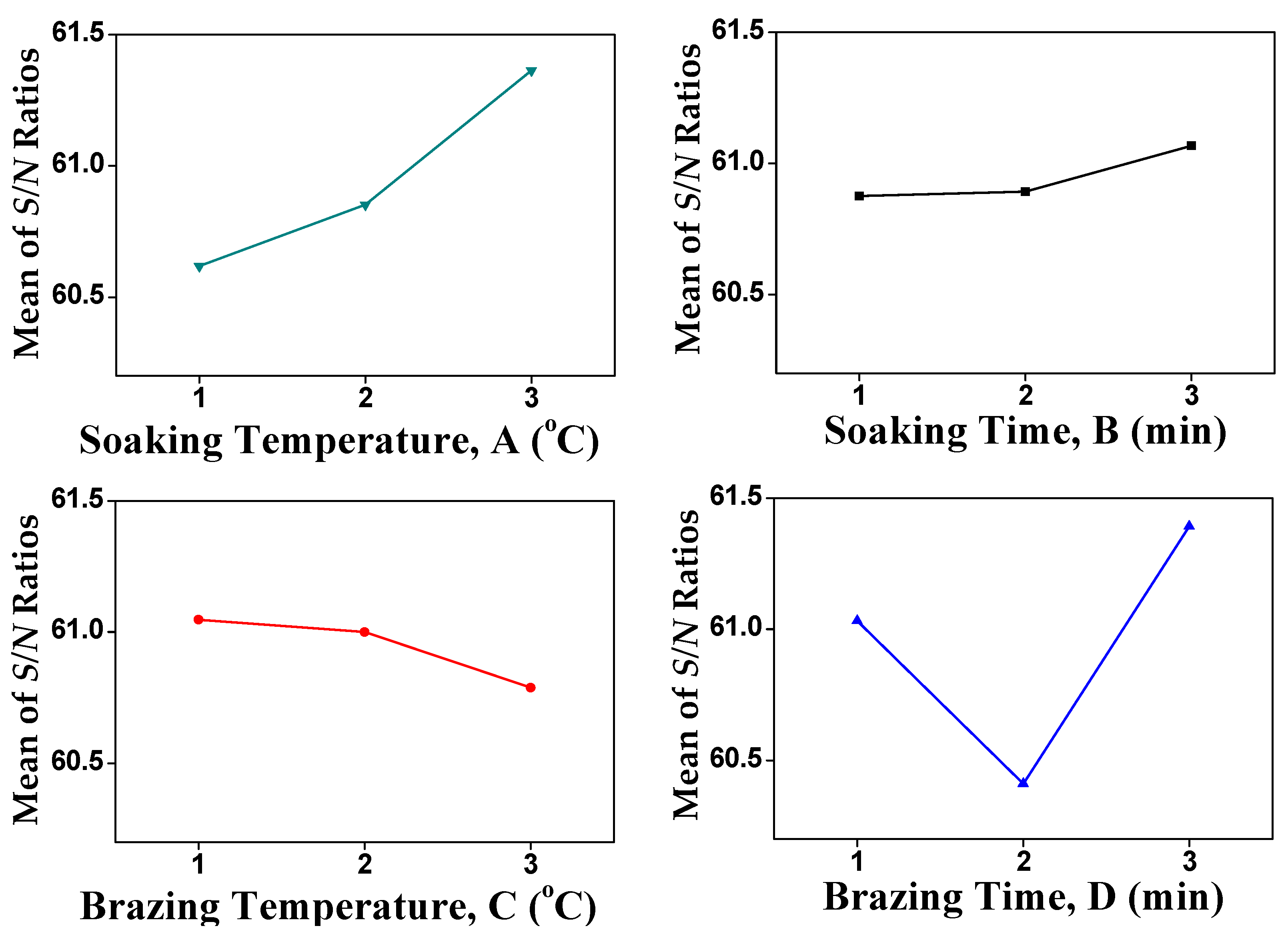
3.1. Process Parameter Optimization

The quality characteristics of general products can be divided into three categories: larger the better (LTB), smaller the better (STB), and nominal the best (NTB) [23,24,25]. In this study, the tensile strength was used as a quality parameter, where higher observed values were considered to be better. Hence, the quality characteristics for this parameter belonged to the LTB category, and its S/N ratio could be expressed as follows:
S N = 10 log 10 1 n i = 1 n 1 y i 2  
where yi is the i-th experimental data for each experimental combination.
The signal-to-noise ratios of each parameter, obtained using Equation (1), are shown in Table 4. Table 5 represents the response, which was obtained by a new classification and sorting of the signal noise density. This information is also presented in a graphical format, as a response graph, in Figure 5. According to the quality requirements of this experiment, the maximum value in the response table was omitted, and the optimal parameter found was A3B3C1D3.

3.2. Variance Analysis (ANOVA)

Variance analysis can be used to perform an F-test on data via statistical methods. The F-value obtained from this test can then be used to determine the degree of dispersion present between datasets. In this experiment, a three-way ANOVA test was used, where a larger F-value signified a higher degree of dispersion, thus indicating that this criterion had a greater influence on experimental results. The sum of squares of treatment (SST) and the sum of squares of error (SSE) were obtained using Equations (2) and (3), respectively. Because this study used three levels in each factor, both the degree of freedom (DF) and the number of slices used for each parameter were equal to three. Substituting the obtained values into Equations (4) and (5) then allowed for the mean square of treatment (MST) and the mean square of error (MSE) to be calculated, respectively. The F-value for each factor was then obtained using Equation (6). Finally, Equation (7) was used to calculate the degree of contribution of each factor.
According to the ANOVA analysis in Table 6, the degrees of contribution of the four factors were: soaking temperature (A) 27.7%, soaking time (B) 47.3%, brazing temperature (C) 3.6%, and brazing time (D) 21.4%, whereas compared with the aluminum alloy [26], were: soaking temperature (A) 33.5%, soaking time (B) 44.5%, brazing temperature (C) 11.72%, and brazing time (D) 10.24%. It can be concluded that the contributions of soaking temperature and time have higher significance as vacuum brazing parameters.
S S T = i = 1 a j = 1 n y ¯ i . y ¯ .. 2
y ¯ .. , total mean of samples, y ¯ i . , average within sample groups
S S E = i = 1 a j = 1 n y i j y ¯ i . 2
y i j is a single piece
M S T = S S T a 1
a, number of factor
M S E = S S E a n 1  
n, number of specimen
F = M S T M S E
P i = S S F S u m   o f   S S F
Contribution, Pi.

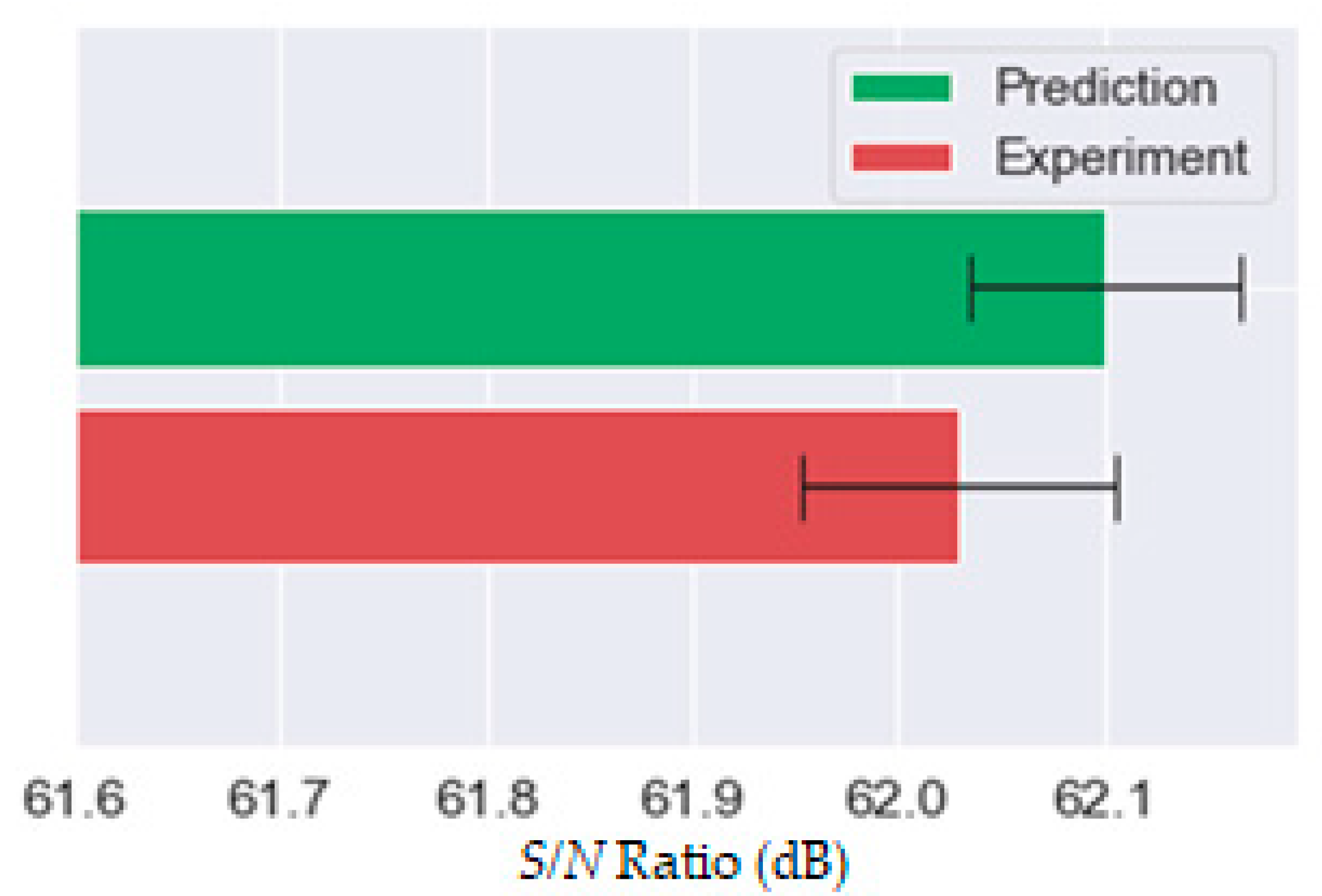
3.3. Confirmation Test

In order to confirm that the combination of process parameters, optimized by the Taguchi method, could meet the expected values, it was necessary to use the optimized parameters A3, B3, C1, and D3 for vacuum brazing. It was also necessary to make associated test pieces and confirm their tensile strength by performing a tensile test. The average tensile strength was found to be 1265 MPa, with the fracture located in the weld bead. Despite this being considerably better than GTAW, the fracture location differs from that typically found in LBW and EBW and therefore cannot be compared.
The optimized predictive value of tensile strength was obtained from Equation (8). After first substituting the average noise ratio of each signal of the optimization parameter into Equation (8), the optimal S/N ratio, S/Nopt, was found to be 62.02 dB. Substituting this value into Equation (9) then yielded an optimal tensile strength, Topt, of 1262 MPa.
S N o p t = T N + A 3 ¯ T N + B 3 ¯ T N + C 1 ¯ T N + D 3 ¯ T N
T o p t = 1 10 S N o p t 10
As shown in Table 7, the error between the average tensile strength of 1265 MPa and the predicted value of 1262 MPa was 3 MPa, which is equal to a difference of only 0.24%. The 95% confidence interval between the predicted and experimental values of tensile strength is shown in Figure 6. From this, it can be seen that the values overlap, demonstrating the validity of this optimized process parameter combination. Subsequent fatigue specimens would therefore be welded using this parameter combination.

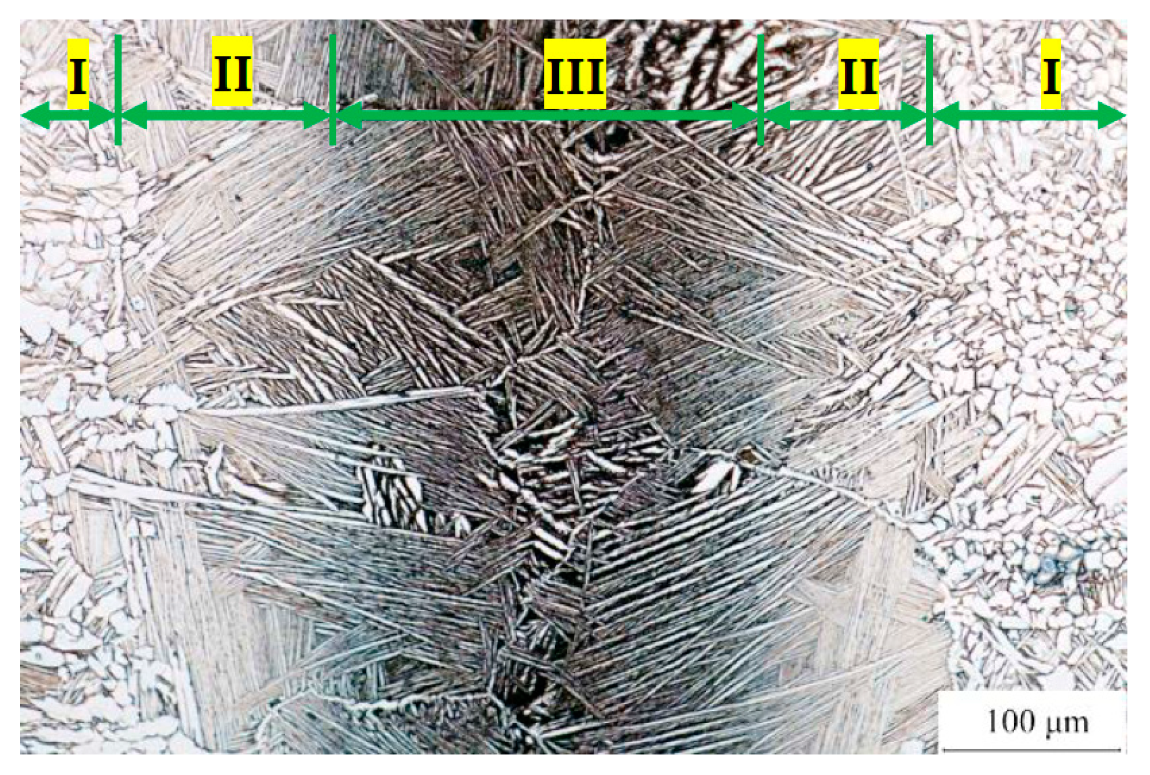
3.4. Microstructures

Observations of the metallographic structure can be used as a basis for discussing the trend of mechanical properties which occur during welding. Contrary to conventional welding, the base and filler metal are put into the furnace together for heating during the vacuum brazing manufacturing process. Once the brazing temperature has been reached, only the solder melts. Because the base metal does not melt throughout the process, a clear interface will be visible between the weld bead and the base metal.
The brazing temperature and time play a crucial role in the brazing process of the titanium alloy [27]. To a certain extent, the brazing temperature is dependent upon the melting temperature of the filler metal used, while the brazing time alters according to the brazing temperature. Once the brazing temperature has exceeded the β phase transition temperature of TC4 at 990 °C, the microstructure of the substrate transforms into acicular (α + β) – Ti and becomes larger and coarser. This leads to a deterioration of the base material properties [28,29].
Although the base metal is not molten, the microstructure of the base metal transforms after the holding and cooling stages on account of the brazing temperature reaching the solid solution temperature of the base metal. Figure 7 shows the metallographic diagram of the base material after the vacuum brazing of Ti-6Al-4V. From this, it can be seen that the base material is mainly composed of white granular α titanium, slender β titanium, and layered structures interlaced by α and β.
Regarding the weld bead metallography of Ti-6Al-4V after vacuum brazing, the regions contain base metal (region I), diffusion layer (region II), and weld bead (region III), as shown in Figure 8. Upon close inspection of the Ti-15Cu-15Ni filler metal, many slender needle-shaped Widmanstätten structures, similar to the martensite structure of EBW [30], can be observed. This structure is associated with higher strength and lower ductility and is commonly used in vacuum brazing processes which use titanium, copper, and nickel as brazing fillers. There are no obvious cracks or gaps on both sides of the weld bead, which is a result of the two main bonding mechanisms—capillary phenomenon and diffusion—in vacuum brazing. Due to the diffusion phenomenon, the martensite structure expands from the weld bead center to the base metal in the diffusion layer. Filler metals which melt at high temperatures have a greater fluidity, allowing them to effectively penetrate the base material ground with 1000# sandpaper on both sides. Additionally, while the atomic kinetic energy produced by such high temperatures is not enough to melt the parent material metal, it is still enough to allow dissimilar atoms at the interface to carry out short-distance diffusion from high concentration to low concentration. This phenomenon is also apparent from the changing color of the metallographic structure, i.e., from dark to light, going from the center of the weld bead to the direction of the base metal.

3.5. Microhardness

From the observations of the metallographic structure, the specimen cross-section after vacuum brazing can be divided into three areas: base metal (BM), diffusion zone (DZ), and weld bead (WB). With increasing brazing temperatures, the elemental diffusion and interfacial reactions should become more active, resulting in wider brazing seams.
Out of the three regions, the microhardness value was found to be highest for the weld bead (436 ± 30 HV) and lowest for the base material (365 ± 14 HV). This microstructure observation demonstrates that in vacuum brazing with filler, the bead will produce a needle-like Widmanstätten structure with a high degree of hardness [31]. Figure 9 shows the hardness distribution of the parameter-optimized A3B3C1D3. It can be seen that the microhardness value increases as the base metal moves towards the bead. The microhardness value then decreases as it moves from the bead to the base metal. When compared with the literature, the tendency of LBW [32] is found to be the same as VB, with the weld bead strength being higher than the base metal. Tungsten inert gas welding (TIG, the same as GTAW) [32] belongs to a lower seam strength than that of the base metal due to the input heat and the type of filler metal used. The weld bead hardness of vacuum brazed parts was found to be higher than that of LBW and TIG weldments. The microhardness exhibited a linear correlation with the yield and tensile strengths of titanium alloys [33].

3.6. Tensile Properties

The tensile strength of VB was compared with those of LBW [32] and TIG [32], as shown in Figure 10. The results showed that the VB strength was the highest and the TIG was the lowest. Figure 11a shows a macroscopic view of the fractured tensile specimen with optimized parameters. From the macroscopic view, it can be seen that the initial fracture position of the specimen was located at the root of the slot. The fracture section of the optimized parameter test sheet was also observed. In contrast to the sections of TIG, LBW [32], and EBW [30], a large number of dimple-like tissues were visible. Figure 11b shows the microscopic section image after the tensile test with optimized parameters. From the macroscopic view, the initial position of the fracture was found to be located at the root of the grooves. Again, a large number of dimples were present, differing from the sections of TIG, LBW, and EBW. The fracture section of the optimized specimens was found to be composed of dimples and small cleavage surfaces [34].

4. Conclusions

In this study, the parameter optimization of the vacuum brazing of Ti-6Al-4V with TiCuNi filler was investigated. Based on this work, it can be concluded that:
  • When using the Taguchi method and the quality parameter of tensile strength, the optimal parameters were found to be a soaking temperature of 890 °C, a soaking time of 60 min, a welding temperature of 975 °C, and a holding time of 45 min. According to the ANOVA analysis, the contributing degrees of the four factors were: soaking temperature 27.7%, soaking time 47.3%, brazing temperature 3.6%, and brazing time 21.4%;
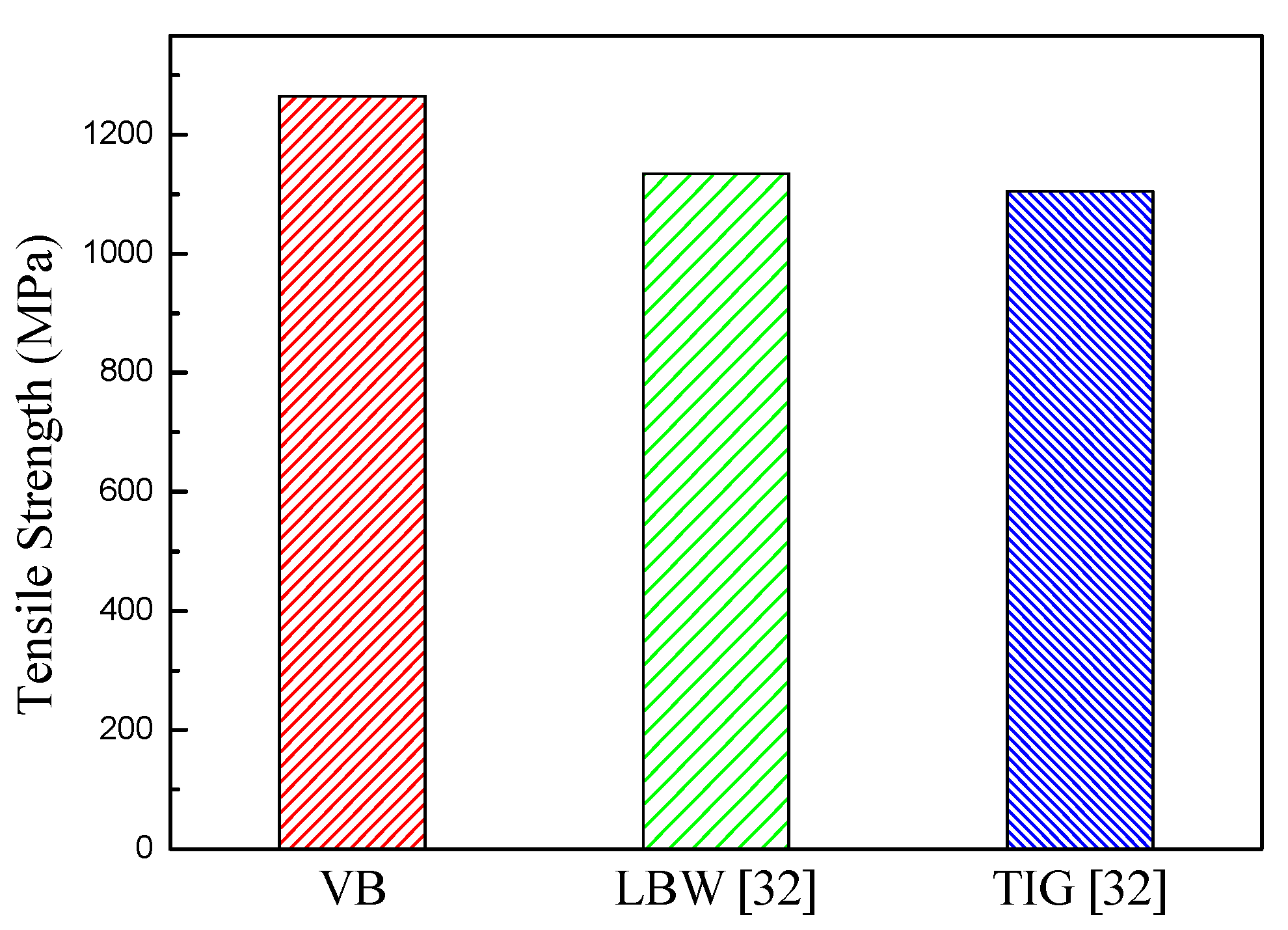
  • The predicted value of optimal tensile strength was 1262 MPa, with an error value of 0.24%. This demonstrates that the Taguchi method is a feasible means of obtaining the optimal process parameters of titanium vacuum brazed joints;
  • Under optimum process conditions, the base material of VB weldment is mainly composed of white granular α titanium, slender β titanium, and layered structures interlaced by α and β. The weld bead, composed of Ti-15Cu-15Ni, contains many slender needle-shaped Widmanstätten structures. These structures are commonly found in weld beads which use TiCuNi as a brazing filler and are associated with higher strength and lower ductility;
  • The specimen cross-section after vacuum brazing can be divided into three areas: base metal, diffusion zone, and weld bead. The microhardness value of the weld bead was the highest. The base material had the same microhardness as the annealing treatment, which was the lowest. The weld bead hardness of vacuum brazed parts is higher than that of laser beam weldment and gas tungsten arc weldment. The fracture section of the optimized specimens consists of dimples and small cleavage surfaces.

Author Contributions

Conceptualization, J.-R.H. and C.-D.H.; methodology, J.-R.H. and C.-D.H.; software, C.-D.H.; validation, C.-D.H.; investigation, C.-D.H.; resources, J.-Y.H.; data curation, C.-D.H. and J.-Y.H.; writing—original draft preparation, C.-D.H.; writing—review and editing, J.-R.H. and C.-D.H.; supervision, J.-R.H. All authors have read and agreed to the published version of the manuscript.

Funding

Ministry of Science and Technology, R.O.C. under the contract No. MOST 107-2221-E-008-071.

Data Availability Statement

Data presented in this article are available at request from the corresponding author.

Conflicts of Interest

The authors declare no conflict of interest.

References

  1. Balasubramanian, T.; Balasubramanian, V.; Muthumanikkam, M. Fatigue performance of gas tungsten arc, electron beam, and laser beam welded Ti-6Al-4V alloy joints. J. Mater. Eng. Perform. 2011, 20, 1620–1630. [Google Scholar] [CrossRef]
  2. Huang, X.; Richards, N. Activated diffusion brazing technology for manufacture of titanium honeycomb structures-a statistical study. Weld. J. 2004, 83, 73. [Google Scholar]
  3. Botstein, O.; Rabinkin, A. Brazing of titanium-based alloys with amorphous 25wt.% Ti-25wt.% Zr-50wt.% Cu filler metal. Mater. Sci. Eng. A 1994, 188, 305–315. [Google Scholar] [CrossRef]
  4. Elrefaey, A.; Tillmann, W. Effect of brazing parameters on microstructure and mechanical properties of titanium joints. J. Mater. Process. Technol. 2009, 209, 4842–4849. [Google Scholar] [CrossRef]
  5. Chang, C.; Du, Y.; Shiue, R.; Chang, C. Infrared brazing of high-strength titanium alloys by Ti-15Cu-15Ni and Ti-15Cu-25Ni filler foils. Mater. Sci. Eng. A 2006, 420, 155–164. [Google Scholar] [CrossRef]
  6. Ganjeh, E.; Sarkhosh, H. Microstructural, mechanical and fractographical study of titanium-CP and Ti-6Al-4V similar brazing with Ti-based filler. Mater. Sci. Eng. A 2013, 559, 119–129. [Google Scholar] [CrossRef]
  7. Chiou, C.-Y.; Shiue, R.-K.; Chang, C.S. Infrared brazing titanium alloys using clad Ti-15Cu-15Ni fillers with different clad layers. ISIJ Int. 2009, 49, 605–607. [Google Scholar] [CrossRef] [Green Version]
  8. Wu, Z.Y.; Yeh, T.Y.; Shiue, R.K.; Chang, C.S. The effect of substrate dissolution in brazing CP-Ti and Ti15-3 using clad Ti-15Cu-15Ni Filler. ISIJ Int. 2010, 50, 450–454. [Google Scholar] [CrossRef] [Green Version]
  9. Xia, Y.; Dong, H.; Li, P. Brazing TC4 titanium alloy/316L stainless steel joint with Ti50-xZrxCu39Ni11 amorphous filler metals. J. Alloy. Compd. 2020, 849, 156650. [Google Scholar] [CrossRef]
  10. Elrefaey, A.; Tillmann, W. Correlation between microstructure, mechanical properties, and brazing temperature of steel to titanium joint. J. Alloy. Compd. 2009, 487, 639–645. [Google Scholar] [CrossRef]
  11. Laik, A.; Shirzadi, A.; Tewari, R.; Kumar, A.; Jayakumar, T.; Dey, G. Microstructure and interfacial reactions during active metal brazing of stainless steel to titanium. Metall. Mater. Trans. A 2013, 44, 2212–2225. [Google Scholar] [CrossRef] [Green Version]
  12. Laik, A.; Shirzadi, A.; Sharma, G.; Tewari, R.; Jayakumar, T.; Dey, G. Microstructure and interfacial reactions during vacuum brazing of stainless steel to titanium using Ag-28 pct Cu alloy. Metall. Mater. Trans. A 2015, 46, 771–782. [Google Scholar] [CrossRef] [Green Version]
  13. Yue, X.; He, P.; Feng, J.; Zhang, J.; Zhu, F. Microstructure and interfacial reactions of vacuum brazing titanium alloy to stainless steel using an AgCuTi filler metal. Mater. Charact. 2008, 59, 1721–1727. [Google Scholar] [CrossRef]
  14. J-STAGE. Available online: https://www.jstage.jst.go.jp/article/jwstaikai/2012f/0/2012f_70/_article/-char/ja/ (accessed on 15 March 2022).
  15. Liu, S.; Suzumura, A.; Ikeshoji, T.-T.; Yamazaki, T. Brazing of stainless steel to various aluminum alloys in air. JSME Int. J. Ser. A Solid Mech. Mater. Eng. 2005, 48, 420–425. [Google Scholar] [CrossRef] [Green Version]
  16. Tamai, F.; Hirano, K. Characteristics of static and fatigue strength of alumina ceramic joints. JSME Int. J. Ser. A Mech. Mater. Eng. 1996, 39, 613–619. [Google Scholar] [CrossRef] [Green Version]
  17. Shiue, R.-K.; Wu, S.-K.; Liu, C.-K.; Dai, C.-Y. Interfacial reaction and bonding strength of Ti50Ni50 and Inconel 600 dissimilar brazed joints. Mater. Trans. 2017, 58, 1308–1312. [Google Scholar] [CrossRef] [Green Version]
  18. AlHazaa, A.; Haneklaus, N. Diffusion bonding and transient liquid phase (TLP) bonding of type 304 and 316 austenitic stainless steel—A review of similar and dissimilar material joints. Metals 2020, 10, 613. [Google Scholar] [CrossRef]
  19. Liaw, D.W.; Wu, Z.Y.; Shiue, R.K.; Chang, C.S. Microstructural analysis of infrared brazed Ti-6Al-4V and Nb using the Ti-15Cu-25Ni foil. ISIJ Int. 2007, 47, 869–874. [Google Scholar] [CrossRef] [Green Version]
  20. Elrefaey, A.; Tillmann, W. Brazing of titanium to steel with different filler metals: Analysis and comparison. J. Mater. Sci. 2010, 45, 4332–4338. [Google Scholar] [CrossRef]
  21. J-STAGE. Available online: https://www.jstage.jst.go.jp/article/denkiseiko/74/4/74_4_267/_article/-char/ja/ (accessed on 15 March 2022).
  22. Yan, G.; Tan, M.J.; Crivoi, A.; Li, F.; Kumar, S.; Chia, C.H.N. Improving the mechanical properties of TIG welding Ti-6Al-4V by post weld heat treatment. Procedia Eng. 2017, 207, 633–638. [Google Scholar] [CrossRef]
  23. Karna, S.K.; Sahai, R. An overview on Taguchi method. Int. J. Eng. Sci. Math. 2012, 1, 11–18. [Google Scholar]
  24. Qazi, M.I.; Abas, M.; Khan, R.; Saleem, W.; Pruncu, C.I.; Omair, M. Experimental investigation and multi-response optimization of machinability of AA5005H34 using composite desirability coupled with PCA. Metals 2021, 11, 235. [Google Scholar] [CrossRef]
  25. Kuo, C.-H.; Lin, Z.-Y. Optimizing the high-performance milling of thin aluminum alloy plates using the Taguchi method. Metals 2021, 11, 1526. [Google Scholar] [CrossRef]
  26. Lin, H.; Hwang, J.-R.; Fung, C.-P. Fatigue properties of 6061-T6 aluminum alloy T-joints processed by vacuum brazing and TIG welding. Mater. Trans. 2016, 57, 127–134. [Google Scholar] [CrossRef] [Green Version]
  27. Liu, S.; Miao, J.; Zhang, W.; Wei, R.; Chen, C.; Wang, T.; Zhao, W.; Jing, Z.; Li, F. Interfacial microstructure and shear strength of TC4 alloy joints vacuum brazed with Ti-Zr-Ni-Cu filler metal. Mater. Sci. Eng. A 2020, 775, 138990. [Google Scholar] [CrossRef]
  28. Pang, S.; Sun, L.; Xiong, H.; Chen, C.; Liu, Y.; Li, H.; Zhang, T. A multicomponent TiZr-based amorphous brazing filler metal for high-strength joining of titanium alloy. Scr. Mater. 2016, 117, 55–59. [Google Scholar] [CrossRef]
  29. Xia, Y.; Dong, H.; Hao, X.; Li, P.; Li, S. Vacuum brazing of Ti6Al4V alloy to 316L stainless steel using a Ti-Cu-based amorphous filler metal. J. Mater. Process. Technol. 2019, 269, 35–44. [Google Scholar] [CrossRef]
  30. Wu, B.; Li, J.; Tang, Z. Study on the electron beam welding process of ZTC4 titanium alloy. Rare Metal Mat. Eng. 2014, 43, 786–790. [Google Scholar] [CrossRef]
  31. Zhang, H.-H.; Cui, Z.-D.; Zhu, S.-L.; Guo, S.-W.; Yang, X.-J.; Inoue, A. Microstructure and mechanical properties of TC4 joints brazed with Ti–Zr–Cu–Sn amorphous filler alloy. Rare Metals 2021, 40, 1881–1889. [Google Scholar] [CrossRef]
  32. Gao, X.-L.; Zhang, L.-J.; Liu, J.; Zhang, J.-X. A comparative study of pulsed Nd: YAG laser welding and TIG welding of thin Ti6Al4V titanium alloy plate. Mater. Sci. Eng. A 2013, 559, 14–21. [Google Scholar] [CrossRef]
  33. Keist, J.S.; Palmer, T.A. Development of strength-hardness relationships in additively manufactured titanium alloys. Mater. Sci. Eng. A 2017, 693, 214–224. [Google Scholar] [CrossRef] [Green Version]
  34. Zou, Z.; Zeng, F.; Wu, H.; Liu, J.; Li, Y.; Gu, Y.; Yuan, T.; Zhang, F. The joint strength and fracture mechanisms of TC4/TC4 and TA0/TA0 brazed with Ti-25Cu-15Ni braze alloy. J. Mater. Eng. Perform. 2017, 26, 2079–2085. [Google Scholar] [CrossRef]
Figure 1. Configuration of the butt joint in vacuum brazing (all dimensions in mm).
Metals 12 00974 g001
Figure 2. Specimens put in the (a) graphite jig, and (b) the center of the vacuum furnace with jig.
Metals 12 00974 g002
Figure 3. Vacuum brazing process: A: soaking temperature; B: soaking time; C: brazing temperature; D: brazing time.
Metals 12 00974 g003
Figure 4. The notched tensile test specimen.
Metals 12 00974 g004
Figure 5. Main effects of the S/N ratios.
Metals 12 00974 g005
Figure 6. Predicted and experimental values of the optimal tensile strength.
Metals 12 00974 g006
Figure 7. Metallographic microstructure of the Ti-6Al-4V base metal after vacuum brazing.
Metals 12 00974 g007
Figure 8. Microstructures around the weld bead of Ti-6Al-4V vacuum brazing. (I—base metal; II—diffusion layer; III—weld bead).
Metals 12 00974 g008
Figure 9. Microhardness distribution of A3B3C1D3 specimen.
Metals 12 00974 g009
Figure 10. Comparison of Tensile Strength of VB, TIG, and LBW.
Metals 12 00974 g010
Figure 11. Fractograghs of vacuum brazed specimens showing (a) the initial fracture position and (b) the ductile fracture dominated by dimples.
Metals 12 00974 g011
Table 1. The constituent elements of the base and filler metals (wt.%).
MaterialAlVCrFeNiTiCuNi
Ti-6Al-4V5.883.6000.080.08Bal.00
TiCuNi00000701515
Table 2. Technical specifications of the vacuum brazing furnace.
Specifications of the Vacuum Brazing Furnace
Chamber Size (mm)600 (W) × 600 (H) × 900 (L)
Vacuum Level (torr)Up to 5 × 10⁻⁵
Operation Temperature Range (°C)From 350 to 1250
Maximum Loading Weight (kgf)Up to 500
Table 3. Control factors and their levels in vacuum brazing.
LevelControl Factor
ABCD
Soaking
Temperature
(°C)
Soaking
Time
(min)
Brazing
Temperature
(°C)
Brazing
Time
(min)
18503097515
28704599030
390060100545
Table 4. Orthogonal array L9 (34) of experimental data and S/N ratios.
TrialSpecimen
ID
Control Factor and LevelTensile Strength (MPa)S/N Ratio
(dB)
ABCDNo. 1No. 2No. 3
1T1111111031075108960.73
2T212221073957102460.09
3T3133311171130113261.03
4T4232111671115113161.12
5T52132989109096560.09
6T6221311331253113061.35
7T7323111631160113961.24
8T8331211441128111561.05
9T9312312241209125861.80
Table 5. Response table for the S/N ratios.
LevelControl Factor
ABCD
160.61960.87561.04761.032
260.85260.89361.00060.410
361.36461.06760.78961.393
Delta0.7450.1920.2580.983
Rank2431
Table 6. Response table of signal-to-noise ratio and ANOVA analysis for tensile strength.
Control FactorDFSSTSSEMSTMSEFPi (%)
Soaking Temperature, A20.8711.6640.4360.2771.57127.7
Soaking Time, B21.4821.0480.7410.1754.24347.3
Brazing Temperature, C20.1132.4220.0570.4040.1403.6
Brazing Time, D20.6732.4670.0340.4110.08221.4
Total83.139----100
Table 7. Verification of the optimization of tensile strength.
Specimen
(A3 B3 C1 D3)
Tensile Strength (MPa)
11302
21224
31268
Mean1265
Predicted1262
Error3
Publisher’s Note: MDPI stays neutral with regard to jurisdictional claims in published maps and institutional affiliations.

