Article

Effect of Grain Orientation on Hydrogen Embrittlement Behavior of Interstitial-Free Steel

1
Corrosion and Protection Center, Institute for Advanced Materials and Technology, University of Science and Technology Beijing, Beijing 100083, China
2
NCS Testing Technology Co., Ltd., Beijing 100083, China
*
Author to whom correspondence should be addressed.
Metals 2022, 12(6), 981; https://doi.org/10.3390/met12060981
Submission received: 12 April 2022 / Revised: 26 May 2022 / Accepted: 27 May 2022 / Published: 7 June 2022
(This article belongs to the Section Metal Failure Analysis)

Abstract

:
In interstitial-free (IF) steel with a certain microtexture, the micro-orientation of grains is essential to understand the occurrence of hydrogen-induced cracking in body-centered cubic (BCC) structural steels. In this study, the hydrogen embrittlement (HE) susceptibility of IF steels was determined by slow strain rate tensile (SSRT) tests and hydrogen microprinting (HMT) experiments from the perspective of crystal orientation. The strength of the specimen with hydrogen was slightly higher than that without hydrogen, while the ductility and toughness were drastically reduced by hydrogen charging during the SSRT test. The HE susceptibility was characterized by the loss of elongation (Iδ) and toughness (Iψ), with losses of 46.3% and 70%, respectively. The microstructural observations indicate that cracks initiated along grains oriented in the {100} || normal direction (ND), and grain boundaries (GBs) around {100}||ND were prone to be enriched in hydrogen atoms; that is, {100} || ND showed poor resistance to intergranular cracking and susceptible to hydrogen segregation. HMT was used to confirm the above viewpoints. Meanwhile, the statistical results showed those high-angle misorientations of 50–60° deviation are the locations most vulnerable to fracture.

1. Introduction

Interstitial-free (IF) steel is a type of ultralow carbon steel with a certain amount of titanium and/or niobium added to fix the interstitial C and N atoms. It is widely used in the automobile industry because of its excellent deep-drawing performance. IF steel is not as susceptible to hydrogen embrittlement (HE) as high-strength steel due to its low strength. Usually, the matrix of high-strength steel is a martensitic structure with high dislocation density or even more precipitation phases [1,2,3]. It is precisely because of such structural characteristics that there will be many stress or strain concentration sites in the material [4,5]. This makes it easy for hydrogen to accumulate at the stress concentration and leads to the dangerous behavior of brittle fracture [6,7,8,9]. On the other hand, the microstructure of IF steel is a pure body-centered cubic (BCC) structure with low dislocation density and few precipitates, so its strength is usually low. Consequently, such structural characteristics are just suitable for studying the intrinsic effect of hydrogen on the grain orientation of the BCC structure without being affected by other defects or stress concentrations (such as dislocations or precipitates). However, Liu et al. [10] reported the HE susceptibility of IF steel to hydrogen, which was based on a cold-deformed sample, and the HE susceptibility was improved slightly. This indicates that HE in IF steel is also worthy of attention. In fact, some other studies also focused on the HE of low-carbon steels [11,12]. HE can affect the mechanical properties of steel in a variety of ways, leading to reductions in the mechanical strength, toughness and ductility, as well as subcritical crack growth [13]. Therefore, research on the HE behavior of IF steel will provide a reference value for the further development of automotive steel. The slow strain rate tensile test (SSRT) [14,15] is often performed by scholars to study the HE of steels, because there is sufficient time for hydrogen to diffuse into the interior of the sample during this process.
It is known that the HE behavior of steel is microstructure-susceptible. Although IF steel has the single-phase BCC structure of ferrite, which is relatively less sensitive to hydrogen than martensite, there are two types of microstructural characteristics in IF steel: the microtexture and grain boundary (GB) character. The microtexture usually affects the local deformation character and fracture behavior. In the HE field, Masoumi [16,17,18,19,20,21,22] studied a variety of steels with respect to the relationship between hydrogen-induced cracking and the microtexture. In the study of Fe-Co-Ni high-strength steel [18] and low-carbon steel [19], a similar conclusion was obtained; that is, {100} || normal direction (ND)-oriented grains were prone to hydrogen-induced cracking (HIC) initiation, and grains with a high Taylor factor facilitated crack propagation, while {110} and {111} grains were crack-free areas. Venegas et al. [23,24] reported that the preferentially oriented grains of {111} || ND in API X46 steel improved the HIC resistance. Ghosh et al. [25] also showed that the cleavage of {100} || ND grains produced by austenite grain recrystallization and ferrite transformation provides a path that easily fractures and significantly reduces the mechanical properties and resistance to HIC. However, the effect of the microstructure on the HE behavior of IF steel with an obvious microstructure has not been reported thus far. With respect to GBs, they are usually regarded as reversible hydrogen traps, which promote the occurrence of HE. As hydrogen traps, GBs play an important role in hydrogen capture. Large-misorientation GBs with high energy storage provide an easier method for crack propagation. The energy of the coincident site lattice (CSL) is lower and more stable, and the exponent of the CSL is higher, which can hinder crack propagation [26,27]. Our previous research [28] discussed the optimal microstructural characteristics for improving the intergranular corrosion resistance of twinning-induced plasticity (TWIP) steel from the perspective of GB, and GB design based on fractal theory provides a promising solution to optimize the corrosion behavior of materials by analyzing complex GB networks. While in Matteo’s study [29], they concluded that Σ3 coherent twin boundaries are preferential crack initiation sites, how the GB type affects the occurrence of HE in IF steel has rarely been reported.
The occurrence of the HE behavior of metals is the result of local hydrogen enrichment, which can promote the initiation of HICs. If the local enrichment of hydrogen can be directly characterized, the relationship between the distribution of hydrogen and the microstructure can be determined to a certain extent to provide a reference for improving the anti-HE of materials by regulating the microstructural characteristics. The hydrogen microprint technique (HMT) is a powerful method for qualitatively characterizing the distribution of hydrogen. HMT is a simple and effective method to explore the microscopic distribution of hydrogen in materials. Although hydrogen cannot be quantified by HMT, it provides the basic characteristics and spatial distribution information of hydrogen released directly from the alloy after charging with hydrogen. Many scholars have used HMT to study hydrogen enrichment at GBs, phase boundaries, inclusions, crack propagation, etc., under hydrogen charging conditions or applied stress conditions to help explain the HE mechanism and visualize diffusion and hydrogen enrichment [7,8,30,31,32,33,34,35,36,37]. For example, Momotani et al. [7,8] studied the HE behavior of low-carbon martensitic steels with HMT, indicating that hydrogen aggregates at GBs at low strain rates and leads to intergranular cracking, while hydrogen is uniformly distributed at a high strain rate, resulting in transgranular cracking. Ovejero-García used HMT to observe 304 stainless steels after hydrogen charging, showing hydrogen enrichment at the GBs and C/Cr compounds [31]. Chen [32] studied 2205 duplex steel by HMT and suggested that the hydrogen permeation rate and effective diffusivity in the ferritic phase are higher than in the austenitic phase, and more hydrogen distribution in the ferritic phase can be detected by HMT. HMT is also applicable to the study of the HE susceptibility of IF steel. We studied the correlation between hydrogen distribution and grain orientation. Furthermore, the effect of grain orientation on HE was explored.
In this work, the HE behavior of IF steel samples was systematically evaluated from the perspective of hydrogen enrichment. The dependence of HIC on the microstructure of IF steel was investigated with regard to the microscopic texture and GB characteristics. To this end, scanning electron microscopy (SEM), electron backscatter diffraction (EBSD), and HMT were used to characterize the HE behavior of IF steel.

2. Materials and Methods

A commercially available cold-rolled and annealed IF steel plate (designated as DC04) with an approximate thickness of 1 mm was used for all tests. Specimens were cut from the steel plate, heated at 850 °C for 1 h, and then furnace cooled. Hence, γ-fiber ({111}<uvw> fiber texture) recrystallization textures form, and two theories mentioned elsewhere [38,39,40,41] are usually used to explain the development of strong γ-fiber recrystallization textures in IF steels. The formation of textures in steel is influenced by its alloy chemistry as well as by processing parameters such as finishing temperature during hot rolling, coiling temperature, amount of cold reduction, annealing temperature and time [40,41]. The chemical composition of the as-received material is shown in Table 1.
Several specimens were in a recrystallized state with a mean grain size of about 35 μm.

2.1. Hydrogen Diffusion Coefficient

The diffusion coefficient (DH) was calculated based on electrochemical hydrogen permeation tests. The modified “Devanathane-Stachurski cell” [42], which was proposed elsewhere, was used to perform the hydrogen permeation test here. Specimens were mechanically polished using metallographic sandpaper with a particle size of # 300 to # 5000 in order to reduce the thickness to 0.8 mm. Subsequently, specimens were fixed between two compartments of a double electrolytic cell. The electrolyte solution for hydrogen charging was composed of 0.2 M NaOH + 0.22 g/L CH4N2S with a current density of 1 mA/cm2. The electrolyte solution for hydrogen desorption was composed of 0.2 M NaOH with an open-circuit potential (OCP) plus 0.25 V. The hydrogen desorption surface was an electroplated nickel layer with a thickness of 100 nm. DH can be calculated from the following equation [43]:
DH = L2/6t0:63
where L is the thickness of the specimen, and t0.63 is 0.63 times the saturation current corresponding to the time.

2.2. Slow Strain Rate Tensile Test

Tensile specimens with a gauge section of 20 mm × 5 mm × 0.8 mm and grip sections on both ends were machined parallel to the rolling direction (RD). The tensile test was carried out at an ambient temperature of approximately 294 K at a 1 × 10⁻⁶ s−1 strain rate (corresponding to a crosshead speed of 1.2 × 10⁻³ mm min−1) along the RD. The schematic of the hydrogen charging setup during SSRT was given in our earlier study [14]. Hydrogen was continuously introduced into the specimens during the tensile tests by electrochemical charging in a 0.1 mol/L NaOH aqueous solution at a current density of 30 mA/cm2 until the specimen broke. A platinum wire was used as the counter electrode. The solution was added continuously to cover the gauge part of the sample during the entire test. Tensile tests at the same strain rate in air were conducted to compare with the SSRT test. HE susceptibility is characterized by the loss of the elongation (Iδ) and reduction in the section (Iψ), as follows.
Iδ = (δAirδH)/δAir × 100%
Iψ = (ψAirψH)/ψAir × 100%
where δAir/ψAir and δH/ψH are the total elongation (TEL)/reduction of the section of the hydrogen-uncharged and hydrogen-charged specimens, respectively. When the specimen was broken, one side was mechanically polished and then etched with 4% nitric acid alcohol for 45 s for EBSD observation.

2.3. Hydrogen Microprint Technique Method Test

The in situ hydrogen-charged HMT specimen size was 10 mm × 10 mm × 0.8 mm. The results of hydrogen-free and hydrogen charging for 6 h were obtained for comparison. The hydrogen charging side was only mechanically ground, while the other side was polished and then etched with 4% nitric acid alcohol for 45 s, and finally, this side was coated with a photosensitive emulsion. The HMT test was carried out in a darkroom, and a photosensitive emulsion containing AgBr particles and gelatin was uniformly coated on one surface of the sample so that a redox reaction between hydrogen and AgBr occurred, as shown in Equation (4).
Ag+ + H = Ag + H+
First, the photosensitive emulsion needs to be heated in a hot water bath at 45~55 °C to become liquid, but a water bath with too high a temperature will destroy the emulsion’s nature. The emulsion was diluted with 10% NaNO2 and water at a ratio of 1:2:4. NaNO2 was added to prevent pseudophotography [31]. Then, the wire-loop method mentioned by Yalcí and Ronevich [33,34] with a φ0.2 mm metal wire was used to dip the AgBr solution to make a thin slurry film. Due to the surface tension of the solution, the film was suspended within the loop and deposited a uniform emulsion layer on the steel sample surface (the etched side). During drying, a hydrogen charging test was carried out on the back side of the sample. A schematic diagram of the charging setup is shown in Figure 1. Following exposure (the exposure process is actually the reaction of Equation (4)) for 6 h, the steel was placed in a solution of 10% NaNO2 and 15% Na2S2O3 to fix for 15 min, rinsed with clean water for 5–10 min [35], and dried.
The hydrogen charging parameters of HMT were the same as those in the tensile test process in Section 2.2, while hydrogen was charged for 6 h.

2.4. Microstructural Characterization

The macrotexture was determined by X-ray diffraction (XRD: UItima IV, RIGAKU, Tokyo, Japan). Orientation distribution functions (ODFs) of the global structure were calculated based on the series expansion method proposed by Roe [44] from three incomplete pole figures of {200}, {110}, and {211} and expressed using φ2 = 45° ODF sections.
The fracture surfaces and surface crack morphologies of tensile specimens were observed by field-emission scanning electron microscopy (FE-SEM; ZEISS DSM, Jena, Germany) at 20 kV and an 11–13 mm working distance.
The surface cracks of the fractured specimens were characterized after the SSRT test by using EBSD. It was carried out on an Oxford channel 5 system, which was connected to a Zeiss Auriga scanning electron microscope (Jena, Germany), working at a 20 kV accelerating voltage, 70° sample tilt angle, 17 mm working distance and 0.5 μm step length. Finally, the EBSD data were treated with Channel 5 software (Oxford Instruments NanoAnalysis, High Wycombe, UK).

3. Results

3.1. Microstructure of IF Steel

An ODF of φ2 = 45° was obtained by XRD, as shown in Figure 2a, and Figure 2b shows the inverse pole figure (IPF) image of the RD-TD surface of as-received IF steel. For simplicity, the orientation is classified into three groups: near-{100}, near-{110}, and near-{111}. It can be seen from Figure 2b that the equiaxed grains are dominant. Furthermore, {111} fiber occupies most of the investigated area. According to the XRD results, we can calculate the percentage composition of the γ texture, which is up to 78.7%, and the results are listed in Table 2. The orientation within a tolerance of 15° was defined for each low-index orientation since the higher the content of γ, the lower the percentage of the other orientations.

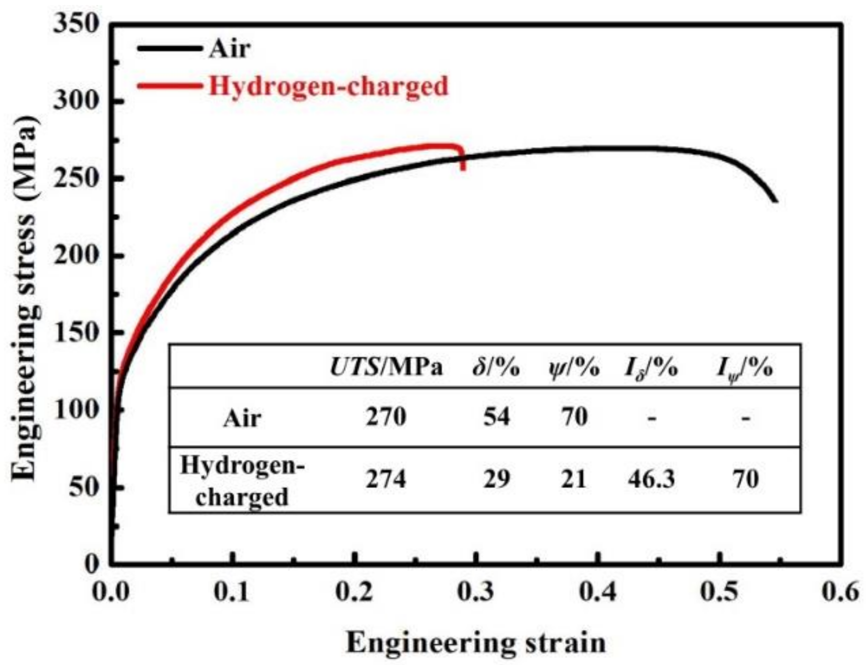
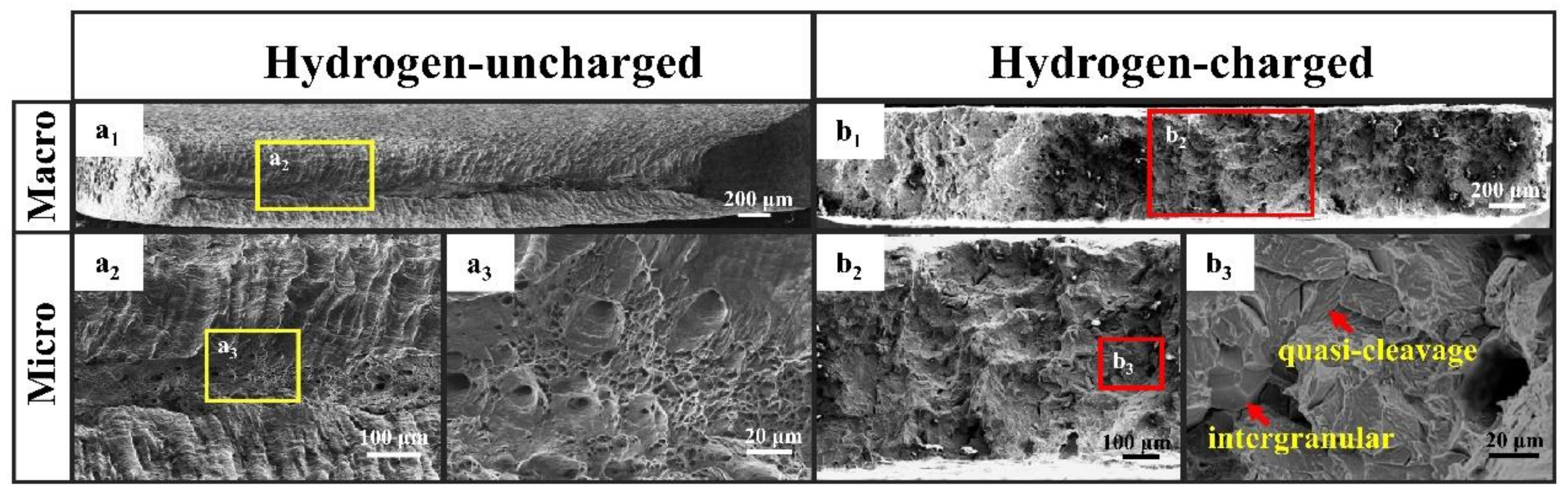
3.2. Mechanical Properties and HE Susceptibility

Three specimens were respectively taken from the two groups of SSRT tests, and the average values were used to obtain the engineering stress-strain curves shown in Figure 3, in which the mechanical properties are also shown. When the specimen was tensiled at a 1 × 10⁻⁶ s−1 strain rate, hydrogen had sufficient time to diffuse and gather in the region with stress concentration under the stress-induced effect. It can be seen in Figure 3 that the ultimate tensile strength (UTS) increased slightly after hydrogen charging, while the elongation to fracture and reduction in the section deteriorated drastically. The HE susceptibility indices Iδ and Iψ were calculated to be 46.3% and 70%, respectively. That is, the HE susceptibility of IF steel was reflected in decreases in plasticity and toughness. This is different from the HE susceptibility of high-strength steel. The introduction of hydrogen generally increases the strength of high-strength steel, while the elongation decreases and presents strong brittleness. Allen’s study of dual-phase (DP) steel and transformation-induced plasticity (TRIP), specifically in TRIP-assisted bainitic ferrite (TBF) steels [36], concluded that the strength of the material after hydrogen charging is essentially constant, but the diffusible hydrogen entering the matrix reduces the ductility, and each ductility level can be equated to the diffusible hydrogen concentration.
Figure 4 shows the fracture morphology after the SSRT test in air and with hydrogen charging. As shown in Figure 4(a1), the edge of the fracture when stretching in air was a shear lip, and the center was a dimple region. As shown in Figure 4(b1,b3), the fracture after the SSRT test with hydrogen was characterized by intergranular fracture and cleavage or quasi-cleavage (as the red arrows point to), which is classified as brittle fracture.

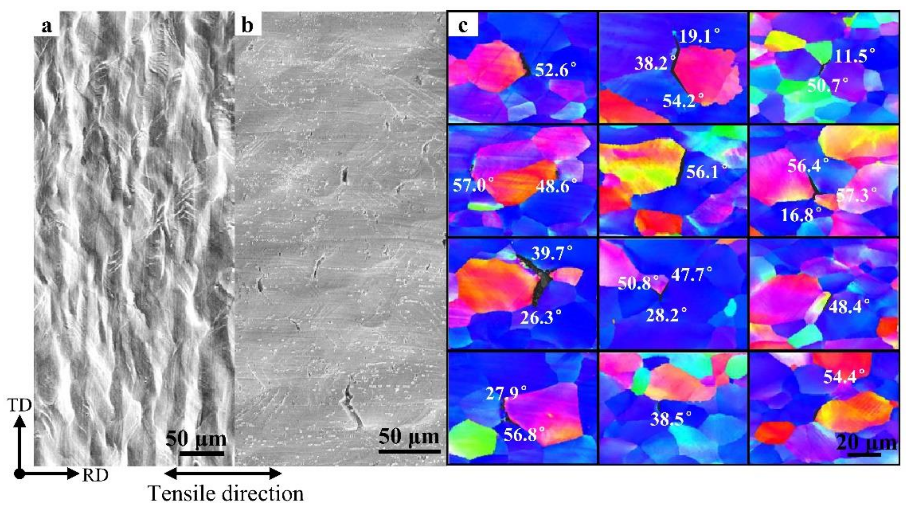
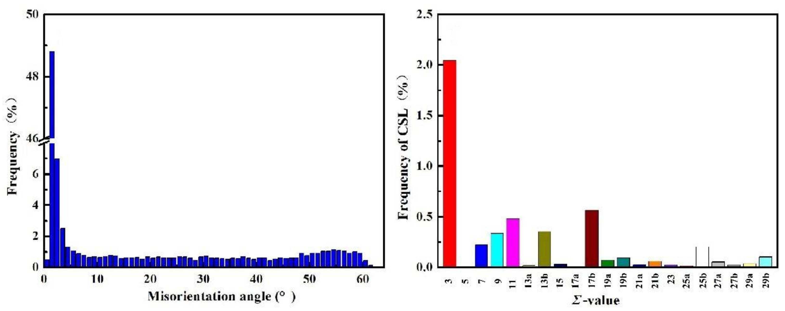
3.3. Orientation Statistics of Hydrogen-Induced Microcracks

SEM and EBSD were used to detect the surface cracks of the specimens. SEM images on the surface of several specimens deformed in air showed no cracks, but only shear or slip bands were observed on the surface, as shown in Figure 5a. However, there were some short cracks on the surface of the specimens after the SSRT test with hydrogen charging, almost all of which were perpendicular to the tensile direction, and most of them were intergranular cracks (ICs). The characteristics of the ICs were statistically analyzed, and the misorientation on both sides of each crack was determined, as shown in Figure 5b,c. Figure 5a,b show the crack distribution and morphology at low magnification, and the field of view is approximately 800 μm from the fracture surface. A total of approximately 60 SEM images of the field of view were counted to analyze the cracks, and there was at least one crack in each field of view. Figure 5c shows 12 random crack fields, where the crack morphology and the misorientation on both sides can be clearly seen.
As seen in Figure 6, low-angle GBs and Σ3 each account for approximately 50% and 2% in the original specimen. High-angle misorientations of 50–60° are 10.7%.
Statistical analysis of misorientation angles was performed for all cracks at intervals of 10°, and the proportions of various orientation difference ranges at the cracking point are shown in Figure 7. There was a 37.7% fracture ratio at high-angle misorientations of 50–60°. High-angle misorientations with hydrogen charging are easily fractured, while low-angle and Σ GBs have difficulty fracturing or hinder crack propagation. It can be seen from this study that the GBs with a high-angle misorientation of 50–60° in IF steel are most likely to crack. Combining Figure 6 and Figure 7, we learn that the probability of HIC is about approximately 4% for GBs of 50–60°.
In addition, these ICs in IF steels were formed with orientation dependence, and the analyzed results are presented in Table 3 for the case of intergranular cracking with low-index orientation. The surface area of the specimen selected for detecting surface cracks was approximately 4.3 mm (the width of the fractured specimen) × 1 mm (from the fracture surface to 1000 μm away). Since the average grain size of the specimen is approximately 35 μm, we can calculate the average numbers of grains for each low-index orientation according to Table 2, and the results are shown in Table 3. The number of grains in the detected area is approximately 3510. The ratio of these low-index orientations is expressed by the number of grains, and then the number of cracks is compared based on the number of grains.
It is believed that the crack belongs to both sides. For example, the crack fractured along {100} and {111} || ND-oriented grains belongs to both {100} and {111} || ND grains.
The number of ICs along the {100} || ND-orientated grains is approximately 96.4/103 grains, and the fracture probability is much higher than that in the other orientations. Since the {100} || ND grains did not provide a sufficient slip system during the deformation process and the {111} grains were close to the close-packed plane in the BCC structure, local plastic deformation was reduced by promoting dislocation motion; these were the factors that led to the increased crack resistance of the sample [17].
To further analyze the nature of the microcrack of the specimen when hydrogen is introduced, EBSD was conducted, as shown in Figure 8. Figure 8a,b display two typical ICs, respectively. As shown in Figure 8(a2), the cracks were arrested at the Σ3 GB.
Figure 8(a4,b4) reveal the distribution of the Taylor factor in the sample. The colors represent Taylor factor numbers. The calculation of the Taylor coefficient is based on the assumption that the local deformation of grains is the same as the macroscopic deformation, while the plastic deformation is completely caused by dislocation slip. The Taylor coefficient M is defined as [45]:
M = σx/τ = /dεx
In the formula, σx is the normal stress in the polycrystal, εx is the normal strain, τ is the shear stress, and γ is the shear strain. The Taylor factor represents the ability of the crystal to resist plastic deformation, and it is a function of both the grain orientation and external stress field. The greater the Taylor factor is, the more slip required for deformation and the greater deformation work consumed, which means that deformation is difficult. The test results show that the Taylor factor of {111} || ND grains is generally high (>3), and such grains do not easily deform and fracture in IF steels. Therefore, only a few ICs were located at the junction of {111} and {111} grains in statistical cracks. For {100} || ND, the crack location was usually located where the Taylor factor value of the grain was 3 or less, as shown in Figure 8(a4,b4).
In addition, the {110} || ND orientation is rare in IF steel, and it does not show consistent characteristics in the case of crack statistics, which is not representative.

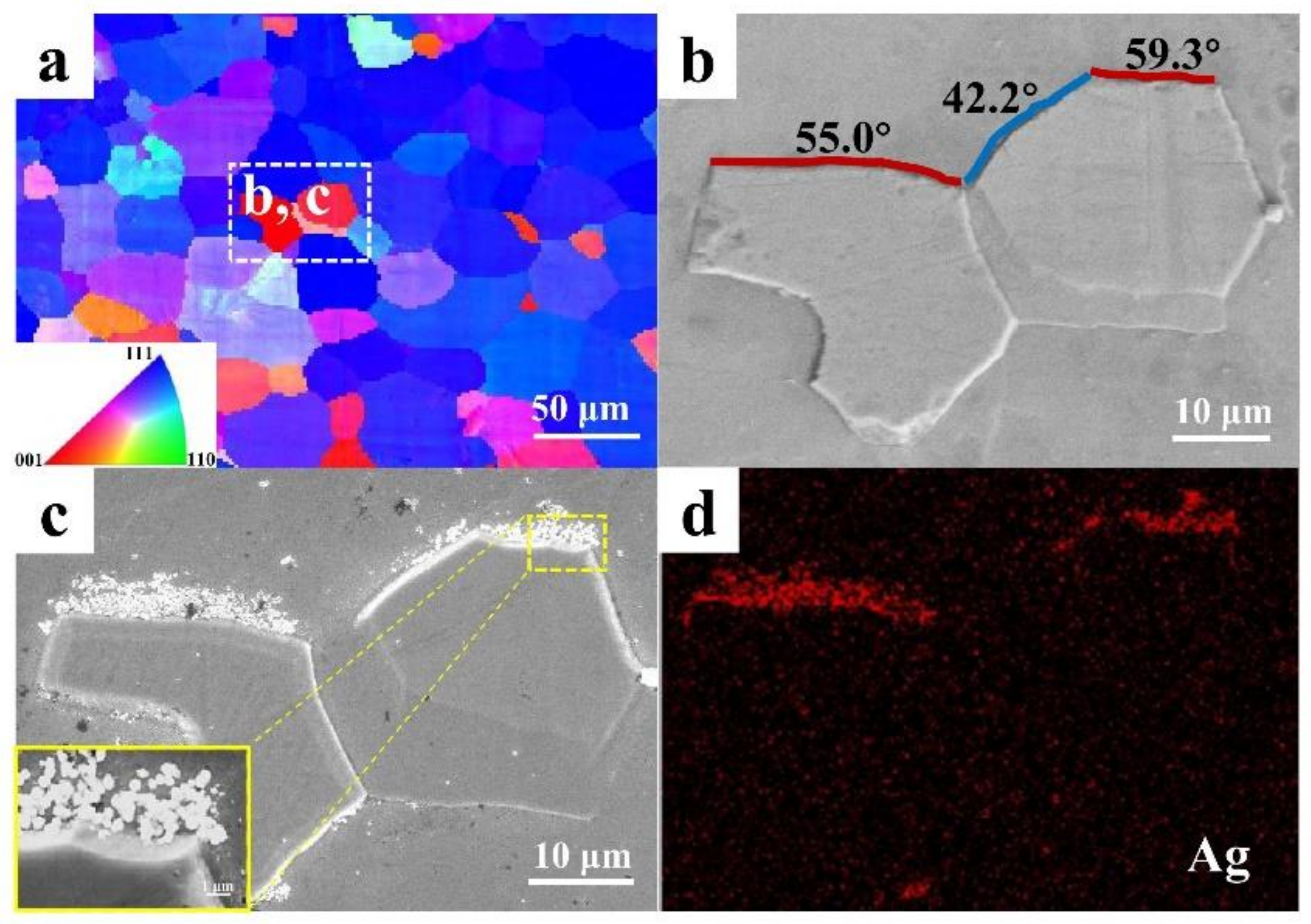
3.4. The HMT Results of Hydrogen-Induced Microcracks

The DH calculated from Equation (1) is 5.7 × 10⁻⁷ cm2/s; thus, it can be known that the double-side hydrogen charging time of the specimen is approximately 94 min.
The in situ results of specimens without hydrogen and after hydrogen charging with HMT for 6 h are shown in Figure 9. The white dotted box in the IPF diagram (Figure 9a) corresponds to Figure 9b,c. The misorientations marked in Figure 9b are 55.0°, 42.4°, and 59.3°. Figure 9d is the energy-dispersive X-ray spectroscopy (EDS) composition surface distribution results of Ag after hydrogen charging for 6 h, which completely corresponds to Figure 9c. When the specimen was hydrogen charged for 6 h, Ag particles significantly gathered only at 55.0° and 59.3° among the GBs of the three misorientations marked in Figure 9b, and Ag preferred to concentrate around the {100} || ND orientation. This further verifies the conclusion in Section 3.2 that {100} || ND is the brittle orientation in IF steel, and high-angle GBs of 50–60° are the most susceptible to hydrogen.

4. Discussion

4.1. The Orientation Dependence of HE Susceptibility

When a polycrystalline material is subjected to deformation, slip first occurs in grains aligned with the direction of the load axis. Once the neighbor grains are arranged in an unfavorable orientation for slip and local load increases, it results in intergranular microstrain [46]. The limited slip bands around the crack initiation points limit the deformation of the grains; subsequently, the movement of dislocations is hindered, and “pile-up” occurs at obstacles, such as high-angle GBs. When the material’s strain-hardening limit is reached around the crack-potential region, microcracks tend to occur. The tensile stress facilitates crack growth through the increase in stress concentration at structural defects. Figure 8(a1,a3,b1,b3) show that the crack propagates along the {100} || ND (or near the {100} || ND) orientation since hydrogen segregates around these grains in the hydrogen-charged IF specimens. Due to the symmetry of the cubic lattice, diffusion in almost any direction is allowed, but surface energy differs depending on orientation. Tran et al. [47] presented three low-index orientations of surface energy, whose order of magnitude is {100} < {110} < {111}. The {100} grains have a higher hydrogen flux as a result of their lower energy barrier. The diffusion on GBs is asymmetric because of the difference in surface energies. In Xie’s study [48], it was proved that the surface energies of various crystal orientations play an important role in the evolution of hydrogen blisters. Additionally, the {100} planes in BCC material have the largest atomic distance and the smallest atomic compressive energy and bonding energy, known as the cleavage plane of crack propagation [49]. Thus, it is further proven that the {100} orientation in IF steel is the brittle orientation. Nondense {100} planes with the maximum atomic spacing have a preferred site for causing crystalline microdefects. In steel, carbon and nitrogen with smaller atomic radii tend to occupy the octahedral position in the BCC lattice [50]. Lattice distortion in such a structure leads to the weakening of covalent atomic bonds, especially in the {100} planes, with a small number of nearest-neighbor atoms and a low packing density. Therefore, {100}-oriented grains are prone to fracture and fail [51]. Moreover, the crack propagates along grains oriented with {001} || ND, and the lack of a sufficient slip system adversely affects the corrosion resistance of HIC. On the other side, grains oriented with {111} and {110} correspond to the dense plane in the BCC structure, showing high corrosion resistance [19,23].
The surface energies of iron atom crystal lattice orientations were given by Tran et al. [47]. The initial hydrogen flux of {111} grains is slower, which can be explained by the higher energy barrier of hydrogen emission from the steel due to the higher surface energy of this orientation. Another characteristic of grains oriented in {111} || ND is that they can accumulate a large plastic deformation when cracks are close enough to each other, leading to interaction and coalescence [30]. The lattice in these grains is able to rotate along the direction of maximum shear stress in the crack interaction zone, causing them to suffer greater plastic deformation during the process. This deformation reduces the driving force of the interaction crack growth, thereby improving the resistance of the steel to HIC and reducing the probability of closely spaced non-coplanar crack coalescence [30,52]. In addition to orientation characteristics, another factor leading to uneven hydrogen distribution is the GB, as the specimens are recrystallized and annealed. It is believed that high-angle GBs with high disorder between neighboring grains and vacancies are effective hydrogen trapping sites. High-angle boundaries can provide an easier path to crack nucleation and propagation due to their high lattice distortion and high stored energy. In addition, it is considered that higher misorientation leads to an increase in internal stress. Since hydrogen accumulation is a prerequisite for HIC, hydrogen will accumulate according to a stress-induced hydrogen diffusion mechanism [53]; as a result, high-angle GBs more easily arrest hydrogen and are more susceptible to crack nucleation and propagation. There is a high local strain field at or near GBs due to the pile-up of dislocations during plastic deformation. GB sliding is restricted by the neighboring grains with high local stress differences and acts synergistically with crystal orientation.
Hayakawa and Szpunar [54] estimated GB energies for Fe–3%Si steel, in which <110> and <111> misorientation axes have lower GB energies than the <100> misorientation axis associated with the {100} || RP (rolled plane) textured grains. This is true for both low- and high-angle boundaries. The GBs of IF steel are also expected to show similar results since their composition is also predominantly Fe-based.
Dingreville and Berbenni used disclination models [55] to simulate segregation susceptibility, GB structural character, and the associated misorientation. They proved the fact that GBs with the same misorientation but different boundary planes may have different energies. Thus, this can explain why there is no hydrogen segregation and cracking at the large-misorientation GBs (50–60°) between the {111} || ND oriented grains in the hydrogen-charged IF steel.
The total content of Σ3 GBs is not high in IF steel, but in the statistical results, the characteristics of Σ3 arresting were observed at many cracks. Research by many scholars has confirmed this view [56,57,58]; that is, the CSL boundary can suppress crack initiation and propagation. GB engineering research is also based on the increased Σ3 fraction and its variants to improve hydrogen-induced cracking resistance.

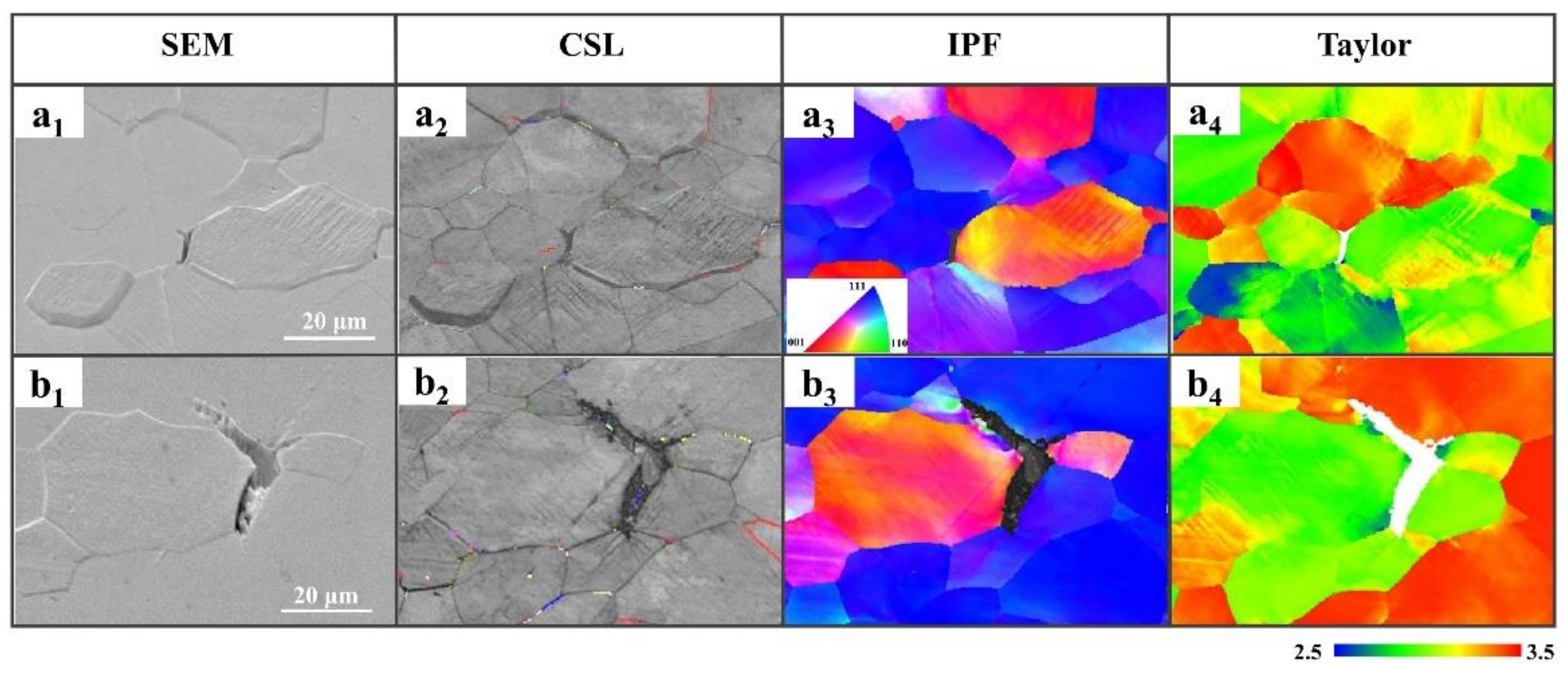
4.2. The Effect of Taylor Factor on Crack Propagation

The Taylor factor is used to analyze the level of plastic deformation, indicating the correlation between yield stress and crystal orientation in the metal. Grains with a lower Taylor factor are considered to have suitable orientations for slip, while a higher Taylor factor is associated with difficulty in plastic deformation occurrence. Grains with a high Taylor factor tend to be yield-resistant; therefore, transgranular cracks are expected [59].
Different Taylor factors between neighboring grains cause intergranular cracking at this location due to inconsistency [16]. Some grains that are already aligned in the loading direction can easily slip and deform. These grains have a low Taylor factor value [16], as shown in Figure 8(a4,b4). The ICs between {100} || ND and {111} || ND propagated due to the difference in the active slip system between neighboring grains, which results in the mismatch of Taylor factors. In other words, ICs occur along the crack propagation path between neighboring grains determined by mismatches between different Taylor factors. Although it can be seen from the figure that the Taylor factor is approximate on both sides of the crack, it is because the samples have been subjected to tensile deformation, resulting in an approximate angle with respect to tensile stress.

5. Conclusions

In this work, the influence of grain orientation on HE susceptibility of IF steels after the SSRT test was investigated by SEM, EBSD, and HMT analyses. The primary findings of this study are summarized as follows:
(1)
IF steels showed obvious HE susceptibility after the SSRT test with hydrogen charging, and their decrease in the reduction in area reached 70% (Iψ), which may severely damage the materials’ deep drawing performance and uniform deformation capacity in applications.
(2)
Hydrogen diffusion and segregation in IF steel were dependent on the crystal orientation. Hydrogen preferentially agglomerated around {100} || ND-oriented grains in ferrite grains under the condition of a high concentration of diffusible hydrogen, which makes the {100} || ND brittle. Grains with a {100} || ND orientation were susceptible to hydrogen and easily cracked along the GBs, while grains with a {111} || ND orientation were insusceptible to hydrogen and resistant to cracking. The Σ3 GBs hindered crack propagation. {111} || ND-oriented grains with a high Taylor factor (>3) are difficult to deform and crack.
(3)
The misorientation of GBs at 50–60° angles in IF steels was prone to cracking in a hydrogen environment. This study confirms that HICs usually propagate along GBs with a large misorientation.
(4)
For the purpose of textural design, the best resistance against crack propagation results in minimizing the {100} plane || ND and increasing the desirable {111} || ND fiber components that are close to the compact planes. The formation of strong covalent bonds between two lattices linked together by a close-packed plane leads to obstacles to crack propagation and increases HIC resistance. Although there are differences between the laboratory (rapid evaluation) and engineering applications (much longer service time), we still believe that it may be one of the effective methods to improve the HE resistance of IF steel by appropriate rolling and heat treatment processes to optimize the microstructure (microtexture and GB characteristics), such as reducing the {100} || ND micro-oriented texture.

Author Contributions

Conceptualization, W.W. and J.L.; methodology, W.W., H.F. and J.L.; software, H.Z.; formal analysis, Y.Y.; investigation, W.W.; writing—original draft preparation, W.W.; writing—review and editing, W.W., H.F. and J.L. All authors have read and agreed to the published version of the manuscript.

Funding

This research was funded by the National Nature Science Foundation of China, grant numbers 52071016 and U1964204.

Data Availability Statement

The raw/processed data required to reproduce these findings cannot be shared at this time due to being part of an ongoing project. Requests for the data may be made via written request via email, and data will be provided upon reasonable request when the project has concluded.

Conflicts of Interest

We declare that we have no financial or personal relationship with other people or organizations that inappropriately influenced our work. There is no professional or other personal interest of any nature or any product, service, or company that could be construed as influencing the position presented in or the review of this manuscript.

References

  1. Wang, Z.; Kan, B.; Xu, J.; Li, J. The effect of second tempering on hydrogen embrittlement of ultra-high-strength steel. Metall. Mater. Trans. A 2020, 51, 2811–2821. [Google Scholar] [CrossRef]
  2. Nagao, A.; Smith, C.D.; Dadfarnia, M.; Sofronis, P.; Robertson, I.M. Interpretation of hydrogen-induced fracture surface morphologies for lath martensitic steel. Procedia Mater. Sci. 2014, 3, 1700–1705. [Google Scholar] [CrossRef] [Green Version]
  3. Nagao, A.; Martin, M.L.; Dadfarnia, M.; Sofronis, P.; Robertson, I.M. The effect of nanosized (Ti,Mo)C precipitates on hydrogen embrittlement of tempered lath martensitic steel. Acta Mater. 2014, 74, 244–254. [Google Scholar] [CrossRef]
  4. Shi, R.; Chen, L.; Wang, Z.; Yang, X.S.; Qiao, L.; Pang, X. Quantitative investigation on deep hydrogen trapping in tempered martensitic steel. J. Alloys Compd. 2021, 854, 157218. [Google Scholar] [CrossRef]
  5. Silverstein, R.; Eliezer, D. Mechanisms of hydrogen trapping in austenitic, duplex, and super martensitic stainless steels. J. Alloys Compd. 2017, 720, 451–459. [Google Scholar] [CrossRef]
  6. Nagao, A.; Smith, C.D.; Dadfarnia, M.; Sofronis, P.; Robertson, I.M. The role of hydrogen in hydrogen embrittlement fracture of lath martensitic steel. Acta Mater. 2012, 60, 5182–5189. [Google Scholar] [CrossRef]
  7. Momotani, Y.; Shibata, A.; Terada, D.; Tsuji, N. Hydrogen embrittlement behavior at different strain rates in low-carbon martensitic steel. Mater. Today Proc. 2015, 2, S735–S738. [Google Scholar] [CrossRef]
  8. Momotani, Y.; Shibata, A.; Terada, D.; Tsuji, N. Effect of strain rate on hydrogen embrittlement in low-carbon martensitic steel. Int. J. Hydrog. Energy 2017, 42, 3371–3379. [Google Scholar] [CrossRef]
  9. Zhu, X.; Li, W.; Zhao, H.; Wang, L.; Jin, X. Hydrogen trapping sites and hydrogen-induced cracking in high strength quenching & partitioning (Q&P) treated steel. Int. J. Hydrog. Energy 2014, 39, 13031–13040. [Google Scholar]
  10. Liu, P.W.; Wu, J.K. Hydrogen susceptibility of an interstitial free steel. Mater. Lett. 2003, 57, 1224–1228. [Google Scholar] [CrossRef]
  11. Wasim, M.; Djukic, M.B. Hydrogen embrittlement of low carbon structural steel at macro-, micro-and nano-levels. Int. J. Hydrog. Energy 2020, 45, 2145–2156. [Google Scholar] [CrossRef]
  12. Djukic, M.B.; Zeravcic, V.S.; Bakic, G.; Sedmak, A.; Rajicic, B. Hydrogen embrittlement of low carbon structural steel. Procedia Mater. Sci. 2014, 3, 1167–1172. [Google Scholar] [CrossRef] [Green Version]
  13. Lynch, S. Hydrogen embrittlement phenomena and mechanisms. Corros. Rev. 2012, 30, 105–123. [Google Scholar] [CrossRef]
  14. Fu, H.; Wang, W.; Chen, X.; Pia, G.; Li, J. Fractal and multifractal analysis of fracture surfaces caused by hydrogen embrittlement in high-Mn twinning/transformation-induced plasticity steels. Appl. Surf. Sci. 2019, 470, 870–881. [Google Scholar] [CrossRef]
  15. Łabanowski, J.; Świerczyńska, A.; Topolska, S. Effect of microstructure on mechanical properties and corrosion resistance of 2205 duplex stainless steel. Pol. Marit. Res. 2014, 4, 108–112. [Google Scholar] [CrossRef] [Green Version]
  16. Masoumi, M.; Silva, C.C.; de Abreu, H.F.G. Effect of crystallographic orientations on the hydrogen-induced cracking resistance improvement of API 5L X70 pipeline steel under various thermomechanical processing. Corros. Sci. 2016, 111, 121–131. [Google Scholar] [CrossRef]
  17. Masoumi, M.; Tavares, S.S.M.; Pardal, J.M.; Martins, T.R.B.; da Silva, M.J.G.; de Abreu, H.F.G. The role of microstructure and grain orientations on intergranular cracking susceptibility of UNS 17400 martensitic stainless steel. Eng. Fail. Anal. 2017, 79, 198–207. [Google Scholar] [CrossRef]
  18. Masoumi, M.; Santos, L.P.M.; Bastos, I.N.; Tavares, S.S.; da Silva, M.J.; de Abreu, H.F.G. Texture and grain boundary study in high strength Fe–18Ni–Co steel related to hydrogen embrittlement. Mater. Des. 2016, 91, 90–97. [Google Scholar] [CrossRef]
  19. Masoumi, M.; Coelho, H.L.F.; Tavares, S.S.M.; Silva, C.C.; De Abreu, H.F.G. Effect of grain orientation and boundary distributions on hydrogen-induced cracking in low-carbon-content steels. Jom 2017, 69, 1368–1374. [Google Scholar] [CrossRef]
  20. Masoumi, M.; Silva, C.C.; Béreš, M.; Ladino, D.H.; de Abreu, H.F.G. Role of crystallographic texture on the improvement of hydrogen-induced crack resistance in API 5L X70 pipeline steel. Int. J. Hydrog. Energy 2017, 42, 1318–1326. [Google Scholar] [CrossRef]
  21. Masoumi, M.; Herculano, L.F.G.; de Abreu, H.F.G. Study of texture and microstructure evaluation of steel API 5L X70 under various thermomechanical cycles. Mater. Sci. Eng. A 2015, 639, 550–558. [Google Scholar] [CrossRef]
  22. Masoumi, M.; Ariza, E.A.; Sinatora, A.; Goldenstein, H. Role of crystallographic orientation and grain boundaries in fatigue crack propagation in used pearlitic rail steel. Mater. Sci. Eng. A 2018, 722, 147–155. [Google Scholar] [CrossRef]
  23. Venegas, V.; Caleyo, F.; Baudin, T.; Espina-Hernandez, J.H.; Hallen, J.M. On the role of crystallographic texture in mitigating hydrogen-induced cracking in pipeline steels. Corros. Sci. 2011, 53, 4204–4212. [Google Scholar] [CrossRef]
  24. Venegas, V.; Caleyo, F.; Baudin, T.; Hallen, J.M.; Penelle, R. Role of microtexture in the interaction and coalescence of hydrogen-induced cracks. Corros. Sci. 2009, 51, 1140–1145. [Google Scholar] [CrossRef]
  25. Ghosh, A.; Kundu, S.; Chakrabarti, D. Effect of crystallographic texture on the cleavage fracture mechanism and effective grain size of ferritic steel. Scr. Mater. 2014, 81, 8–11. [Google Scholar] [CrossRef]
  26. Schreiber, A.; Rosenkranz, C.; Lohrengel, M.M. Grain-dependent anodic dissolution of iron. Electrochim. Acta 2007, 52, 7738–7745. [Google Scholar] [CrossRef]
  27. Mohtadi-Bonab, M.A.; Eskandari, M.; Rahman, K.M.M.; Ouellet, R.; Szpunar, J.A. An extensive study of hydrogen-induced cracking susceptibility in an API X60 sour service pipeline steel. Int. J. Hydrog. Energy 2016, 41, 4185–4197. [Google Scholar] [CrossRef]
  28. Fu, H.; Wang, W.; Chen, X.; Pia, G.; Li, J. Grain boundary design based on fractal theory to improve intergranular corrosion resistance of TWIP steels. Mater. Des. 2020, 185, 108253. [Google Scholar] [CrossRef]
  29. Seita, M.; Hanson, J.P.; Gradečak, S.; Demkowicz, M.J. The dual role of coherent twin boundaries in hydrogen embrittlement. Nat. Commun. 2015, 6, 1–6. [Google Scholar] [CrossRef]
  30. Pérez, T.E.; García, J.O. Direct observation of hydrogen evolution in the electron microscope scale. Scr. Metall. 1982, 16, 161–164. [Google Scholar] [CrossRef]
  31. Ovejero-García, J. Hydrogen microprint technique in the study of hydrogen in steels. J. Mater. Sci. 1985, 20, 2623–2629. [Google Scholar] [CrossRef]
  32. Chen, S.S.; Wu, T.I.; Wu, J.K. Effects of deformation on hydrogen degradation in a duplex stainless steel. J. Mater. Sci. 2004, 39, 67–71. [Google Scholar] [CrossRef]
  33. Yalçì, H.K.; Edmonds, D.V. Application of the hydrogen microprint and the microautoradiography techniques to a duplex stainless steel. Mater. Charact. 1995, 34, 97–104. [Google Scholar] [CrossRef]
  34. Ronevich, J.A.; Speer, J.G.; Krauss, G.; Matlock, D.K. Improvement of the hydrogen microprint technique on AHSS steels. Metallogr. Microstruct. Anal. 2012, 1, 79–84. [Google Scholar] [CrossRef] [Green Version]
  35. Ohmisawa, T.; Uchiyama, S.; Nagumo, M. Detection of hydrogen trap distribution in steel using a microprint technique. J. Alloys Compd. 2003, 356, 290–294. [Google Scholar] [CrossRef]
  36. Allen, Q.S.; Nelson, T.W. Microstructural evaluation of hydrogen embrittlement and successive recovery in advanced high strength steel. J. Mater. Processing Technol. 2019, 265, 12–19. [Google Scholar] [CrossRef] [Green Version]
  37. Yoshioka, M.; Ueno, A.; Kishimoto, H. Analysis of hydrogen behaviour in crack growth tests of γ-TiAl by means of the hydrogen microprint technique. Intermetallics 2004, 12, 23–31. [Google Scholar] [CrossRef]
  38. Hayakawa, Y.; Szpunar, J.A. Modeling of texture development during recrystallization of interstitial free steel. Acta Mater. 1997, 45, 2425–2434. [Google Scholar] [CrossRef]
  39. Hutchinson, W.B. Recrystallisation textures in iron resulting from nucleation at grain boundaries. Acta Metall. 1989, 37, 1047–1056. [Google Scholar] [CrossRef]
  40. Hutchinson, W.B. Development and control of annealing textures in low-carbon steels. Int. Met. Rev. 1984, 29, 25–42. [Google Scholar] [CrossRef]
  41. Ray, R.K.; Jonas, J.J.; Hook, R.E. Cold rolling and annealing textures in low carbon and extra low carbon steels. Int. Mater. Rev. 1994, 39, 129–172. [Google Scholar] [CrossRef]
  42. Chen, L.; Ma, Z.; Shi, R.; Su, Y.; Qiao, L.; Wang, L. Comprehensive effect of hydrostatic compressive stress in retained austenite on mechanical properties and hydrogen embrittlement of martensitic steels. Int. J. Hydrog. Energy 2020, 45, 22102–22112. [Google Scholar] [CrossRef]
  43. Yang, J.; Huang, F.; Guo, Z.; Rong, Y.; Chen, N. Effect of retained austenite on the hydrogen embrittlement of a medium carbon quenching and partitioning steel with refined microstructure. Mater. Sci. Eng. A 2016, 665, 76–85. [Google Scholar] [CrossRef]
  44. Roe, R.J. Description of crystallite orientation in polycrystalline materials. III. General solution to pole figure inversion. J. Appl. Phys. 1965, 36, 2024–2031. [Google Scholar] [CrossRef]
  45. De Knijf, D.; Nguyen-Minh, T.; Petrov, R.H.; Kestens, L.A.I.; Jonas, J.J. Orientation dependence of the martensite transformation in a quenched and partitioned steel subjected to uniaxial tension. J. Appl. Crystallogr. 2014, 47, 1261–1266. [Google Scholar] [CrossRef]
  46. Rugg, D.; Dixon, M.; Dunne, F.P.E. Effective structural unit size in titanium alloys. J. Strain Anal. Eng. Des. 2007, 42, 269–279. [Google Scholar] [CrossRef]
  47. Tran, R.; Xu, Z.; Radhakrishnan, B.; Winston, D.; Sun, W.; Persson, K.A.; Ong, S.P. Surface energies of elemental crystals. Sci. Data 2016, 3, 1–13. [Google Scholar] [CrossRef] [Green Version]
  48. Xie, D.G.; Wang, Z.J.; Sun, J.; Li, J.; Ma, E.; Shan, Z.W. In situ study of the initiation of hydrogen bubbles at the aluminium metal/oxide interface. Nat. Mater. 2015, 14, 899–903. [Google Scholar] [CrossRef] [PubMed]
  49. Masoumi, M.; Sinatora, A.; Goldenstein, H. Role of microstructure and crystallographic orientation in fatigue crack failure analysis of a heavy haul railway rail. Eng. Fail. Anal. 2019, 96, 320–329. [Google Scholar] [CrossRef]
  50. Ilyin, A.M. Some features of grain boundary segregations in sensitized austenitic stainless steel. J. Nucl. Mater. 1998, 252, 168–170. [Google Scholar] [CrossRef]
  51. Viswanathan, U.K.; Dey, G.K.; Asundi, M.K. Precipitation hardening in 350 grade maraging steel. Metall. Trans. A 1993, 24, 2429–2442. [Google Scholar] [CrossRef]
  52. Wang, Y.Z.; Atkinson, J.D.; Akid, R.; Parkins, R.N. Crack interaction, coalescence and mixed mode fracture mechanics. Fatigue Fract. Eng. Mater. Struct. 1996, 19, 427–439. [Google Scholar] [CrossRef]
  53. Kan, B.; Wu, W.; Yang, Z.; Li, J. Stress-induced hydrogen redistribution and corresponding fracture behavior of Q960E steel at different hydrogen content. Mater. Sci. Eng. A 2020, 775, 138963. [Google Scholar] [CrossRef]
  54. Hayakawa, Y.; Szpunar, J.A. The role of grain boundary character distribution in secondary recrystallization of electrical steels. Acta Mater. 1997, 45, 1285–1295. [Google Scholar] [CrossRef]
  55. Dingreville, R.; Berbenni, S. On the interaction of solutes with grain boundaries. Acta Mater. 2016, 104, 237–249. [Google Scholar] [CrossRef] [Green Version]
  56. Mohtadi-Bonab, M.A.; Eskandari, M.; Sanayei, M.; Das, S. Microstructural aspects of intergranular and transgranular crack propagation in an API X65 steel pipeline related to fatigue failure. Eng. Fail. Anal. 2018, 94, 214–225. [Google Scholar] [CrossRef]
  57. Pradhan, S.K.; Bhuyan, P.; Mandal, S. Individual and synergistic influences of microstructural features on intergranular corrosion behavior in extra-low carbon type 304L austenitic stainless steel. Corros. Sci. 2018, 139, 319–332. [Google Scholar] [CrossRef]
  58. Kwon, Y.J.; Seo, H.J.; Kim, J.N.; Lee, C.S. Effect of grain boundary engineering on hydrogen embrittlement in Fe-Mn-C TWIP steel at various strain rates. Corros. Sci. 2018, 142, 213–221. [Google Scholar] [CrossRef]
  59. Roach, M.D.; Wright, S.I.; Lemons, J.E.; Zardiackas, L.D. An EBSD based comparison of the fatigue crack initiation mechanisms of nickel and nitrogen-stabilized cold-worked austenitic stainless steels. Mater. Sci. Eng. A 2013, 586, 382–391. [Google Scholar] [CrossRef]
Figure 1. Schematic diagram of single-side hydrogen charging in the HMT process.
Metals 12 00981 g001
Figure 2. Macro- and microtexture of as-received IF steel, (a) φ2 = 45° ODF section from the X-ray diffraction; (b) IPF from EBSD.
Metals 12 00981 g002
Figure 3. Stress-strain curves of hydrogen-uncharged and hydrogen-charged specimens at a 1 × 10⁻⁶ s−1 strain rate.
Metals 12 00981 g003
Figure 4. Fractographs of hydrogen-uncharged (a1a3) and hydrogen-charged specimens (b1b3): (a1) the overall morphology; (a2) the yellow box area in a1, low magnification; (a3) the local magnified image of the yellow box in (a2); (b1) the overall morphology; (b2) the red box area in (b1), low magnification; (b3) the local magnified image of the red box in (b2), red arrows represent intergranular crack (IC) and quasi-cleavage area.
Metals 12 00981 g004
Figure 5. Crack morphology of the specimens on the surface of RD-TD; (a) hydrogen-uncharged and (b) hydrogen-charged; (c) IPF map of hydrogen-charged specimen (12 random fields), in which the numbers represent IC misorientations.
Metals 12 00981 g005
Figure 6. Population of GB types of original IF steel.
Metals 12 00981 g006
Figure 7. Ratio of the crack orientation difference in the hydrogen-charged specimens.
Metals 12 00981 g007
Figure 8. Two different fields of hydrogen-charged specimen: SEM microstructure (a1,b1) and EBSD map (a2a4,b2b4) analysis of the cracks on the surface of RD-TD; (a2,b2) CSL maps, where the red line is Σ3 GB; (a3,b3) IPF maps; (a4,b4) Taylor maps.
Metals 12 00981 g008
Figure 9. In situ HMT analysis of SEM and EBSD before (a,b) and after (c,d) hydrogen charging of the specimen; the white dotted box in (a) corresponds to (b,c); the numbers in (b) represent the misorientations of the GBs; the bottom-left in (c) is a locally magnified area; (d) surface distribution of Ag.
Metals 12 00981 g009
Table 1. Chemical composition of the investigated steel.
ComponentCMnSPSiNAlTiFe
Content wt%0.00670.0120.00830.00860.00830.00360.0200.066Bal.
Table 2. The percentage of low-index orientations.
Orientation{100}{110}{111}Other
Percentage (%)4.732.9378.7013.64
Table 3. The relationship between the number of hydrogen-induced microcracks and the grain orientation.
Orientation{100}{110}{111}Other
Average no. of grains1661032762479
No. of intergranular cracks162508
No. of cracks per 103 grains96.419.418.116.7
Publisher’s Note: MDPI stays neutral with regard to jurisdictional claims in published maps and institutional affiliations.

