1. Introduction
Cross-wire welding (CWW) is one of the spot resistance welding (SRW) [
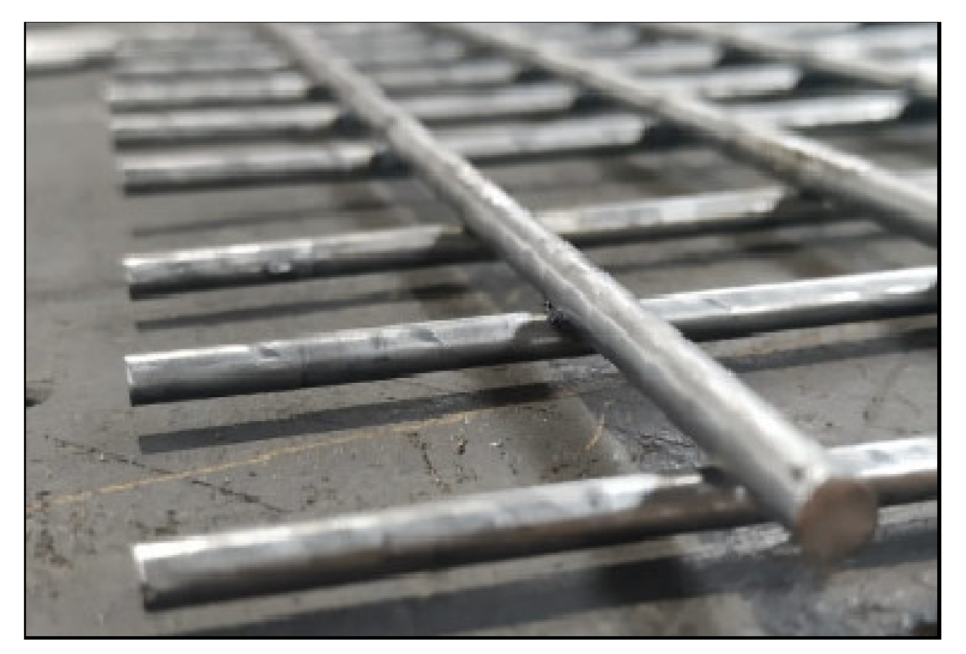
1] methods and refers to the joining of two wires of different diameters that are perpendicular to each other [
2]. The subject of research within the project “European regional development fund project” is a welded joint between two wires of a certain diameter (
Figure 1). The amount of penetration of one wire into another one depends on the set welding parameters, and it is one of the quality indicators of the resulting joint. An indispensable part of the SRW production process is the quality control of obtained joint [
3]. Due to the specific shape of the controlled product, this paper describes one of the non-contact measurement control procedures of wire-to-wire penetration at the joint, which is a base for further analysis of quality control of the obtained joint. Once the first phase of control is satisfied, and it is confirmed that a certain percentage of penetration has been achieved, controlled weld joint proceeds to further control procedures to check appearance of weld, strength and at last corrosion resistance as final advantage of joined materials. Over the last decades, there have been improvement in joining materials technology and anticorrosion behaviour [
4,
5,
6,
7]. The research conducted and documented in this paper provides a scientific contribution to the development and application of reconfigurable measuring systems (RMS) in testing of specifically shaped welded joint characteristics in industrial environment.
Reconfigurable systems were developed by scientists at the University of Michigan [
8], and up to today, more different prototypes of such devices have been developed [
9,
10,
11,
12]. Such systems are designed in accordance with certain principles and the more they are applied, the more reconfigurable a particular system is [
13]. Reconfigurability concept is gaining practical significance and has been strengthened by strong and considerable economic benefits [
14]. According to the purpose, there are several types of reconfigurable machines [
15], one of which is a product inspection machine such as [
16,
17,
18]. The emphasis of such control systems is on sensors and non-contact measurement of certain characteristics. The purpose of RMS is to enable sufficiently fast and complete product quality control in accordance with the required characteristics and capabilities.
According to the principles of reconfigurability, the definition of a reconfigurable measuring system would define it as a system designed in such a way that it can be quickly adjusted to control characteristics of a particular product group or within different groups. Based on the classification of features for selected product group, the preliminary model of the measuring system was analysed and the optimal one was selected. The prototype of the measuring system equipped with the necessary measuring sensors was constructed and built based on selected preliminary model of measuring system. It is made for one or more groups of products with specific characteristics. This approach is also environmentally friendly as limited use of resources (minimum amount) is one of the key guidelines. According to the concept of reconfigurability, it is necessary to meet certain requirements in order for the system to be called such. The architecture of the RMS construction must be modular, allowing modules (de)installation to (from) the system. In order to adapt the RMS to a new product from the same product group, the locations of individual modules can be reconfigured. The main advantage of such a system is to promptly have feedback on the quality of each product during production process, and with the use of available technology within the smart factory concept, it is possible to immediately make adjustments to the production line if deemed necessary.
Two perpendicular wires welded by the CWW process represent one group of products that will be controlled on a specially designed RMS that can be adapted also for other product groups when needed. The group of products studied in this paper consists of two circular cross-section wires with a certain diameter. Based on characteristics of welded pieces other groups of products shall be also defined, e.g., steel strips and wires product group or steel strips and strips group, both with variations in items dimensions. When it is necessary to test a completely different product, new product groups will be established based on product characteristics.
The factory where items for analysis (
Figure 1) are produced is equipped with a robotic cell for the SRW/CWW process (
Figure 2), which enables and facilitates the monitoring and change of welding parameters.
2. Materials and Methods
Steel grade of wire material is S235 and this kind of material is widely used in everyday life and can be found in the form of grids, gratings, fencing systems, baskets, etc.
It is desirable that quality control systems are accurate and versatile enough to allow measurement of produced parts and to prove more information related to performed measurements at the same time. The designed RMS uses machine vision to obtain the necessary measurements with the help of photogrammetry [
19,
20]. The camera has found an important place in product quality control as part of industrial photogrammetry, industrial metrology and the industry 4.0 concept in general.
Today’s industrial production without machine vision is unthinkable, and can be found in all types of industry, production and within product quality control, subsequently, it is increasingly represented in the application of welding and welding control.
Simple optical mechanisms allow a wide range of optical methods that allow the measurement of various objects regardless of size. Optical measurement systems can be divided according to [
21].
The price of components and software is a limiting factor in the field of vision control. Many manufacturing systems do not have the resources to implement quality vision systems as part of full product control, but can only afford low-budget devices [
22].
Processing of 2D obtained photos is mostly used for detection of objects and their parts, measuring dimensions and reading of symbols and text, etc.
According to the requirements for quality control and preliminary research, the method of control of individual dimensions of a given product was chosen, by non-contact measurement. With the development of non-contact measurement, much more reconfigurability has been enabled by moving optical systems to areas of interest.
Machine vision technology includes image collection, image, and data processing while the machine vision system consists of hardware and software [
23]. The main components of hardware are the computer as an essential part, cameras with mounted corresponding lenses, light, stand, and cables. For this purpose, the sensor used for measurement is selected according to the measured subject dimensions and measurement requirements. As the measurement subject is of small dimensions and complex shape, the industrial camera was chosen together with the telecentric lens. The telecentric lens has proven to be the best choice for precise measurements of small dimensions and it has a constant magnification regardless of the object’s distance from the lens. For this reason, it is often used in metrology and vision systems that require high measurement accuracy. Telecentric lenses have a high resolution, low distortion, and stable magnification [
24]. For the purpose of illuminating subjects that are dark and reducing the unfavourable reflection (because of the material of wire—steel S235) that occurs, LED lighting is most often used as a light source. It shall be noted that it is important to pay attention to the appearance of shadows and the lifespan of a lighting system. LED lighting with direct front lighting provides a high contrast between the subject and the background [
25]. To avoid the appearance of shadows, the ring shape of LED lighting was used in combination with LED compact flat lighting.
Image processing software is required. Most cameras come with applications used to display images and configure the camera. In this research, Basler cameras with associated software for image acquisition were used. Special applications and specific image processing tasks require specialized software that can be purchased or developed. Development of specialized software can be a complex operation, so ”off the shelf” software is used more often. Solutions are already available for many standard imaging tasks, such as Halcon or LabView.
The used RMS consists of standard modules that are easily available, such as the listed optical devices, computers, light sources, software, accessories that perform certain operations specified by the program, etc. Used modules and their main characteristics are shown in
Table 1. Individual modules can be (de)installed to (from) at the required position depending on the product planned to be measured as shown in
Figure 3. Positions of a particular module depend on the characteristics of the product group that needs to be measured and inspected at this point. This configuration of RMS enables checking of multiple features at the same time, such as the dimension of each wire, dimension of wire to wire penetration, and visual inspection for further analyses. The main advantage of the presented RMS is that in order to adjust it to the other group product, the locations of the individual modules can be reconfigured in such a way that they will be placed in a position that will allow inspection of required characteristics for a new product, considering special calibration procedure.
2.1. Calibration Procedure
To assure that measuring equipment is reliable, it is necessary to do calibration procedure in regular intervals or once the need arises (due to some change in the system, etc.). In order to make calibration as simple and fast as possible, it is necessary to use a reference object, such as glass objects with incised markings, metal parts machined with specified dimensions, or metal sheets with precisely drilled holes [
26]. To complete the project task, it is necessary to determine the dimension of the wire in the wire penetration. The first step in determining the exact dimension obtained by the vision system is the RMS calibration procedure [
27]. This includes a process that sets a ratio (the conversion factor) between image pixel and real distance, which is required in order to scale the recorded image to metric units. Appropriate referenced object with familiar dimensions is used to set conversion ratio in order to relate size image pixels with recorded. The image is made of pixels. Each pixel contains a set of information and has an assigned location in the 2 axis coordinate system. Digital images have a certain number of pixels and through the process of image digitization, there is a loss of a certain amount of information, as the real image must be summarized to a certain number of pixels. After selecting the appropriate object, it is necessary to know the procedure of image recording and measurement [
26].
Calibration of the RMS system must be performed in the same conditions in which further measurements will be performed, and this includes the same camera settings, the same lighting, the same equipment, and the same environmental conditions.
It is best to calibrate equipment using an object that is similar in size and shape to the object for which such a system will be used. Due to their price, reference objects are more often one-dimensional plates with inscribed markings, but they can also be precisely produced 3D objects with regular and rectangular planes [
28]. In this study, calibration is performed by using a reference object whose geometry in 3D space is known with very good precision. There are also other techniques like in [
29]. The reference object according to its surface characteristics must not affect the accuracy of the results. The error of the reference object itself must be less than the possible error of the system so as not to affect the accuracy of the results. In this research reference object has been designed for this product group and for this RMS (
Figure 4). Advantage of this reference object is that it can be used for different product groups and different modules if there is a requirement for change. The goal is to have one reference object (or set of objects) that will be used to calibrate RMS and to avoid new recalibration of RMS due to changes in the system.
For testing of the measuring system accuracy and confirming of calibration process a 6mm measuring standard shown in
Figure 5. was used, respecting the same conditions.
During the calibration process, the most important thing is to accurately determine the actual edge of the object. The edges of objects can be defined as abrupt transitions in the grey scale. Many authors deal with the detection of the edge of objects in images and use different filters [
28,
29,
30]. It is also necessary to ensure that the equipment and the reference object stand stably and firmly. The circular bubble level with high sensibility was used for this purpose.
If the camera focus is not set properly the contrast in the image is not optimal and calibration and measurement errors are more likely to occur. Focus allows the sharpening of the image. Best focus can only be achieved if a camera is installed at a certain distance from the subject. The dependence of the object distance and the focal plane is shown by the authors [
31]. The lens must be precisely focused on the plane of measurement. In an industrial environment, the distance between the subject and the camera is generally fixed, so manual focus is used instead of automatic focus. Small changes in the distance must not affect the change in the mm/px ratio, and if this happens, a telecentric lens must be used as it is more resistant to changes in focus settings. The human eye can easily estimate if an image is well focused but cannot estimate if it is optimal for image processing [
32].
Before setting up the object to be controlled, the equipment must be set up correctly, depending on the conditions that must be met. Images must be of the best possible quality to obtain the necessary information from the image. The camera resolution must be acceptable.
Component installation procedure:
Ensure that the colour of the background is in a contrast with the object
Ensure that the camera is perpendicular to the surface of the recorded subject
Ensure satisfactory lighting: shades of the object are not projected on the surface, no reflection, the object is properly illuminated to show necessary characteristics planned to be controlled, and there is sufficient contrast between the surface on which the object is located and the edge of the object once illuminated
If the image is taken at an angle, ensure that the used software can compensate for the error that occurs
Ensure proper system calibration before starting the measurement.
Author Contributions
Conceptualization, D.P. and M.V.; methodology, M.V.; writing—original draft preparation, D.I. and M.V.; software, M.V. and D.I.; validation, M.F.; writing—review and editing, M.V.; formal analysis and data curation, D.P.; investigation, M.V. and M.F. All authors have read and agreed to the published version of the manuscript.
Funding
This research was funded by the European structural and investment fund (ESIF) under the project number KK.01.2.1.02.0039 and the University of Rijeka (contract no. uniri-tehnic-18-33 and uniri-tehnic-18-223).
Institutional Review Board Statement
Not applicable.
Informed Consent Statement
Not applicable.
Data Availability Statement
Details regarding the data can be obtained by emailing the corresponding author.
Conflicts of Interest
The authors declare no conflict of interest. The funders had no role in the design of the study; in the collection, analyses, or interpretation of data; in the writing of the manuscript, or in the decision to publish the results.
References
- Iatcheva, I.; Darzhanova, D.; Manilova, M. Modeling of Electric and Heat Processes in Spot Resistance Welding of Cross-Wire Steel Bars. Open Phys. 2018, 16, 1–8. [Google Scholar] [CrossRef]
- Nielsen, C.V.; Zhang, W.; Bay, N.; Martins, P.A.F. Cross-Wire Welding Analyzed by Experiments and Simulations. J. Adv. Join. Process. 2021, 3, 100039. [Google Scholar] [CrossRef]
- Kim, S.; Hwang, I.; Kim, D.Y.; Kim, Y.M.; Kang, M.; Yu, J. Weld-Quality Prediction Algorithm Based on Multiple Models Using Process Signals in Resistance Spot Welding. Metals 2021, 11, 1459. [Google Scholar] [CrossRef]
- Jiang, H.; Liao, Y.; Gao, S.; Li, G.; Cui, J. Comparative Study on Joining Quality of Electromagnetic Driven Self-Piecing Riveting, Adhesive and Hybrid Joints for Al/Steel Structure. Thin-Walled Struct. 2021, 164, 107903. [Google Scholar] [CrossRef]
- Jiang, H.; Liao, Y.; Jing, L.; Gao, S.; Li, G.; Cui, J. Mechanical Properties and Corrosion Behavior of Galvanized Steel/Al Dissimilar Joints. Arch. Civ. Mech. Eng. 2021, 21, 168. [Google Scholar] [CrossRef]
- Dahmene, F.; Yaacoubi, S.; El Mountassir, M.; Bouzenad, A.E.; Rabaey, P.; Masmoudi, M.; Nennig, P.; Dupuy, T.; Benlatreche, Y.; Taram, A. On the Nondestructive Testing and Monitoring of Cracks in Resistance Spot Welds: Recent Gained Experience. Weld. World 2022, 66, 629–641. [Google Scholar] [CrossRef]
- Chabok, A.; Cao, H.; van der Aa, E.; Pei, Y. New Insights into the Fracture Behavior of Advanced High Strength Steel Resistance Spot Welds. J. Mater. Process. Technol. 2022, 301, 117433. [Google Scholar] [CrossRef]
- Koren, Y.; Heisel, U.; Jovane, F.; Moriwaki, T.; Pritschow, G.; Ulsoy, G.; Van Brussel, H. Reconfigurable Manufacturing Systems. CIRP Ann. Manuf. Technol. 1999, 48, 527–540. [Google Scholar] [CrossRef]
- Bi, Z.M.; Zhang, W.J. Flexible Fixture Design and Automation: Review, Issues and Future Directions. Int. J. Prod. Res. 2001, 39, 2867–2894. [Google Scholar] [CrossRef]
- Ho, J.K.L.; Ranky, P.G. Object Oriented Modelling and Design of Reconfigurable Conveyors in Flexible Assembly Systems Object Oriented Modelling and Design of Recon® Gurable Conveyors in ¯ Exible Assembly Systems. Int. J. Comput. Integr. Manuf. 1997, 10, 360–379. [Google Scholar] [CrossRef]
- Bi, Z.M.; Lang, S.Y.T.; Shen, W.; Wang, L. Reconfigurable Manufacturing Systems: The State of the Art. Int. J. Prod. Res. 2008, 46, 967–992. [Google Scholar] [CrossRef] [Green Version]
- Chen, I.M. Theory and Applications of Modular Reconfigurable Robotic Systems. Ph.D. Thesis, California Institute of Technology, Pasadena, CA, USA, 1994. [Google Scholar]
- Dashchenko, A.I. Reconfigurable Manufacturing Systems and Transformable Factories; Springer: Berlin/Heidelberg, Germany, 2006. [Google Scholar] [CrossRef]
- Singh, A.; Gupta, S.; Asjad, M.; Gupta, P. Reconfigurable Manufacturing Systems: Journey and the Road Ahead. Int. J. Syst. Assur. Eng. Manag. 2017, 8, 1849–1857. [Google Scholar] [CrossRef]
- Koren, Y. The Global Manufacturing Revolution: Product-Process-Business Integration and Reconfigurable Systems; John Wiley and Sons: Hoboken, NJ, USA, 2010. [Google Scholar]
- Xing, B.; Eganza, J.; Bright, G.; Potgieter, J. Reconfigurable Manufacturing System for Agile Manufacturing. IFAC Proc. Vol. 2006, 12 Pt 1, 509–516. [Google Scholar] [CrossRef]
- Bright, G.; Davrajh, S. Automated Apparatus for In-Line Inspection of Mass Produced Custom Parts. In Proceedings of the 2007 Australasian Conference on Robotics and Automation, ACRA 2007, Brisbane, Australia, 10–12 December 2007. [Google Scholar]
- Davrajh, S.; Bright, G. An Automated Apparatus for Dynamic Inspection of Mass-Produced Custom Parts. Assem. Autom. 2010, 30, 47–55. [Google Scholar] [CrossRef]
- Bösemann, W. Industrial Photogrammetry—Accepted Metrology Tool or Exotic Niche. Int. Arch. Photogramm. Remote Sens. Spat. Inf. Sci. ISPRS Arch. 2016, 41, 15–24. [Google Scholar] [CrossRef] [Green Version]
- Karsznia, K. Photogrammetric Precise Surveying Based on the Adjusted 3D Control Linear Network Deployed on a Measured Object. Appl. Sci. 2022, 12, 4571. [Google Scholar] [CrossRef]
- Steger, C.; Ulrich, M.; Wiedemann, C. Machine Vision Algorithms and Applications, 2nd ed.; John Wiley & Sons: Weinheim, Germany, 2018. [Google Scholar]
- Santosi, Z.; Budak, I.; Sokac, M.; Hadzistevic, M.; Vukelic, D. Influence of High Dynamic Range Images on the Accuracy of the Photogrammetric 3D Digitization: A Case Study. Adv. Prod. Eng. Manag. 2019, 14, 391–399. [Google Scholar] [CrossRef] [Green Version]
- Xiao, G.; Li, Y.; Xia, Q.; Cheng, X.; Chen, W. Research on the On-Line Dimensional Accuracy Measurement Method of Conical Spun Workpieces Based on Machine Vision Technology. Meas. J. Int. Meas. Confed. 2019, 148, 106881. [Google Scholar] [CrossRef]
- Li, W.; Wu, J.; Li, D.; Tian, Y.; Tian, J. Telecentricity Based Measurement Error Compensation in the Bilateral Telecentric System. Meas. J. Int. Meas. Confed. 2019, 147, 106822. [Google Scholar] [CrossRef]
- Huang, Y.; McMurran, R.; Dhadyalla, G.; Jones, R.P.; Mouzakitis, A. Model-Based Testing of a Vehicle Instrument Cluster for Design Validation Using Machine Vision. Meas. Sci. Technol. 2009, 20, 065502. [Google Scholar] [CrossRef]
- Demant, C.; Streicher-Abel, B.; Garnica, C. Industrial Image Processing, 2nd ed.; Springer: Berlin/Heidelberg, Germany, 2013. [Google Scholar] [CrossRef]
- Runje, B. Teorija i Tehnika Mjerenja; FSB: Zagreb, Croatia, 2014. [Google Scholar]
- He, H.; Li, H.; Huang, Y.; Huang, J.; Li, P. A Novel Efficient Camera Calibration Approach Based on K-SVD Sparse Dictionary Learning. Meas. J. Int. Meas. Confed. 2020, 159, 107798. [Google Scholar] [CrossRef]
- Zhang, Z. Flexible Camera Calibration by Viewing a Plane from Unknown Orientations. In Proceedings of the 7th IEEE International Conference on Computer Vision, Kerkyra, Greece, 20–27 September 1999; Volume 1, pp. 666–673. [Google Scholar] [CrossRef]
- Ziou, D.; Tabbone, S. Edge Detection Techniques—An Overview. Pria 1998, 8, 537–559. [Google Scholar]
- Maini, R.; Aggarwal, H. Study and Comparison of Various Image Edge Detection Techniques. Int. J. Image Process. 2009, 3, 1–11. [Google Scholar]
- Shrivakshan, G.T. A Comparison of Various Edge Detection Techniques Used in Image Processing. Int. J. Comput. Sci. Issues 2012, 9, 269–276. [Google Scholar]
- National Instruments. NI Vision for LabVIEW User Manual. Available online: https://www.ni.com/pdf/manuals/371007b.pdf (accessed on 26 August 2021).
- Riandini, R.; Dewantoro, S.K.; Istoni, R. Measurement of Stain Area in Metal Surface with Particle Analysis. In Proceedings of the ICAITI 2019—2nd International Conference on Applied Information Technology and Innovation, Denpasar, Indonesia, 21–22 September 2019; pp. 116–121. [Google Scholar] [CrossRef]
| Publisher’s Note: MDPI stays neutral with regard to jurisdictional claims in published maps and institutional affiliations. |
© 2022 by the authors. Licensee MDPI, Basel, Switzerland. This article is an open access article distributed under the terms and conditions of the Creative Commons Attribution (CC BY) license (https://creativecommons.org/licenses/by/4.0/).


