Article

Effect of Cooling Mode on the Microstructure of High-Strength Steel during Hot Rolling

1
Technology Research Institute of Bengang Steel Plates Co., Ltd., Benxi 117000, China
2
School of Metallurgy, Northeastern University, Shenyang 110004, China
3
CITIC Metal Co., Ltd., Beijing 100004, China
*
Author to whom correspondence should be addressed.
Metals 2022, 12(7), 1219; https://doi.org/10.3390/met12071219
Submission received: 22 June 2022 / Revised: 11 July 2022 / Accepted: 15 July 2022 / Published: 19 July 2022

Abstract

:
This paper studies the effect of extreme cooling and traditional cooling on the microstructure of high-strength steel during hot rolling by adjusting the cooling process, combining the theoretical calculation and the thermal simulation experiment, and using metallographic microscope, scanning electron microscope (SEM), and electron backscattered diffraction (EBSD) analysis methods in order to solve the problem of coil collapse in the production process of high-strength steel. The research results show that compared with the traditional cooling method, the front-section fast cooling mode can rapidly cool the hot-rolled sheet to the “nose tip” temperature of the ferrite transformation of the time-temperature-phase-transition (TTT) curve, which can promote the transformation of the material to ferrite, increase the proportion of ferrite, and make the grain size of the organization finer. It helps to improve the overall mechanical properties of the material and reduce coil collapse defects. The front-section fast cooling mode achieves good results in industrial application, the proportion of coil collapse reduces from 9.363% to 0.533%, and the problem of coil collapse is significantly improved.

1. Introduction

With the increasing pressure of energy saving and emission reduction in society, the development of high-strength steels is becoming more and more rapid. Hot-formed steels or cold-formed high-strength steels are used to replace low-strength products by reducing the thickness of materials to achieve weight reduction, energy saving, and emission reduction, which has become a common method for the production of “lightweight body-in-white” (BIW) in the automotive industry [1,2,3,4,5,6,7]. When designing the composition of high-strength steel, the carbon content is usually increased. Generally, the carbon content is between 0.1% and 0.3% during production combined with the rolling and heat treatment process. At the same time, Mn, Cr, Mo, and other alloys and microalloys, such as Nb, V, and Ti, are added. For some high-strength steels, B and other microalloys need to be added. Among them, the properties of hot-rolled and cold-rolled high-strength steel are highly dependent on the hot-rolled production process and microstructure, especially the cooling mode and coiling process system [8,9,10].
Generally, the segmented rolling process is adopted for hot rolling with a combination of controlled rolling and controlled cooling for production [11]. Among them, the control of coiling temperature is the core control technology [12,13]. In order to meet the production requirements of the pickling rolling process for hot-formed steel and cold-rolled high-strength steel products, the strength of the hot-rolled product should be controlled so that it is not too high. Therefore, a relatively high coiling temperature is adopted. However, if the phase transition is not fully completed before coiling, coil collapse will occur after coiling. Some coil collapse defects can be improved for some products by lowering the coiling temperature, but for some cold-rolled high-strength steel products, lowering the coiling temperature will result in excessive strength, which cannot meet the production requirements of pickling rolling.
How to ensure that the coil collapse does not occur under the higher coiling temperature is one of the core production technologies to guarantee the batch and stable production of high-strength steel [14]. According to some literature research [15,16,17], the effect of the cooling process on microstructure and phase transition is studied in this paper, and the way to reduce the coil collapse defect by improving the cooling mode is put forward and is applied in the practical production, which obtains a better effect. The research theory also has strong reference significance for improving other high-strength steel products.

2. Materials and Methods

2.1. Specimen Preparation

The typical composition of the high-strength steel selected in this test is shown in Table 1. The carbon content is 0.14%, and Cr, Mn, and a small amount of microalloying elements, such as Nb and Ti, are added. Some industrially produced high-strength steel was used for such test. After hot metal pretreatment, smelting in a converter, and secondary metallurgical treatment in a ladle furnace (LF, Danieli, Via Nazionale, Italy) and Rheinstahl–Heraeus (RH, SMS Demag, Siegen, Germany), the residual elements in the liquid steel were removed, and a slab was cut in a continuous casting process. The slab was heated to 1200 °C in a heating furnace and rolled by the thermomechanical control process (TMCP, NSC, Tokyo, Japan) in the hot-rolling process. The thickness of the slab was 210 mm. After rough rolling, the thickness of the intermediate slab was 35 mm. The sample was made before finishing the rolling and processed into a dumbbell shape with the size of the parallel test part of Φ 6 mm × 12 mm, which was used for the thermal simulation test.

2.2. Experimental Methods and Characterization Techniques

In this study, a Gleeble 2000 thermal analogue (DSI, St. Paul, MN, USA) was used for the continuous cooling test. Since the heating rate had no obvious effect on the microstructure of the experimental material, in order to improve the efficiency, the sample was heated to 1200 °C at 20 °C/s. According to our previous experimental experience [18], the soaking time was kept at 3 min for the sample to completely austenitized. After being cooled to 900 °C at a cooling rate of 20 °C/s and then subjected to unidirectional static compression simulation rolling with a 0.2 strain at a rate of 1 s−1, the sample cooled to 600 °C with two different cooling methods and then air-cooled to 200 °C to simulate the coiling process, as shown in Figure 1.
Sample 1, using the front-section fast cooling method in the front section, after straining, cooled to 650 °C at a cooling rate of 62 °C/s in simulated water-cooling mode, and then cooled to 600 °C at a cooling rate of 8 °C/s in simulated air-cooling mode.
Sample 2, using the traditional cooling method, first cooled to 870 °C at a cooling rate of 6 °C/s, and then cooled to 600 °C at a cooling rate of 54 °C/s.
The average cooling rate in two processes is the same, and the cooling process in the actual production between the finish rolling and the coiler is simulated, the residence time is 10 s, and the temperature is reduced from 900 to 600 °C for coiling, which means that the average cooling rate of the two methods is the same.
The central part of the thermal simulation sample was cut for microstructure analysis with a high-resolution optical microscope (Olympus BX51, Tokyo, Japan), electron backscattered diffraction (Bruker, Saarbrucken, Germany), and EVO 50 scanning electron microscope (Zeiss, Oberkochen, Germany) were used. The phase ratio was analyzed and tested by the IPP software (6.0, Media Cybernetics, Rockville, MD, USA).

3. Results

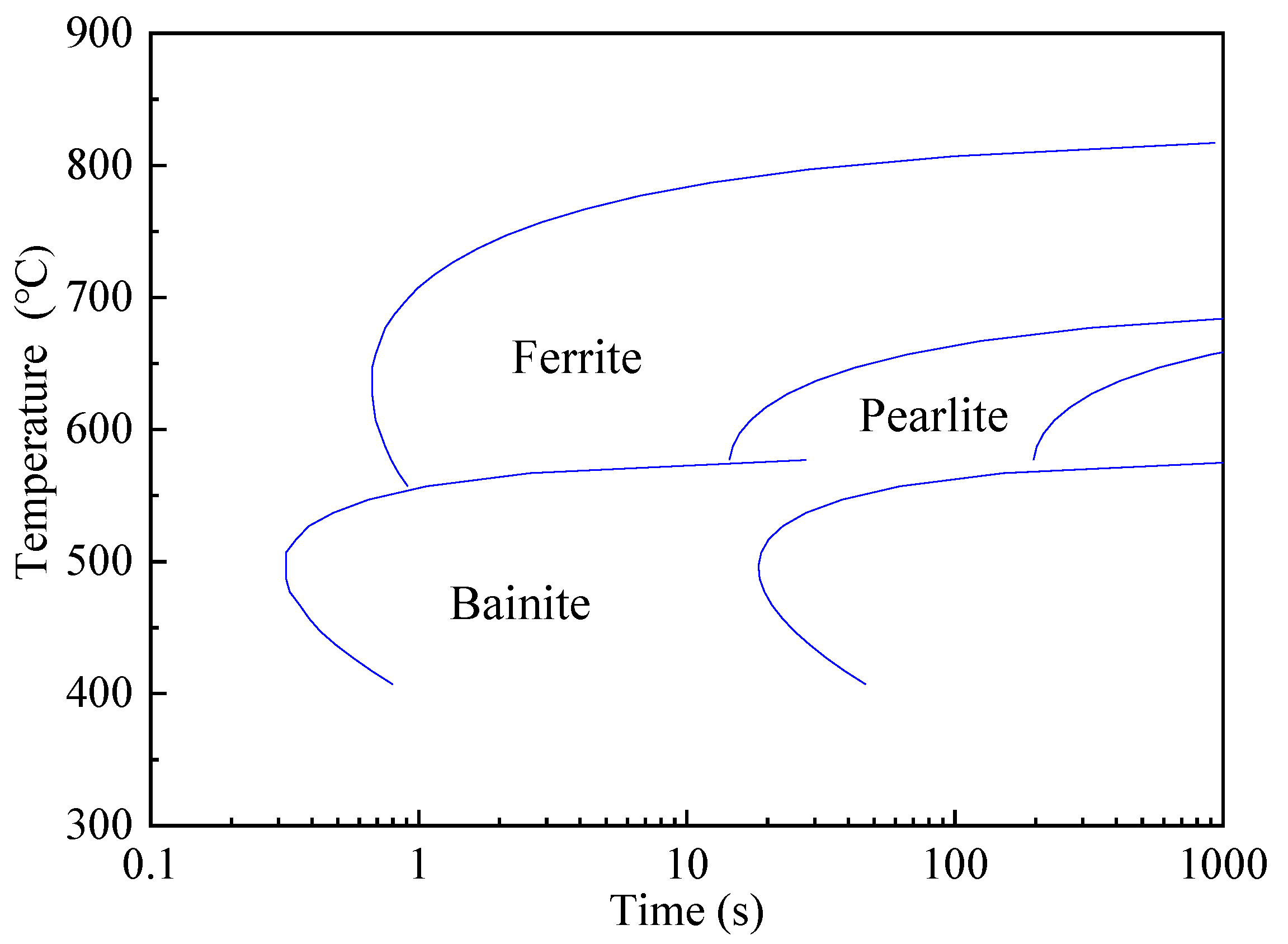
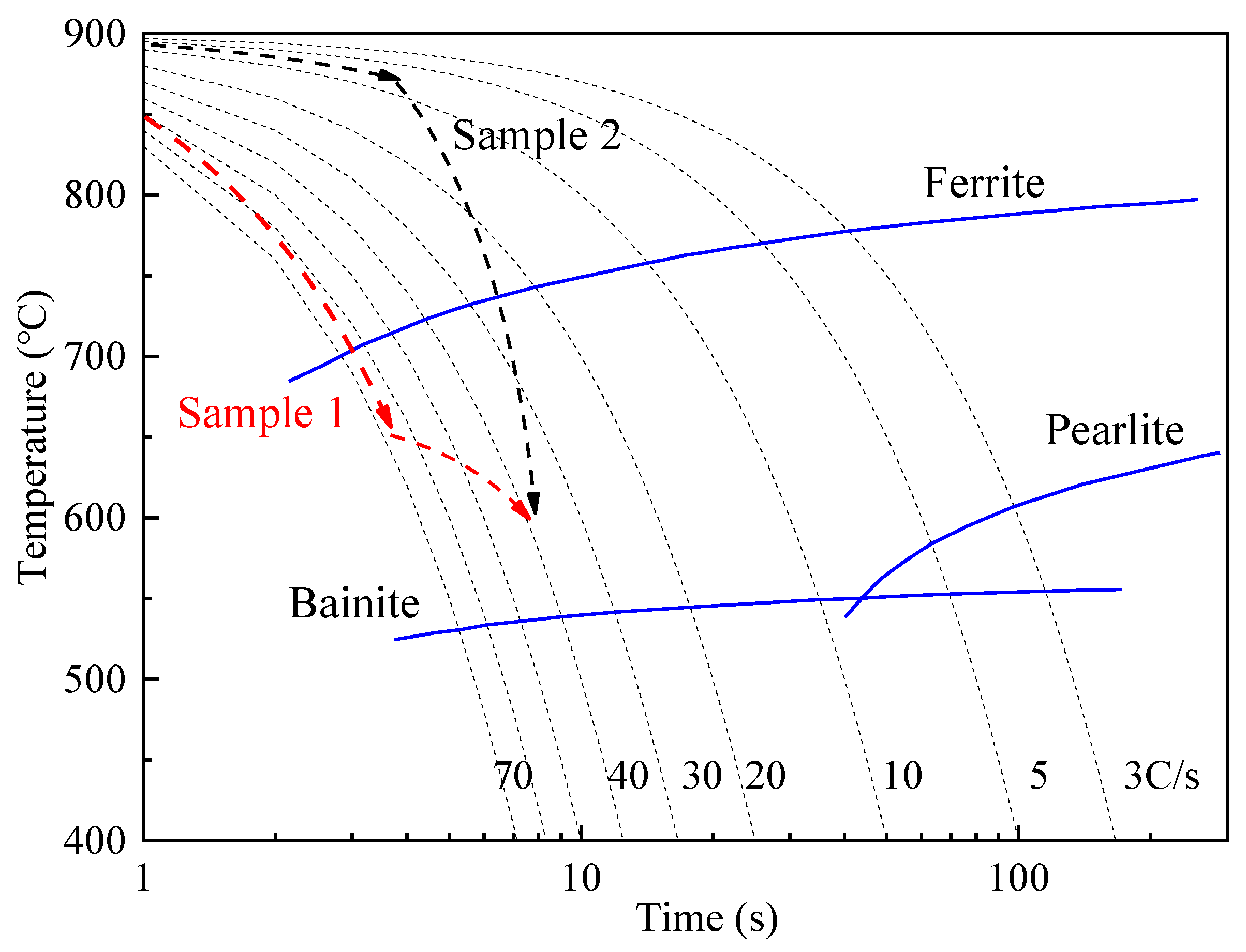
3.1. Phase Change Calculation for Different Cooling Processes

This section may be divided by subheadings. It provides a concise and precise description of the experimental results, their interpretation, and the experimental conclusions that can be drawn.
The thermodynamic calculation method was used to calculate the TTT curve of the components shown in Table 1, as shown in Figure 2. The results show that under equilibrium conditions, the transition nose tip temperature of ferrite is 637 °C, and the incubation time is 0.67 s. The higher is the temperature, the longer is the incubation time of ferrite transition. When the temperature decreases, the incubation time increases. After the temperature drops to 557 °C, bainite transition occurs.
The phase transition curve was calculated according to the process shown in Figure 1, as shown in Figure 3. Sample 1 started to cool at 900 °C, and then quickly cooled to 650 °C. Due to the fast cooling, less phase change occurred, but after the temperature reached 650 °C, the air-cooling time became relatively long. This temperature was close to the ferrite transition “nose tip” temperature, residual austenite rapidly transformed to ferrite, and the proportion of ferrite increased significantly. Ferrite completed 33.4% transition before coiling at 600 °C. During the subsequent cooling process, the structural stress of the hot-rolled coil was significantly reduced.
Sample 2 was cooled slowly at the beginning, and more ferrite transition occurred. However, due to the higher temperature, ferrite incubation time at 870 °C was too long, and the proportion of ferrite transition was less. Then the sample was cooled rapidly to 600 °C, the residence time in the fast ferrite transition region was shortened, and ferrite transition was insufficient. According to the calculation based on the phase diagram, the ferrite transition proportion at 600 °C was just 22.7%. After that, the transition of pearlite and bainite was completed. That is, 77.3% phase transition still occurred after coiling, and the structure stress was relatively large, which caused coil collapse [14].

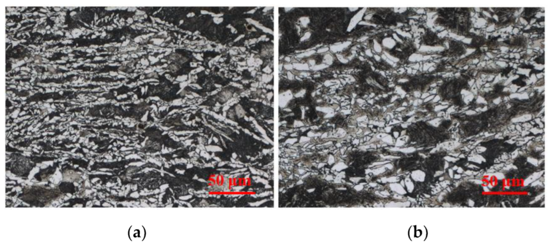
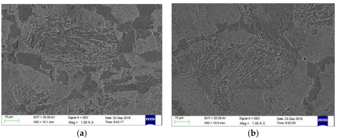
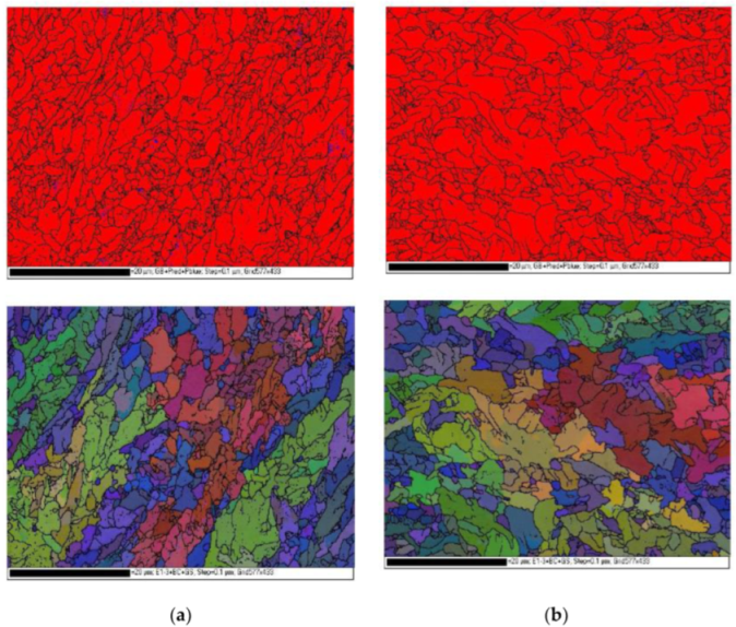
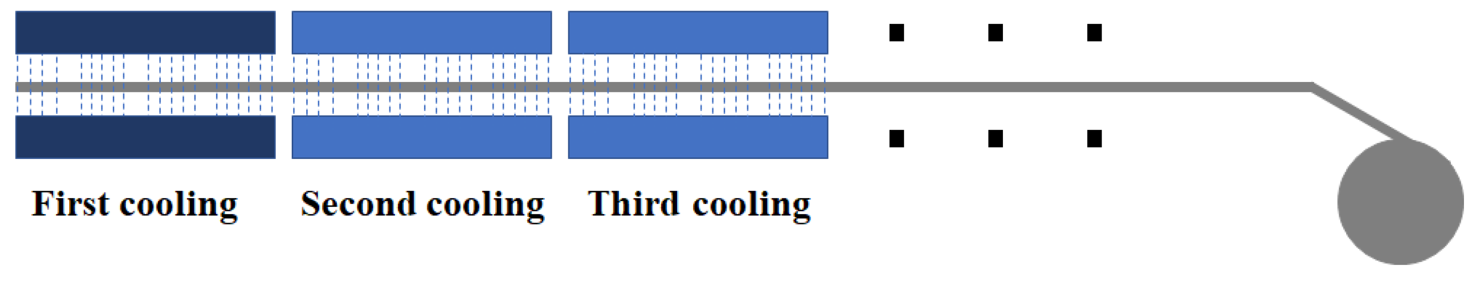
3.2. Simulation Structure of Different Cooling Processes

Using a Gleeble 2000 thermal analogue, the samples were simulated and tested in accordance with the process shown in Figure 1. For sample 1, the front-section fast cooling mode after rolling was simulated, and for sample 2, the backshift mode of cooling after rolling was simulated. Both samples were cooled from 900 to 600 °C within 10 s, and the average cooling rate was the same, which was also consistent with the production conditions on-site. The microstructure of the two samples is shown in Figure 4. Comparative analysis shows that the proportion of ferrite in sample 1 is significantly higher than that in sample 2. The ferrite of sample 1 has a significant proeutectoid morphology, the ferrite grain size is fine and a typical microstructure with a high degree of undercooling, and the tested ferrite ratio is 36.1%. The ferrite grain size of sample 2 is relatively coarse, the proportion of ferrite is slightly less and 29.6% after the test, the ratio of pearlite and bainite in the structure is slightly higher, and a martensite structure is found in some places.
The variation of ferrite proportion in industrial test results is consistent with that in the laboratory simulation results, but the grain size and the uniformity of the structure are quite different, which is related to the sample size during the actual industrial production and the time after coiling. The microstructure characteristics shown in Figure 4 are consistent with the theoretical calculation results shown in Figure 3, but the ferrite transition ratio is slightly higher than the theoretical calculation results, which is related to the strain and cooling rate in the actual simulation process through analysis. By theoretical calculation, it is in an equilibrium state, and the increase of strain in the thermal simulation test is beneficial to ferrite transition [18,19,20].

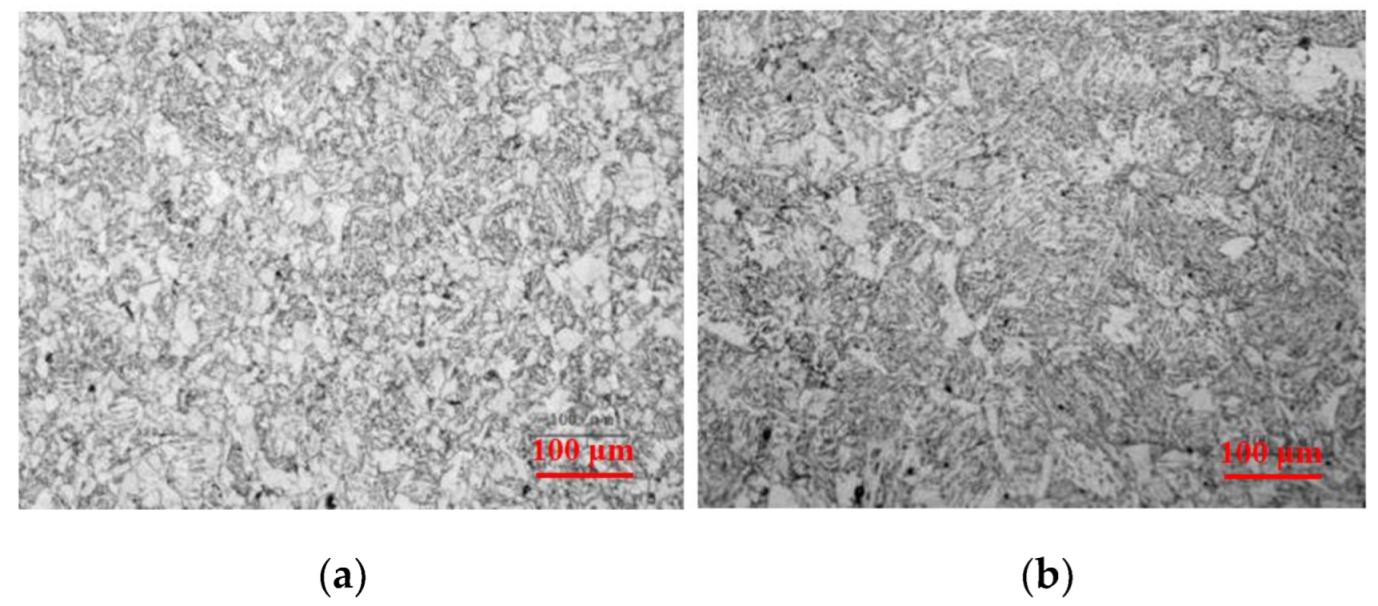
3.3. Comparison Results of the Industrial Production Test

In theory, more ferrite transition can be completed before phase transition by using the front-section cooling method, which is beneficial to improve the microstructure of cold-rolled high-strength steel and solve the problem of coil collapse. Two kinds of cooling methods were used for a comparative test on-site, and the microstructure of the hot-rolled sheet after cooling was observed, as shown in Figure 5. The proportion of ferrite in sample 1 is 24.9%, and that of sample 2 is 9.4%. It is found by comparison that the microstructure of the sample produced by the front-section fast cooling method has a higher proportion of ferrite. The result is consistent with the theoretical calculation result and similar to the simulation test result.
In order to further analyze the difference of structure transition with different cooling methods under industrial production conditions, the microstructure is analyzed by SEM in this study, as shown in Figure 6. It is found that ferrite transition is more sufficient with the front-section fast cooling method, as shown in Figure 6a; ferrite has the typical proeutectoid morphology; the interior of ferrite is relatively clean; and a complete continuous transition of ferrite occurs along the austenite grain boundary. Ferrite is adjacent to the typical pearlite structure and, finally, transforms to the internal bainite structure. The sample produced by the rear-section fast cooling method has a significant reduction in the proportion of ferrite and also presents the characteristics of intergranular proeutectoid transition, as shown in Figure 6b. However, the transition of ferrite is less, and the proportion of pearlite increases significantly.
In order to characterize the effect of the cooling process on the structure grain size, EBSD (Bruker, Saarbrucken, Germany) is used to analyze the effective grain size, as shown in Figure 7. The results show that the effective grain size obtained by the cooling method in process 1 has a remarkable refining effect, which is beneficial to improve the comprehensive properties of materials. This is more consistent with Abdullah’s [16] findings.
The ferrite proportion in industrial test results is consistent with that in the laboratory simulation results, but the grain size and the uniformity of the structure are quite different, which is related to the sample size during the actual industrial production and the holding time after coiling. After the test sample for hot simulation is cooled to 600 °C, a simulated coiling method at 1 °C/s is adopted to cool the sample to 200 °C. However, the sample is taken after coiling standing for 8 h in the actual industrial production, and there is a big difference in the cooling rate, which leads to a great difference in the structure. The variation of the structure in the simulation test is similar to that in the actual industrial production. The proportion of ferrite is increased, and the grain size is reduced by using the front-section fast cooling method.

4. Discussion

Coil collapse is a kind of production defect caused by the dimensional change of a hot-rolled coil. Microstructure stress and thermal stress after coiling cause such dimensional change because of the thinner thickness of the hot-rolled coil. It mainly occurs in the production of cold-rolled high-strength steel raw materials. According to the statistics of Ben Gang, cold-rolling raw materials above 780 MPa were produced continuously in the first quarter, and the proportion of coil collapse was 9.363%. According to the statistics of the annual production, the proportion in winter decreased and in summer increased.
As we all know, austenite has a face-centered cubic (FCC) crystal structure, and ferrite has a body-centered cube (BCC) crystal structure. The phase transition from an FCC structure to a BCC structure is a volume expansion process. The measurement of the phase transition temperature is also based on the characteristics of the volume expansion during the phase transition. If the phase transition is not completed before coiling during the industrial production of hot-rolled products, the phase transition will occur after coiling (i.e., volume expansion) [21]. After coiling, the temperature of the hot-rolled coil gradually decreases. Due to the effect of the thermal expansion and cold contraction, the volume shrinkage of the hot-rolled coil changes, and the difference causes coil collapse. Therefore, the key to solving the coil collapse defect is to complete the phase transition as much as possible before coiling and to control the amount of ferrite transition combined with TTT analysis.
In the process of industrial production, the distance between the finishing mill and the coiler is fixed. Normal production usually takes about 10 s. When the finishing rolling temperature and coiling temperature are fixed, the average cooling rate is fixed, and the phase transition is completed within 10 s. During coiling, more retained austenite leads to an increase in the proportion of phase transformation in the subsequent process, so the expansion caused by the structural transformation also increases, which leads to the phenomenon of coil collapse. Reducing the proportion of retained austenite during coiling can effectively solve the problem of coil collapse. In other words, a higher fraction of ferrite transformation during cooling is beneficial to the improvement of coil collapse. In order to meet different production control requirements, the cooling equipment of the hot tandem mill is generally divided into several sections, as shown in Figure 8. Usually, strip steel in the first section has the highest temperature and the strongest cooling capacity, which is used to produce pipeline steel and other products [22,23,24]. When producing cold-rolled products, a uniform cooling method is used to control the shape. Conventional production avoids the first-section cooling and starts with the second-section cooling (i.e., the process 2 method described in this research).
As shown in Figure 9, the continuous cooling transformation (CCT) curve is calculated for the sample, and the phase transition process of samples 1 and 2 is shown too. According to the TTT curve shown in Figure 2, the “nose tip” temperature of ferrite transition of the sample in this study is 637 °C, and the incubation time is only 0.67 s. When considering that the increase in strain is beneficial to ferrite transition, the ferrite transition temperature in the actual production is slightly higher than the theoretical calculation temperature. Therefore, the sample was cooled quickly to this temperature range and kept there; high undercooling is conducive to ferrite nucleation, as shown in Figure 10. At the austenite interface, ferrite nucleates rapidly, and the ferrite grain size is fine [25]. As mentioned in process 1 in this research, fast cooling is selected to be 650 °C, and the results of simulation and industrial tests show that the ferrite structure is relatively small and the ferrite transition is more sufficient. Compared with process 2, when entering the ferrite transition region at a relatively high temperature, the thermodynamic conditions are sufficient, but the dynamic conditions are insufficient. The undercooling degree is small, and the ferrite transition occurs only a few seconds before coiling, as shown in Figure 10. Therefore, ferrite still nucleates and grows at the austenite interface, but the nucleation rate decreases, the ferrite transition is relatively insufficient, and the proportion of ferrite in the final structure is relatively reduced. As shown in sample 2 in Figure 9, the amount of ferrite transition before final coiling in process 2 is significantly less than that in process 1. The simulation test results, theoretical calculation results, and field test results all verify this rule.
However, if the temperature of the first-section fast cooling is further reduced, which is lower than the “nose tip” temperature of the ferrite transition, it is unfavorable to ferrite transition. The coiling temperature is controlled at ±30 °C in the practical production. If the temperature is lower than 557 °C, bainite transition will occur and the material strength will increase rapidly [17,26], which is unfavorable to the subsequent pickling and rolling. Therefore, the first-section cooling can be controlled between 650 and 590 °C during the actual production according to the different compositions.
Combined with the basic data of this research and according to different components, the cooling methods for 780 MPa and above-level products were improved, and the coiling temperature was adjusted appropriately, and finally, the coil collapse problem was solved. At present, the coil collapse problem has been greatly improved in the production of 780 MPa products. According to the statistics of products in three consecutive months, some products with limited thin specifications were found with coil collapse, and the coil collapse proportion decreased from 9.363% to 0.533%.

5. Conclusions

  • According to the theoretical calculation and compared with the traditional cooling method, the front-section fast cooling mode increased the phase transformation ratio of the test steel from 22.7% to 33.4% before coiling, and the microstructure stress of the hot-rolled coil after coiling was significantly reduced, which improved the coil collapse problem.
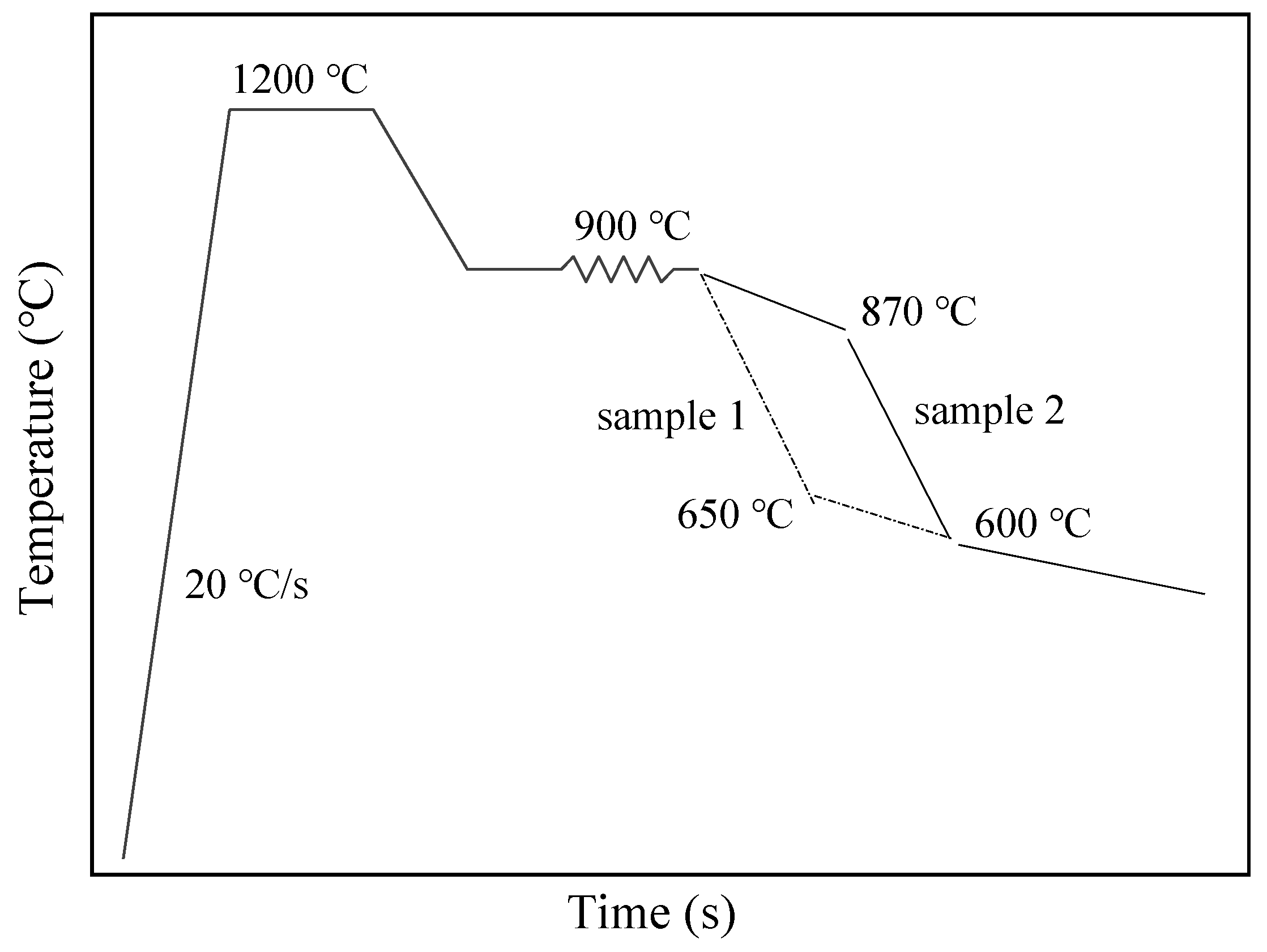
  • Through the thermal simulation experiments, the samples used the front-section fast cooling mode and could be cooled to the “nose tip” temperature of ferrite as soon as possible, which significantly increases the proportion of ferrite in the structure before coiling, and the grain size of the organization is finer. This is beneficial to the reduction of the microstructure stress during the cooling process of the hot-rolled coil after coiling.
  • There is good similarity between the industrial production and the thermal simulation experiment. According to the statistics of industrial products, it is found that the proportion of coil collapse of high-strength steel above 780 MPa produced by the front-section fast cooling mode reduced from 9.363% to 0.533%, and the defects of hot-rolled coil collapse in the production process were resolved well.

Author Contributions

Conceptualization, H.L. (Hongliang Liu) and W.D.; methodology, H.L. (Hongzhou Lu) and S.Y.; software, H.L. (Hongliang Liu); validation, Y.F.; investigation, S.Y.; resources, H.L. (Hongliang Liu) and C.L.; data curation, H.L. (Hongliang Liu) and Y.F.; writing—original draft preparation, H.L. (Hongliang Liu) and W.D.; writing—review and editing, H.L. (Hongliang Liu), W.D., and C.L.; visualization, H.L. (Hongliang Liu) and W.D.; supervision, H.L. (Hongzhou Lu); project administration, H.L. (Hongliang Liu) and C.L. All authors have read and agreed to the published version of the manuscript.

Funding

This work was supported by the National Natural Science Foundation of China (U1908224), the Liao Ning Revitalization Talents Program (XLYC2007066), the Basic Scientific Research Project of the Liaoning Provincial Department of Education (LJKZ1063), and the Liaoning BaiQianWan Talents Program.

Institutional Review Board Statement

Not applicable.

Informed Consent Statement

Not applicable.

Data Availability Statement

The data presented in this study are available on request from the corresponding author.

Conflicts of Interest

The authors declare no conflict of interest.

References

  1. Gui, Z.X.; Liang, W.K.; Zhang, Y.S. Formability of aluminum-silicon coated boron steel in hot stamping process. Trans. Nonferrous Met. Soc. China 2014, 6, 1750–1757. [Google Scholar] [CrossRef]
  2. Liu, H.S.; Xing, Z.W.; Lei, C.X. Hot formation quality of high strength steel BR1500HS for hot stamping without cooling system. Trans. Nonferrous Met. Soc. China 2012, 22 (Suppl. 2), 542–547. [Google Scholar] [CrossRef]
  3. Liu, H.L.; Chen, Y.; Li, C.C.; Guan, L.; Wang, X.N. Design and analysis of hot forming parts with extra thick specification. Mater. Sci. Forum 2021, 1026, 59–64. [Google Scholar] [CrossRef]
  4. Chen, W.; Chen, Z.F.; Cao, Z.F.; Qi, T.; Wang, X.; Zhao, Q. Study on the hot stamping of rectangular box with ultra-high strength steel. Adv. Mater. Res. 2013, 763, 156–159. [Google Scholar] [CrossRef]
  5. Gu, X.; Xu, Y.; Wang, X.; Liu, R.; Peng, F.; Liu, H.; Misra, R.D.K.; Li, J.; Hou, X. Austenite formation and mechanical behavior of a novel TRIP- assisted steel with ferrite/martensite initial structure. Mater. Sci. Eng. A 2020, 803, 140468. [Google Scholar] [CrossRef]
  6. Liu, X.D.; Xu, Y.B.; Misra, R.D.K.; Peng, F.; Wang, Y.; Du, Y.B. Mechanical properties in double pulse resistance spot welding of Q&P 980 steel. J. Mater. Processing Technol. 2019, 263, 186–197. [Google Scholar]
  7. Srivastava, A.K.; Jha, G.; Gope, N.; Singh, S.B. Effect of heat treatment on microstructure and mechanical properties of cold rolled C-Mn-Si TRIP-aided steel. Mater. Charact. 2006, 57, 127–135. [Google Scholar] [CrossRef]
  8. Li, H.P.; Jiang, R.; He, L.F.; Yang, H.; Wang, C.; Zhang, C.Z. Influence of deformation degree and cooling rate on microstructure and phase transition temperature of B1500HS steel. Acta Metall. Sin. 2018, 31, 33–47. [Google Scholar] [CrossRef]
  9. Li, H.; Shi, C.L.; Yin, H.X.; Lu, Z.F.; Sheng, G.Y. Effect of finish cooling temperature of annealing on mechanical properties and microstructure of automotive TRIP steel. Heat Treat. Met. 2018, 43, 141–144. [Google Scholar]
  10. Shanmugam, S.; Ramisetti, N.K.; Misra, R. Effect of cooling rate on the microstructure and mechanical properties of Nb-microalloyed steels. Mater. Sci. Eng. A 2007, 460, 335–343. [Google Scholar] [CrossRef]
  11. Siahpour, P.; Miresmaeili, R.; Rouhaghdam, A.S. Temperature effect of hot rolling process on microstructure, strength and fracture toughness of X65 pipeline steel. Trans. Indian Inst. Met. 2018, 71, 1531–1541. [Google Scholar] [CrossRef]
  12. Chen, D.M.; An, Z.Z.; Wang, G.D.; Liu, H.T. Effects of hot rolling and coiling temperatures on microstructure, texture and magnetic properties of 1.6 wt% Si non-oriented silicon steel. Mater. Today Commun. 2022, 31, 103807. [Google Scholar] [CrossRef]
  13. Natarajan, V.V.; Challa, V.S.A.; Misra, R.D.K.; Sidorenko, D.M.; Mulholland, M.D.; Manohar, M.; Hartmann, J.E. The determining impact of coiling temperature on the microstructure and mechanical properties of a titanium-niobium ultrahigh strength microalloyed steel: Competing effects of precipitation and bainite. Mater. Sci. Eng. A 2016, 665, 1–9. [Google Scholar] [CrossRef]
  14. Banks, K.; Tuling, A.; Mintz, B. Influence of chemistry and runout table parameters on hot coil collapse in C-Mn steels. Ironmak. Steelmak. 2011, 38, 204–210. [Google Scholar] [CrossRef] [Green Version]
  15. Hu, J.; Du, L.X.; Wang, J.J.; Xie, H.; Gao, C.R.; Misra, R.D.K. Structure–mechanical property relationship in low carbon microalloyed steel plate processed using controlled rolling and two-stage continuous cooling. Mater. Sci. Eng. A 2013, 585, 197–204. [Google Scholar] [CrossRef]
  16. Qaban, A.; Mohmed, T.; Quazi, M.M.; Naher, S. The effect of Al and Nb contents, cooling rate and rolling condition on the microstructure and corrosion behaviour of HSLA steel. Mater. Today Commun. 2020, 25, 101362. [Google Scholar] [CrossRef]
  17. Roccisano, A.; Nafisi, S.; Stalheim, D.; Ghomashchi, R. Effect of TMCP rolling schedules on the microstructure and performance of X70 steel. Mater. Charact. 2021, 178, 111207. [Google Scholar] [CrossRef]
  18. Liu, H.L.; Liu, C.J.; Jiang, M.F. Effect of rare earths on impact toughness of a low-carbon steel. Mater. Des. 2012, 33, 306–312. [Google Scholar] [CrossRef]
  19. Onink, M.; Brakman, C.M.; Root, J.H.; Tichelaar, F.D.; Mittemeijer, E.J.; Sybrand, V.D.Z. Redistribution of carbon during the austenite to ferrit transformation in pure Fe-C alloys. Mater. Sci. Forum 1994, 63, 163–165. [Google Scholar] [CrossRef]
  20. Qiu, Z.; Shao, J.; He, A.; Yang, Q.; Xia, X. Research on relaxing the residual stress of 700 MPa high strength strip steel based on intensive cooling technology. Chin. J. Eng. 2016, 38, 555–560. [Google Scholar]
  21. Yu, W.; Wang, Y. Relationship between cooling parameters and warping of hot rolled strips. Chin. J. Eng. 2016, 38, 1734–1740. [Google Scholar]
  22. Yi, H.-L.; Wang, X.; Du, L.-X.; Wang, G.-D. Microstructure and mechanical properties of 710 MPa hot-rolled high-strength steel. Northeast Univ. Nat. Sci. 2009, 30, 1421. [Google Scholar]
  23. Zhang, D.H.; Wang, B.X.; Zhou, N.; Yu, M.; Wang, J. Cooling efficiency of laminar cooling system for plate mill-science direct. J. Iron Steel Res. Int. 2008, 15, 24–28. [Google Scholar] [CrossRef]
  24. Li, H.J.; Li, Z.L.; Guo, Y.U.A.N.; Wang, Z.D.; Wang, G.D. Development of new generation cooling control system after rolling in hot rolled strip based on UFC. J. Iron Steel Res. Int. 2013, 20, 29–34. [Google Scholar] [CrossRef]
  25. Hosseinifar, F.; Ekrami, A. The effect of cold-rolling prior to the inter-critical heat treatment on microstructure and mechanical properties of 4340 steel with ferrite-Martensite microstructure. Mater. Sci. Eng. A 2022, 830, 142314. [Google Scholar] [CrossRef]
  26. Dorin, T.; Wood, K.; Taylor, A.; Hodgson, P.; Stanford, N. Effect of coiling treatment on microstructural development and precipitate strengthening of a strip cast steel. Acta Mater. 2016, 115, 167–177. [Google Scholar] [CrossRef]
Figure 1. Thermal simulation process diagram.
Metals 12 01219 g001
Figure 2. Test steel TTT curve.
Metals 12 01219 g002
Figure 3. Phase transition of test steel during different cooling processes.
Metals 12 01219 g003
Figure 4. Microstructure of test steel during different cooling processes: (a) sample 1; (b) sample 2.
Metals 12 01219 g004
Figure 5. Microstructure of different cooling processes in industrial trials: (a) sample 1; (b) sample 2.
Metals 12 01219 g005
Figure 6. SEM structure of different cooling processes in industrial trials: (a) sample 1; (b) sample 2.
Metals 12 01219 g006
Figure 7. EBSD analysis results of different cooling processes: (a) sample 1; (b) sample 2.
Metals 12 01219 g007
Figure 8. Diagram of the cooling method in industrial production.
Metals 12 01219 g008
Figure 9. Phase transition processes of samples 1 and 2 in the CCT curves.
Metals 12 01219 g009
Figure 10. Diagram of microstructure transition in different cooling processes.
Metals 12 01219 g010
Table 1. Chemical composition of the test steel, wt%.
CSiMnNbCrTiAlN
0.140.201.500.030.200.020.0250.004
Publisher’s Note: MDPI stays neutral with regard to jurisdictional claims in published maps and institutional affiliations.

