Article

Direct Current Annealing Modulated Ordered Structure to Optimize Tensile Mechanical Properties of Co-Based Amorphous Metallic Microwires

1
School of Materials Science and Engineering, Inner Mongolia University of Technology, Hohhot 010051, China
2
Songshan Lake Materials Laboratory, Dongguan 523808, China
3
School of Materials Science and Engineering, Harbin Institute of Technology, Harbin 150001, China
4
Instrumentation Engineering Faculty, Belarusian National Technical University, Minsk 220013, Belarus
5
School of Materials Science and Engineering, University of Science and Technology Beijing, Beijing 100083, China
*
Author to whom correspondence should be addressed.
Metals 2022, 12(9), 1427; https://doi.org/10.3390/met12091427
Submission received: 9 July 2022 / Revised: 26 August 2022 / Accepted: 26 August 2022 / Published: 29 August 2022
(This article belongs to the Special Issue Development and Application of Microscale Metallic Fibers)

Abstract

:
Herein, the ordered structure of Co-based metallic microwires was modulated by direct current-annealing, thereby improving the tensile mechanical properties. Based on the thermophysical parameters of the metallic microwires, the annealing current intensities of 65 mA, 90 mA and 150 mA were determined by the method of numerical calculation. The experimental results indicated that the ordered structure of the metallic microwires was regulated under the action of Joule heating, and with the rising of the annealing current, the ordered structure increased and the distribution tended to be concentrated. The 90 mA current-annealed metallic microwires have favorable tensile mechanical properties and fracture reliability, with the tensile strength and elongation of 4540.10 MPa and 2.99%, respectively, and the fracture threshold is 1910.90 MPa. Both the as-cast and current-annealed metallic microwires were brittle fractures, and the fractures consisted of shear deformation regions and crack extension regions. The improvement of the mechanical properties of metallic microwires is related to the nano-ordered structure and their distribution. Under the condition of 90 mA current annealing, the uniformly distributed nano-ordered structures were formed in the amorphous matrix of the metallic microwires, which can effectively slow down the expansion of the shear bands and reduce the possibility of crack generation. This study provides process reference and theoretical guidance for the application of Co-based metallic microwires in the field of stress sensors.

1. Introduction

Amorphous alloys possess the characteristics of long-range disorder and short-range order, which make them exhibit excellent properties in mechanics, physics and chemistry, such as high strength, high hardness, corrosion resistance, excellent soft magnetic properties, and they have the application basis of structural functional materials [1,2,3,4,5]. As micron-scale amorphous alloys, their diameter is generally up to the micron level. For example, the diameter range of metallic microwires prepared by the glass-coated method was about 17.2 μm [6], and the diameter of the metallic microwires prepared by melt-extracted method was 45 ± 2 μm [7]. The amorphous metallic microwires have the characteristics of both metallic microwires and amorphous alloys. Compared with bulk alloys and thin strips, the amorphous metallic microwires not only have strong, amorphous forming ability, but also have good geometric symmetry, fracture toughness and tensile mechanical properties due to their unique forming process and geometric characteristics [8,9]. The methods for preparing amorphous metallic microwires mainly include in-rotating water spinning [10], the glass-coated method [11,12], electrochemical deposition [13,14,15] and the rotated-dipping method, and among which, the rotated-dipping method has the advantages of a simple process and a high quality of prepared microwires with a small diameter. Presently, many different systems of metallic microwires with various functions have been prepared by the rotated-dipping method, which have been widely studied. For example, the Gd-based metallic microwires have a magnetocaloric effect [16], Ti-based and Al-based metallic microwires possess good bending ductility [17] and Fe-based and Co-based metallic microwires have excellent soft magnetic properties [18,19]. Among these, the Co-based metallic microwires have a significant GMI (Giant Magnetoimpedance) effect due to their unique “core-shell” magnetic domain structure, and have great application prospects in the field of magnetic sensors [20,21]. From the point of view of the practical application of sensors, the magnetic sensitive materials used in the magnetic sensitive elements will inevitably be affected by stress or torsion. With the development of sensor design toward miniaturization, small stresses will cause great changes in the number of sensors, so it is necessary to study the GMI effect of the sensitive materials under stress [22]. In order to meet the requirements of the complex working conditions, such as the application in stress magneto-sensitive sensors, it is necessary to complete research into the mechanical properties and fracture reliability of Co-based metallic microwires.
In the process of preparing metallic microwires by the rotated-dipping method, the microwires were formed at an extremely fast cooling ratio of 106 K/s, resulting in a large residual stress inside, which restricts their engineering application, and, thus, they need to be further processed by annealing. At present, the common annealing treatment methods include current annealing [23,24], magnetic field annealing [25,26] and stress annealing treatment [27,28,29]. Meanwhile, the thermal effect during the annealing process usually leads to an ordered transformation of the amorphous structure of the metallic microwires, that is, the appearance of nanoclusters. The appropriate content of nanoclusters can improve the functional properties of the metallic microwires. As an example, the Co-based amorphous microwires can produce uniformly distributed nanoclusters inside by drawing processing, whose tensile strength reaches 4320 MPa [30]. The biphasic nanoclusters/amorphous GdAlCo metallic microwires with a large isothermal magnetic entropy change (−ΔSM = 9.7 J·kg−1K−1) and a wide cooling temperature area (ΔTad = 5.2 K) [31] are distributed with ~10 nm nanoclusters in their amorphous matrix. Obtaining nanoclusters by heat treatment increases the GMI ratio of the Fe-based metallic microwires prepared by the glass-coated method from 5% to 100% [32]. It can be seen that the existence of nanoclusters is beneficial to the improvement of the properties of metallic microwires, while there is a lack of systematic research into the relationship between the nanoclusters and the mechanical properties of metallic microwires, furthermore, the effect on the fracture process of metallic microwires is still unclear.
In this paper, we took the Co-based metallic microwires prepared by the rotated-dipping process as the research object, processing the direct current-annealing to produce different contents of nanoclusters on their amorphous matrix and characterizing the microstructure of the as-cast and direct current-annealed metallic microwires. The tensile mechanical properties were tested, and their fracture reliability was quantitatively evaluated based on the Weibull statistics and log-normal distribution fitting, to clarify further the mechanism of nanoclusters’ structure on the initiation and expansion of shear bands.

2. Materials and Methods

The preparation process of the Co-based metallic microwires is mainly divided into two stages: alloy melting and rotated-dipping. The Nb substitution for B contributed to an improvement in the GMI effect. The largest enhancement existed at the 1%Nb substitution, and the maximum value of the GMI ratio [ΔZ/Zmax] max reached 450 ± 10%. It is considered a very promising sensitive material for high-resolution magnetic, stress and biomedical sensors [9]. So, the proportion according to the nominal composition Co69.25Fe4.25Si13B12.5Nb1 (in at.%) as shown in Table 1, the raw material with a purity of 99.99% was smelted by a non-consumable magnetron tungsten electrode vacuum arc-melting furnace (DHL300, SKY, LN, CHN, with a vacuum degree of 10−3 Pa and the protective atmosphere of argon), and the magnetic stirring was used to repeatedly smelt 6 times to ensure that the elements are mixed evenly. The master alloy preform with Φ9 mm and length 100 mm was prepared by the copper mold suction-casting method. The metallic microwires were prepared by precision rotated-dipping equipment, with the vacuum degree of 10-3 Pa and the protective atmosphere of argon. The speed of the copper roller is 1700 r/min, the feed rate of the master alloy preform is 15 μm/s, and the high frequency induction heating current is 20 A. The molten master alloy preform is formed into metallic microwires with a diameter of 35–40 μm and a length of more than 600 mm under the dipping action of the copper rollers. The thermophysical parameters of the metallic microwires were obtained by differential scanning calorimeter (DSC) conducting on a Setaram Labsys evo-type thermal analyzer (DSC131 EVO, SETARAM, Lyon, FR, heating rate: 20 °C/min), which provided a reference for the direct current (DC)-annealing process. Cut metallic microwires into a uniform length of 80 mm, clamp them at both ends of DC-stabilized power supply for 480 s DC-annealing, which will be described in detail in Section 3.1. The surface morphology and fracture morphology of the metallic microwires were accordingly proceeded on scanning electron microscopes Phenom Pro X (Phenom-World, Eindhoven, NL) and FEI QUANTA 650 FEG (FEI, Oregon, USA), respectively, at 20 kV, both equipped with the energy dispersive spectrometer. The microstructure of the metallic microwires was characterized by transmission electron microscopy (JEOL JEM 2010, JEOL, TKY, JPN) and the samples were prepared by ion thinning (LEICA EM RES 102, LEICA, Weztlar, DEU). Additionally, the tensile mechanical properties of the metallic microwires were tested on an electronic universal material testing machine (INSTRON 5943, INSTRON, Canton, USA), the Microfiber tensile testing system is shown in Figure 1. The tensile mechanical properties were tested using a 50 N sensor with a resolution of 0.01 N. The annealed metal microwires were cut into small sections. The metallic microwire tensile test specimens were prepared according to ASTM D3379-75. First, the cardboard was cut into a rectangle with a length of 400 mm and a width of 200 mm. The microwire was placed in the center of the cardboard and fixed with 502 glue, and finally covered with a layer of cardboard at both ends of the cardboard to fix it. and make the test space 8 mm. The metallic microwire tensile sample was clamped in the helical push–pull tensile fixture to ensure that the metallic microwire was coaxial with the central axis of the instrument to reduce test error, and the tensile rate was 0.2 mm/min. The schematic diagram of the tensile sample is shown in Figure 1c. The fracture reliability of metallic microwires was analyzed by Weibull statistics and normal distribution fitting.

3. Results and Discussion

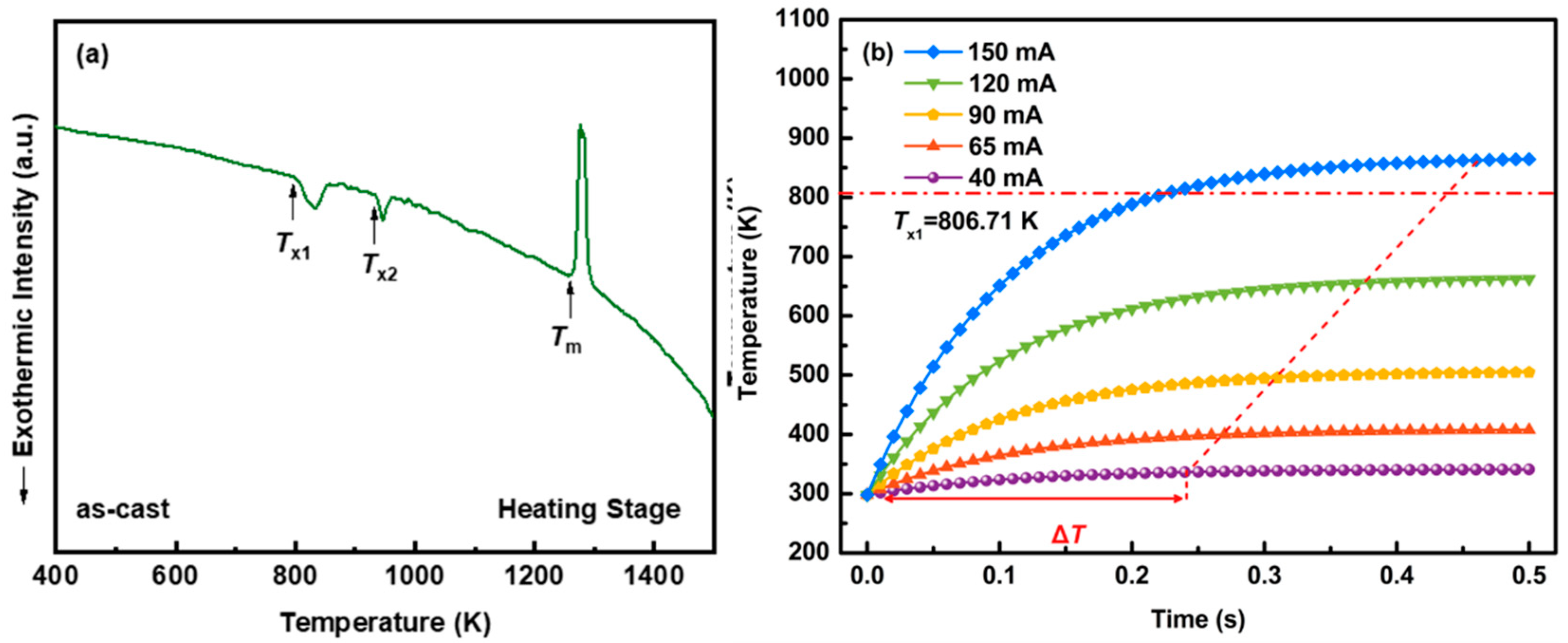
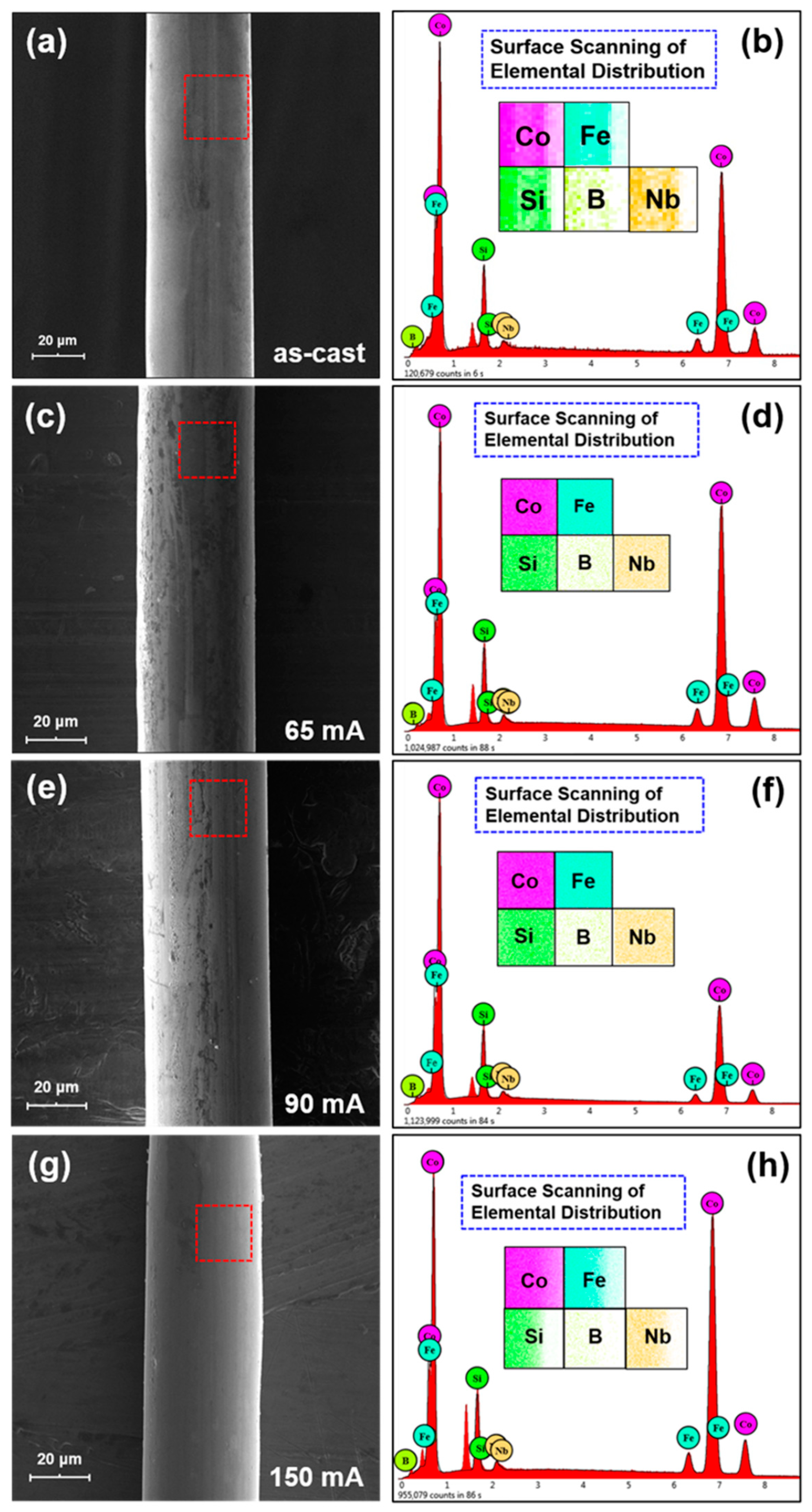
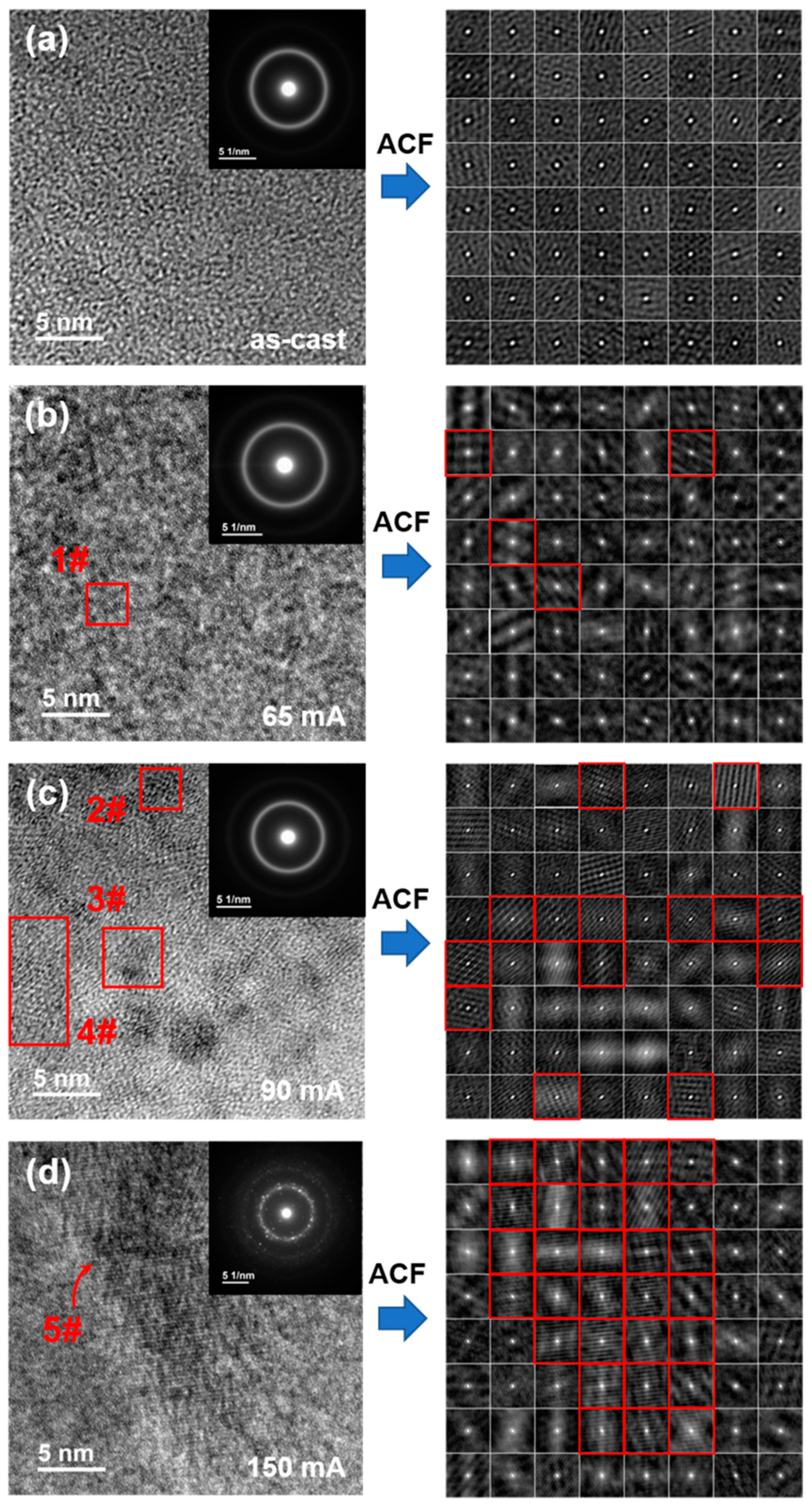
3.1. Direct Current Annealing and Structure Characteristic

The DSC curve of the as-cast Co-based metallic microwires shows that they have a typical amorphous structure with a crystallization temperature Tx1 of 806.71 K, as shown in Figure 2a. The numerical calculation of the transient temperature rising characteristic can effectively provide the current annealing experimental parameters, such as current amplitudes, based on Tx1 of metallic microwires [33,34]. Figure 2b is the transient (0–0.5 s) heating characteristics of the Co-based metallic microwires at different DC amplitudes calculated based on programming language, Fortran. The transient temperature rising of the metallic microwires during DC annealing can be regarded as an unsteady heat conduction process with an internal heat source. According to the classical heat transfer model, taking metallic microwires per unit area as the research object, the energy conservation equation is as follows [35]:
Q f Q e Q h Q r = 0  
Q f = ρ c d T d τ  
where, ρ is the density of metallic microwires, 7720 kg/m3; c is the specific heat capacity of metallic microwires, 463.1818 J/(kg·K); Qf is temperature variation of metallic microwires, J; Qe is Joule heat of current, J; Qh is convection heat transfer on the surface of metallic microwires, J; Qr is radiation heat exchange on the surface of metallic microwires, J. In Figure 1b, the temperature rising curves under different DC amplitudes increase rapidly within a certain time ΔT, and eventually tend to be stable, while the ΔT increases slightly, from 0.24 s at 40 mA to 0.46 s at 150 mA. Simultaneously, the temperature inside the metallic microwires rises significantly, and the temperatures at 40 mA, 65 mA, 90 mA, 120 mA and 150 mA at 0.5 s are 340.90 K, 407.75 K, 504.90 K, 662.37 K and 864.56 K, respectively, whose temperature reached above the crystallization temperature at a DC amplitude of 150 mA. Consequently, the current amplitudes for DC annealing in this study were 65 mA, 90 mA and 150 mA. Cut metallic microwires into a uniform length of 80 mm, clamp them at both ends of DC-stabilized power supply, and anneal for 480 s at the above current amplitudes.
SEM morphology and EDS energy spectrum of as-cast and current-annealed Co-based metallic microwires are exhibited in Figure 3. As shown in Figure 3a,c,e,g, the surface of the Co-based metallic microwires in the states of as-cast and current-annealed are both smooth, uniform and continuous without obvious macro- or microscopic defects. This indicates that the forming properties of the Co-based metallic microwires are defect free in the process of rotated-dipping, and the melt could be rounded into microwires under the action of their own tension and gravity. Furthermore, the current annealing has no effect on the surface morphology of the Co-based metallic microwires. The peak positions of the EDS energy spectrum before and after current annealing are accurate, and the element distribution on surface is uniform(the red squares in Figure 3a,c,e,g), as shown in Figure 3b,d,f,h. This reveals that the elements, such as Co, Fe, Si and Nb, were fully mixed and evenly distributed in the metallic microwires during the preparation process, and there is no obvious segregation of surface elements during the current annealing.
The microstructures of the as-cast and current-annealed metallic microwires were further characterized by high-resolution transmission electron microscopy (HRTEM), and the auto-correlation function (ACF) was used to quantitatively evaluate the degree of structure order (DSO) ψ [36,37]. Firstly, the HRTEM image was cut into square areas of equal area and divided into 64 small square areas, and then the divided square areas were subjected to ACF transformation one by one to determine the degree of structure order of the metallic microwires, which can be calculated by the following formula:
ψ = ς κ × 100 %
where ς is the number of ordered areas; κ is the total number of divided areas, κ = 64.
Figure 4a displays the HRTEM morphology of the as-cast metallic microwires, indicating that their microstructure has no obvious crystallization. The selected area electron-diffraction pattern is an amorphous halo, and its degree of structure order is 0, further indicating that the as-cast metallic microwires have an amorphous structure. Figure 4b is the HRTEM morphology of the metallic microwires after annealing at 65 mA, and on which, the tiny nanoclusters (region 1#) appear on the amorphous matrix. The selected area electron-diffraction pattern is still an amorphous halo, while the degree of structure order is 6.25%. After annealing at 90 mA current, it can be seen from the HRTEM image that a large number of nanoclusters appear and are evenly distributed in the amorphous matrix, as shown in the 2#, 3# and 4# regions in Figure 4c, with the selected area electron-diffraction pattern of an amorphous halo, and the degree of structure order of 21.86%. Figure 4d illustrates the HRTEM image of the metallic microwires annealed at 150 mA. It can be seen that a large-area atomic arrangement order region (region 5#) appears in the amorphous matrix, and the distribution of nanoclusters is more concentrated than that of the 90 mA current annealed. The selected area electron-diffraction pattern of which is a polycrystalline ring with a degree of structure order of 45.31%. The TEM results show that the current annealing promotes the appearance of nanoclusters in the amorphous matrix of metallic microwires, and with the rising of the annealing current intensity, the area of the nanoclusters increases, the distribution tends to be concentrated, and the degree of structure order increases.

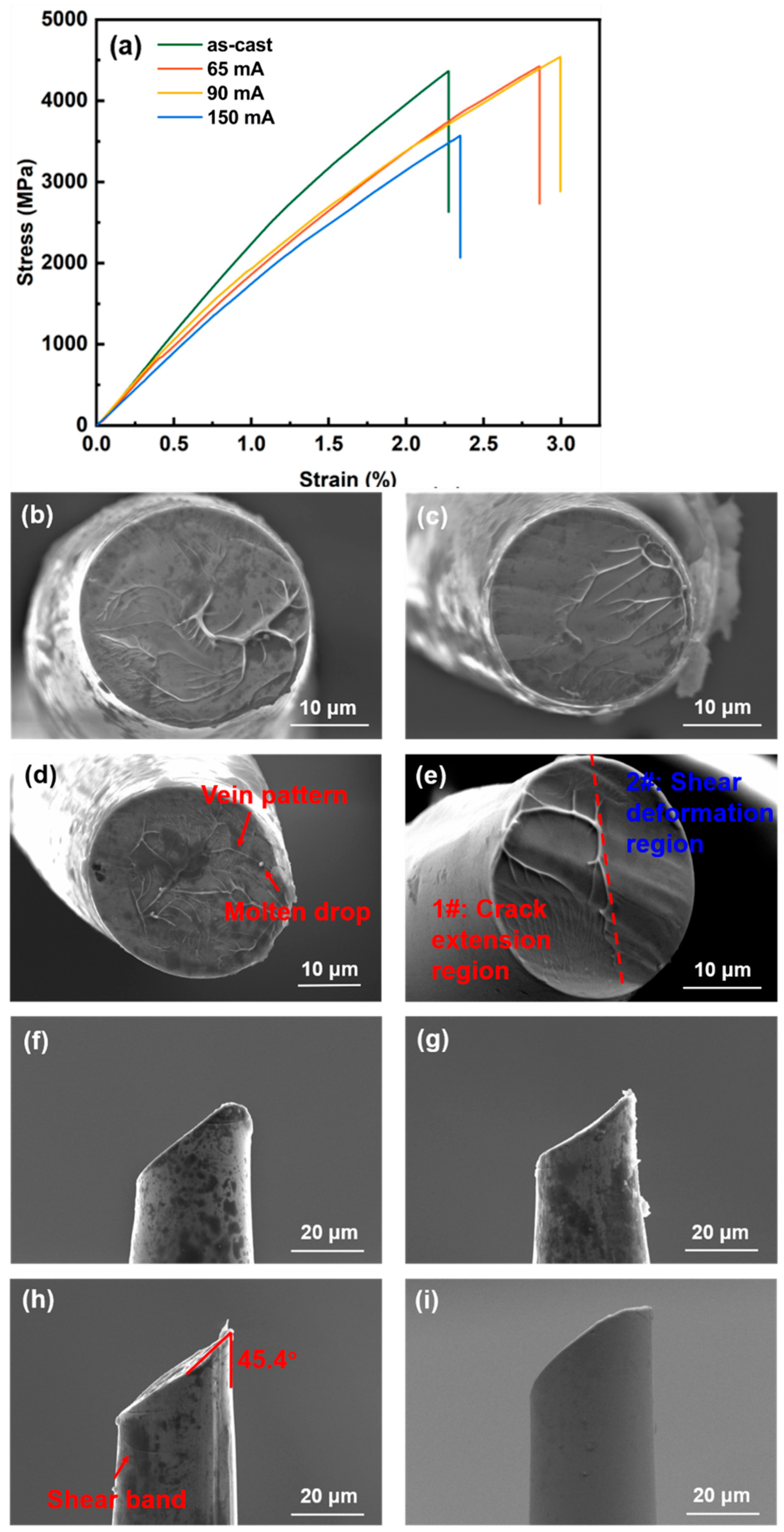
3.2. Tensile Properties and Fracture Morphology of Co-Based Metallic Microwires

For the purpose of ensuring the application of the Co-based metallic microwires in the field of stress sensors and broadening their application scenarios, it is necessary to undertake research into their mechanical properties and fracture reliability. Figure 5a plots the stress–strain curves of the as-cast and DC-annealed metallic microwires. With the rising of the annealing current intensity, the tensile strength and elongation at the break of the metallic microwires show a trend of increasing first and then decreasing, and both reach their peaks at the current intensity of 90 mA. The tensile strengths of the as-cast, 65 mA, 90 mA and 150 mA current annealed metallic microwires are 4366.79 MPa, 4424.89 MPa, 4540.10 MPa and 3425.23 MPa, respectively, and the elongation at break is 2.27%, 2.86%, 2.99% and 2.35%, respectively. The stress–strain curves of the as-cast and current annealed metallic microwires show the characteristics of the brittle fracture of amorphous alloys, that is, sudden fracture failure after elastic deformation. Further, the fracture process of the metallic microwires can be judged by observing the frontal fracture morphologies, as shown in Figure 5b–e. From this, the fracture is mainly composed of two typical regions: 1# the crack extension region and 2# the shear deformation region. The typical characteristics of the crack extension region are vein-like patterns and droplets, while the shear deformation region is a relatively flat instantaneous fracture zone. From the above, the fracture process of the metallic microwires can be inferred as follows: when the microwires are subjected to tensile force, the crack extension region bears a large stress and generates cracks; and with the increase in stress, the stress is mainly borne by part of the venation pattern, which has high energy and at the moment of fracture, the metallic microwires melt to form droplets, while the shear deformation region is formed rapidly at the moment of fracture, so the surface is relatively flat. Comparing the frontal fracture morphologies of the as-cast and annealed metallic microwires, it can be found that the frontal fracture of the microwires after annealing at 90 mA has a wider crack extension region and a denser venation pattern, which can better disperse the stress during the stretching process. Therefore, the 90 mA current-annealed metallic microwires exhibit a greater tensile strength. Figure 5f–i shows the side fracture morphologies of the as-cast and current-annealed metallic microwires. The fracture of these are an oblique fracture with a fracture angle of about 45°. The shear bands can be observed near the fracture of the microwires annealed at 90 mA, indicating that the initiation and expansion of the shear bands preferentially occur in metallic microwires under the action of stress, which delays the occurrence of instantaneous fracture.

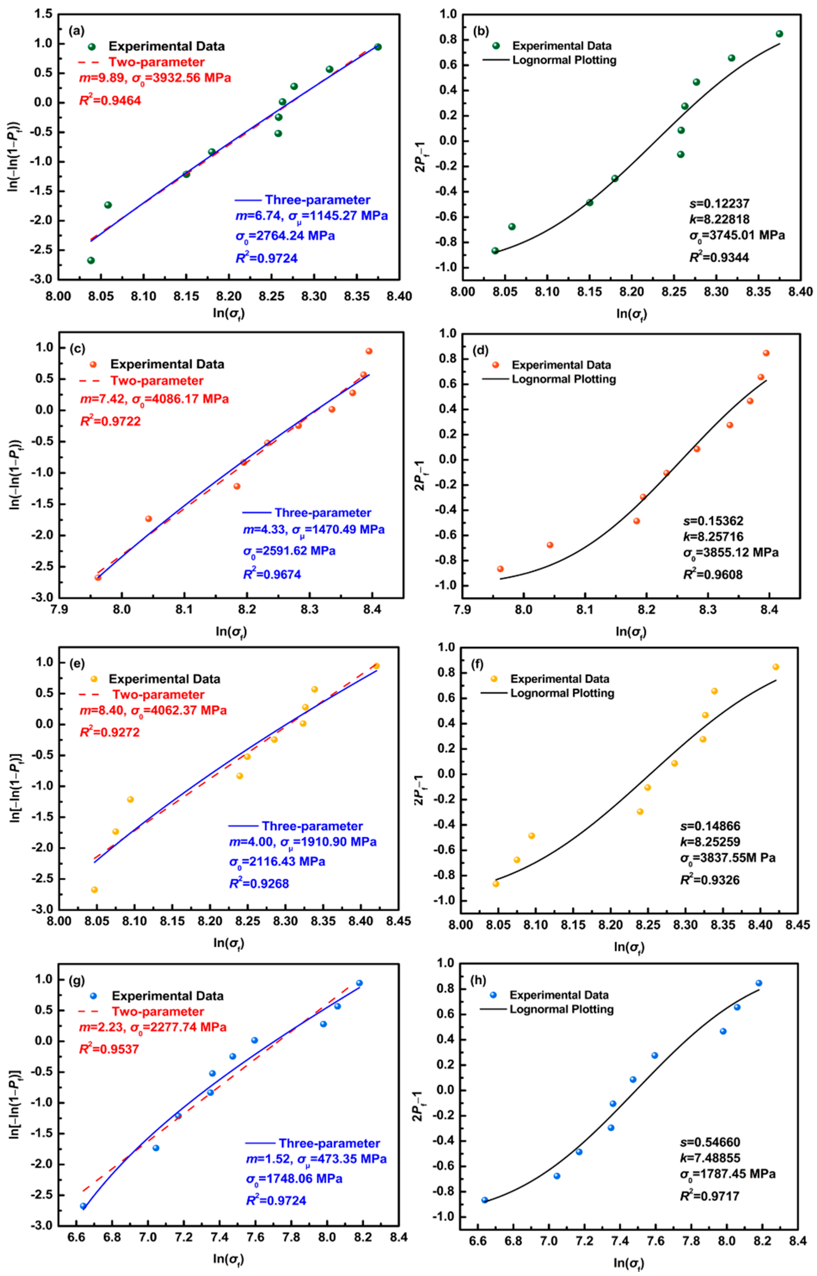
3.3. Fracture Reliability Analysis of Co-Based Metallic Microwires

The Weibull distribution is used to describe the fatigue degree of materials, which is the theoretical basis of reliability analysis and life test. Its probability density is as follows:
f ( x ; λ , k ) = { k λ ( x λ ) k 1 e ( x / λ ) k ,   x 0 0 ,   x < 0
where x is a random variable and λ > 0 is a shape parameter. Based on this, applying Weibull statistics and log-normal distribution fitting are suitable for the quantitative evaluation of the reliability and stability of the tensile strength of brittle materials, such as amorphous metallic microwires. The Weibull modulus m can represent the fracture reliability of the material, that is, a larger modulus m indicates that the tensile strength of the material is distributed in a narrow interval, while the fracture threshold σμ represents the safety of the material, that is, the probability of fracture of the material under this stress is zero. Specifically, it can be expressed as:
P f = 1 exp [ V   ( σ σ μ σ 0 ) m d V ]  
where the Pf represents the probability of fracture of the material under stress σ; σ0 is the scale parameter, representing the characteristic stress when the fracture probability is 63%; m is the Weibull modulus; σμ is the fracture threshold value; V is the sample volume. The three-parameter Weibull statistical formula can be obtained by linearizing Formula (6) as follows:
ln { ln [ 1 ( 1 P f ) ] } = m ln ( σ σ μ ) m ln σ 0  
as σμ is 0, (6) can be simplified to the two-parameter Weibull statistical Formula (7):
ln { ln [ 1 ( 1 P f ) ] } = m ln σ m ln σ 0  
The logarithmic distribution function can be expressed as:
P f = 1 2 [ 1 + erf ( ln ( σ ) k s 2 ) ]  
where s is the standard deviation and k is the mean value. According to the above Formulas (4)–(8), Weibull (two-parameter and three-parameter) and logarithmic fittings were performed on the tensile strengths of the as-cast and current-annealed metallic microwires, as shown in Figure 6, and the statistical parameters are listed in Table 2. The two-parameter Weibull modulus of the as-cast, 65 mA, 90 mA and 150 mA current-annealed microwires are: 9.89, 7.42, 8.40 and 2.23, respectively; the three-parameter Weibull modulus are: 6.74, 4.33, 4.00 and 1.52, respectively; the fracture thresholds are: 1145.27 MPa, 1470.49 MPa, 1910.90 MPa and 473.35 MPa; the standard deviations are: 0.12237, 0.15362, 0.14866 and 0.54660; the mean values are: 8.22818, 8.25716, 8.25259 and 7.48855, respectively. The two-parameter and three-parameter Weibull modulus decreases with the rising of the current intensity. The fracture threshold increased firstly and then decreased with the rising of the annealing current, and reached a peak at the current intensity of 90 mA. Current annealing increases the dispersion of tensile strength, and the 90 mA current-annealed metallic microwires have a better tensile strength reliability.
There are uniformly distributed and small-sized nanoclusters in the amorphous matrix of metallic microwires annealed at 90 mA current. During tensile deformation, shear bands are hindered as they extend to the edges of these nanoclusters, and passing through the nanoclusters generates several new shear bands of smaller size at the other end, and the shear bands are further expanded and delivered into a web, which in turn hinder the further expansion of the shear bands, resulting in better tensile mechanical properties [25], as shown in Figure 7a. After annealing at higher currents, the metallic microwires have a higher degree of crystallization, and there are large-area nanoclusters usually accompanied by the formation of brittle intermetallic compounds, which become shear-band initiation points. These regions will become the initiation points of the shear bands, and under the action of external stress, the shear bands will expand rapidly, causing the metallic microwires to break, and whose brittleness sensitivity increases, as shown in Figure 7b. In conclusion, with the increase in the annealing current strength, the tensile strength and elongation at the break of the metallic microwires increase first and then decrease, and reach the peak value when the current strength is 90 mA.

4. Conclusions

In this paper, the effect of direct current-annealing on the microstructure and the mechanical properties of the Co-based metallic microwires were systematically studied, and the mechanism of the effect of the content and distribution of nanoclusters on the mechanical properties was revealed. The main conclusions are as follows:
(1)
Direct current-annealing can promote the formation of nanoclusters in the amorphous structure of Co-based metallic microwires, and with the rising of the annealing current intensity, whose content increases, the distribution tends to be concentrated from dispersion;
(2)
Direct current-annealing with appropriate strength can effectively improve the tensile strength and elongation at the break of Co-based metallic microwires, and also enhance their fracture reliability. The 90 mA current-annealed metallic microwires have excellent tensile mechanical properties, the tensile strength and elongation at break are 4540.10 MPa and 2.99%, respectively, and the fracture threshold is 1910.90 MPa;
(3)
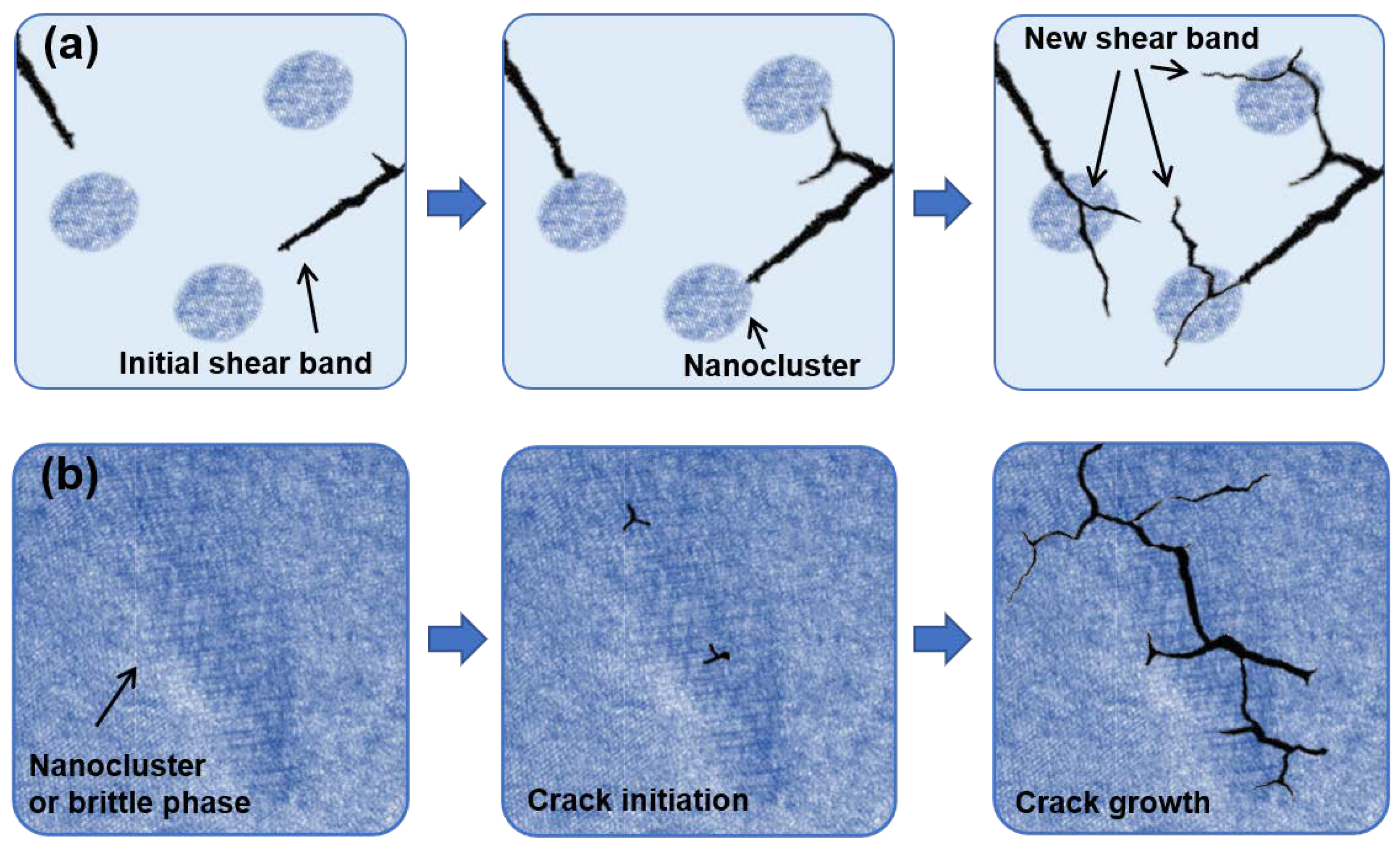
The way to improve the tensile mechanical properties of Co-based metallic microwires is to control the content and distribution of the nanoclusters. The small and uniformly distributed nanoclusters can hinder the expansion of shear bands, while the larger and concentrated nanoclusters may become the initiation points of shear bands and accelerate the generation of cracks.

Author Contributions

Conceptualization, J.L.; methodology, J.L., C.W. and G.C.; investigation, C.W., G.C., Y.Z. and F.W.; resources, J.L., R.L. and M.Z.; formal analysis, G.C.; writing—original draft preparation, C.W., G.C. and Y.Z.; writing—review and editing, supervision, R.L., M.Z., L.W. and Y.Z.; project administration, J.L.; funding acquisition, J.L. and B.Z. All authors have read and agreed to the published version of the manuscript.

Funding

This work was financially supported by the National Natural Science Foundation of China (NSFC) under grant nos. 52061035, 51871124, 51561026 and 51401111, the Ministry of Education Fok Ying-tung Foundation for Young Teachers (no. 161043), the “Grassland Talents” Project of Inner Mongolia Autonomous Region (no. CYYC9025), Inner Mongolia Natural Science Cultivating Fund for Distinguished Young Scholars (no. 2020JQ05), the Science and Technology Planning Project of Inner Mongolia Autonomous Region (no. 2020GG0267), the Program for Innovative Research Team in the Universities of Inner Mongolia Autonomous Region (no. NMGIRT2211), Inner Mongolia University of Technology Key Discipline Team Project of Materials Science (no. ZD202012).

Institutional Review Board Statement

Not applicable.

Informed Consent Statement

Not applicable.

Data Availability Statement

The data that support the findings of this study are available from the corresponding author, J.L., upon reasonable request.

Conflicts of Interest

The authors declare no conflict of interest.

References

  1. Schuh, C.A.; Hufnagel, T.C.; Ramamurty, U. Mechanical Behavior of Amorphous Alloys. Acta Mater. 2007, 55, 4067–4109. [Google Scholar] [CrossRef]
  2. Ding, D.J.; Huang, J.Z.; Deng, X.L.; Fu, K. Recent Advances and Perspectives of Nanostructured Amorphous Alloys in Electrochemical Water Electrolysis. Energy Fuels 2021, 35, 15472–15488. [Google Scholar] [CrossRef]
  3. Suryanarayana, C.; Inoue, A. Iron-based Bulk Metallic Glasses. Int. Mater. Rev. 2013, 58, 131–166. [Google Scholar] [CrossRef]
  4. Wang, W.H.; Dong, C.; Shek, C.H. Bulk Metallic Glasses. Mater. Sci. Eng. R-Rep. 2004, 44, 45–89. [Google Scholar] [CrossRef]
  5. Li, X.; Cai, W.Z.; Li, D.S.; Xu, J.; Tao, H.B.; Liu, B. Amorphous Alloys for Electrocatalysis: The Significant Role of the Amorphous Alloy Structure. Nano Res. 2021. [Google Scholar] [CrossRef]
  6. Gonzalez, A.; Zhukova, V.; CorteLeon, P.; Chizhik, A.; Ipatov, M.; Blanco, J.M.; Zhukov, A. Tuning of Magnetoimpedance Effect and Magnetic Properties of Fe-Rich Glass-Coated Microwires by Joule Heating. Sensors 2022, 22, 1053. [Google Scholar] [CrossRef]
  7. Jiang, S.D.; Wang, H.; Estevez, D.N.; Huang, Y.J.; Zhang, L.Y.; Shen, H.X.; Ning, Z.L.; Qin, F.X.; Sun, J.F. Surface Microstructural Design to Improve Mechanical and Giant Magneto-Impedance Properties of Melt-extracted CoFe-based Amorphous Wires. Mater. Des. 2021, 204, 109642. [Google Scholar] [CrossRef]
  8. Liu, J.S.; Zhang, Y.; Wang, Q.X.; Wu, M.J.; Nan, D.; Shen, H.X.; Peng, H.X. Enhanced Tensile Properties and Fracture Reliability of Cu-based Amorphous Wires via Pr-doping. Adv. Eng. Mater. 2018, 20, 1700935. [Google Scholar] [CrossRef]
  9. Shen, H.X.; Liu, J.S.; Wang, H.; Xing, D.W.; Chen, D.M.; Liu, Y.F.; Sun, J.F. Optimization of Mechanical and Giant Magneto-impedance (GMI) Properties of Melt-extracted Co-rich Amorphous Microwires. Phys. Status Solidi A-Appl. Mater. Sci. 2014, 211, 1668–1673. [Google Scholar] [CrossRef]
  10. Ogasawara, I.; Ueno, S.; Ohmichi, T. Preparation and Properties of Amorphous Wires. IEEE Trans. Magn. 1981, 31, 1219–1223. [Google Scholar] [CrossRef]
  11. Chiriac, H.; Óvári, T.A. Amorphous Glass-covered Magnetic Wires: Preparation, Properties, Applications. Prog. Mater. Sci. 1996, 40, 333–407. [Google Scholar] [CrossRef]
  12. Larin, V.S.; Torcunov, A.V.; Zhukov, A.; Gonzalez, J.; Vazquez, M.; Panina, L. Preparation and Properties of Glass-coated Microwires. J. Magn. Magn. Mater. 2002, 249, 39–45. [Google Scholar] [CrossRef]
  13. Atalay, F.E.; Kaya, H.; Atalay, S. Magnetoimpedance Effect in Electroplated NiFeRu/Cu Wire. J. Phys. D Appl. Phys. 2006, 39, 431–436. [Google Scholar] [CrossRef]
  14. Garcia, J.M.; Sinnecker, J.P.; Asenjo, A.; Vazquez, M. Enhanced Magnetoimpedance in CoP Electrodeposited Microtubes. J. Magn. Magn. Mater. 2001, 226, 704–706. [Google Scholar] [CrossRef]
  15. Mishra, A.C.; Sahoo, T.; Srinivas, V.; Thakur, A.K. Giant Magnetoimpedance in Electrodeposited CoNiFe/Cu Wire: A Study on Thickness Dependence. J. Alloys Compd. 2009, 480, 771–776. [Google Scholar] [CrossRef]
  16. Shen, H.X.; Wang, H.; Liu, J.S.; Xing, D.W.; Qin, F.X.; Cao, F.Y.; Chen, D.M.; Liu, Y.F.; Sun, J.F. Enhanced Magnetocaloric and Mechanical Properties of Melt-extracted Gd55Al25Co20 Micro-fibers. J. Alloys Compd. 2014, 603, 167–171. [Google Scholar] [CrossRef]
  17. Inoue, A.; Amiya, K.; Katsuya, A.; Masumoto, T. Mechanical Properties and Thermal Stability of Ti- and Al-based Amorphous Wires Prepared by a Melt Extraction Method. Mater. Trans. JIM 1995, 36, 858–865. [Google Scholar] [CrossRef]
  18. Nematov, M.G.; Baraban, I.; Yudanov, N.A.; Rodionova, V.; Qin, F.X.; Peng, H.X.; Panina, L.V. Evolution of the Magnetic Anisotropy and Magnetostriction in Co-based Amorphous Alloys Microwires due to Current Annealing and Stress-sensory Applications. J. Alloys Compd. 2020, 837, 155584. [Google Scholar] [CrossRef]
  19. Zhang, M.W.; Qu, G.D.; Liu, J.S.; Pang, M.Y.; Wang, X.F.; Liu, R.; Cao, G.Y.; Ma, G.X. Enhancement of Magnetic and Tensile Mechanical Performances in Fe-based Metallic Microwires Induced by Trace Ni-doping. Materials 2021, 14, 3589. [Google Scholar] [CrossRef]
  20. Liu, J.S.; Wang, X.F.; Li, Z.; Zhang, Y.; Cao, G.Y.; Huang, M.F.; Shen, H.X. Oil-medium Current Annealing Enhanced Giant Magneto-impedance Properties of Co-based Metallic Microfibers for Magnetic Sensor Applications. Mater. Today Commun. 2019, 20, 100605. [Google Scholar] [CrossRef]
  21. Liu, R.; Cao, G.Y.; Liu, J.S.; Li, Z.; Zhang, Y.; Liu, Z.T. Comparative Study on GMI Properties of Co-based Microwires Improved by Alcohol and Liquid Nitrogen Medium-Current Annealing. Mater. Res. Express 2021, 8, 065202. [Google Scholar] [CrossRef]
  22. Corte-Leon, P.; Zhukova, V.; Blanco, J.M.; González-Legarreta, L.; Ipatov, M.; Zhukov, A. Stress-induced Magnetic Anisotropy Enabling Engineering of Magnetic Softness of Fe-rich Amorphous Microwires. J. Magn. Magn. Mater. 2020, 510, 166939. [Google Scholar] [CrossRef]
  23. Dzhumazoda, A.; Panina, L.V.; Nematov, M.G.; Ukhasov, A.A.; Yudanov, N.A.; Morchenko, A.T.; Qin, F.X. Temperature-stable Magnetoimpedance (MI) of Current-annealed Co-based Amorphous Microwires. J. Magn. Magn. Mater. 2019, 474, 374–380. [Google Scholar] [CrossRef]
  24. Thiabgoh, O.; Shen, H.; Eggers, T.; Galati, A.; Jiang, S.; Liu, J.S.; Li, Z.; Sun, J.F.; Srikanth, H.; Phan, M.H. Enhanced High-frequency Magneto-impedance Response of Melt-extracted Co69.25Fe4.25Si13B13.5 Microwires Subject to Joule Annealing. J. Sci. Adv. Mater. Devices 2016, 1, 69–74. [Google Scholar] [CrossRef]
  25. Liu, J.S.; Li, Z.; Jiang, S.D.; Du, Z.X.; Shen, H.X.; Zhang, L.Y. Multiplex Magnetic Field Annealing Evoked Remarkable GMI Improvement in Co-based Amorphous Wires. J. Alloys Compd. 2016, 683, 7–14. [Google Scholar] [CrossRef]
  26. Prida, V.M.; Badini, G.; Vega, V.; Perez, M.J.; Batallan, F.; Vazquez, M. Magnetic Properties of Field Annealed Ni-rich Microwires. J. Non-Cryst. Solids 2007, 353, 931–934. [Google Scholar] [CrossRef]
  27. Corte-León, P.; Zhukova, V.; Ipatov, M.; Blanco, J.M.; Gonzalez, J.; Dominguez, L.; Churyukanova, M.; Zhukov, A. High Frequency Giant Magnetoimpedance Effect of a Stress-annealed Fe-rich Glass-coated Microwire. J. Alloys Compd. 2019, 802, 112–117. [Google Scholar] [CrossRef]
  28. Zhukov, A.; Zhukova, V.; Larin, V.; Gonzalez, J. Tailoring of Magnetic Anisotropy of Fe-rich Microwires by Stress Induced Anisotropy. Phys. B Condens. Matter 2006, 384, 1–4. [Google Scholar] [CrossRef]
  29. Zhukova, V.; Ipatov, M.; Talaat, A.; Blanco, J.M.; Churyukanova, M.; Zhukov, A. Effect of Stress Annealing on Magnetic Properties and GMI Effect of Co-rich and Fe-rich Microwires. J. Alloys Compd. 2017, 707, 189–194. [Google Scholar] [CrossRef]
  30. Wang, H.; Qin, F.X.; Xing, D.W.; Cao, F.Y.; Wang, X.D.; Peng, H.X.; Sun, J.F. Relating Residual Stress and Microstructure to Mechanical and Giant Magneto-impedance Properties in Cold-drawn Co-based Amorphous Microwires. Acta Mater. 2012, 60, 5425–5436. [Google Scholar] [CrossRef]
  31. Shen, H.X.; Xing, D.W.; Sánchez Llamazares, J.L.; Sánchez-Valdés, C.F.; Belliveau, H.; Wang, H.; Qin, F.X.; Liu, Y.F.; Sun, J.F.; Srikanth, H.; et al. Enhanced Refrigerant Capacity in Gd-Al-Co Microwires with a Biphase Nanocrystalline/Amorphous Structure. Appl. Phys. Lett. 2016, 108, 092403. [Google Scholar] [CrossRef]
  32. Zhukova, V.; Talaat, A.; Ipatov, M.; Del Val, J.J.; Gonzalez-Legarreta, L.; Hernando, B.; Zhukov, A. Effect of Nanocrystallization on Magnetic Properties and GMI Effect of Fe-rich Microwires. J. Electron. Mater. 2014, 43, 4540–4547. [Google Scholar] [CrossRef]
  33. Liu, J.S.; Huang, M.F.; Wu, M.J.; Zhang, Y.; Cao, G.Y.; Li, Z.; Chen, H.N.; Yu, T.C.; Wang, X.F.; Liu, R.; et al. Effect of Current Annealing Treatment on Magnetic Properties of Gd-Al-Co-Fe Metallic Microfibers. J. Alloys Compd. 2021, 855, 157231. [Google Scholar] [CrossRef]
  34. Liu, J.S.; Qin, F.X.; Chen, D.M.; Shen, H.X.; Wang, H.; Xing, D.W.; Phan, M.H.; Sun, J.F. Combined Current-modulation Annealing Induced Enhancement of Giant Magnetoimpedance Effect of Co-rich Amorphous Microwires. J. Appl. Phys. 2014, 115, 17A326. [Google Scholar] [CrossRef]
  35. Liu, J.S.; Cao, F.Y.; Xing, D.W.; Zhang, L.Y.; Qin, F.X.; Peng, H.X.; Xue, X.; Sun, J.F. Enhancing GMI Properties of Melt-extracted Co-based Amorphous Wires by Twin-zone Joule Annealing. J. Alloys Compd. 2012, 541, 215–221. [Google Scholar] [CrossRef]
  36. Xue, L.; Shao, L.L.; Luo, Q.; Hu, L.N.; Zhao, Y.B.; Yin, K.B.; Zhu, M.Y.; Sun, L.T.; Shen, B.L.; Bian, X.F. Liquid dynamics and glass formation of Gd55Co20Al25 metallic glass with minor Si addition. J. Mater. Sci. Technol. 2021, 77, 28–37. [Google Scholar] [CrossRef]
  37. Fan, G.Y.; Cowley, J.M. Auto-correlation analysis of high resolution electron micrographs of near-amorphous thin films. Ultramicroscopy 1985, 17, 345–355. [Google Scholar] [CrossRef]
Figure 1. Microfiber tensile testing system: (a) Instron 5943 electronic universal materials testing machine; (b) Screw side-action grips; (c) Microfiber tensile sample.
Metals 12 01427 g001
Figure 2. Determination of direct current-annealing strength: (a) DSC curve of as-cast metallic Co-based microwires; (b) Temperature rising at 0–0.5 s under different current intensities based on numerical calculation of transient temperature rise.
Metals 12 01427 g002
Figure 3. SEM microscopic morphology and EDS analysis of as-cast and direct current-annealed Co-based metallic microwires: (a,b) as-cast; (c,d) 65 mA; (e,f) 90 mA; (g,h) 150 mA.
Metals 12 01427 g003
Figure 4. HRTEM images, SAED and ACF of as-cast and direct current-annealed Co-based metallic microwires: (a) as-cast; (b) 65 mA; (c) 90 mA; (d) 150 mA.
Metals 12 01427 g004
Figure 5. (a) Stress–strain curves of as-cast and direct current-annealed Co-based metallic microwires. Fracture morphology of as-cast and direct current-annealed Co-based metallic microwires: (b) Front view, as-cast; (c) Front view, 65 mA; (d) Front view, 90 mA; (e) Front view, 150 mA; (f) Side view, as-cast; (g) Side view, 65 mA; (h) Side view, 90 mA; (i) Side view, 150 mA.
Metals 12 01427 g005
Figure 6. Fracture reliability analysis treated by multitype plotting (two- and three-parameter Weibull statistics and log-normal plotting) of as-cast and direct current-annealed Co-based metallic microwires: (a,b) as-cast; (c,d) 65 mA; (e,f) 90 mA; (g,h) 150 mA.
Metals 12 01427 g006
Figure 7. Schematic diagram of the effect of nanoclusters on shear bands and cracks: (a) Nanoclusters hinder propagation of shear bands; (b) Nanoclusters or brittle phase promote initiation and expansion of cracks.
Metals 12 01427 g007
Table 1. The chemical composition of Co-based metallic microwires.
ElementsContents (at.%)
Co69.25
Fe4.25
Si13.00
B12.50
Nd1.00
Table 2. Fracture reliability parameters of as-cast and direct current-annealed Co-based metallic microwires.
Fitting TypeAs-Cast65 mA90 mA150 mA
Weibull StatisticsTwo-parameterm = 9.89m = 7.42m = 8.40m = 2.23
Three-parameterm = 6.74m = 4.33m = 4.00m = 1.52
σμ = 1145.27 MPaσμ = 1470.49 MPaσμ = 1910.90 MPaσμ = 473.35 MPa
Log-normal Plottings = 0.12237s = 0.15362s = 0.14866s = 0.54660
k = 8.22818k = 8.25716k = 8.25259k = 7.48855
Publisher’s Note: MDPI stays neutral with regard to jurisdictional claims in published maps and institutional affiliations.

