Article

Control of Welding Residual Stress in Large Storage Tank by Finite Element Method

1
State Key Laboratory for Performance and Structure Safety of Petroleum Tubular Goods and Equipment Materials, CNPC Tubular Goods Research Institute, Xi’an 710077, China
2
College of Pipeline and Civil Engineering, China University of Petroleum (East China), Qingdao 266580, China
3
College of New Energy, China University of Petroleum (East China), Qingdao 266580, China
*
Author to whom correspondence should be addressed.
Metals 2022, 12(9), 1502; https://doi.org/10.3390/met12091502
Submission received: 25 July 2022 / Revised: 29 August 2022 / Accepted: 6 September 2022 / Published: 10 September 2022
(This article belongs to the Special Issue Residual Stress and Fatigue of Metals)

Abstract

:
T-joint welding is a key manufacturing process of large storage tanks. However, complex residual stresses are generated and have a great effect on the structural integrity of storage tanks. The high residual stress caused by welding and the discontinuous structure may result in tank cracking and failure. In this work, the residual stress distributions on the inner surface, outer surface, and thickness direction of the T-joint were investigated by using the finite element method and indentation test method. The effect of local PWHT with different heating temperatures, heating rates, and heating widths on the residual stress distribution was also discussed. Results show that the residual stress of the T-shaped joint is high due to the serious structure discontinuity, multi-layer welding, and high strength. Among all the stresses, the circumferential residual stress is the highest and most concentrated in the outer weld connected with the annular plate. The residual stress gradually decreases with the increase in the heat treatment temperature. When the heating rate is less than 106 °C/h, the residual stress gradually decreases with the decrease in the heating rate. The large thermal deformation caused by heat treatment can be simultaneously avoided by heating the inside and outside of the T-joint. The residual stress decreases with the decrease in the width of the heating zone. The residual stress can be regulated by using a smaller width in the heating zone. An optimized heat treatment scheme with a heating temperature of 700 °C, heating rate of 56 °C/h, and heating width of 200 mm was proposed, which has a good ability to control residual stresses and improve the quality of the T-joint. It also has a good application in engineering.

1. Introduction

With the development of the petroleum industry, storage tanks are gradually being developed at a large scale [1]. At present, the volume of super-large storage tanks exceeds 100,000 m3. The number of super-large storage tanks has been rapidly increasing year by year; therefore, the design and manufacturing level of super-large storage tanks must be improved [2]. Most tank failure cases occur at the T-joint due to the stress concentration [3].
Residual stress is caused by the expansion and contraction of the weld due to the heating and cooling of the welding process. Residual stress can easily cause stress concentration in the welded structures and increases the sensitivity of welds to fatigue damage, stress corrosion cracking, and fracture. Finite element analysis is a process of simulating real working conditions by using a limited number of simple and interactive elements. To date, many researchers have studied the welding residual stress distribution via finite element modeling, and it has become a popular tool for predicting residual stress. Siddique et al. [4] used a 3D simulation to study the influence of welding parameters on residual stress. Lee et al. [5,6] studied the residual stress of dissimilar steel welded joints through a 3D simulation and thermal elastoplastic analysis. Luo et al. [7,8] studied the residual stress distribution of different welded joints by the finite element method and experimental verification. Pandey et al. [9] presented the effect of welding direction on the residual deformation of double-sided fillet welds. They [10] also pointed out that 2D models can save a significant amount of computational time with reasonable accuracy. Luo et al. [11] studied the welding residual stress and deformation of ultra-large pressure vessels via a 3D finite element method. Shanmugam et al. [12] analyzed the temperature distribution of the laser welded T-joint by using a 3D finite element model. Piekarska et al. [13] simulated the deformation of a laser welded T-joint with ABAQUS and considered the various thermomechanical properties of the welding materials. Peric et al. [14] studied the residual stress and deformation of the two types of T-joints via a shell model and test. Teng et al. [15] studied the residual stress and deformation from the fillet welding of a T-joint via the finite element method and thermal elastoplastic analysis. The change of filling material with time is simulated by the element birth and death technique.
At present, the methods for reducing welding residual stress are mainly divided into in situ and post-welding regulation methods. The former is used to design a reasonable welding process and structure to control the tensile residual stress. Taraphdar et al. [16] investigated the effects of groove configuration, restraints, and mechanical tensioning on the residual stress distribution in a thick double-V butt weld joint, and the appropriate technologies were recommended. The latter releases residual stress by external heating or a mechanical method. The post-weld heat treatment (PWHT) is an appropriate method for controlling welding residual stresses. The PWHT can release the residual stresses and harmful gas in the metal, stabilize the shape and size of the structure, and improve the performance of the base of the metal and welding area and the ability to resist stress corrosion. However, conducting a furnace-based PWHT to release the residual stresses of a large storage tank is impractical due to its huge volume. The T-joints of a large storage tank are typically not subjected to PWHT, resulting in a cracking risk in the weld joint after long-time service. To assure the security of large storage tanks under long-time service, the local PWHT is recommended, as it is also the only possible choice. However, the effects of the local PWHT on the residual stresses of the T-joint of a large storage tank are unclear. The residual stress distribution of a large T-joint before and after a local PWHT must be studied. Some studies on the influence of heat treatment on residual stresses were performed. Chandan et al. [17] showed that heat treatment can reduce residual stress. Luo et al. [18] significantly reduced the residual stress by optimizing the heat treatment scheme. Jin et al. [19] studied the effect of primary and secondary local heat treatment on the residual stress of large pressure vessels via the finite element method and experiments. Wei et al. [20] studied the welding residual stress of the cracked joint of a large distillation column via the finite element method and experimental research. The results showed that the stress concentration caused by structural discontinuity is the main cause of the cracks. Geng et al. [21] studied the residual stress distribution after welding and the local heat treatment of ultra-thick-walled cylinders by using a plane strain 2D model. In summary, finite element methods can be used to study the effect of local heat treatment on residual stress.
According to the literature, the local PWHT has a good effect on releasing residual stresses in complex structures. Meanwhile, investigations of the local PWHT on T-joints made of 12MnNiVR are still insufficient. Accordingly, the mechanisms of releasing residual stresses and the optimum parameters of PWHT on T-joints made of 12MnNiVR have not been revealed. This situation necessitates a detailed investigation of the effect of local PWHT process technologies on the residual stress distribution of T-joints and of an effective PWHT scheme. In this work, a local PWHT scheme of T-joints made of 12MnNiVR is proposed to provide a reference for controlling the residual stresses of T-joints in engineering. The residual stress distributions along the inner surface, outer surface, and thickness of the weld were first investigated via the indentation test and finite element method to understand the distribution and evolution of the residual stress in the T-joint and to propose some methods for reducing residual stress. Then, the effects of the heat treatment factors, including heating temperature, heating rate, and heating width, on residual stress were studied by using the ABAQUS finite element software 6.14-5. The parameters of the optimized PWHT scheme were determined on the basis of the above-mentioned studies, providing a reference for engineering applications.

2. Experimental Procedure

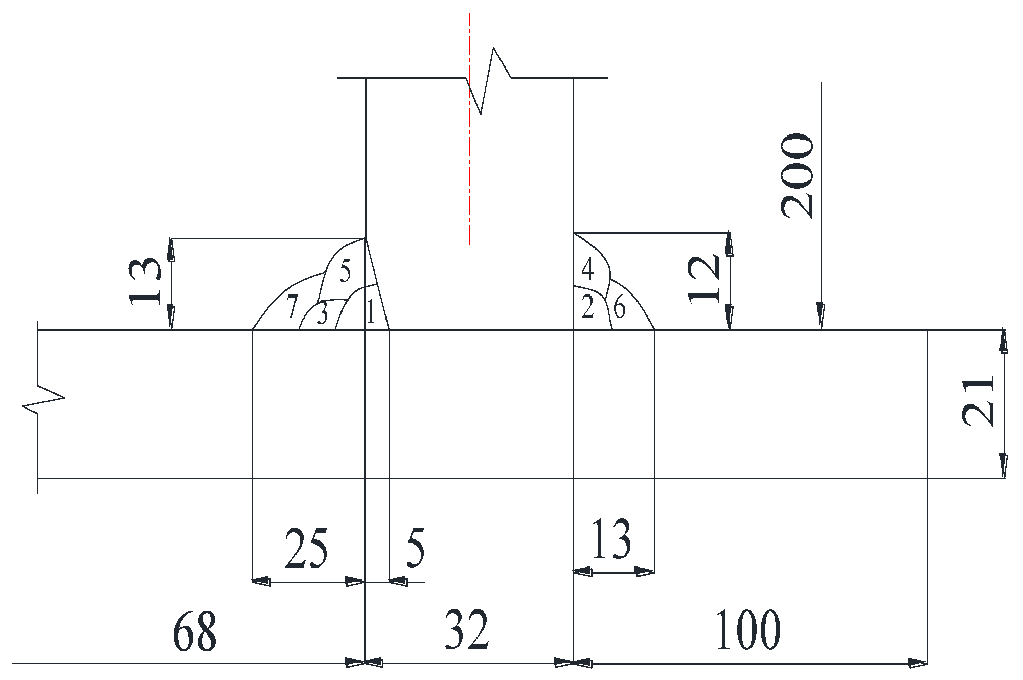
2.1. Specimen Preparation

From the point view of the local size of a T-joint of the large diameter of the tank, the T-joint of the tank can be assumed as the T-joint with a plate. The stress distribution of the T-joint of the tank can be approximately regarded as the same as that of the section of the welding test plate. The test plate T-joint is used in this study. The specimens were fabricated using thick plates made of 12MnNiVR low-alloy steel (500 L × 200 W × 32 T mm and 500 L × 200 W × 21 T mm), as shown in Figure 1. The chemical compositions (wt.%) of the base metal and filler metals are illustrated in Table 1, and the chemical compositions of the welding flux are shown in Table 2. Manual arc welding (MAW) and submerged arc welding (SAW) were used for root welding filling and cover welding, respectively. The electrode and welding parameters are shown in Table 3. Pass 1 is the root welding that uses the MAW method with a CHE607CG welding rod, and passes 2–4 (fill welding) and 5–7 (cover welding) use the SAW method with a CHW-S7CG welding rod. This process is widely used in tank welding to improve the welding efficiency to ensure the welding quality. According to the requirements of GB 50661-2011, the preheat temperature was 120 °C, and the inter-pass temperature was about 100 °C, which was achieved by the flame heating method. The welding flux is CHF26H, which should be dried at 350 °C for 1 h before use.

2.2. Residual Stress Measurement

The surface residual stresses after welding were measured by the indentation strain gauge method along paths L1, L2, and L3, as shown in Figure 2. Five points were measured on every path.
The indentation strain method [22] is one of the most widely used residual stress measurement methods because of its semi-destructive characteristics. The level of load is selected according to the different materials. The diameter of the indentation is 1.2 mm, and the depth is 0.2 mm. The measuring principle is shown in Figure 3. The test positions of the actual path are shown in Figure 4. When the impact load is applied, the impact indentation method adds an additional stress field to the original stress field to relax the residual stress, resulting in a strain increment compared with the specimen without residual stress. The residual elastic strain is calculated according to the relationship between the residual elastic strain and the strain increment under different indentation sizes. The residual stress measured by the indentation strain gauge method is calculated by using Equations (1) and (2) [23]:
σ T = E 1 v 2 ( ε e T + v ε e L )
σ L = E 1 v 2 ( ε e L + v ε e T )
where ε e T and ε e L are the transverse and longitudinal elastic strain increments due to residual stress and impact loads, whereas σ T and σ L represent the transverse and longitudinal residual stress.
The residual stress measurement requires four steps. Step 1: the measurement surface is ground with a grinding mill and polished with an emery cloth. Step 2: the strain gauges are pasted along the parallel and vertical directions to the weld. Step 3: the center of the impact device is kept concentric with the center of the measurement point. Step 4: the indentation is generated by the impact pin. The longitudinal and transverse residual elastic strains are measured by sticking the biaxial strain gauge parallel and perpendicular to the weld.

3. Finite Element Model Details

3.1. Finite Element Model

ABAQUS software 6.14-5 was used to calculate the finite element. The 2D axisymmetric model was adopted because of the large size of the storage tank, as shown in Figure 5. The structure and welding sequence are consistent with Figure 2. The dimensions of the bottom plate model, vertical plate model, left seam model, and right seam model are 910 L × 21 T mm, 630 L × 32 T mm, 24 D × 13 H mm, and 13 D × 13 H mm, respectively. The thermal–mechanical coupling model, equivalent heat source, and ideal elastic–plastic model were adopted in the welding process, which are carefully described in Section 3.2. The birth and death technology is used to simulate the shape change of the work piece by deleting and reactivating the mesh or contact pairs and was adopted in this model. Weld passes 1 to 7 were sequentially activated.
The model has 9138 elements and 9704 nodes. The effect of the quantity of mesh on the residual stress was considered. Figure 6 shows that the residual stress calculated by the number of elements, 9138 and 11,235, is basically consistent; thus, the number of elements, 9138, can ensure the calculation accuracy. The smallest mesh size is 0.64 mm × 0.6 mm. The DCAX4 (4-node linear axisymmetric heat-transfer quadrilateral) thermal element and CAX4R (4-node bilinear axisymmetric reduced-integration) stress element are used in the whole model during thermal and elastic–plastic analyses, respectively. During the welding and PWHT, the thermophysical and mechanical properties vary with temperature. The temperature-dependent material properties of 12MnNiVR, including the mechanical and thermal properties, are considered in the finite element analysis, as shown in Figure 7. Herein, the material properties of the weld and base metals are assumed to be the same. The mechanical properties are obtained from tests, such as the elastic modulus, Poisson’s ratio, and yield strength. The thermal property parameters were calculated using JMatPro software. JMatPro has a powerful metal material database that has been widely verified by experiments. The thermal performance parameters of the material can be obtained by inputting the chemical element composition of the material. The material parameters in the simulation are assumed to be constant when the temperature is above 1400 °C.

3.2. Thermal Analysis

The thermal-elastic-plastic analysis consists of the welding temperature and stress analyses and employs the temperature that was obtained from the thermal analysis. The 2D model with an endogenous heat source has better results and can greatly reduce the computational cost [24]. The welding temperature is simulated by applying a heat flux to the weld elements by using a ramp heat input model. This heat model is described in Ref. [25] in detail, which can be used to model the welding heat source and avoid the numerical convergence problems, as shown in Figure 8. The heat flux varies with time, simulating the movement of the heat source. The weld bead is heated to the maximum heat input within ramp time t1 (i.e., the heat source approaching process). Then, it stays constant until t2 to ensure melting. At last, it decreases to zero within t3. A ramp time of 20% of the total weld time gives the best correlation with the measurement data. In this work, t1, t2, and t3 are 0.1, 0.4, and 0.5 s, respectively.
The heat flux for each weld pass, DFLUX, is calculated by [20]:
DFLUX = η U I V
where η is the arc thermal efficiency, U is the arc voltage, I is the welding current, and V is the weld pass volume.
The heat transfer between model and environment was defined by Newton’s law for convection and Stefan–Boltzmann’s law for radiation, as shown in Equations (4) and (5), respectively:
q c = a c ( T T 0 )
q r = ε C 0 ( T 4 T 0 4 )
where ac = 2.5 × 10⁻⁵ J·mm2·s−1·K−1 is the convective heat transfer coefficient, ε = 0.85 is the absorption of steel, C0 = 5.67 × 10⁻¹⁴ J·mm2·S−1·K−1 is the Stefan–Boltzmann constant, and T0 is the ambient temperature [K].
After the welding simulation, the local PWHT simulations were conducted. The thermal cycle was applied to the heated zone of the local PWHT.

3.3. Mechanical Analysis

The effect of phase transformation on the low-carbon steel is not evident [22]; thus, phase transformation is not considered. Therefore, the residual stress was calculated according to the results of the thermal analysis, and the total strain increment consists of three components, as shown in Equation (6) [26]:
d ε = d ε e + d ε p + d ε th
The thermal strain is calculated by using the coefficient of thermal expansion related to temperature. The rate-independent plastic model for plastic strain uses the von Mises yield surface, temperature-dependent mechanical properties, and the isotropic hardening model, which are used for welding simulation because the tests required for model calibration are easy to carry out. Isotropic strengthening means that the loaded surface uniformly expands in all directions after the material enters the plastic deformation. However, the center and shape of the yield surface remain unchanged. The yield function is defined as Equation (7) [26]:
f ( σ i j , k ) = f 0 ( σ i j ) k ( k ) = 0 ,
where k(k) is a strengthening function used to determine the yield surface size.
No displacement boundary condition is set for the two ends of the tank bottom and the two vertices of the tank wall. The constraint points of the boundary conditions are shown in Figure 5.

4. Results

4.1. Analysis on Welding Residual Stress Distribution

The transverse and longitudinal residual stresses are high at the discontinuity due to the geometric discontinuity of the structure. The inner weld is tempered by the thermal cycle of the multi-pass weld; thus, the residual stress is relatively small. Furthermore, the circumferential residual stress of the outer weld is high after cooling. The S11, S22, and S33 of the 2D axisymmetric model correspond to the radial, axial, and circumferential stresses, respectively.
The residual stress calculation results are shown in Figure 9. The maximum value of the radial residual stress (S11) is 454 MPa, which is located at the tank bottom. The radial residual tensile stress at the discontinuous joint between the weld and tank bottom is 343 MPa, and the corresponding compressive stress is formed in the interior of the tank bottom.
The maximum residual axial stress (S22) is 438 MPa, which is located at the joint between the weld and the tank wall, and a certain compressive stress is formed in the interior of the tank wall. The hoop residual stress (S33) has a large value on the inside and outside of the weld. The maximum stress is 756 MPa, which is located at the joint between the weld and the tank floor.
During the welding heating, the deposited metal expands to produce compressive stress. The weld forms high residual tensile stress due to the constraint of the joint in the cooling process. The latter weld of the multi-layer welding has a post-thermal effect on the previous weld, which can reduce the residual stress of the inner weld. Thus, the residual stress is mainly in the outer layer of the weld.

4.2. Verification of Residual Stresses

The calculated and measured values of the residual stress on the inner and outer surfaces of the sample are compared according to the path shown in Figure 2, and the comparison results are shown in Figure 10 and Figure 11. The axial and hoop residual stress distributions of the inner and outer welds are analyzed because the radial residual stress is small.
The finite element calculation of the axial residual stress is in good agreement with the measured value, and its magnitude and trend can be reflected through the finite element calculation. The maximum axial residual stresses of the inner and outer welds are 408 and 439 MPa, respectively, which are both located at the joint between the weld and the tank wall. A high residual stress can also be observed at the joint between the weld and the tank wall and between the tank floor and the weld. When the last inner weld is cooled, the shrinkage of the inner weld forms tensile stress. Accordingly, a high axial residual stress is generated at the joint between the weld and the tank wall.
The maximum hoop residual stresses of the inner and outer welds are 682 and 678 MPa, respectively, which are both located inside the weld connected with the tank floor. The hoop residual stress in the weld zone is high, especially at the connection between the weld and the tank wall, weld, and tank floor.
The finite element calculation value of the hoop residual stress is basically consistent with the experimental value. The maximum error is 13%, which proves the reliability of the finite element model. The small error may be caused by: (1) a manual measurement error, (2) an assumption condition of the simulation, and (3) material parameter properties subject to actual manufacturing process errors.

5. Discussion

In actual practice, the storage tank is not subject to PWHT. According to the Section 4 analysis, the values of the hoop residual stress in the inner and outer welds are high. The residual stress must be reduced via heat treatment. The effect of the local heat treatment on residual stress is studied because the volume of the storage tank is large.
The heat treatment temperature, heating rate, and heating zone width were studied according to the requirements of GB/T 30583-2014. Path 1 was taken along the inner and outer surfaces of the weld, as shown in Figure 5. The hoop residual stress on the paths was selected to study the influencing factors of heat treatment because the hoop residual stress is much higher than the radial and axial residual stresses.
The S11, S22, and S33 of path 1 were selected to study the influencing factors of heat treatment because the overall hoop residual stress is high, and the safety requirement of the inside weld is considerable.

5.1. Effect of PWHT Temperature

The heat treatment temperatures of 600 °C, 650 °C, and 700 °C were selected to study in accordance with the requirements of GB/T30583-2014. The residual stresses under different heat treatment temperatures were obtained by finite element analysis. Figure 12 shows the radial, axial, and hoop residual stress distribution of path 1 with varying heating temperatures.
During the heat treatment, plastic deformation occurs within the metal under the action of residual stresses due to the reduction of the yield point, causing some residual stresses to be released. After heat treatment at different temperatures, the maximum residual stress moves from the two segments to the inside of the weld, and the residual stress distribution trend is the same. The axial residual stress has the maximum value at the joint between the weld and the tank wall. The hoop residual stress has the maximum value in the weld connected with the tank floor.
The distribution trend of the hoop residual stress gradually slows down, and the value becomes smaller with the increase in heat treatment temperature. The maximum values of the hoop residual stress of path 1 at 600 °C, 650 °C, and 700 °C are 511, 401, and 346 MPa, respectively.
When the temperature increases, the residual stress can be relaxed better because the uniformity of the structure increases, and the yield strength of the material decreases. Therefore, the heat treatment temperature of 700 °C is selected to study the other influencing factors of heat treatment.

5.2. Effect of PWHT Heating Rate

The heating rate is set to 56/76/96/106/136 °C/h within the allowable range of GB/T30583-2014. Figure 13 shows the radial, axial, and hoop residual stress distribution of path 1 with different heating rates.
The trend of the residual stress distribution slows down after different heat treatment rates. The axial residual stress has the maximum value at the joint between the weld and the tank wall. Meanwhile, the hoop residual stress has the maximum value inside the outer weld connected to the tank floor.
Except for the heating rate of 106 °C/h, the value of hoop residual stress decreases with the decrease in heating rate. The changes in the radial and axial residual stresses at different heating rates are evident, but they are much lower than the residual stress after welding.
The hoop residual stress of path 1 can be reduced by 49% when the heating rate is 56 °C/h. The main reason is that the temperature difference is small when heating slowly, and high thermal stress is avoided during the heat treatment.
The slower heating rate can achieve a good heat treatment effect and save energy consumption. Thus, the heating rate of 56 °C/h is selected for follow-up heat treatment research.

5.3. Effect of PWHT Width

According to GB/T 30853-2014, the heating width is HB = 7nhk (1 < n < 3) when the thickness is less than 50 mm, where hk is the maximum width of the weld. Different heating widths of 200, 400, 600, 800, 1000, and 1200 mm are arranged along the inner and outer walls of the tank, as shown in Figure 5. The heat treatment scheme was obtained by studying the above-mentioned factors. The heat treatment temperature of 700 °C and the heating rate of 56 °C/h were used to study the effect of heating zone width. Figure 14 shows the radial, axial, and hoop residual stress distribution of path 1 with different heating widths.
The value of the hoop residual stress gradually increases with the increase in the heating zone width. When the heating zone width is less than 600 mm, the changes in the radial and axial residual stresses with different heating widths are not evident. When the heating zone width is greater than 800 mm, the radial residual stress is greater than that after welding. The effect of the heat treatment is the best with a 200 mm heating zone width, and the maximum hoop residual stress can be reduced by 52%.
Therefore, the heat treatment temperature of 700 °C, the heating rate of 56 °C/h, and the heating zone width of 200 mm can greatly reduce the residual stress, especially the hoop residual stress.

6. Conclusions

In this work, the residual stress distribution caused by T-shaped fillet welding and a heat treatment is studied via the finite element method and experimental test. The 2D finite element model and equivalent heat source model were used in a numerical simulation. The influences of the PWHT factors on the residual stress were studied, including the heating temperature, heating rate, and heating zone width. The following conclusions may be drawn based on the obtained results:
(1)
The welding residual stress at the weld is high due to the discontinuity of the T-weld structure and the material characteristics of a high yield strength. The maximum value of the hoop residual stress can reach 756 MPa, which is located at the connection between the outer weld and the bottom plate of the tank.
(2)
The circumferential residual stress is mainly distributed in the outer weld because the inner weld is tempered by the outer weld.
(3)
The maximum radial residual stress is 454 MPa, which is mainly located at the bottom of the tank. The maximum axial residual stress is 438 MPa, which is mainly located at the joint between the weld and the tank wall.
(4)
The varying heat treatment temperature has a great influence on the residual stress. The effect of residual stress relief is better with the increase in temperature. The heat treatment temperature of 12MnNiVR is recommended to be 700 °C.
(5)
The residual stress reduction increases with the decrease in the heating rate. The residual stress is greatly reduced through the 56 °C/h heating rate. This effect is mainly due to the avoidance of thermal stress caused by the high heating rate.
(6)
The residual stress decreases when the inner and outer walls are arranged with a 200 mm heating zone width because the symmetrical distribution prevents large deformations and high stress from occurring.

Author Contributions

Methodology, Y.W.; formal analysis, Y.L. and S.Z.; data curation, Y.Z. and S.X.; writing—original draft preparation and writing—review and editing, G.W.; supervision, J.L. and L.L. All authors have read and agreed to the published version of the manuscript.

Funding

This research was funded by CNPC Research and Technology Development Project (2021DJ2804) and Opening Project Fund of the Materials Service Safety Assessment Facilities (MSAF-2020-006).

Data Availability Statement

Not applicable.

Conflicts of Interest

The authors declare no conflict of interest.

References

  1. Zhong, G.X.; Xiang-Yuan, X.I. Introduction of the Welding Equipment for the Large-Scale Oil Tank; Petro-Chemical Equipment: Beijing, China, 2007. [Google Scholar]
  2. GB 50341-2014; Code for Design of Vertical Cylindrical Welded Steel Oil Tanks. Chinses Standard Publisher: Beijing, China, 2014.
  3. Kim, J.S.; An, D.H.; Lee, S.Y.; Lee, B.Y. A failure analysis of fillet joint cracking in an oil storage tank. J. Loss Prev. Process Ind. 2009, 22, 845–849. [Google Scholar] [CrossRef]
  4. Siddique, M.; Abid, M.; Junejo, H.F.; Mufti, R.A. 3-D Finite Element Simulation of Welding Residual Stresses in Pipe-Flange Joints: Effect of Welding Parameters. Mater. Sci. Forum 2005, 490–491, 79–84. [Google Scholar]
  5. Lee, C.H.; Chang, K.H. Numerical analysis of residual stresses in welds of similar or dissimilar steel weldments under superimposed tensile loads. Comput. Mater. Sci. 2007, 40, 548–556. [Google Scholar] [CrossRef]
  6. Chang, K.H.; Lee, C.H. Finite element analysis of the residual stresses in T-joint fillet welds made of similar and dissimilar steels. Int. J. Adv. Manuf. Technol. 2009, 41, 250. [Google Scholar] [CrossRef]
  7. Luo, Y.; Jiang, W.; Wan, Y.; Woo, W.; Tu, S. Effect of helix angle on residual stress in the spiral welded oil pipelines: Experimental and finite element modeling. Int. J. Press. Vessel. Pip. 2018, 168, 233–245. [Google Scholar] [CrossRef]
  8. Luo, Y.; Zhang, Q.; Zheng, H.X.; Jiang, W. Reducing Full-Field Residual Stress of Girth Weld with Thick Wall by Combining Local PWHT and Water Jet Peening. J. Press. Vessel Technol. 2022, 144, 061302. [Google Scholar] [CrossRef]
  9. Pandey, C.; Giri, A.; Mahapatra, M.M. On the Prediction of Effect of Direction of Welding on Bead Geometry and Residual Deformation of Double-sided Fillet Welds. Int. J. Steel Struct. 2016, 16, 333–345. [Google Scholar] [CrossRef]
  10. Taraphdar, P.K.; Kumar, R.; Pandey, C.; Mahapatra, M.M. Significance of Finite Element Models and Solid-State Phase Transformation on the Evaluation of Weld Induced Residual Stresses. Met. Mater. Int. 2021, 27, 3478–3492. [Google Scholar] [CrossRef]
  11. Luo, Y.; Jiang, W.; Yang, Z.; Wang, C.; Jin, Q.; Gao, T.; Yan, G.; Tu, S.; He, Y. Using reinforce plate to control the residual stresses and deformation during local post-welding heat treatment for ultra-large pressure vessels. Int. J. Press. Vessel. Pip. 2021, 191, 104332. [Google Scholar] [CrossRef]
  12. Shanmugam, N.S.; Buvanashekaran, G.; Sankaranarayanasamy, K.; Kumar, S.R. A transient finite element simulation of the temperature and bead profiles of T-joint laser welds. Int. J. Model. Simul. 2010, 30, 108–122. [Google Scholar] [CrossRef]
  13. Piekarska, W.; Kubiak, M.; Saternus, Z. Numerical Simulation of Deformations in T-Joint Welded by the Laser Beam. Arch. Metall. Mater. 2013, 58, 1391–1396. [Google Scholar] [CrossRef] [Green Version]
  14. Perić, M.; Tonković, Z.; Rodić, A.; Surjak, M.; Garašić, I.; Boras, I.; Švaić, S. Numerical analysis and experimental investigation of welding residual stresses and distortions in a T-joint fillet weld. Mater. Des. 2014, 53, 1052–1063. [Google Scholar] [CrossRef]
  15. Teng, T.L.; Fung, C.P.; Chang, P.H.; Yang, W.C. Analysis of residual stresses and distortions in T-joint fillet welds. Int. J. Press. Vessel. Pip. 2001, 78, 523–538. [Google Scholar] [CrossRef]
  16. Taraphdar, P.K.; Kumar, R.; Giri, A.; Pandey, C.; Mahapatra, M.M.; Sridhar, K. Residual stress distribution in thick double-V butt welds with varying groove configuration, restraints and mechanical tensioning. J. Manuf. Process. 2021, 68, 1405–1417. [Google Scholar] [CrossRef]
  17. Pandey, C.; Mahapatra, M.M.; Kumar, P. A comparative study of transverse shrinkage stresses and residual stresses in P91 welded pipe including plasticity error. Arch. Civ. Mech. Eng. 2018, 18, 1000–1011. [Google Scholar] [CrossRef]
  18. Luo, Y.; Gao, T.; Jiang, W. An Optimized Heat Treatment Process to Reduce the Weld Residual Stress by Auxiliary Heating. In Proceedings of the ASME 2019 Pressure Vessels & Piping Conference, San Antonio, TX, USA, 14–19 July 2019. [Google Scholar]
  19. Jin, Q.; Jiang, W.; Gu, W.; Wang, J.; Li, G.; Pan, X.; Song, M.; Zhang, K.; Wu, A.; Tu, S.T. A primary plus secondary local PWHT method for mitigating weld residual stresses in pressure vessels. Int. J. Press. Vessel. Pip. 2021, 192, 104431. [Google Scholar] [CrossRef]
  20. Peng, W.; Jiang, W.; Jin, Q.; Wan, Y.; Luo, Y.; Ren, L.; Zhang, K.; Tu, S.T. Reduction of welding residual stress in the head-cylinder joint of a large rectifying tower by finite element method and experimental study. Int. J. Press. Vessel. Pip. 2021, 191, 104311. [Google Scholar] [CrossRef]
  21. Geng, L.; Tu, S.T.; Gong, J.; Jiang, W.; Zhang, W. On Residual Stress and Relief for an Ultra-Thick Cylinder Weld Joint Based on Mixed Hardening Model: Numerical and Experimental Studies. J. Press. Vessel Technol. 2018, 140, 041405. [Google Scholar] [CrossRef]
  22. Lin, Q.; Chen, H.; Chen, J.; Liang, Y. Residual stresses measurement using an indentation made by an impact load. Mater. Sci. Forum 2005, 490–491, 196–201. [Google Scholar]
  23. GB/T 24179-2009; Metallic Materials-Residual Stress Determination-The Indentation Strain-Gage Method. Chinses Standard Publisher: Beijing, China, 2009.
  24. Jiang, W.C.; Tu, S.D.; Sun, G.A. Neutron Diffraction Measurement, Computation and Control of Welding Residual Stress; Science Press: Beijing, China, 2019. [Google Scholar]
  25. Jiang, W.; Woo, W.; Wan, Y.; Luo, Y.; Xie, X.; Tu, S.T. Evaluation of through-thickness residual stresses by neutron diffraction and finite-element method in thick weld plates. J. Press. Vessel Technol. 2017, 139, 031401. [Google Scholar] [CrossRef]
  26. Deng, D. FEM prediction of welding residual stress and distortion in carbon steel considering phase transformation effects. Mater. Des. 2009, 30, 359–366. [Google Scholar] [CrossRef]
Figure 1. Welding sample structure (unit: mm).
Metals 12 01502 g001
Figure 2. Positions in residual stress measurement.
Metals 12 01502 g002
Figure 3. The measurement principle of indentation strain gauge method.
Metals 12 01502 g003
Figure 4. The measurement process of indentation strain gauge method.
Metals 12 01502 g004
Figure 5. Finite element model.
Metals 12 01502 g005
Figure 6. Grid independence verification.
Metals 12 01502 g006
Figure 7. Temperature dependent material properties.
Metals 12 01502 g007
Figure 8. Ramp heat input model.
Metals 12 01502 g008
Figure 9. Residual stress distribution: (a) radial, (b) axial, (c) hoop.
Metals 12 01502 g009
Figure 10. Residual stress distribution of path 1. (a) Axial residual stress, (b) hoop residual stress.
Metals 12 01502 g010
Figure 11. Residual stress distribution of path 2. (a) Axial residual stress, (b) hoop residual stress.
Metals 12 01502 g011
Figure 12. Effect of PWHT temperature on the residual stress distribution of path 1: (a) radial, (b) axial, (c) hoop residual stress.
Metals 12 01502 g012
Figure 13. Effect of PWHT heating rate on the residual stress distribution of path 1: (a) radial, (b) axial, (c) hoop residual stress.
Metals 12 01502 g013
Figure 14. Effect of PWHT width on the residual stress distribution of Path 1: (a) radial, (b) axial, (c) hoop residual stress.
Metals 12 01502 g014
Table 1. Chemical composition of base metal and filler metals (wt.%).
CompositionCMnSiMoNiSPCrVTi
CHE607CG0.0701.440.260.270.940.0060.013///
CHW-S7CG0.0061.700.150.530.0250.0080.010.020.0040.10
12MnNiVR0.0941.700.150.070.210.0080.010.020.0460.011
Table 2. Chemical composition of welding flux (wt.%).
CompositionSiO2CaO + MgOMnOTiO2 + Al2O3CaF2
CHF26H20~4030~405~105~1515~30
Table 3. Welding parameters.
PassMethodElectrodeDiameter (mm)Current (A)Voltage (V)Welding Speed (cm/min)
1SMAWCHE607CG4.0200–24018–24/
2SAWCHW-S7CG2.4380–46030–3618–26
3SAWCHW-S7CG2.4380–46030–3618–26
4SAWCHW-S7CG2.4380–46030–3618–26
5SAWCHW-S7CG2.4380–46030–3618–26
6SAWCHW-S7CG2.4380–46030–3618–26
7SAWCHW-S7CG2.4380–46030–3618–26
Publisher’s Note: MDPI stays neutral with regard to jurisdictional claims in published maps and institutional affiliations.

