Article

Digital Reconstruction of Engineered Austenite: Revisiting Effects of Grain Size and Ausforming on Variant Selection of Martensite

Department of Materials Science and Engineering, National Taiwan University, Taipei 10617, Taiwan
*
Author to whom correspondence should be addressed.
Metals 2022, 12(9), 1511; https://doi.org/10.3390/met12091511
Submission received: 14 August 2022 / Revised: 6 September 2022 / Accepted: 7 September 2022 / Published: 13 September 2022

Abstract

:
In this work, the variant selection of martensite in a stainless maraging steel was investigated by electron backscattering diffraction and a new protocol of parent phase reconstruction. The reconstruction protocol enables digital austenite reversion into prior austenite microstructure and provides information of variant selection from a large number of austenite grains. It was found that strong variant selection occurred when the prior austenite grains were significantly refined in annealing or severely deformed by ausforming. When the prior austenite grain size was finer than 20 μm, it was found that a pair of twinned variants dominated in one packet, which dominates the prior austenite grain. This finding is explained by the inefficient space left by the early transformed martensite in the dominant packet. In contrast, variants with the same Bain orientation occupied most of the space of the austenite when the strain of the austenite exceeded 50%. The accumulated microbands on the 1   1   1 plane acted as nucleation sites of specific variants of martensite. This work provides statistical results to revisit the variant selection of martensitic transformation with the assistance of computational crystallography.

Graphical Abstract

1. Introduction

In steels, it is always important to optimize the mechanical property performance by controlling different kinds of matrices such as ferrite, martensite and bainite in steels [1]. Martensitic steel and tempered martensitic steel are widely used for structural applications including tool, energy engineering, automotive and aerospace. The transformation from austenite (parent) to martensite (daughter) is usually achieved by quenching or rapid cooling from a high temperature. In martensitic transformation, there are 24 equivalent variants of martensite able to form in one prior austenite grain based on transformation crystallography, or said orientation relationship (OR). Ideally, these 24 variants should occupy the prior austenite grain in the same volume fraction [2,3]. However, austenite can be engineered by a series of thermal or thermo-mechanical processes at high temperature. Prior austenite grains under different conditions such as grain size, texture or stored strain will give rise to non-equal fractions of these variants. Only a portion of these 24 variants contribute to the final microstructure, producing a strong transformation texture. This phenomenon is called variant selection [4]. It has been known that the microstructure of martensite affects mechanical properties including strength [5,6], toughness [7,8,9] and susceptibility to hydrogen embrittlement [10,11,12]. It is essential to revisit variant selection for a better understanding of the relationship between the condition of austenite and product microstructure.
There have been many studies on effects of ausforming on variant selection [13,14,15,16,17,18,19,20]. As the strain in austenite increases, martensite shows a stronger transformation texture and the variant selection is dominated by variants from the same packet [15]. It was proposed that the 1   1   1 slip plane in the deformed austenite serves as a nucleus of martensite transformation, and the product variants prefer to select the packet group of the same 1   1   1 plane. Hence, the variants of the packet group with the habit plane parallel to the primary or secondary slip plane tend to form first and occupy a large volume of prior austenite grain (PAG). The variant selection of martensite also appears when the prior austenite grain size (PAGS) is fine. It is proposed that variants with the habit plane almost parallel to the boundaries parallel to the rolling direction were preferentially selected [21]. In addition, the PAGS affects the packet size and the packet size determines the appearance of the sub-blocks [3]. Moreover, variant selection is observed under a coupled effect by grain size and deformation [22,23]. In the study of variant selection, the relationship between austenite and martensite is necessary. However, crystallographic information of prior austenite is frequently not accessed after martensitic transformation. Today, the digital data of crystallography mapping from electron backscattered diffraction (EBSD) makes it possible to explore the crystallographic information of the parent phase. The OR between austenite and martensite can be applied to compute backward the crystallographic status of prior austenite from the crystallography mapping of bainite and martensite. This technique is called parent phase reconstruction (PPR).
Humbert et al. first reported a series of reconstruction methods and applied them to study titanium alloys [24]. Cayron et al. developed a method based on “neighbor-to-neighbor” reconstruction, which was successfully applied to steels. This method uses a groupoid structure to analyze martensite variants, and their orientation operators are used to reconstruct parent grains [25,26,27]. Blaineau et al. also published a similar approach [28,29]. It uses four adjacent daughter grains, which obey the given OR, to form an initial group and then the group is expanded if the neighbor grains hold the same OR. This method allows automatic and large-area reconstruction. However, incorrect reconstruction frequently occurs in these methods. A direct and automatic approach was developed by Miyamoto et al. [30]. In this approach, the orientation of prior austenite is determined by optimizing the OR matrix through the minimization of the average reconstructed deviation over a local region. The algorithm repeats the above process region by region to accomplish global reconstruction. It has been successfully applied to reconstruct the orientation of ausformed austenite from the EBSD data of martensite [16,17]. However, the orientation of austenite might not be determined when the region covers two PAGs. Hence, there will be a loss of reconstruction near the PAG boundaries. In this work, we will apply a PPR protocol modified from our previous work to study the effects of grain size and ausforming on the variant selection of martensitic transformation. The reconstruction protocol enables statistical analyses on a large number of austenite grains.

2. Materials and Methods

2.1. Materials and Experimental Procedure

The material mainly discussed in this work is Custom 475 steel, which is a maraging stainless steel, designed by Carpenter Technology Corporation (Philadelphia, PA, USA) [31]. The chemical composition of Custom 475 is shown in Table 1 and details about the material preparation are given in our previous work [32]. Austenite is a face-centered cubic (FCC) crystal. Martensite, in this alloy, can be regarded as a body-centered cubic (BCC) crystal because its lattice constant ratio c/a is extremely close to 1 due to a low carbon content. Therefore, the martensitic transformation in this work is close to the FCC-to-BCC transformation.
To discuss the variant selection phenomenon for different grain sizes and deformed structures, the experiment was divided into two stages. The first stage was the importation of different prior austenite grain sizes in each specimen, for which the heat treatment was designed as shown in Figure 1a. Four distinct austenization temperatures were expected to create different results of prior austenite grain size. To simplify these conditions of heat treatment, we hereafter denote them as 900 °C, 1000 °C, 1150 °C and 1280 °C. The second stage was the deformation of the prior austenite to introduce an ausformed martensite structure. The heat treatment is shown in Figure 1b. The 1 h of austenization was expected to produce the proper grain size of austenite, and the 30% and 50% hot rolling could introduce different levels of deformation into the material. To simplify these conditions of heat treatment, we hereafter refer to them as sample A (30%) and sample B (50%).
The EBSD technique was used to explore the microstructure in this work, especially the crystal orientation. The specimens were ground mechanically using SiC sandpaper. The EBSD experiments were conducted on an FEI Nova450 FEG-SEM (Hillsboro, NH, USA) equipped with EBSD detector manufactured by EDAX (Pleasanton, CA, USA). The operating condition was a working distance of 10 mm with 20 keV voltage and a spot size of 5.5. The step size was set to 0.2 μm and the scanning area was 100 μm × 100 μm. However, this parameter was changed when the grain size was too large. The results were analyzed using TSL OIM Analysis 7.3 (Pleasanton, CA, USA).

2.2. New PPR Protocol

The PPR protocol, i.e., the digital austenite reversion, is briefly introduced here. When the orientation of austenite ( A ) is known, 24 variants of martensite can be generated by:
J S v A   =   M v   v   =   1 24 ,
where J is the transformation matrix (orientation relationship) from austenite to martensite; A and M are the orientation matrices of austenite and martensite, respectively; S is the symmetry operation matrices; and v denotes the number of variants. Austenite reconstruction can be governed by the equation:
A i   =   J 1 S i M   i   =   1 24 ,
where A i is a potential solution to the orientation of prior austenite corresponding to the symmetry operation matrices, S i . Hence, when each martensite variant gives 24 potential solutions, there will be, at most, 576 austenite orientations. In fact, austenite reconstruction is a process to find the correct S i for every pixel of martensite. In practical calculations, we can assume that the reconstructed orientation deviates from the real orientation of PAG. Therefore, the governing equation can be:
A i   =   D S j J 1 S i M   i   =   1 24 ,
where D is the deviation matrix and S j is the symmetry operation matrices. Miyamoto et al. used Equation (3) to develop an accurate reconstruction approach [30]. Recently, Huang and Yen established a protocol of austenite reconstruction, which enables a rapid and automatic reconstruction using three steps: orientation refinement, orientation coalescence and regional voting [33]. In this protocol, Equation (3) is used to refine the OR and J, and pixels of martensite of similar orientation are grouped to increase the computation speed. A voting process is executed to determine S j and, finally, the global reconstruction is done by Equation (2). This protocol was implemented into AztecCrystal, which is the EBSD software developed by Oxford Instruments (Abingdon, UK). However, particularly in ausformed austenite, the orientations of martensite are scattered due to misorientation in the austenite interior. Hence, austenite reconstruction becomes even more difficult. In this work, we modify the original protocol by replacing regional voting with boundary voting. In addition, a new step, solution tuning, is added to correct wrong reconstruction. Orientation refinement and orientation coalescence are still the first two steps in the new protocol.
The “boundary voting” algorithm calculates the pixels along both sides of the group boundary and accumulates the votes. For this purpose, Equation (3) can be further derived into:
J 1   S i   P X ,   A       =   D S k   J 1   S j   P Y , B     i ,     j ,     k   =   1 24   a n d     A     B   ,
where P X ,   A and P Y ,   B are two pixels from the group boundary in Group A and Group B, respectively, as shown in Figure 2a. A potential orientation calculated from P X ,   A is marked by A A ,   i = J 1   S i   P X ,   A and a potential orientation calculated from P Y ,   B is marked by A B ,   j = J 1   S j   P Y ,   B . The deviation angle, Δ θ , between two orientations is the minimum deviation angle obtained from 24 deviation matrices, D S k . Now, any of the 24 orientations from P X ,   A can be taken as the trunk of a tree, and its deviation angles with 24 orientations from P Y ,   B are calculated using Equation (4). Only the orientations with deviation angles lower than θ B = 5 ° are taken as branches, where Δ θ B is the branch angle [33]. Votes are calculated by a voting function:
V Δ θ = Δ θ B Δ θ ,
where   Δ θ is the deviation angle between the branch orientation and the trunk orientation. Every orientation solution of every group has the chance to be a trunk, and votes will be accumulated for each S i of Group A along the boundary. In each individual group, the solution S i accumulating the most votes is determined to be the group solution, S * A . This solution will be applied for every pixel in Group A. When the group solution of every group is determined, the global reconstruction is executed pixel-by-pixel by:
A n = J 1 S * M P n   p i x e l   n   b e l o n g   t o   G r o u p   M
where A n is the orientation of austenite reconstructed from the pixel n. Boundary voting emphasizes the relationship along the boundaries of groups. This would make the algorithm more sensitive to the orientation variation that results from the martensite variant or plastic deformation. Details about the tree–trunk–branch relationship can be found in our previous publication [33].
In fact, reconstruction is completed in boundary voting. However, misorientation in prior austenite due to ausforming can still cause incorrect reconstruction. To solve this problem, the “Solution Tuning” algorithm was used to optimize the results. The first step of this algorithm is to determine the “stable” and “unstable” austenite, as shown in Figure 2b. The criterion is a minimum area of reconstructed austenite grain, which is denoted as “Areamin”, and it is set as 100 pixels in this work. Here, the austenite grain is defined by a disorientation larger than 10°. A reconstructed austenite grain is marked as unstable when its area is smaller than Areamin and marked as stable when its area exceeds Areamin. The solution, S * M , of the unstable grain will be replaced by one of the other 23 potential solutions when its new orientation exhibits a similar orientation ( Δ θ < 5 ° ) with the adjacent stable austenite grain. The solution giving the minimum disorientation will be applied in the solution tuning when multiple candidates exist. Figure 2b shows the practical effect of solution tuning. It should be noted that solution tuning is not Wild Spike Removal in AztecCrystal or Cleaning in OIM software. Solution tuning finds a reasonable solution for incorrect reconstruction based on 23 potential solutions. If there is no reasonable one, it keeps the original solution.
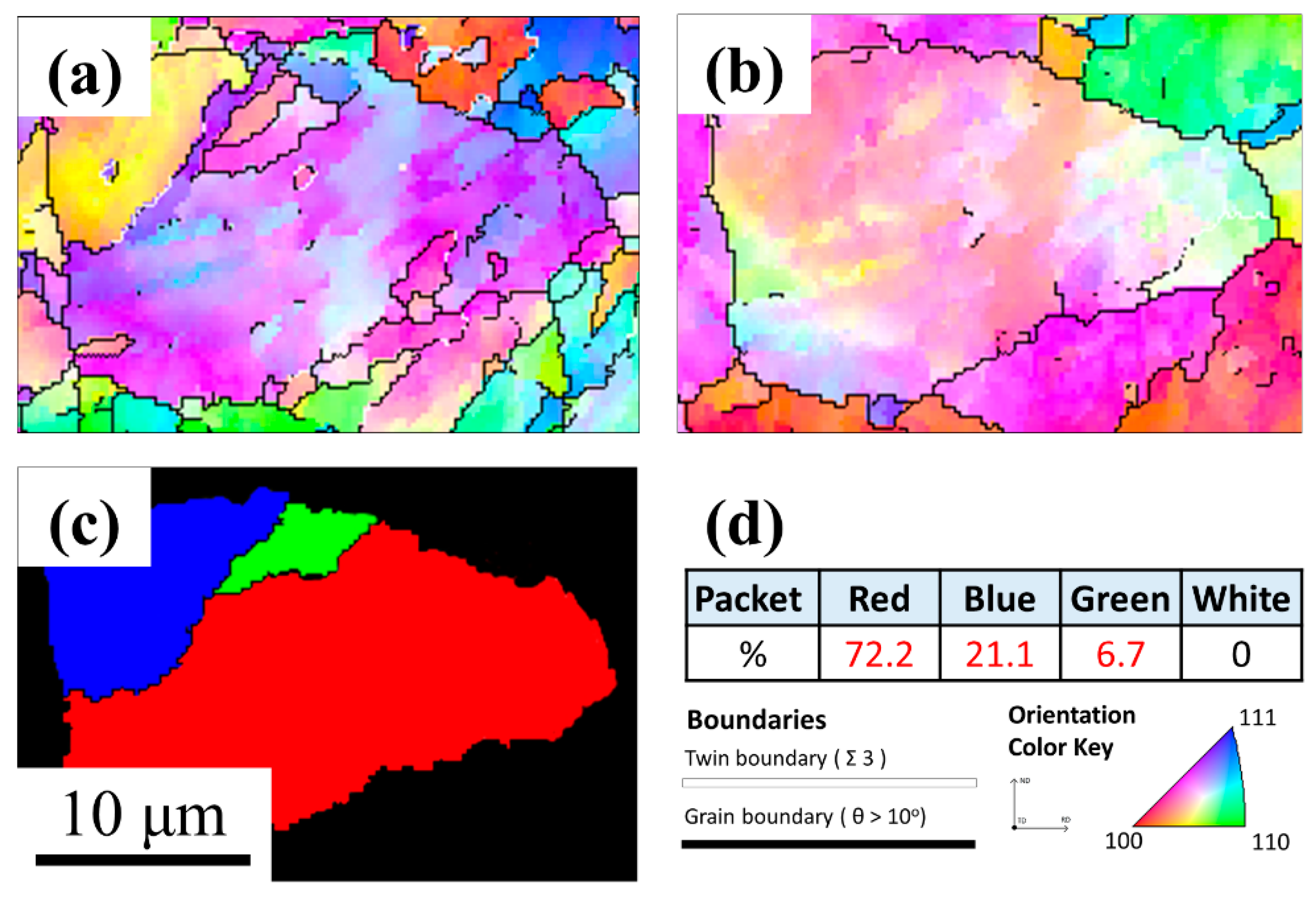
Figure 3 shows a comparison between the previous protocol and the new protocol in the reconstruction of ausformed austenite, as seen in Figure 3a. As shown in Figure 3b, there are many tiny austenite islands, which are incorrect reconstructions. They are prevented by the synergetic effects from boundary voting and solution tuning in the new protocol, as shown in Figure 3c. However, some incorrect or uncertain reconstructions are still observed, even in the new method. In this work, these grains will be manually skipped in statistical analyses. In all of our tests, the new protocol shows better quality in reconstructed results for both ausformed and non-ausformed austenite. However, its reconstruction speed is much lower because of boundary voting.

3. Results

3.1. Effect of Prior Austenite Grain Size

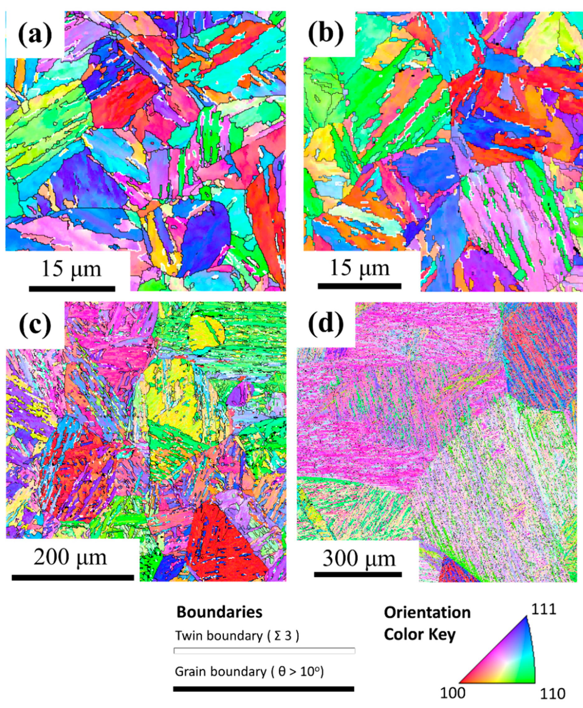
After the austenization at different temperatures, the experimental results were summarized and are presented in Figure 4. The typical structure of fully lath martensite could be seen in each condition, and there was no strong texture of martensite. It should be noted that the phase fraction of the retained austenite was less than 5%, which could be neglected in the current study.
To obtain further crystallography information, the method of parent phase reconstruction was applied to these martensitic raw data of EBSD. The results are shown in Figure 5. Equiaxed austenite grains with annealing twins were found in each condition. The prior austenite grain size could be determined by the line intersection method. As expected, higher austenization temperatures led to larger prior austenite grains, as shown in Table 2, and the corresponding harnesses were also measured. It should be noted that the grain size at 1280 °C was too large to be determined precisely.
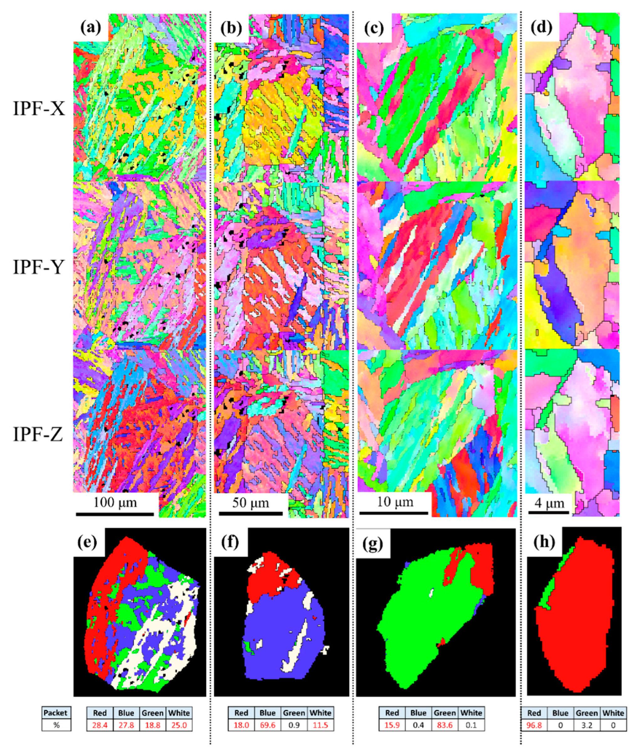
To show the distribution of the variants, the variants in the same packet were marked with the same color, e.g., V1–V6 in red, V7–V12 in blue, and so on. It should be noted that the four packets in the austenite have the same equivalence, and different choices of initial austenite orientation may lead to different packet colors (but they are equivalent). In this work, since the number of packets in a reconstructed grain could vary, we categorized the distribution of variants into four types: four-packet, three-packet, two-packet and one-packet dominant grains. Examples of each type are shown in Figure 6. Considering the noise and mis-indexed variants, packets with fractions < 5% were recognized as minor packets and not categorized as dominant packets.
Here, 130 reconstructed non-deformed grains were collected and analyzed to determine their numbers of dominant packets. The collected prior austenite grain sizes ranged from 4 μm to more than 300 μm. It should be mentioned that the grains from the 1280 °C condition were so large that their grain size could not be calculated precisely.
The distributions of sub-blocks (variants) in the packets were also examined in a similar way. However, the variants in one packet had a more complex relationship with one another than those in the two-packet relationship, with two examples being the Bain orientation in V1 and V4 or the twinning relationship in V1 and V2. To analyze these differences, the numbers of each variant should be added up instead of simply showing “n-variants dominant”. As a result, all of the variants were transformed into V1 to V6 equivalent variants, and the variant that covered the largest area was assigned as “V1”. Otherwise, the fluctuation of variants would be canceled out. In the end, 170 packets from different austenization temperatures were calculated, and the statistical results are presented in the discussion.

3.2. Effects of Ausforming

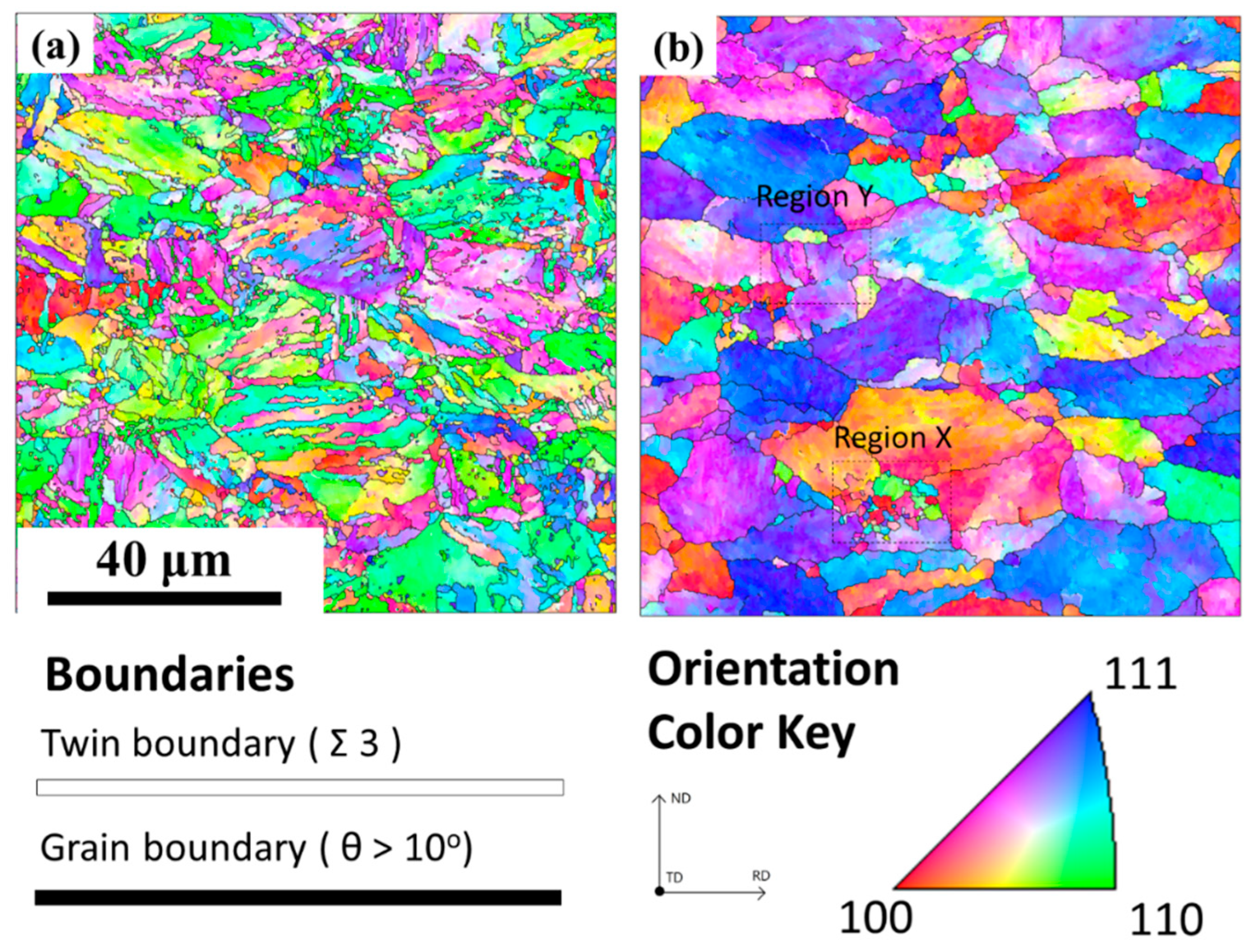
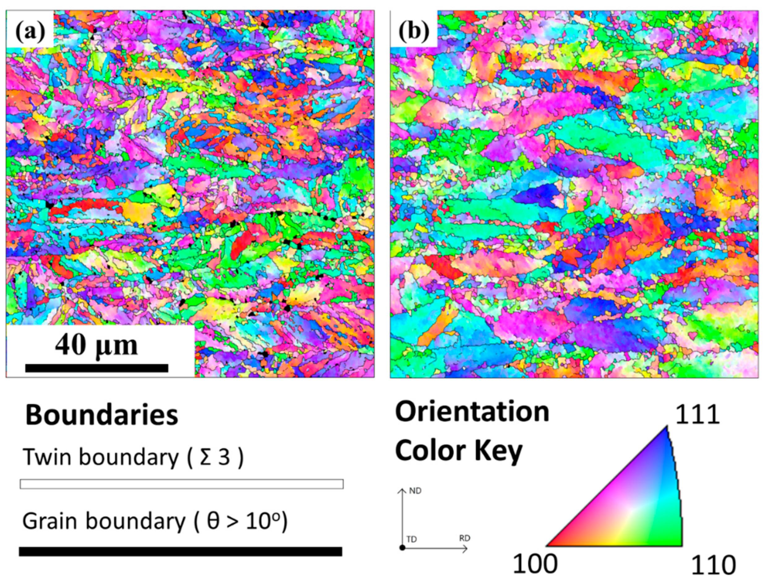
The EBSD analysis results of sample A and sample B are displayed in Figure 7a and Figure 8a. The reconstruction results for sample A and sample B are shown in Figure 7b and Figure 8b. As one can see, most of the austenite had transformed into martensite in both conditions. The reconstruction results showed that the grain shape of the deformed austenite was pancake-like. As the level of applied deformation increased, the austenite was further flattened. The orientation gradient in the deformed austenite grain was also remarkable.
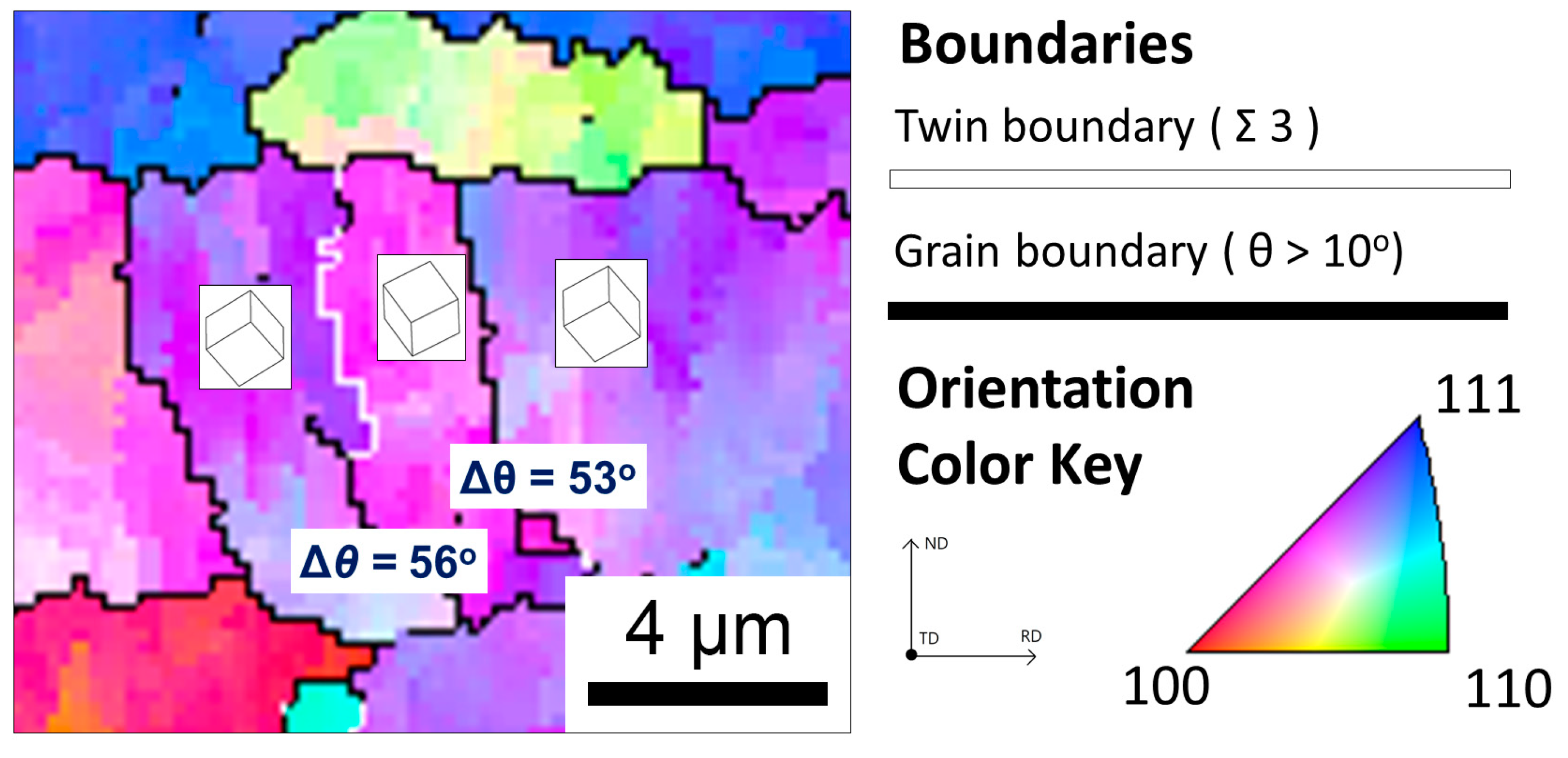
Some microstructures could be elucidated in the reconstruction results. As shown in Figure 7b, the small region X contained many little island-like austenite grains enclosed by high-angle grain boundaries. They might have resulted from severe deformation or recrystallization during the hot rolling. The other small region, Y, was likely twinning austenite before deformation. After hot rolling, the twinning plane collapsed and was distorted. Evidence in Figure 9 indicates that the crystal morphologies of the left and right ones were very similar, and the deviation angles between these grains were 56° and 53°, which were very close to the twinning relationship 1   1   1   60 ° .
The deformed structure was also examined with a similar procedure to show the distribution of the variants. As shown in Figure 10, an ausformed martensite region from sample A was reconstructed and then variant analysis was applied. In total, 80 grains were chosen from a non-deformed sample, sample A (30%), and sample B (50%) and calculated in the same way. In addition, the distribution of sub-blocks in the 80 packets was analyzed to show the tendency. All of the results are summed up in the next section.

4. Discussion

4.1. Effect of Prior Austenite Grain Size on Variant Distribution

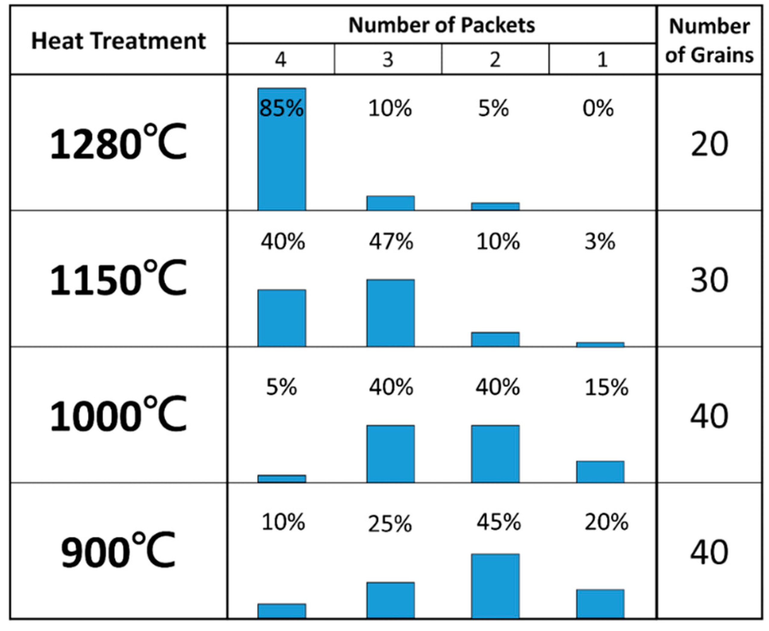
To demonstrate the tendency of distribution, we divided the grain sizes into four groups. The results are shown in Figure 11. In the 1280 °C group, it was obvious that one could find nearly all four packets in each grain with a grain size larger than 300 μm. However, in the 1150 °C group, there were two types, namely, four-packet and three-packet dominant grains. The grains tended to share fewer variants to complete the martensitic transformation. In the 1000 °C group, the grains were dominated by three- and two-packet types. In this range, the grain size was smaller than 40 μm. Finally, the 900 °C group was dominated by two-packet grains and had small fractions of three- and one-packet types.
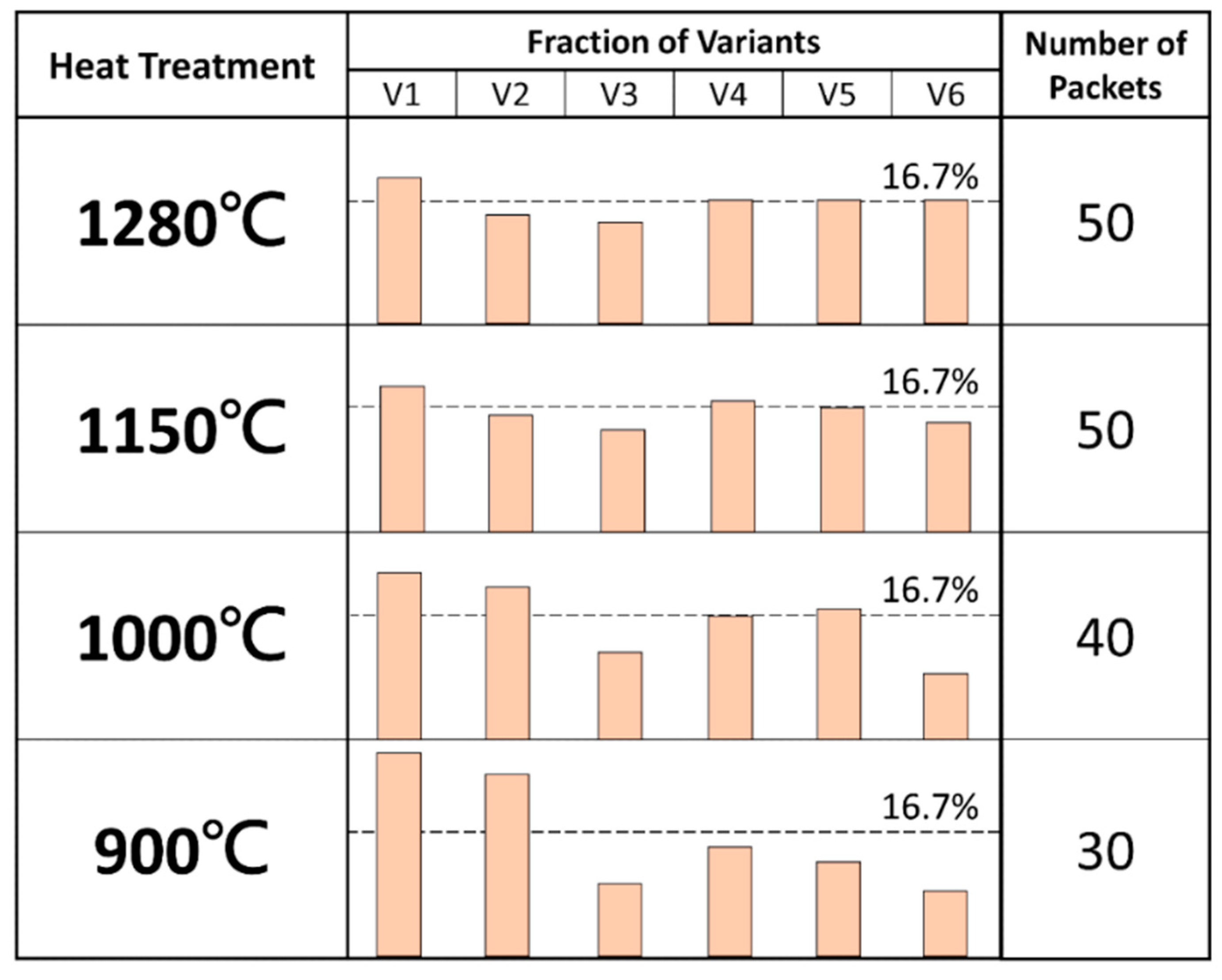
As for the distribution of the sub-blocks in one packet, the results are shown in Figure 12. When the prior grain size was large, the six variants tended to share the same frequency. As the grain size became finer, the fractions of V1 and V2 increased. Finally, in the 900 °C condition, with an average grain size of 15.2 μm, the fraction of V1 reached 28%, and that of V2, 25%, which were much larger than those of the other four variants.
The trend shown above could lead to the conclusion that the number of packets appearing in the grains would decrease as the corresponding grain size became finer. This phenomenon might result from the nature of martensitic transformation: the transformation starts from the prior austenite grain boundaries, and only one habit plane participates at first and forms the first packet. The interfaces between martensite and austenite act as the new nucleation sites to form other packets in different habit planes from the non-transformed region. However, if the grain size is so small that the remaining space is not sufficient for another packet to form or the size of the newly formed packet is too small, the resulting martensite might contain the variants from only a few packets.
As for the trend toward variant selection on the packet scale, the results showed that only V1 and V2, which had a twinning relationship to each other, would dominate in one packet. This dominance might also have resulted from the formation process of martensite. When the first packet with one Bain orientation formed, another variant with a twinning relationship from another Bain orientation would be produced simultaneously to compensate for the strain, known as self-accommodation [34]. Under normal conditions, all six variants would participate in a packet to compensate for the strain as much as possible. However, when the finer grain size constrained the packet size, only the variants that could compensate for the largest strain tended to form at first, and the other variants would be absent due to the insufficient residual space. As a result, only a pair of twinned variants dominated the prior austenite grain when the grain sizes were sufficiently fine.

4.2. Effect of Ausforming Level on Variant Distribution

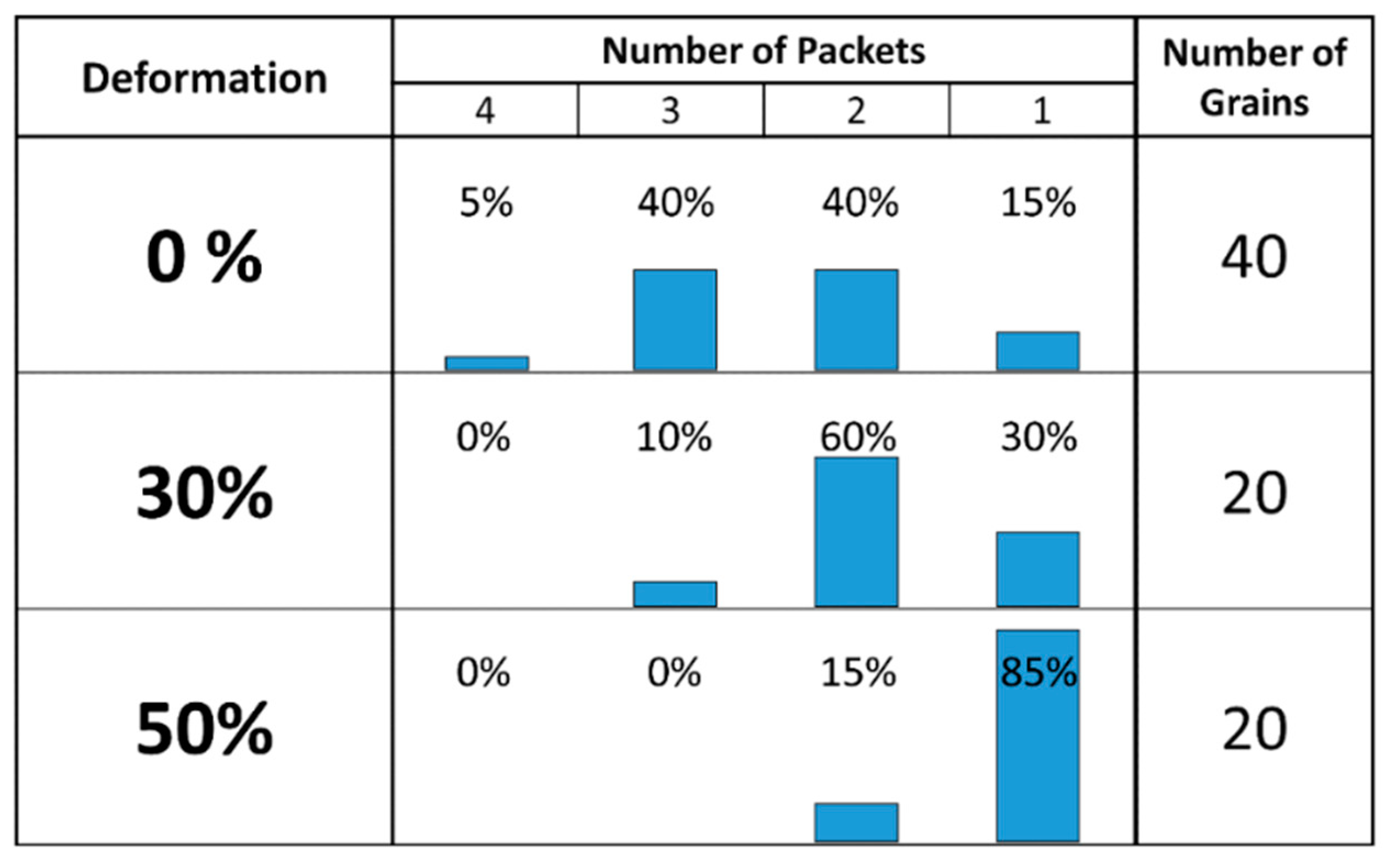
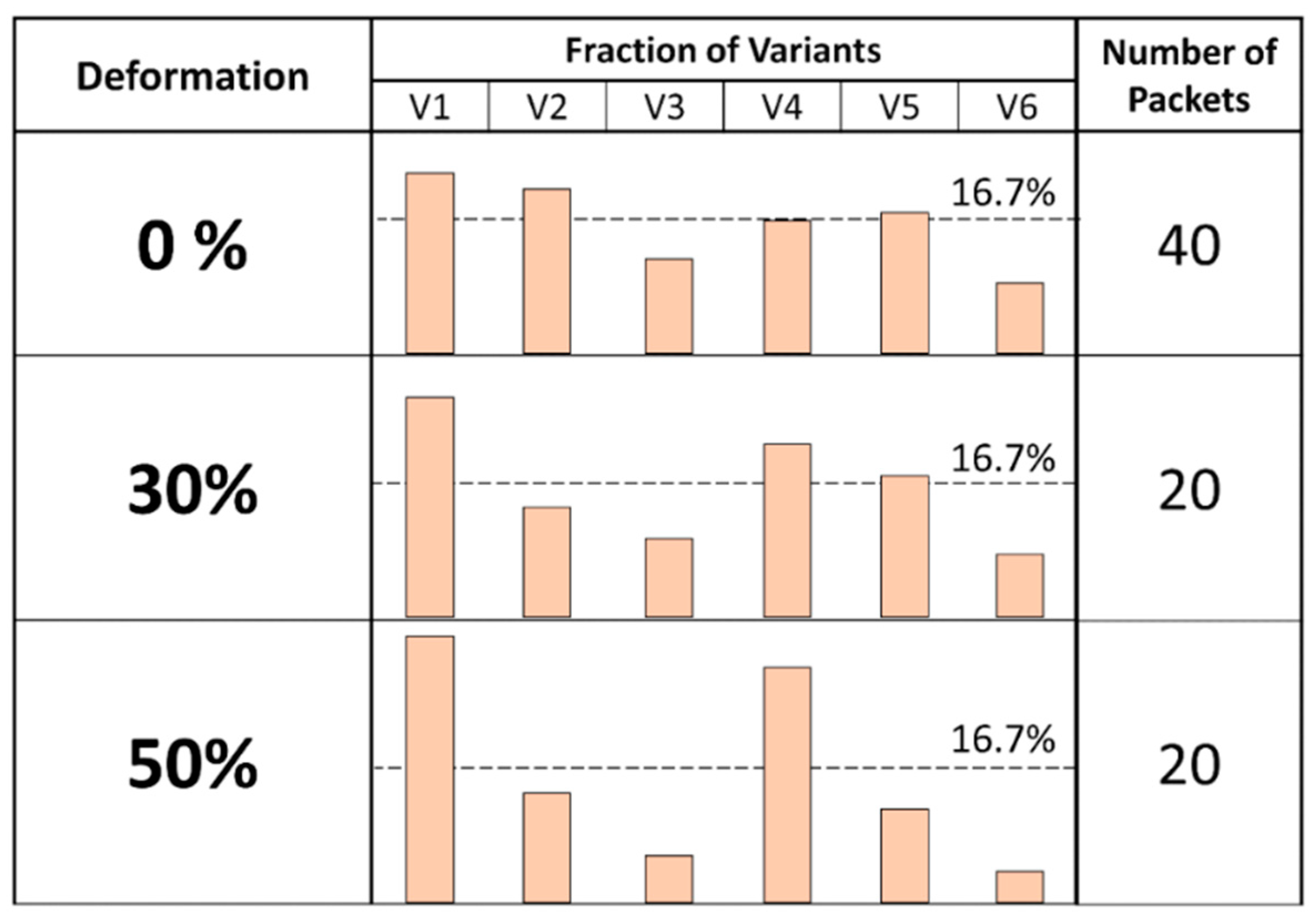
The analyzed results of the variant selection of the deformed structure are shown in Figure 13 and Figure 14. As shown in Figure 13, the distribution of the packets in the non-deformed structure was the same as that for the 1000 °C condition in Figure 11, which was two- or three-packet dominant. As the applied strain increased, only one packet was dominant in a prior austenite grain. This result is very similar to those of another study [15]. As for the distribution of sub-blocks, the results in Figure 14 show that two kinds of Bain orientation were dominant in non-deformed structures. However, in the 50% deformation condition, only V1 and V4, which were from the same Bain orientation, tended to form. A very strong variant selection phenomenon could be seen in the deformed structure.
The above results can be explained by the interaction between the slip bands and habit planes. The severe deformation would lead to dislocation sliding on the 1   1   1 plane of austenite. The habit plane of martensite is the 5   5   7 plane, which is very close to that of austenite, the 1   1   1 plane. The accumulated microbands on the 1   1   1 plane would act as nucleation sites of the martensite, which had a similar orientation to the habit plane [17]. As a result, specific variants would form at the beginning of the martensite transformation. For example, V1 and V4, having the same Bain orientation, would tend to form from this microband on the austenite 1   1   1 plane. Since these variants came from the same packet, they only led to one-packet dominance. Other packets would only form when the residual non-transformed space accumulated tangled dislocations and huge strain, which provided new nucleation sites for the other packets. The self-accommodation phenomenon in the deformed structure was not very obvious because the prior austenite grain had sufficient strain.
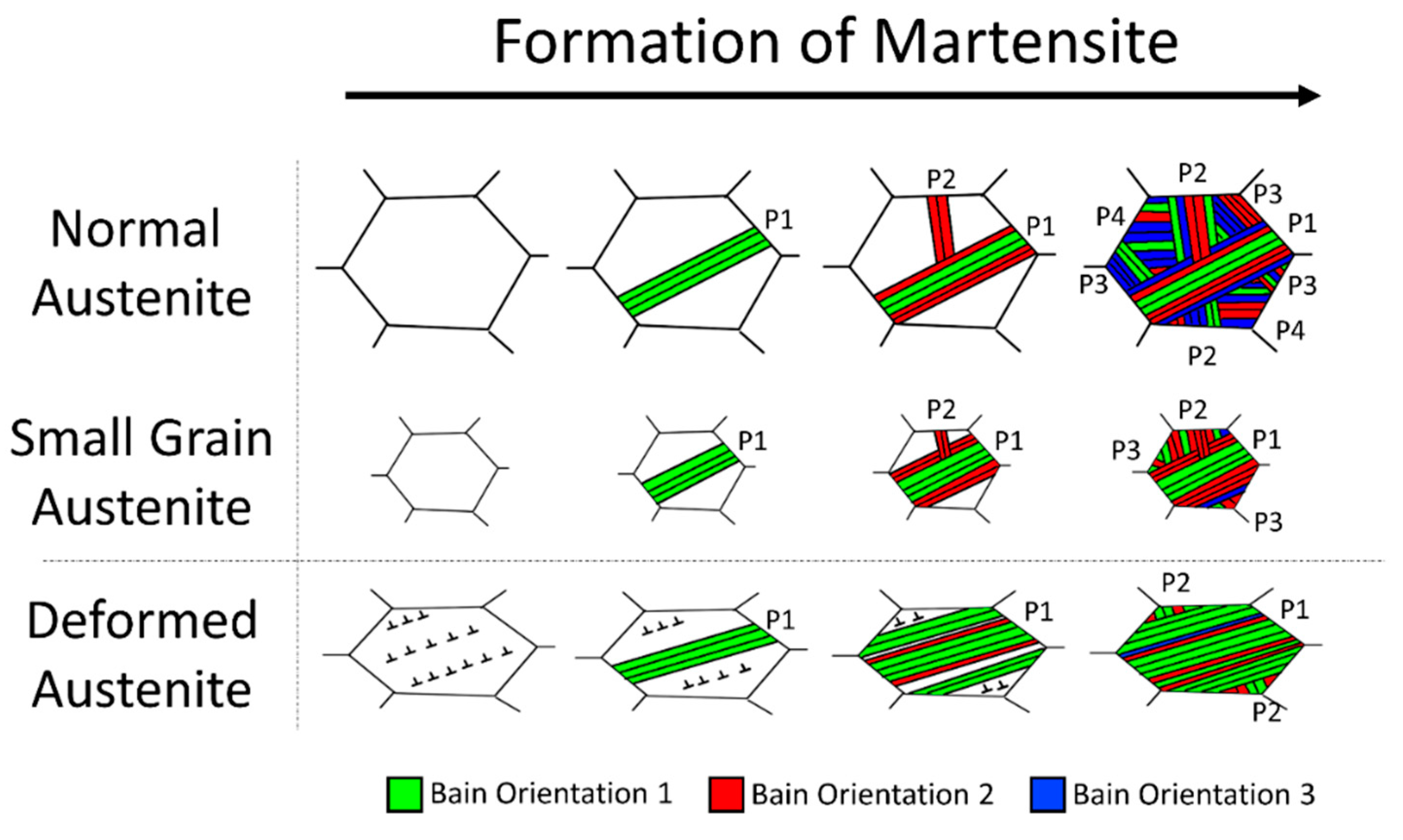
A schematic illustration showing the general results of this study is presented in Figure 15. The grain size of the prior austenite grains affects the number of packets that form after martensitic transformation and also the selection of variants with the twinning relationship. This is explained by the spatial restriction effect, in which the space of austenite grains will be occupied early by the initial packets when grain size is fine [35,36]. This makes the accommodation of transformation strain difficult and eventually suppresses martensitic transformation. Based on this study, a packet of twinned variants is a critical unit at the early stage of transformation. On the other hand, applied deformation may influence the variant selection phenomenon such that only one packet with one Bain orientation (e.g., V1 and V4) tends to occur. Under this circumstance, the transformation strain and applied deformation are mutually accommodated [17,36]. Therefore, variant selection is driven by plastic deformation.

5. Conclusions

In this work, we have revisited the effects of austenite grain size and ausforming on the variant selection of martensite transformation in Custom 475 maraging steel. A newly developed protocol was used to provide statistical analyses on this phenomenon based a large number of austenite grains. Several important points are listed below:
  • The new protocol, modified with boundary voting and solution tuning, greatly improved the quality of the reconstruction.
  • Fewer packets tend to form when the grain size of prior austenite is finer, or when large deformation is applied to the austenite.
  • When the grain size of the prior austenite is very fine (<20 μm), twinning sub-blocks (e.g., V1 and V2) tend to form at first to compensate for the strain. The insufficient space left by the early transformed martensite causes these two variants to dominate.
  • When the applied strain is large (≥50%), the accumulated microbands on the 1   1   1 planes act as nucleation sites, at which only variants from the same Bain orientation (e.g., V1 and V4) tend to form.
This work contributes to the understanding of the transformation and microstructure of lath martensite in steels through austenite engineering.

Author Contributions

Conceptualization, C.-Y.H. and H.-W.Y.; methodology, C.-Y.H. and S.-L.L.; software, C.-Y.H.; writing—original draft preparation, C.-Y.H.; writing—review and editing, H.-W.Y.; supervision, H.-W.Y.; funding acquisition, H.-W.Y. All authors have read and agreed to the published version of the manuscript.

Funding

This work was financially supported by the National Science and Technology Council (NSTC) in Taiwan (NSTC 109-2224-E-002-002 and NSTC 109-2628-E-002-009-MY3). This article was subsidized for English editing by National Taiwan University under the Excellence Improvement Program for Doctoral Students (grant number 108-2926-I-002-002-MY4), sponsored by the Ministry of Science and Technology, Taiwan.

Institutional Review Board Statement

Not applicable.

Informed Consent Statement

Not applicable.

Data Availability Statement

Data are available upon request.

Acknowledgments

The authors appreciate Delphic Chen from China Steel Corporation (Kaohsiung, Taiwan) for related discussion on reconstruction algorithm.

Conflicts of Interest

The authors declare no conflict of interest.

References

  1. Bhadeshia, H.K.D.H.; Honeycombe, S.R. 3-The Iron-Carbon Equilibrium Diagram and Plain Carbon Steels. In Steels, 3rd ed.; Butterworth-Heinemann: Oxford, UK, 2006; pp. 39–70. [Google Scholar]
  2. Nambu, S.; Shibuta, N.; Ojima, M.; Inoue, J.; Koseki, T.; Bhadeshia, H.K.D.H. In situ observations and crystallographic analysis of martensitic transformation in steel. Acta Mater. 2013, 61, 4831–4839. [Google Scholar] [CrossRef]
  3. Kitahara, H.; Ueji, R.; Tsuji, N.; Minamino, Y. Crystallographic features of lath martensite in low-carbon steel. Acta Mater. 2006, 54, 1279–1288. [Google Scholar] [CrossRef]
  4. Ray, R.K.; Jonas, J.J. Transformation textures in steels. Int. Mater. Rev. 1990, 35, 1–36. [Google Scholar] [CrossRef]
  5. Krauss, G. Martensite in steel: Strength and structure. Mater. Sci. Eng. A 1999, 273, 40–57. [Google Scholar] [CrossRef]
  6. Morito, S.; Yoshida, H.; Maki, T.; Huang, X. Effect of block size on the strength of lath martensite in low carbon steels. Mater. Sci. Eng. A 2006, 438, 237–240. [Google Scholar] [CrossRef]
  7. Wang, C.; Wang, M.; Shi, J.; Hui, W.; Dong, H. Effect of microstructural refinement on the toughness of low carbon martensitic steel. Scr. Mater. 2008, 58, 492–495. [Google Scholar] [CrossRef]
  8. Kimura, Y.; Inoue, T.; Yin, F.; Tsuzaki, K. Inverse Temperature Dependence of Toughness in an Ultrafine Grain-Structure Steel. Science 2008, 320, 1057–1060. [Google Scholar] [CrossRef]
  9. Yen, H.-W.; Chiang, M.-H.; Lin, Y.-C.; Chen, D.; Huang, C.-Y.; Lin, H.-C. High-Temperature Tempered Martensite Embrittlement in Quenched-and-Tempered Offshore Steels. Metals 2017, 7, 253. [Google Scholar] [CrossRef]
  10. Tsay, L.W.; Lu, H.L.; Chen, C. The effect of grain size and aging on hydrogen embrittlement of a maraging steel. Corros. Sci. 2008, 50, 2506–2511. [Google Scholar] [CrossRef]
  11. Galindo-Nava, E.I.; Rivera-Díaz-del-Castillo, P.E.J. A model for the microstructure behaviour and strength evolution in lath martensite. Acta Mater. 2015, 98, 81–93. [Google Scholar] [CrossRef] [Green Version]
  12. Lin, Y.-T.; Yi, H.L.; Chang, Z.Y.; Lin, H.-C.; Yen, H.-W. Role of Vanadium Carbide in Hydrogen Embrittlement of Press-Hardening Steels: Strategy from 1500 MPa to 2000 MPa. Front. Mater. 2020, 7, 432. [Google Scholar]
  13. He, Y.L.; Godet, S.; Jacques, P.J.; Jonas, J.J. Variant selection during the transformation of deformed austenite in a niobium bearing TRIP steel. In Icotom 14: Textures of Materials, Pts 1 and 2; Houtte, P.V., Kestens, L., Eds.; Trans Tech Publications Ltd: Zurich-Uetikon, Switzerland, 2005; Volume 495–497, pp. 345–350. [Google Scholar]
  14. Nakada, N.; Tsuchiyama, T.; Takaki, S.; Hashizume, S. Variant selection of reversed austenite in lath martensite. ISIJ Int. 2007, 47, 1527–1532. [Google Scholar] [CrossRef]
  15. Malet, L.; Barnett, M.R.; Jacques, P.J.; Godet, S. Variant selection during the gamma-to-alpha(b) phase transformation in hot-rolled bainitic TRIP-aided steels. Scr. Mater. 2009, 61, 520–523. [Google Scholar] [CrossRef]
  16. Miyamoto, G.; Iwata, N.; Takayama, N.; Furuhara, T. Mapping the parent austenite orientation reconstructed from the orientation of martensite by EBSD and its application to ausformed martensite. Acta Mater. 2010, 58, 6393–6403. [Google Scholar] [CrossRef]
  17. Miyamoto, G.; Iwata, N.; Takayama, N.; Furuhara, T. Quantitative analysis of variant selection in ausformed lath martensite. Acta Mater. 2012, 60, 1139–1148. [Google Scholar] [CrossRef]
  18. Miyamoto, G.; Iwata, N.; Takayama, N.; Furuhara, T. Variant selection of lath martensite and bainite transformation in low carbon steel by ausforming. J. Alloys Compd. 2013, 577, S528–S532. [Google Scholar] [CrossRef]
  19. Chiba, T.; Miyamoto, G.; Furuhara, T. Comparison of Variant Selection between Lenticular and Lath Martensite Transformed from Deformed Austenite. ISIJ Int. 2013, 53, 915–919. [Google Scholar] [CrossRef]
  20. He, J.G.; Du, J.; Zhang, W.Z.; Zhang, C.; Yang, Z.G.; Chen, H. Abnormal Anisotropic Dilatation During Bainitic Transformation of Ausformed Austenite. Metall. Mater. Trans. A Phys. Metall. Mater. Sci. 2019, 50, 540–546. [Google Scholar] [CrossRef]
  21. Ueda, M.; Yasuda, H.Y.; Umakoshi, Y. Controlling factor for nucleation of martensite at grain boundary in Fe-Ni bicrystals. Acta Mater. 2003, 51, 1007–1017. [Google Scholar] [CrossRef]
  22. Jafarian, H.; Borhani, E.; Shibata, A.; Tsuji, N. Variant selection of martensite transformation from ultrafine-grained austenite in Fe–Ni–C alloy. J. Alloys Compd. 2013, 577, S668–S672. [Google Scholar] [CrossRef]
  23. Yen, H.-W.; Ooi, S.W.; Eizadjou, M.; Breen, A.; Huang, C.-Y.; Bhadeshia, H.K.D.H.B.; Ringer, S.P. Role of stress-assisted martensite in the design of strong ultrafine-grained duplex steels. Acta Mater. 2015, 82, 100–114. [Google Scholar] [CrossRef] [Green Version]
  24. Humbert, M.; Gey, N. The calculation of a parent grain orientation from inherited variants for approximate (b.c.c.-h.c.p.) orientation relations. J. Appl. Crystallogr. 2002, 35, 401–405. [Google Scholar] [CrossRef]
  25. Cayron, C.; Artaud, B.; Briottet, L. Reconstruction of parent grains from EBSD data. Mater. Charact. 2006, 57, 386–401. [Google Scholar] [CrossRef]
  26. Cayron, C.; Barcelo, F.; de Carlan, Y. The mechanisms of the fcc-bcc martensitic transformation revealed by pole figures. Acta Mater. 2010, 58, 1395–1402. [Google Scholar] [CrossRef]
  27. Suikkanen, P.P.; Cayron, C.; DeArdo, A.J.; Karjalainen, L.P. Crystallographic Analysis of Martensite in 0.2C-2.0Mn-1.5Si-0.6Cr Steel using EBSD. J. Mater. Sci. Technol. 2011, 27, 920–930. [Google Scholar] [CrossRef]
  28. Germain, L.; Gey, N.; Mercier, R.; Blaineau, P.; Humbert, M. An advanced approach to reconstructing parent orientation maps in the case of approximate orientation relations: Application to steels. Acta Mater. 2012, 60, 4551–4562. [Google Scholar] [CrossRef]
  29. Blaineau, P.; Germain, L.; Humbert, M.; Gey, N. A New Approach to Calculate the γ Orientation Maps in Steels. Solid State Phenomena 2010, 160, 203–210. [Google Scholar] [CrossRef]
  30. Miyamoto, G.; Takayama, N.; Furuhara, T. Accurate measurement of the orientation relationship of lath martensite and bainite by electron backscatter diffraction analysis. Scr. Mater. 2009, 60, 1113–1116. [Google Scholar] [CrossRef]
  31. Carpenter Technology Corporation. Available online: https://www.carpentertechnology.com/ (accessed on 1 September 2022).
  32. Huang, C.-Y.; Yen, H.-W. HRTEM investigations on nano precipitates in Custom 475 maraging stainless steel. Mater. Charact. 2021, 178, 111216. [Google Scholar] [CrossRef]
  33. Huang, C.-Y.; Ni, H.-C.; Yen, H.-W. New protocol for orientation reconstruction from martensite to austenite in steels. Materialia 2020, 9, 100554. [Google Scholar] [CrossRef]
  34. Zhang, S.Y.; Morito, S.; Komizo, Y. Variant Selection of Low Carbon High Alloy Steel in an Austenite Grain during Martensite Transformation. ISIJ Int. 2012, 52, 510–515. [Google Scholar] [CrossRef] [Green Version]
  35. Takaki, S.; Fukunaga, K.; Syarif, J.; Tsuchiyama, T. Effect of Grain Refinement on Thermal Stability of Metastable Austenitic Steel. Mater. Trans. 2004, 45, 2245–2251. [Google Scholar] [CrossRef]
  36. Matsuoka, Y.; Iwasaki, T.; Nakada, N.; Tsuchiyama, T.; Takaki, S. Effect of Grain Size on Thermal and Mechanical Stability of Austenite in Metastable Austenitic Stainless Steel. ISIJ Int. 2013, 53, 1224–1230. [Google Scholar] [CrossRef] [Green Version]
Figure 1. Process of heat treatment for examination of the variant selection phenomena of (a) different grain sizes and (b) deformed structures.
Metals 12 01511 g001
Figure 2. (a) Schematic diagram showing boundary voting along the boundary of Group A; (b) the effect of solution tuning. Different colors schematically indicate different orientations.
Metals 12 01511 g002
Figure 3. Comparison between the previous protocol and the new protocol in the reconstruction of ausformed austenite: (a) the raw IPF-Z of martensite; (b) the IPF-Z of austenite reconstructed by the previous protocol; and (c) the IPF-Z of austenite reconstructed by the new protocol. Same scale for three figure panels.
Metals 12 01511 g003
Figure 4. EBSD analysis results after applying different austenization temperatures. The IPF-Z of martensite showed the orientation distribution and lath morphology of (a) 900 °C; (b) 1000 °C; (c) 1150 °C; and (d) 1280 °C conditions. The boundaries were not applied to (d) to avoid too many lines of boundaries.
Metals 12 01511 g004
Figure 5. Results of austenite reconstruction from the raw data of EBSD in Figure 4. The IPF-Z of austenite showed the orientation distribution and grain morphology of the (a) 900 °C; (b) 1000 °C; (c) 1150 °C; and (d) 1280 °C conditions.
Metals 12 01511 g005
Figure 6. Examples of non-deformed reconstructed grains with different numbers of dominant packets. (ad) The IPF-X, IPF-Y and IPF-Z raw data of martensite from coarse to fine prior austenite grains; (eh) the reconstruction results of packet distribution from coarse to fine prior austenite grains. Red, blue, green and white represent different packets instead of orientation.
Metals 12 01511 g006
Figure 7. EBSD analysis results of sample A (30% deformed): (a) the IPF-Z showing the orientation of martensite; and (b) the IPF-Z showing the reconstructed orientation of austenite.
Metals 12 01511 g007
Figure 8. EBSD analysis results of sample B (50% deformed): (a) the IPF-Z showing the orientation of martensite; and (b) the IPF-Z showing the reconstructed orientation of austenite.
Metals 12 01511 g008
Figure 9. Region cropped from Figure 6b, region Y, to show the collapse of the twinning plane in the reconstruction results.
Metals 12 01511 g009
Figure 10. Example of the deformed reconstructed grain from sample A. (a) The IPF-Z raw data of martensite; (b) the reconstructed results of (a); (c) the reconstructed results of packet distribution. Red, blue and green represent different packets instead of orientation; and (d) the distribution numbers of packets in this grain.
Metals 12 01511 g010
Figure 11. Statistical bar charts showing the numbers of dominant packets under the four heat treatment conditions. The 1280 °C group was only dominated by four packets, and the 1150 °C, 1000 °C and 900 °C groups were dominated by the distribution of two or three distinct types of packets.
Metals 12 01511 g011
Figure 12. Statistical bar chart showing the fraction of each variant in one packet under four conditions of heat treatment. The 1280 °C group had equal fractions from V1 to V6, while the 900 °C condition was dominated by V1 and V2.
Metals 12 01511 g012
Figure 13. Statistical bar charts showing the numbers of dominant packets under different levels of deformation. The non-deformed group was dominated by two or three packets, while the 50% condition was dominated by only one packet.
Metals 12 01511 g013
Figure 14. Statistical bar charts showing the fractions of each variant in one packet under different levels of deformation. The 50% deformed condition was dominated by V1 and V4.
Metals 12 01511 g014
Figure 15. Schematic diagram summarizing the formation of martensite under different heat treatment conditions of austenite. It is noted that different packets are presented in different parallelisms.
Metals 12 01511 g015
Table 1. Chemical composition of Custom 475.
ElementCNiCrCoMoAlMnSPFe
wt.%<0.028.011.08.55.01.25<0.5<0.5<0.02Bal.
Table 2. Prior austenite grain sizes and corresponding hardness under four different austenization temperatures.
ConditionAs-Received900 °C1000 °C1150 °C1280 °C
Grain size (μm)-15.220.7115.8>300
Hardness (HV)246352 ± 8333 ± 20262 ± 25251 ± 19
Publisher’s Note: MDPI stays neutral with regard to jurisdictional claims in published maps and institutional affiliations.