Abstract
Thermal stability is one of the most basic high-temperature performance indices of hot die steel. It directly determines whether the mold can maintain good surface hardness, dimensional stability and material failure resistance for a long time under high temperature and high pressure, and then affect the service life of the material. In this paper, the effect of Si on the thermal stability of 4Cr3Mo2V hot-work die steel was studied. Scanning electron microscopy (SEM) and transmission electron microscopy (TEM) techniques were used to characterize the microstructure evolution. Thermodynamic analyses were carried out in combination with Thermo-Calc software to explore the mechanism affecting thermal stability. The results show that the thermal stability of the 1.0% Si-containing steel (referred to as 1.0 Si steel) sample exceeded that of the 0.3% Si-containing steel (referred to as 0.3 Si steel) sample. After tempering at 650 °C for 64 h, the matrices of the two tested steel samples mainly comprised large-sized M6C carbides. Additionally, the carbides in the 0.3 Si steel sample showed obvious aggregation growth, and a small number of round-like M23C6 carbides appeared, which decreased the hardness in the later stage of tempering. The average particle size of M6C in the 1.0 Si steel sample is 100–200 nm, the average particle size of M6C in the 0.3 Si steel sample is 100–400 nm, and 1.0 Si steel disperses and precipitates finer MC-type and M2C-type secondary carbides, so it has better thermal stability.
1. Introduction
4Cr3Mo2V hot-work die steel can be used to produce parts with complex shapes or obtain high dimensional accuracy, and can be used in dozens of industries, such as agricultural machinery, machine tools, electronics, national defense, computers, medical devices, clocks, cameras and daily hardware. However, high-temperature molten metal is injected into the mold at high speed when it is in service. In order to ensure the long-term use of the mold, the mold should have a high thermal strength at the working temperature. Die-casting dies produced continuously in large quantities should be kept at a high hardness for a long time under a certain temperature. Therefore, the mold should have good tempering stability. Thermal stability is one of the most basic high-temperature performance indices of hot-work die steel. It directly determines whether the tool and die can maintain good surface hardness, dimensional stability, and resistance to material failure for a long time under high temperature and high pressure, and affects the service life of the material. The in-service microstructure of die steel mainly comprises high-dislocation-density tempered martensite and alloying carbide precipitates. During high-temperature tempering and heat preservation, carbon and other alloying elements are continuously precipitated and diffused, which promotes the transformation of martensite to stable tempered martensite first. With the extension of the heat preservation time, the tempered martensite is further decomposed. Finally, it is transformed into a steady-state pearlite structure comprising a ferrite matrix and carbide [1,2]. The tempering softening and thermal fatigue resistance characteristics of hot-work die steel materials are closely related to the microstructural stability under high-temperature heat preservation [3,4]. The high-temperature stability mainly depends on two aspects: firstly, the recovery degree of tempered martensite with high dislocation density; secondly, the precipitation and growth of alloying carbide [5,6].
The non-carbide-forming element, Si, as one of the more common alloying elements, can prevent the diffusion of C atoms and inhibit the growth and coarsening of cementite to improve the high-temperature properties of materials. Firstly, Si greatly influences the retained austenite in steel. Previous studies have reported that Si can significantly improve the stability of the retained austenite by promoting the distribution of carbon from martensite to austenite so that the retained austenite does not decompose easily during-tempering [7,8,9,10]. As the Si content increases, the strengthening effect of the solid solution increases, and the tensile strength of the material gradually improves. Secondly, the increase in the retained austenite increases the elongation and obvious improvement in comprehensive properties [11]. However, Si affects the properties of steel by changing the behavior of the carbide. Kim et al. studied the Si effect on tempered martensite θ-phase precipitation and ε → θ. Under quasi-equilibrium conditions, Si reduces the driving force of cementite nucleation, Si atoms gather at the carbide–matrix interface, the flux of C atoms from the matrix into cementite reduces and the growth of cementite is delayed [12]. Zeng et al. also reported that during tempering and heat preservation of die-cast die steel SDYZ1, Ni, which is a non-carbide-forming element, similar to Si, is mainly distributed around the carbide, hindering the diffusion movement of C atoms and inhibiting the aggregation and growth of carbide [13]. Delagnes et al. [14] studied AISI H11 steel with Si contents of 0.35% and 0.92% and found that Si prevents cementite coarsening and promotes its dissolution, H11 steel with high Si content can form alloying carbides at a lower tempering temperature, thus advancing the secondary hardening peak. In contrast, low-Si-content steel contains fine vanadium carbides with a higher volume fraction and better thermal fatigue resistance. However, when Zhou et al. [15,16] studied AISI H13 steel with different Si contents, they found that the secondary carbides in the steel with higher Si content are smaller and have better thermal fatigue resistance, and Si improves the tempering activation energy and enhances the thermal stability of the material, which differs from the research results of scholars [14]. Therefore, this study aims to explore the thermal stability of 4Cr3Mo2V hot-work die steel with 0.3% and 1.0% Si and explore the effects of the difference in the Si content on the type, morphology, size and quantity of carbides during tempering and heat preservation using SEM and TEM techniques. The results herein provide relevant information for further development of the research field of high-temperature properties of die materials.
2. Materials and Methods
The testing materials were from the same batch of 0.3 Si and 1.0 Si steels prepared by the same equipment in a domestic special steel enterprise. Afterward, they underwent induction melting, electroslag remelting, forging, air cooling after forging and other processes. The chemical composition is presented in Table 1.

Table 1.
Chemical composition of tested steel (mass fraction/%).
First, the samples were placed in a YFX12-130-1 box-type resistance furnace, the temperature was set at 1030 °C for 45 min and then the samples were quenched in oil immediately. Then, the following tests were conducted: (1) Thermal stability test: After quenching, the samples were treated by four tempering processes. As shown in Figure 1, their hardness values were adjusted to 46 and 47 HRC. Afterwards, they were placed in an S2-5-12 box-type resistance furnace for heat preservation. Here, two temperatures were set (600 °C and 650 °C) and the stabilized times were 1, 2, 4, 8, 16, 24, 32, 48 and 64 h. (2) Tempering characteristic test: The quenched samples were tempered twice at 300, 400, 450, 480, 500, 520, 540, 560, 580, 600, 620 and 640 °C, and the tempering temperature was maintained for 2 h each time. The Rockwell hardness was measured by using a 69-1 hardness tester.
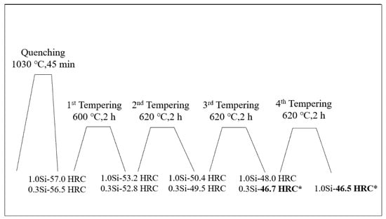
Figure 1.
Heat treatment process curve of tested steel with modulated hardnesses of 46–47 HRC. (The hardness of 0.3 Si steel reaches 46.7 HRC after tempering for three times at 600 °C, 620 °C and 620 °C for two hours each time, and the hardness of 1.0 Si steel reaches 46.5 HRC after tempering for four times at 600 °C, 620 °C, 620 °C and 620 °C for two hours each time).
After grinding and polishing, the samples were corroded with a 4% nitric acid alcohol solution. Furthermore, the microstructure was observed using optical microscopy (OM, Nikon MV 100) and field emission SEM (Zeiss Supra 40). The carbides in the samples were collected by carbon film replica technology. The size, morphology and distribution of the carbides were observed by using high-resolution field emission TEM (JEM-2010F). Furthermore, the types of carbides were determined by diffraction pattern calibration and energy spectrum analysis.
3. Results
3.1. Effects of Tempering Temperature and Time on Hardness
The thermal stability of steel indicates its ability to maintain its inner wall organization and mechanical properties in the process of heating and insulation at a certain temperature, which is one of the most important characteristics of hot-work die steel.
Figure 2 shows the thermal stability curve of the tested steel at 600 °C and 650 °C. During the two heat preservation processes, the hardness of the 1.0 Si steel sample exceeds that of the 0.3 Si steel sample. Further, the difference between the two hardness values at 650 °C exceeds that at 600 °C, indicating that the thermal stability advantage of the 1.0 Si steel sample is more significant at the higher heat preservation temperature. Within 0–16 h during the heat preservation stage of holding temperature at 650 °C, the hardness values of the 0.3 Si and 1.0 Si steel samples decreases by 16.7 and 14.5 HRC, respectively, mainly because the martensite recovery degree is relatively large in the early stage of tempering, the alloying elements in the martensite precipitate outward continuously and the matrix is seriously weakened. With the extension of the holding time, the decreasing trends of the hardness values of the two steel samples are gradual, and the hardness decreases by only 5.6 and 3.5 HRC, respectively, within 16–64 h. The results of comparing the change in hardness of the two tested steel samples indicate that the hardness difference between 1.0 Si and 0.3 Si steel samples in the early heat preservation stage is small. In addition, the 1.0 Si steel sample’s hardness is 2 HRC higher than that of the 0.3 Si steel sample. As the heat preservation time increases, the hardness difference between them gradually increases. After 64 h of heat preservation, the hardness values of the 0.3 Si and 1.0 Si steel samples are 24.4 and 28.5 HRC, respectively. The latter one is 4.1 HRC higher than the former one, and the 1.0 Si steel sample shows better thermal stability.
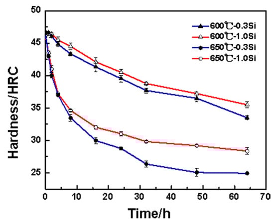
Figure 2.
Thermal stability curve of tested steels.
3.2. Effects of Tempering Temperature on Hardness
During quenching, a large number of alloy elements are dissolved in the matrix, and the martensite reaches the supersaturated state, leading to the appearance of high-density dislocations in the quenching structure. In order to obtain excellent strength and toughness, it is necessary to temper the experimental steel after quenching. The purpose of tempering is to completely transform the structure, decompose the residual austenite and eliminate the residue caused by hardening stress. Excellent strength and toughness are obtained. Tempering at different temperatures results in various types of carbide precipitation in the steel matrix, which causes the steel to obtain different hardness values. Figure 3 shows the tempering characteristic curves of two tested steel samples after being quenched at 1030 °C and tempered twice at different tempering temperatures for 2 h each time. The secondary hardening peaks of the 0.3 Si and 1.0 Si steel samples appear near 520 °C and 500 °C, respectively. The increase in the Si content promotes the secondary hardening peak to move toward a lower temperature, indicating that during tempering, Si promotes the precipitation of carbides from the α-Fe crystal structures, resulting in the secondary hardening of 1.0 Si steel at a lower temperature, which is similar to the research results of Delagnes [14].
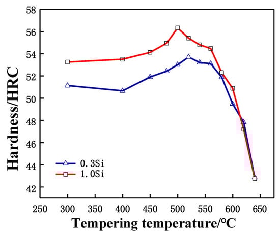
Figure 3.
Tempering characteristic curve of tested steels after quenching at 1030 °C.
3.3. Analysis of Microstructural Evolution Mechanism
Figure 4 presents the SEM image of the tested steel samples after being held at 650 °C for different lengths of times. At 0 h of the thermal stability test, that is, when the structure is in the quench-temper state (Figure 4a,b), the microstructures of the two tested steel samples are mainly tempered martensite and alloying carbide. After being held at 650 °C for 4 h (Figure 4c,d), the martensite in the two tested steel samples begins to recover and the number of carbide particles on the matrix increases. After being held at constant temperature for 16 h (Figure 4e,f), the martensite lath characteristics in the two tested steel samples are further weakened, and the carbides in the 0.3 Si steel sample are coarsened. After a holding time of 64 h (Figure 4g,h), the carbides in the structure of the 1.0 Si steel sample maintain a smaller size and still retain some martensitic lath characteristics. In contrast, most areas of the 0.3 Si steel sample matrix have recovered, with more large-sized carbides. The atomic radii of Si and α-Fe are 0.118 and 0.126 nm, respectively. The solid solution of Si causes lattice distortion of the ferrite, so it plays a role in solid solution strengthening. Furthermore, Si is soluble in ε-carbide, so its stability is improved, and then delayed transformation of ε → θ occurs [17]. During tempering, Si hinders the diffusion movement of C atoms. However, Kozeschnik et al. proposed that if the carbon content in the parent phase is oversaturated, the driving force of the atomic precipitation is large, and Si ineffectively prevents the precipitation of cementite [18]. The increase in Si content leads to the advancement of precipitation strengthening, which leads to the movement of the tempering secondary hardening peak of the 1.0 Si steel sample to a low temperature. It also shows that Si reduces the precipitation threshold of C atoms and promotes the precipitation of C atoms from the martensite matrix, but it hinders their diffusion and, thus, hinders the growth of the cementite. The change in the number and size of carbides during tempering can be explained as follows: in the early stage of tempering and heat preservation, compared with the 0.3 Si steel sample, a large number of carbides precipitate from the matrix of 1.0 Si steel sample. However, with the extension of the holding time, the carbides precipitated from the 1.0 Si steel sample still maintain a small size and do not grow significantly; hence, it effectively delays the downward trend of the hardness.
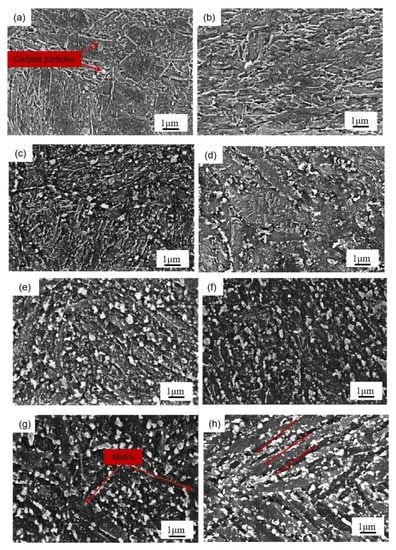
Figure 4.
SEM micrographs of tested steels at 650 °C after different holding times: (a) 0.3 Si—0 h, (c) 0.3 Si—4 h, (e) 0.3 Si—16 h, (g) 0.3 Si—64 h, (b) 1.0 Si—0 h, (d) 1.0 Si—4 h, (f) 1.0 Si—16 h, (h) 1.0 Si—64 h.
Figure 5 shows the carbon film replica TEM image of the tested steel samples after being held at 650 °C for 64 h. The carbides are mainly divided into two types: spherical or ellipsoidal large-sized secondary carbide particles, and small irregular-shaped secondary carbide particles [19]. Comparing Figure 5a,b, it is shown that the number of fine carbides in the 1.0 Si steel sample is higher and their particle size ranges from 1–80 nm. Thus, the secondary carbide at Mark 1 in Figure 5a is selected for light and dark field image observation, shooting pattern calibration, and energy spectrum analysis. It is determined that the MC/M2C carbide is rich in V, Mo and contains a small amount of Cr (Figure 6). The large-particle carbides at Mark 2 in Figure 5b are further analyzed by using diffraction pattern calibration and energy spectrum analysis (Figure 7). Evidently, there are Fe2Mo4C carbides with a crystal plane constant of [321]. It can be inferred that these kinds of large-particle spherical carbides are mainly M6C carbides rich in Mo and Fe. Some MC/M2C carbides in the tested steel samples are attached to the growth of large-particle M6C carbides, indicating that during the heat preservation process, C, Mo and other alloying elements in M6C gradually diffuse outward to form this part of the secondary carbides. The two types of the tested steel sample matrices are dominated by M6C carbide. The M6C carbide particle size range of the 0.3 Si steel sample ranges from 100 to 300 nm, and the carbide particles adhere, grow together and accumulate into clusters. The particle size of M6C carbide in the 1.0 Si steel sample ranges from 100–200 nm, with a small size and relatively dispersed distribution, indicating that Si effectively inhibits the aggregation and coarsening of this particular carbide in the later stage of the thermal stability test.
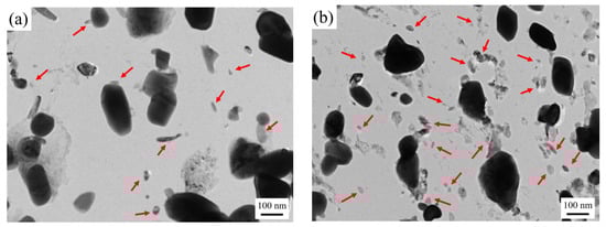
Figure 5.
TEM micrographs of carbon extraction replicas of tested steel after tempering for 64 h at 650 °C: (a) 0.3 Si; (b) 1.0 Si.
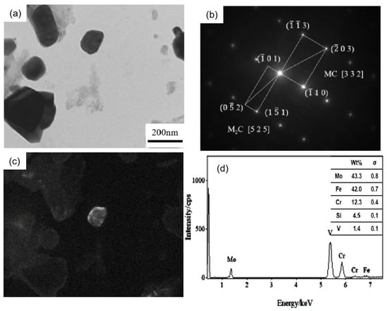
Figure 6.
TEM of MC/M2C carbide in 0.3 Si steel after tempering for 64 h at 650 °C: (a) bright field image of carbide; (b) SAED pattern; (c) corresponding dark field image; (d) EDS analysis.
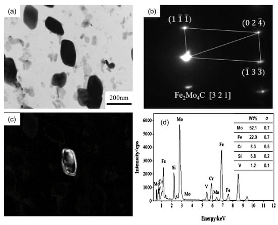
Figure 7.
TEM of M6C carbide in 1.0 Si steel after tempering for 64 h at 650 °C: (a) bright field image of carbide; (b) SAEDpattern; (c) corresponding dark field image; (d) EDS analysis.
Additionally, there are long rod-shaped carbides in the 0.3 Si steel sample (arrow in Figure 8a), with a particle radius size of 100–200 nm. After diffraction pattern calibration and energy spectrum analysis, it is determined that they are Cr-rich M23C6 carbides. These carbides have complex face-centered cubic structures and poor stability. They are easy to transform under high-temperature heat preservation for a long time, resulting in material softening. A previous study [20,21] reported that metastable Mo-rich M2C carbides have poor stability. During the long-term heat preservation process, some Cr atoms gradually diffuse into the M2C and combine with the C atoms to form Cr23C6 carbides by an in situ nucleation mechanism, which is one of the factors leading to the gradual decline in the hardness of the 0.3 Si steel sample.
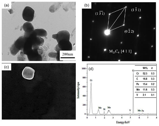
Figure 8.
TEM of M23C6 carbide in 0.3 Si steel after tempering for 64 h at 650 °C: (a) bright field image of carbide; (b) SAED pattern; (c) corresponding dark field image; (d) EDS analysis.
4. Discussion
4.1. Effects of Precipitates on Properties of Steel during Thermal Stabilization
Large carbides lead to the formation of initial cracks of materials, resulting in high-temperature cracking and other failure forms, and it is very important to measure and calculate the size and quantity of carbides. Figure 9 shows the carbide bright field image of the specimen magnified 8000 times under a transmission electron microscope after the thermal stability test at 650 °C for 64 h. Overall, the carbide particles in the 0.3 Si steel sample are coarse in size and aggregate and grow in clusters, whereas the carbides in the 1.0 Si steel sample are smaller in size and more dispersed. To obtain a more intuitive carbide situation, Image J Pro 6.0 software counts the size and number percentage of carbides, and an average particle size distribution diagram is developed (Figure 10). The carbide distribution of 1.0 Si steel is mainly concentrated in the size range of 1–150 nm, and the proportion of large-size carbides is small. The proportion of carbides of various sizes in 0.3 Si steel is evenly distributed, and the proportion of carbides with a size of 200–400 nm is still high. The size, percentage and type of carbides after the tested steel was kept at 650 °C for 64 h are listed in Table 2. The percentages of carbides with sizes in the 1–100 nm range in 0.3 Si and 1.0 Si steels are 39% and 73%, and the percentages of carbides with sizes between 200–300 nm are 34% and 4%, respectively. The percentage of small-sized carbides in the 1.0 Si steel sample is 34% greater than that in the 0.3 Si steel sample, whereas the percentage of large-sized carbides is 30% lower than that in the 0.3 Si steel sample.
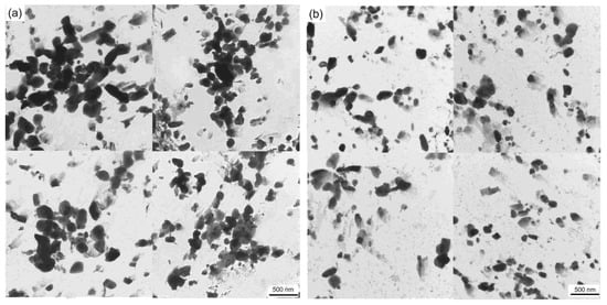
Figure 9.
TEM micrograph of tested steels after tempering for 64h at 650 °C: (a) 0.3 Si; (b) 1.0 Si.
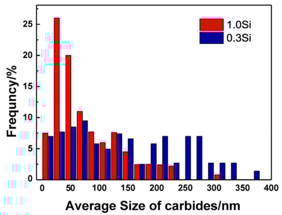
Figure 10.
Average particle size distribution of tested steels.
Table 2.
Carbide size, percentage and type for tested steels tempered for 64 h at 650 °C.
4.2. Thermodynamics of Precipitation
Thermodynamic calculations are performed by using Thermo-Calc software [22,23] and the TCFE10 database. The initial composition is set according to the steel composition of the two samples as in Table 1, and the temperature interval is set as 300–1200 °C. The calculation results regarding the composition and relative content of the alloy phase at different temperatures are shown in Figure 11. The types of carbides in the tested steels with different chromium contents are consistent. Partial enlarged views are shown in Figure 11c,d. M23C6, M2C, MC and M6C carbides are found in the 600–650 °C tempered samples with different Si contents. However, the amount of precipitation of M6C carbide in 0.3 Si steel in this experimental temperature range is rare and almost zero, while that of M6C-type carbide in 1.0 Si steel is high. Studies have also shown that the addition of Si can control the evolution of M2C→M6C and the coarsening of grain boundary carbide [24,25].
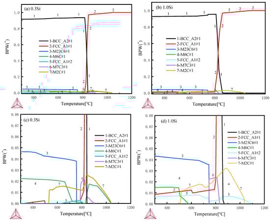
Figure 11.
Thermodynamic calculations by Thermo-Calc software with TCFE10 database: (a,b) 300–1200 °C full views, (c,d) 300–1200 °C partial enlarged views.
Smaller and dispersed carbides led to the better thermal stability of the 1.0 Si steel sample. The 1.0 Si steel sample can obtain smaller, dispersed carbides mainly because the α-Fe crystal structure is distorted by the Si atoms during tempering and heat preservation, which promotes the precipitation of C atoms from the martensite matrix, but hinders the C atoms’ diffusion movement, inhibiting the aggregation and growth of carbides, so the overall size of the carbides of the 1.0 Si steel sample is smaller, and a large number of fine secondary carbides are precipitated in the matrix. During the heat preservation process, the growth of cementite in steel depends on the diffusion of C atoms in supersaturated ferrite to cementite. Furthermore, the solubility of Si in cementite is low. Some scholars have analyzed the matrix composition around carbides and showed that the concentration of Si around the carbides of bainitic and martensitic steel samples is relatively high, and the direction of the Si flux is opposite to the direction of C atom diffusion [26]. It is enriched at the carbide–ferrite matrix interface, which reduces the flux of C atoms from the matrix into the M6C carbide and delays its growth (Figure 12). Therefore, the 1.0 Si steel sample has better thermal stability at high temperature for a long time.
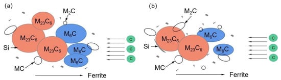
Figure 12.
Carbide growth model: (a) 0.3 Si; (b) 1.0 Si.
5. Conclusions
In this study, the microstructure evolution and mechanical properties of 0.3 Si and 1.0 Si hot-work die steel after different tempering times are investigated, and the main conclusions are as follows:
- During the thermal stability experiment, the 1.0 Si steel sample always has higher hardness than the 0.3 Si steel sample. The hardness of the 1.0 Si steel sample is 2.0 HRC greater than that of the 0.3 Si steel sample after being held at 600 °C for 64 h. The former is 4.1 HRC greater than the latter one after being held at 650 °C for 64 h. Thus, the thermal stability of the 1.0 Si steel sample is better than that of the 0.3 Si steel sample;
- The two tested steel samples are insulated at 650 °C. With the extension of holding time, the matrix structure gradually recovers, the characteristics of the martensitic lath are weakened and the number of carbides increases. After being held at constant temperature for 64 h, the percentage of carbides with a size of 1–100 nm in the 1.0 Si steel matrix is 34% greater than that of the 0.3 Si steel sample, and the percentage of carbides with a size of 200–400 nm is 30% greater than that of the 0.3 Si steel sample;
- After being tempered at 650 °C, Mo-rich M6C-type carbide particles in the 0.3 Si steel sample show an obvious aggregation and growth phenomenon. In addition, Si hinders carbon atomic diffusion and inhibits M6C roughening, making the average particle size in the 1.0 Si steel sample small. Additionally, more small-sized V-rich MC-type and Mo-rich M2C secondary carbides are precipitated during the tempering process. These factors endow the 1.0 Si steel sample with more excellent thermal stability.
Author Contributions
Conceptualization, X.W.; methodology, L.L.; software, Z.C.; validation, Z.C., L.L. and X.W.; formal analysis, L.L. and Z.C.; investigation, L.L. and Z.C.; resources, Z.C.; data curation, L.L. and Z.C.; writing—original draft preparation, L.L.; writing—review and editing, X.W.; visualization, Z.C.; supervision, L.L.; project administration, X.W.; funding acquisition, X.W. All authors have read and agreed to the published version of the manuscript.
Funding
This work is supported by the Guangdong Provincial Key R&D Programme (2020B010184002).
Institutional Review Board Statement
Not applicable.
Informed Consent Statement
Not applicable.
Data Availability Statement
No data are reported.
Conflicts of Interest
The authors declare no conflict of interest.
References
- Medvedeva, A.; Bergström, J.; Gunnarsson, S.; Andersson, J. High-temperature properties and microstructural stability of hot-work tool steels. Mater. Sci. Eng. A 2009, 523, 39–46. [Google Scholar] [CrossRef]
- Casati, R.; Coduri, M.; Lecis, N.; Andrianopoli, C.; Vedani, M. Microstructure and mechanical behavior of hot-work tool steels processed by Selective Laser Melting. Mater. Charact. 2018, 137, 50–57. [Google Scholar] [CrossRef]
- Fu, J.; Wang, J. Effect of Mo Content on the Thermal Conductivity and Corrosion Resistance of Die Steel. J. Mater. Eng. Perform. 2021, 30, 8438–8446. [Google Scholar] [CrossRef]
- Sjöström, J. Chromium Martensitic Hot-Work Tool Steels-Damage, Performance and Microstructure. Ph.D. Thesis, Karlstad University Press, Karlstad, Sweden, 2004. [Google Scholar]
- Du, N.; Liu, H.; Fu, P.; Liu, H.; Sun, C.; Cao, Y.; Li, D. Microstructural Stability and Softening Resistance of a Novel Hot-Work Die Steel. Crystals 2020, 10, 238. [Google Scholar] [CrossRef]
- Zhang, Z.; Delagnes, D.; Bernhart, G. Microstructure evolution of hot-work tool steels during tempering and definition of a kinetic law based on hardness measurements. Mater. Sci. Eng. A 2004, 380, 222–230. [Google Scholar] [CrossRef]
- Kim, B.; Sietsma, J.; Santofimia, M. The role of silicon in carbon partitioning processes in martensite/austenite microstructures. Mater. Des. 2017, 127, 336–345. [Google Scholar] [CrossRef]
- Huyghe, P.; Caruso, M.; Collet, J.-L.; Dépinoy, S.; Godet, S. In Situ Quantitative Assessment of the Role of Silicon During the Quenching and Partitioning of a 0.2C Steel. Met. Mater. Trans. A 2019, 50, 3486–3494. [Google Scholar] [CrossRef]
- Tian, J.; Xu, G.; Jiang, Z.; Wan, X.; Hu, H.; Yuan, Q. Transformation Behavior and Properties of Carbide-Free Bainite Steels with Different Si Contents. Steel Res. Int. 2018, 90, 1800474. [Google Scholar] [CrossRef]
- Sourmail, T.; Millot-Méheux, M. Thermal and mechanical stability of retained austenite in 1%C bearing steels with varying Si contents. Mater. Sci. Technol. 2016, 32, 1126–1132. [Google Scholar] [CrossRef]
- Liu, M.; Xu, G.; Tian, J.; Wei, Z.; Zhang, Q. Effect of Si content on kinetics of bainitic transformation and properties of low car-bon bainite steels. J. Iron. Steel Res. Int. 2019, 31, 982. [Google Scholar] [CrossRef]
- Kim, B.; Celada, C.; Martín, D.S.; Sourmail, T.; Rivera-Díaz-Del-Castillo, P. The effect of silicon on the nanoprecipitation of cementite. Acta Mater. 2013, 61, 6983–6992. [Google Scholar] [CrossRef]
- Zeng, Y.; Wu, X.; Xia, S.; Zuo, P. Influence of Ni on the Thermal Stability of a New Die Casting Steel. Mater. Rev. 2017, 31, 72. [Google Scholar] [CrossRef]
- Delagnes, D.; Lamesle, P.; Mathon, M.; Mebarki, N.; Levaillant, C. Influence of silicon content on the precipitation of secondary carbides and fatigue properties of a 5%Cr tempered martensitic steel. Mater. Sci. Eng. A 2005, 394, 435–444. [Google Scholar] [CrossRef]
- Zhou, Q.; Wu, X.; Min, N. Effect of Si addition on kinetics of martensitic hot-work die steel during tempering. Met. Mater. Int. 2011, 17, 547–552. [Google Scholar] [CrossRef]
- Zhou, Q.C. Effect of Silicon on H13 Type Hot Work Die Steel. Ph.D. Thesis, Shanghai University, Shanghai, China, 2012. [Google Scholar]
- Miyamoto, G.; Oh, J.; Hono, K.; Furuhara, T.; Maki, T. Effect of partitioning of Mn and Si on the growth kinetics of cementite in tempered Fe–0.6 mass% C martensite. Acta Mater. 2007, 55, 5027–5038. [Google Scholar] [CrossRef]
- Kozeschnik, E.; Bhadeshia, H.K.D.H. Influence of silicon on cementite precipitation in steels. Mater. Sci. Technol. 2008, 24, 343–347. [Google Scholar] [CrossRef]
- Sun, W.; Qin, X.; Guo, J.; Lou, L.; Zhou, L. Thermal stability of primary MC carbide and its influence on the performance of cast Ni-base superalloys. Mater. Des. 2015, 69, 81–88. [Google Scholar] [CrossRef]
- Chen, Y.W.; Wu, X.C.; Song, W.W.; Ya, M. Effect of carbide evolution on thermal-stability in Nb-microalloyed hot work steel. Trans. Mater. Heat Treat. 2010, 31, 75. (In Chinese) [Google Scholar] [CrossRef]
- Kwon, H.; Lee, K.B.; Yang, H.R.; Lee, J.B.; Kim, Y.S. Secondary hardening and fracture behavior in alloy steels containing Mo, W, and Cr. Met. Mater. Trans. A 1997, 28, 775–784. [Google Scholar] [CrossRef]
- Andersson, J.-O.; Helander, T.; Höglund, L.; Shi, P.; Sundman, B. Thermo-Calc & DICTRA, computational tools for materials science. Calphad 2002, 26, 273–312. [Google Scholar] [CrossRef]
- Pereira, V.S.M.; Wang, S.; Morgan, T.; Schut, H.; Sietsma, J. Microstructural Evolution and Behavior of Deuterium in a Ferritic ODS 12 Cr Steel Annealed at Different Temperatures. Met. Mater. Trans. A 2022, 53, 874–892. [Google Scholar] [CrossRef]
- Jiang, L.; Zhang, W.-Z.; Xu, Z.-F.; Huang, H.-F.; Ye, X.-X.; Leng, B.; Yan, L.; Li, Z.-J.; Zhou, X.-T. M 2 C and M 6 C carbide precipitation in Ni-Mo-Cr based superalloys containing silicon. Mater. Des. 2016, 112, 300–308. [Google Scholar] [CrossRef]
- Xu, Z.-F.; Dong, J.-S.; Jiang, L.; Li, Z.-J.; Zhou, X.-T. Effects of Si Addition and Long-Term Thermal Exposure on the Tensile Properties of a Ni–Mo–Cr Superalloy. Acta Met. Sin. Engl. Lett. 2015, 28, 951–957. [Google Scholar] [CrossRef]
- Thomson, R.; Miller, M. The partitioning of substitutional solute elements during the tempering of martensite in Cr and Mo containing steels. Appl. Surf. Sci. 1995, 87–88, 185–193. [Google Scholar] [CrossRef]


Disclaimer/Publisher’s Note: The statements, opinions and data contained in all publications are solely those of the individual author(s) and contributor(s) and not of MDPI and/or the editor(s). MDPI and/or the editor(s) disclaim responsibility for any injury to people or property resulting from any ideas, methods, instructions or products referred to in the content. |
© 2023 by the authors. Licensee MDPI, Basel, Switzerland. This article is an open access article distributed under the terms and conditions of the Creative Commons Attribution (CC BY) license (https://creativecommons.org/licenses/by/4.0/).