Article

Finite Element Analysis of Large Plastic Deformation Process of Pure Molybdenum Plate during Hot Rolling

1
School of Metallurgy Engineering, Xi’an University of Architecture and Technology, Xi’an 710055, China
2
National and Local Joint Engineering Research Center for Functional Materials Processing, Xi’an University of Architecture and Technology, Xi’an 710055, China
3
Northwest Institute for Non-Ferrous Metal Research, Xi’an 710016, China
*
Authors to whom correspondence should be addressed.
Metals 2023, 13(1), 101; https://doi.org/10.3390/met13010101
Submission received: 7 November 2022 / Revised: 20 December 2022 / Accepted: 30 December 2022 / Published: 3 January 2023
(This article belongs to the Special Issue Preparation of High-Performance Non-ferrous Metals and Composites)

Abstract

:
The rare molybdenum resources are being increasingly used in heavy industries. In this study, the common unidirectional and cross hot rolling operations, for pure molybdenum plates, were numerically simulated by using MSC. Marc software. An elastic–plastic finite element model was employed, together with the updated Lagrange method, to predict stress and strain fields in the workpiece. The results showed that there was a typical three-dimensional additional compressive stress ( σ y > σ z > σ x ) in the deformation zone, while strain could be divided into uniaxial compressive strain and biaxial tensile strain ( ε y > ε x > ε z ). Tensile stress σ x increased with the accumulation of reduction and the decrease in friction coefficient at the edge of the width spread. More importantly, the interlaced deformation caused by cross-commutations, which were helpful in repairing the severe anisotropy created by unidirectional hot rolling. The evolution of the temperature field of pure molybdenum plate was investigated. The surface quenching depth of the pure molybdenum plate was about 1/6 H under different initial temperatures and reductions. In addition, the fundamental reason for the nonuniform distribution of stress and strain fields was the joint influence of rolling stress, contact friction, and external resistance. By comparing the theoretical simulation value of the model with the experimental verification data, we found that the model was aligning well with the actual engineering.

1. Introduction

Pure molybdenum (BCC), which has a high stacking fault energy and is a typical representative of rare and strategic refractory metal (melting point 2620 °C), is often utilized for producing high-value products. Due to its excellent high-strength and -rigidity properties, good electrical and thermal conductivities at elevated temperatures, and its strong corrosion resistance, it is extensively used in aerospace, mechanical electronics, nuclear industry, and other fields [1,2,3]. However, molybdenum has a higher ductile-to-brittle transition temperature, poor oxidation resistance at high temperatures, and fewer slip systems that can operate independently, which makes its manufacturing and application extremely difficult [4,5]. Conventional molybdenum products include bars, plates, and wires. Among them, the most widely applied and potentially valuable is sheet metal processing, which has to be handled through a rolling process [6]. Currently, there are two kinds of thermal deformation of molybdenum sheets: unidirectional hot rolling (UHR) and cross hot rolling (CHR), but they are often accompanied by a variety of defects, such as surface edge cracks and delamination [7,8,9]. Essentially, these are due to the serious genetic effect of passes and the unreasonable control of processing parameters; as such, technical improvements are urgently needed.
Hot rolling is a continuous inheritance process that integrates the mutual iterative influence of the temperature and force field variables. The main variables are rolling pressure, temperature, rolling speed, reduction, roll diameter, and friction coefficient. The material and geometric nonlinearity and boundary condition nonlinearity are the core and dominant factors of thermal–mechanical coupling behavior [10,11,12]. Therefore, this is a very complicated problem, and it is not easy to intuitively and rationally explore a reasonable range of molding parameters and micrometallurgical characteristics through simple experimental trial-and-error methods. The technology of finite element analysis (FEA), as a powerful and efficient numerical simulation tool, has been widely recognized in academia and industry, especially in plastic forming of rolling, and plays an irreplaceable role in the description of material flow behavior [13,14]. Commercially available software packages such as MSC. Marc, ABAQUS, DEFORM, etc., also greatly reduce the workload of engineers. Most of the traditional mathematical models are based on the elastic–plastic and rigid-plastic ones, assuming that the strip is isotropic and homogeneous, and the interface boundary conditions refer to the shear or Coulomb friction model [15,16]. In the more recent research, various factors have been more realistically taken into account, such as setting the hybrid friction factor, treating the interfacial heat transfer coefficient as a function of temperature and pressure, and exerting interface lubrication [17,18], which have greatly improved the practical value of the resulting calculation. The approach of arbitrary Lagrangian and Eulerian (ALE) was employed to enhance the previous idea of updated Lagrange [19,20,21]. In recent decades, generally, 2D/3D coupled thermo–mechanical simulation has seen applications in lightweight alloys (aluminum and magnesium alloys) and steels [22,23,24,25,26], but studies in the field of refractory metal are still relatively scarce, especially the development of molybdenum sheets [27,28]. Although the deformation patterns of CHR and UHR is similar, the transition of rolling direction makes the field state exchange dramatically, and the difference in mechanical properties in both vertical and horizontal orientations is also apparently compromised. However, the genetic pattern of these characteristic field quantities does not seem to be clear in the current research [29,30], so it needs further exploration and exploitation. In order to reduce the rolling scrap caused by manual operation and to increase the yield of molybdenum sheets, it is necessary to systematically study the formation of sheets by means of computer design and parameter optimization.
The main aim in this study was to construct a numerical model for the UHR and CHR of molybdenum plates and carefully analyze the fields of temperature, stress, strain, and additional stress–strain relationships before and after cross reversing. Subsequently, the parameters related to the depth of chilling, the distribution of additional tensile/compressive stresses in width, and the history of plastic strain in the rolling direction on the surface of the plate are discussed and designed, which will provide important guidance for restraining the anisotropy, improving the uniformity and mechanical properties in the vertical and horizontal directions, and developing deep processing terminal products of sheet metal.

2. Experimental Details

In this study, the slab was prepared by powder metallurgy, followed by hot rolling. The detailed process is shown in Figure 1. First, the molybdenum powder (Jinduicheng molybdenum Co., Ltd., Xi’an, China) with a purity greater than 99.95% was loaded into the mold; second, it was pressed into billets by cold isostatic pressing in a YT79-500 hydraulic machine (pressure was 180 MPa) (Jinduicheng molybdenum Co., Ltd., Xi’an, China), and then sintered by solid-phase staged sintering in a medium-frequency induction-sintering furnace (Jinduicheng molybdenum Co., Ltd., Xi’an, China) (sintering temperature was 1880 °C, and sintering time was up to 18.5 h). Finally, the obtained sintered billets were heated to 1320 °C in a stove with hydrogen atmosphere protection (Xi’an gemei metal materials Co., Ltd., Xi’an, China) for about two hours and then immediately removed for rolling. The rolling schedule is shown in Table 1.

3. Finite Element Model

A 3D model for hot rolling was developed using the commercial finite element software MSC. Marc, mainly simulating the UHR and CHR processes. We only studied the coupling law of macro stress, strain, and additional stress and strain with temperature under two rolling modes. The geometric model of the plate and roll was established through the pretreatment interface Mentat. The rolled plate was a 13.2 × 50 × 100 mm rectangular blank. Then, an 8-noded hexahedral element was used for 3D mesh generation, producing 19,200 elements. In addition, in this simulation, we assumed that the pure molybdenum plate was an isotropic continuous medium, and we did not consider the microporosity or inclusion problems occurring in the preparation and sintering of molybdenum plates. Then, the 8-noded hexahedral elements with good calculation accuracy and deformation performance were used for meshing in the roll and plate. Considering the symmetry of the rolling process, only half of the plate was modeled. To simplify its complexity, the roll in contact with the plate was meshed with biased density. The work roll was regarded as a rigid body with heat transfer, and the plate was an elastic–plastic body. Due to the different reductions of pure molybdenum plates, the roll gap spacing of the two high mills was accordingly adjusted, but the roll gap spacing remained unchanged during the single-pass operation. Additionally, the ideal boundary conditions that could be considered are portrayed in Figure 2. As known, temperature and strain rate are very sensitive to rheological behavior; hence, the previously established constitutive equation [31] was taken into account to describe the formation of pure molybdenum in this study. The updated Lagrangian method was employed to address the process of large plastic deformation. The Mises yield criterion was given to the yield of the material, and the interface contact behavior complied with the shear friction model. The relevant considered parameters are shown in Table 2.

4. Results and Discussion

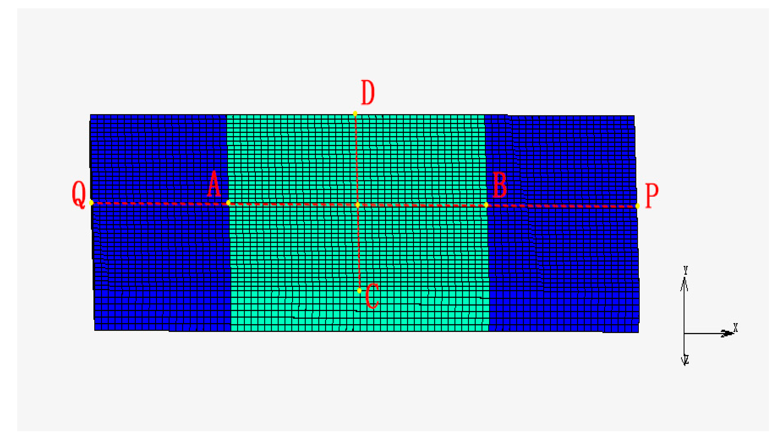
4.1. Analysis of Deformation Zone

As displayed in Figure 3, the typical historical characteristics of the temperature field, and stress and strain field before and after transition were discussed by taking the deformation zone and outer region (marked in light cyan) as an example in the first pass of UHR. Note that AB is the center line of the length, and DC is the symmetry line in the width. The rolled plates in Figure 3 were prepared by two processes. The RD1 of the first rolling plate was along AB direction, and UHR was performed twice. The second plate RD1 was along AB direction. After one UHR preparation, the plate rotated 90° perpendicular to the rolling plane, the RD2 changed from AB to DC, and one CHR preparation was completed. The deformation zones of UHR and CHR were discussed and analyzed by using lines of DC and AB crossing their neutral planes, respectively.

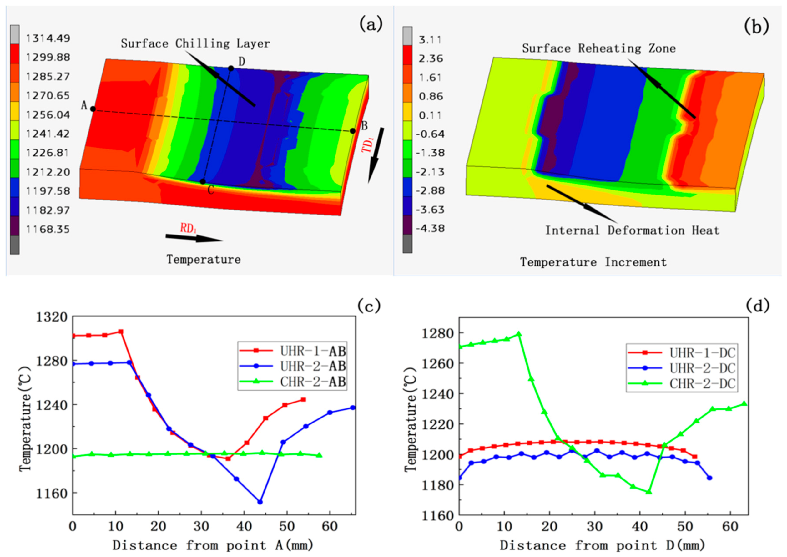
4.1.1. Analysis of Temperature Field

The state of the temperature field and temperature increase contour (dT/dt) of the first pass in the deformation zone are shown in Figure 4a,b respectively. The temperature distribution of the plate was inhomogeneous. There are three typical thermal phenomena during plate formation: surface chilling, surface reheating, and internal plastic heat generation. A severe chilling layer is generated on the surface of the plate that is in contact with the roll, and the internal distortion caused by plastic deformation occurs in the interior of the sheet; then, the conduction from the inside to the surface appears at the exit. These three thermal effects together contribute to the heat generation and energy loss of the molybdenum plate until a transient dynamic thermal balance is established. In contrast with Figure 4c,d, we found that the temperature gradient in the longitudinal and transverse directions (AB, DC) before and after revolved was more competitive, and there was alternating floating. This was a result of the combined effects of heat inside the strip, thermal transfer on the interface of the sheet and rollers, as well as the convection and radiation between the plate surface and surrounding environment. In other words, the evolutionary histories of these phenomena are attributed to the dynamic thermal equilibrium of the plate during energy transfer and heat loss.

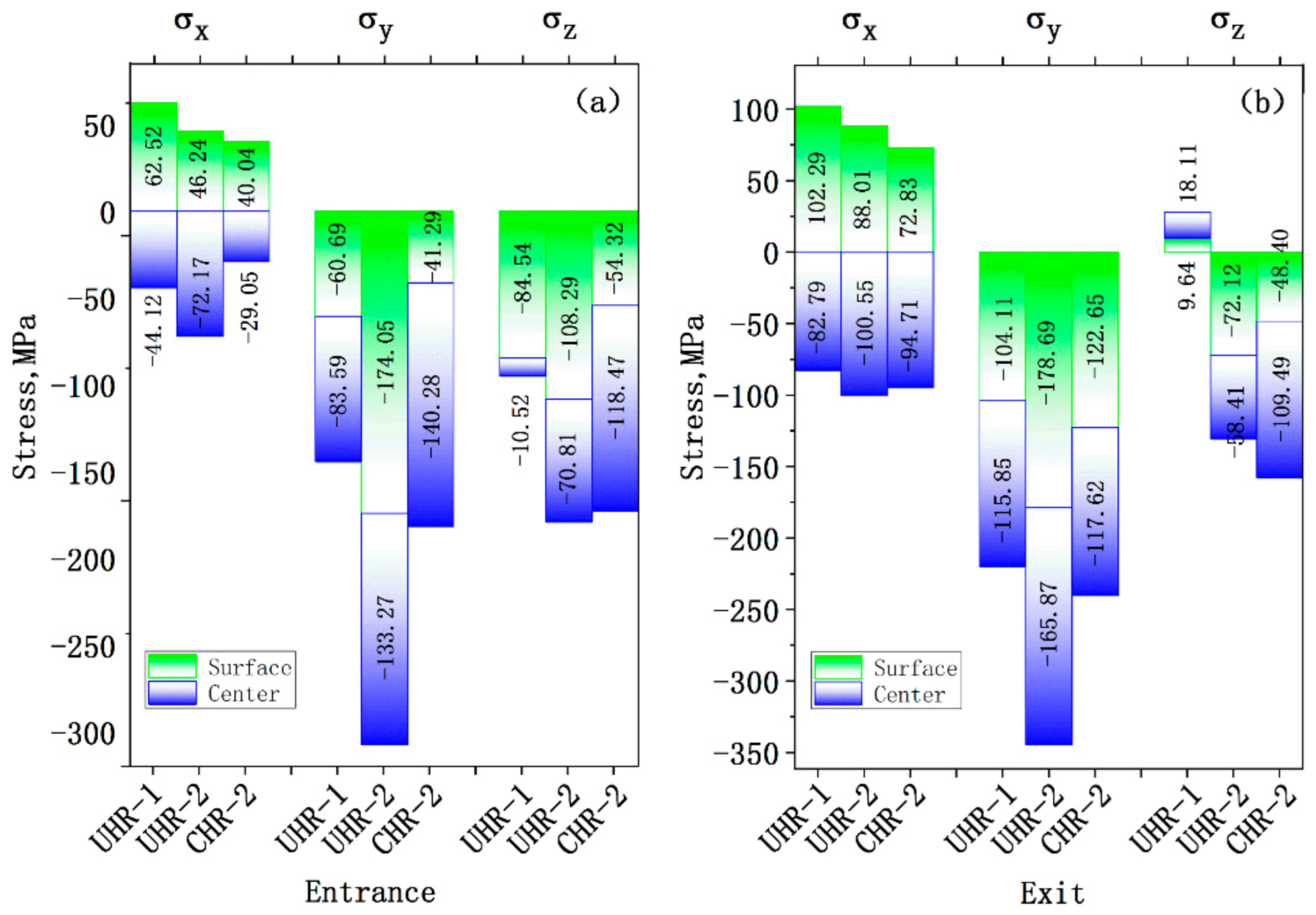
4.1.2. Analysis of Stress Field

Stress, as the strength of internal force, reflects the equilibrium behavior of particles inside a body under external loads. In order to further explore the nature of the large metal flow gradient in the free deformation zone, in the analysis, we focused on the internal force evolution of the entrance and exit at the junction of the free deformation zone and the outer zone (as shown in Figure 5a,b). Furthermore, the state of additional stress in different orientations of rolling direction (RD), thickness direction (ND), and width direction (TD) was described in detail by means of microelements parallel to the coordinate plane. The surface at the entrance and exit, in two processes, had tensile stress in the RD1 and RD2 directions, while there was additional compressive stress in the center. Specifically, in the first pass, the tensile stress on the surface was greater than the compressive stress in the center, resulting in a larger force field gradient at the entrance and exit, while the compressive force in the core was dominant in the second pass of UHR, which made the plate exhibit compressibility along the thickness. Similarly, the difference in competition in tension/compression stress between the surface and center appeared to be smaller in CHR. That is, the coexistence of tension and compression between the surface and center could significantly diminish the stress difference and substantially decrease the nonuniformity along the thickness direction, i.e., a “synchronization effect”. With the increase in rolling passes, the plate thinned, which also showed that the equivalent stress along the thickness direction had basically penetrated into the center, which is of great significance for the microporosity welding. The atoms reached the gravitational range of metal bond, completing the microstructure transformation from the sintering state to rolling. Moreover, the σ y effect along the thickness direction was negative under these rolling modes; compared with CHR, the integral compression effect of UHR seems to be more acute. Additionally, along the σ z direction, the compressibility under the two processes was weakened, which indicated that there may have been a certain pre-tension stress trend from the central section to the edge in each direction of width (TD1/TD2) before and after rotation, promoting the formation of spreading.
The distribution of equivalent stress along the longitudinal/transverse section in the deformation zone under the two processes is depicted in Figure 6a,c,e. In general, regardless of the rolling method applied, the distribution of equivalent stress in the deformation zone was not homogeneous. The longitudinal section in Figure 6a is clearly divided into an inflexible domain (I), an easy deformation area (II), and two free deformation zones (III, IV). Among them, the inflexible domain was located on the surface, which experienced severe friction stress in connection with the roller, so the equivalent stress was the largest (208.74 MPa). With advancing deformation, the stress in the easy deformation area gradually decreased from the surface to the center. Because the free deformation zone was close to the outer region, its static obstruction could not resist the compression behavior of the roller in the thickness of the plate, so metal flow along the direction of RD1 accelerated, resulting in the lowest equivalent stress in this area. Similar profiles were also observed in the longitudinal sections in (c) and (e). In addition, there was a certain amount of prestress near the entrance and exit of the outer region, and the farther its distribution from the deformation zone, the weaker the intensity of the stress.
Figure 6a,h show that the equivalent stress of the first pass of UHR was in the range of 195.6–199.2 MPa, and its fluctuation was very small. The distribution slightly increased from the center to the edge of the plate and then gradually decreased on the transverse surface, which is explained in more detail in Figure 6b. Although the elements in the central region were forced to flow along RD1 and TD1 by the pressure of the rolls, the severe interfacial friction behavior of the plate–roll was reproduced, so that the directions of RD1 and TD1 were subject to the constraint of compressive stress; that is, the middle was in a state of three-dimensional compressive stress. Evidently, the effect of three-dimensional compressive stress weakened from the middle of the sheet to the edge area. The interface friction resistance significantly decreased along the TD1 direction at the edge of the plate, which gradually enhanced the width spread, and σ z dropped to zero. According to the law of volume invariance, the elongation in the rolling direction decreases with the increase in spreading in width, so tensile stress was produced in the RD1 direction. Thus, a compression–tension stress state occurred on the edge of the plate. Additionally, the rapid temperature loss caused by convection and radiation between the edge of the plate and the environment is also an objective factor that causes the larger stress on the edge. Comparing Figure 6c,h, the equivalent stress of the second pass of UHR was in the range of 231.0–234.6 MPa. However, the differentiation in stress from the middle to the edge seemed to be even worse, which was closely related to the stronger characteristics of passes of the molybdenum slab, as explained in Figure 6d. As the reduction continued, the friction resistance along the TD1 direction strikingly enhanced, the compressibility of σ z permeated to the edge profile of the sheet (points C and D), and the width spread was further limited. Simultaneously, regarding the law of volume invariance, we concluded that the decrease in width spread led to the increase in ductility along the RD1 direction, and the tensile stress of σ x sharply decreased. Remarkably, the peak value of the second pass of σ x was apparently larger than that of the first, which was also closely related to the existence of temperature decreases at the edge.
The distribution of equivalent stress in the second pass of CHR is shown in Figure 6e. The exchange of the rolling direction made the stress along AB and CD alternately change because the plate rotated 90° perpendicular to the rolling plane, and the equivalent stress was significantly more uniform than that of UHR. Figure 6g,h show that the equivalent stress of the line AB was distributed in the range of 44.9–207.9 MPa during the first pass of UHR, but it increased to 251.6–253.7 MPa after CHR. Similarly, the equivalent stress at the exit of the deformation zone on line DC after CHR was basically maintained at 134.9 MPa, reflecting that CHR strongly contributed to the improvement in excessive residual stress at the edge of UHR. Combined with the analysis in Figure 6b,f, we found that the additional stress originally in RD1 was all converted into compressibility on line AB, while the compressive stress of σ z in TD1 was replaced by the tensile stress σ x in RD2 on line DC, which was conducive to the ductility of the plate along the RD2 direction. The tensile stress of σ x in RD1 was transformed into the compressive stress of σ z in TD2, and σ z > σ x . This not only limited the width spread along TD2 in CHR but also greatly repaired the tensile stress band at the edge of UHR, especially in the biting phase and tail stage. The residual tensile stress along the lines of AB and DC occurred after the completion of the rolling action on the surface of the outer zone.
Based on the above discussion, we found that the fundamental reason for the formation of the stress field in the deformation zone under the two rolling methods is the combined action of the rolling stress, contact friction, and resistance in the outer zone [25]. The tensile stress in the RD direction is beneficial to longitudinal elongation, and the compressive stress in ND can markedly increase the shaping along the thickness direction, improving the hydrostatic pressure [32]; the aggravation of width spread is limited by the existence of compressive stress in the TD of the sheet. We found three-dimensional compressive stresses in both the longitudinal and transverse directions in the deformation zone; σ y > σ z > σ x . Based on plastic–mechanical theory, the existence of three-dimensional compressive stress is of great importance for perfecting the microstructure, improving the plasticity of materials, and decreasing the possibility of crack formation.

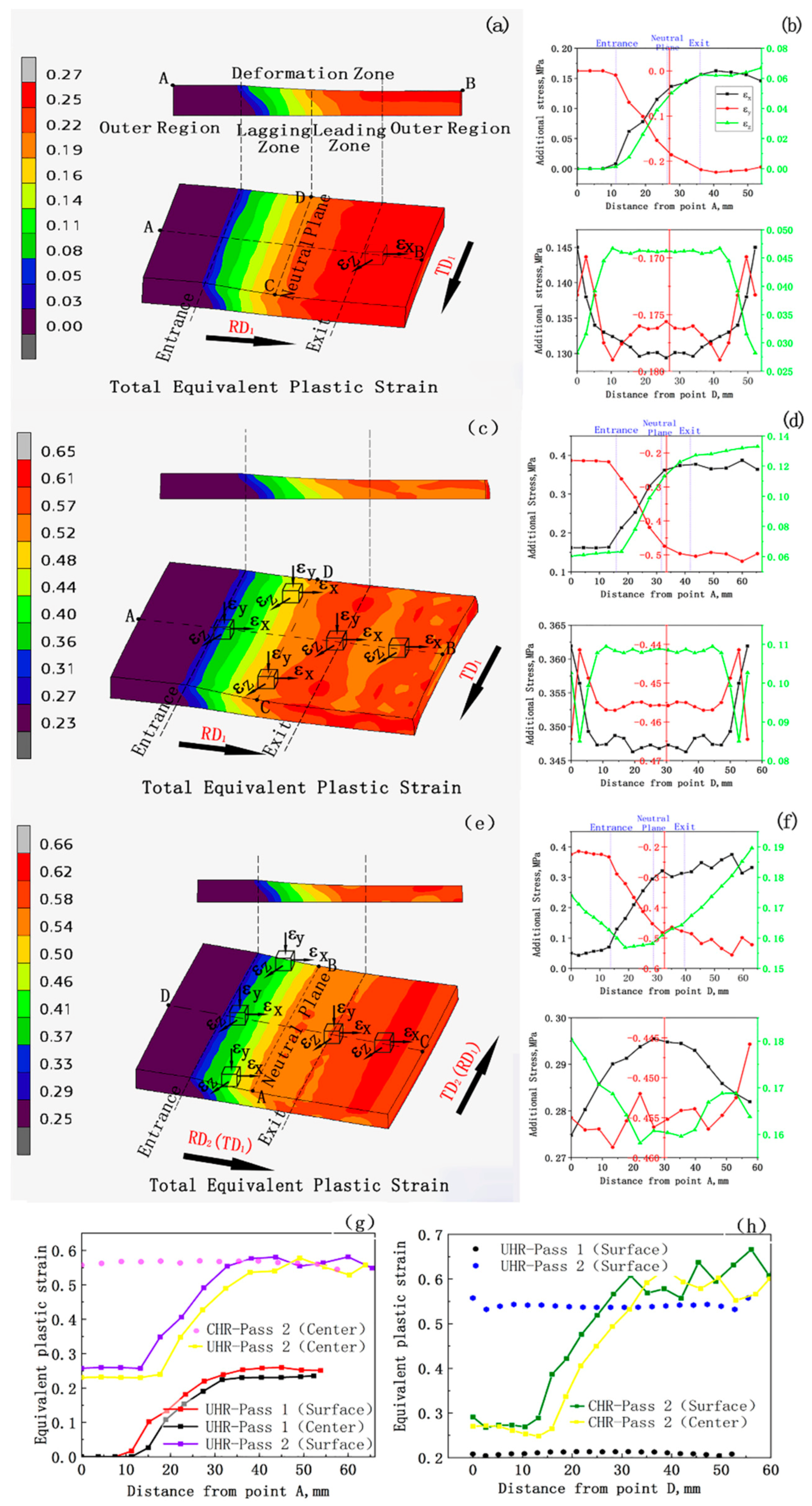
4.1.3. Analysis of Strain Field

The permanent deformation caused by continuous particle migration to the original position under the applied stress state is a key index used to measure plastic capacity, which directly determines the displacement directions of the mass points and then produces plastic strain. The distribution of equivalent plastic strain in UHR is shown in Figure 7a,c. The nonuniform strain of pure molybdenum in the thickness and transverse directions results from the discrepancy of the stress field. The strain history curve of line AB in the deformation zone under the two processes is shown in Figure 7g. Under the pressure penetration of the roll along the thickness direction of the plate, the surface experiences a larger plastic strain, while the center produces a smaller plastic strain. From the analysis of the stress field in Section 4.1.2, we found that the middle of the plate surface suffers three-dimensional compressive stress, and the action of interface shear causes a significant increase in RD1 to ε x . From the entrance to the exit of the deformation zone, the equivalent strain continuously accumulates along the rolling direction, and the difference of the equivalent plastic strain between the surface and the center narrows, indicating that the thinning makes the stress tend to be consistent along the thickness direction, so that the strain is relatively uniform; especially, the metal grains are forced to cross the neutral plane to the leading zone. Comparing with Figure 7a,c,h, the equivalent plastic strain in the first pass on the wide-directional DC was about 0.2, while that in the second pass was maintained at about 0.54. Even though the difference was very small, there was still a slight increase from the center to the edge, with especially the large peaks near the edge. This can be explained, combined with Figure 7b,d, as the boundary friction constraint being less than that of the middle, so the compressive stress σ z in TD1 weakened, and ε z presented a tensile strain distribution. It should be noted that the ε z in the middle of the sheet was larger than that at the edges, while the opposite was observed for ε x and ε y .
The equivalent strain in Figure 7e under CHR is obviously better than that of UHR when the plate was rotated 90° perpendicular to the rolling plane. Figure 7h shows that the equivalent strain trend of the longitudinal line was is basically the same as that of the longitudinal line AB; the change in the strain path made the edges in TD1 in the strain state significantly improve in UHR. The equivalent strain of TD2 on line AB was about 0.56. From in Figure 7d,f, we deduced that the additional tensile strains ε x and ε z along the AB and DC lines were alternately compensated after the vertical and horizontal cross-exchange of the plate surface, which greatly enhanced the extension of the plate along TD2. This was not similar to the stress field: there were two-dimensional tensile strains ( ε x and ε z ) and uniaxial compressive strain ( ε y ) in the deformation zone, and ε y > ε x > ε z . ε x helped to extend the plate along RD1 and RD2; ε y mainly contributed to the compression deformation along the thickness direction, while the transverse tensile strain ε z gradually decreased from the center to the edge. The resulting spread was negligible. That is, the change in the strain path caused the length and width of the plate to be interchanged, which significantly compensated for the ductility in the TD1 direction, improving the anisotropy of the plate and the potential performance along the width direction in UHR.

4.2. Optimization of Process Parameters

In summary, the evolution of the fields in the rolling deformation zone is peculiarly prone to the changes in temperature, stress, and strain; they jointly contribute to the thermal rheological behavior of pure molybdenum. To further determine the reasonable range of processing parameters, the effects of processing parameters on the depth of the surface chilling layer, additional tensile stress in the width direction, and additional strain in the rolling direction were studied.

4.2.1. Effect of Machining Parameters on Surface Chilling Layer

The intense contact between high-temperature molybdenum and cold roll negatively affects the temperature gradient of the surface of the sheet. As depicted in Figure 8a,b, taking a single pass as an example, the effects of different initial rolling temperatures and reductions on the surface chilling layer were studied under specific conditions. For molybdenum, the depth of the surface chilling remained basically the same under different situations (approximately 1/6 H, <2.2 mm), which is equivalent to the Mg alloy plate [18]. However, the chilling effect was only about 1/40 H during rough rolling [33]. This means that the low-temperature surface of molybdenum is much thicker than that of steel, and the plate temperature is extremely sensitive to the action of the cold roll. Thus, molybdenum is less convenient to use than other metals.

4.2.2. Effect of Processing Parameters on the Additional Stress along the Width of Plate

When the other conditions remain unchanged, the influence of different reduction and friction coefficients on the distribution of σ x along the width direction on the neutral surface in the second pass of the two rolling models was studied; the results are shown in Figure 9a–d. Both UHR and CHR showed tensile/compressive stress distribution in their width directions. As the number of reductions increased, the tensile stress in the edge region continued to worsen and tended to extend to the middle, while the opposite occurred with the increase in friction coefficient. It is worth noting that the maximum compressive stress in CHR was not in the core, but emerged at approximately 1/4 of the length. Owing to the rotation of the plate along the rolling plane, the contact area sharply increased, resulting in a prominent difference in the aspect ratio of resistance under a larger width, which may have caused a certain degree of convexity or distortion in the middle of the plate.

4.2.3. Effect of Reduction on Additional Strain in Rolling Direction

With the accumulation of reduction, the strain change of the nodes on the plate surface was different, but the regular pattern was basically the same. A certain point on the surface of the sheet was selected as the tracking object, and we focused on the evolution of plastic strain along the x-direction during the second passes of UHR and CHR, as described in Figure 10a,b. The plastic strain along the x-direction steadily accumulated in the longitudinal direction with continuous reductions, resulting in serious anisotropy of the plate during UHR. Even if the reduction of the second pass was consistent with that of the first pass in CHR, the strains in the RD1 and RD2 directions could not be balanced after the cross-reversing of the plate. When the reduction was controlled at about 10%, the difference in the strain peaks between the longitudinal and transverse directions was the smallest. This is because the change in the rolling direction made the sheet inherit the transverse strain in the TD1 direction before the second pass, forming a wave trough, and then expanding along that position step-by-step, creating a secondary wave peak. This proves that under this condition, cross-rolling is advisable for reducing the anisotropy of the plate.

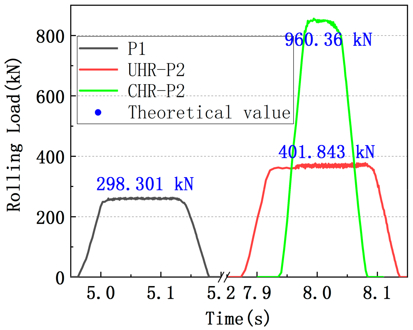
4.3. Model Validation Process

In order to further verify the accuracy of the models, an infrared pyrometer (SMART SENSOR AS892, SMART SENSOR, China) was used to measure the surface temperature of the plates in each pass. For the determination of rolling force, considering the complexity of molybdenum billet rolling, the classical Sims equation [34] was employed for theoretical verification. The specific process is shown in Figure 11 and Table 3. It can be seen that the prediction of rolling force was basically in line with the actual values, but there was a certain error between the simulated surface temperatures and the measured values. The reason is that the N and O in the air interact with molybdenum at high temperatures to produce an oxidation suction phenomenon; thus, a smear layer (MoN, MoO3) is formed, resulting in errors in pyrometer readings. Even if there is a certain error in the models, the high-temperature rheological behavior of molybdenum plates can be preliminarily predicted, laying a foundation for the subsequent production of molybdenum sheets.

5. Conclusions

The following conclusions were drawn by numerically simulating UHR and CHR of pure molybdenum sheets:
The temperature field distribution of the pure molybdenum plate is nonuniform. There are three typical thermal phenomena in the evolution of the temperature field: surface chilling layer, internal plastic deformation heat generation, and surface reheating zone after rolling. The reason for the differences between the temperature fields in the length and breadth directions is that the contact areas of the plate and roller differ during the process of the plate rolling in an alternate direction.
The reason why the temperature field is different in the length and width directions is that the contact area between the plate and the roller is different when the plate is rolling along the alternate direction.
The surface quenching depth of the pure molybdenum plate is about 1/6 H under different initial temperatures and reductions.
The distribution of the stress and strain fields of the pure molybdenum sheet is nonuniform. The fundamental reason for the nonuniform distribution of the stress and strain fields is the joint influences of rolling stress, contact friction, and external resistance. The characteristic three-dimensional compressive stress occurs in the rolling deformation zone, σ y > σ z > σ x . The strain includes uniaxial compressive stress and two-dimensional tensile stress, ε y > ε x > ε z .
Under the two processes, the existence of edge tensile stress along the width direction increases with the increases in reduction and the decrease in the friction coefficient. Compared with UHR, CHR is helpful for reducing the anisotropy of the plate.

Author Contributions

Writing—original draft, J.H. and Q.C.; Writing—review & editing, P.H.; Data curation, J.H. and Q.C.; Conceptualization, J.H.; Methodology, Q.C. and B.H.; Software, H.X.; Formal analysis, H.X.; Investigation, S.G. and X.H.; Supervision, S.L., B.H. and W.Z.; Resources, W.Z. and K.W.; Project administration, K.W.; Funding acquisition, K.W. All authors have read and agreed to the published version of the manuscript.

Funding

This research was funded by the Scientific and Technological Innovation Team Project of the Shaanxi Innovation Capability Support Plan, China (2022TD-30); the Fok Ying Tung Education Foundation (171101); Youth Innovation Team of Shaanxi Universities (2019–2022); Top Young Talents Project of “Special support program for high-level talents” in Shaanxi province (2018–2023); service local special program of education department of Shaanxi province, China (21JC016); General Special Scientific Research Program of the Shaanxi Provincial Department of Education (21JK0722); the General Projects of Key R&D Program of Shaanxi Province, China (2021GY-209).

Conflicts of Interest

The authors declare no conflict of interest.

References

  1. Liu, G.; Zhang, G.J.; Jiang, F.; Ding, X.D.; Sun, Y.J.; Sun, J.; Ma, E. Nanostructured high strengthmolybdenum alloys with unprecedented tensile ductility. Nat. Mater. 2013, 12, 344–350. [Google Scholar] [CrossRef] [PubMed]
  2. Wang, X.; Li, P.; Xue, K.M. An analysis on microstructure and grain size of molybdenum powder material processed by equal channel angular pressing. J. Mater. Eng. Perform. 2015, 24, 4510–4517. [Google Scholar] [CrossRef]
  3. Chakraborty, S.P.; Banerjee, S.; Sharma, I.G.; Suri, A.K. Development of silicide coating overmolybdenum based refractory alloy and its characterization. J. Nucl. Mater. 2010, 403, 152–159. [Google Scholar] [CrossRef]
  4. Kobayashi, S.; Tsurekawa, S.; Watanabe, T. Grain boundary hardening and triple junctionhardening in polycrystalline molybdenum. Acta. Mater. 2005, 53, 1051–1057. [Google Scholar] [CrossRef]
  5. Ahmadi, E.; Malekzadeh, M.; Sadrnezhaad, S.K. Preparation of nanostructured high temperatureTZM alloy by mechanical alloying and sintering. Int. J. Refract. Met. Hard Mater. 2011, 29, 141–145. [Google Scholar] [CrossRef]
  6. Primig, S.; Clemens, H.; Knabl, W.; Lorich, A.; Stickler, R. Orientation dependent recovery andrecrystallization behavior of hot-rolled molybdenum. Int. J. Refract. Met. Hard Mater. 2014, 48, 179–186. [Google Scholar] [CrossRef]
  7. Hu, P.; Zhou, Y.H.; Deng, J.; Li, S.L.; Chen, W.J.; Chang, T.; Hu, B.L.; Wang, K.S.; Feng, P.F.; Volinsky, A.A. Crack initiation mechanism in lanthanum-doped titanium-zirconium-molybdenum alloy duringsintering and rolling. J. Alloys Compd. 2018, 745, 532–537. [Google Scholar] [CrossRef]
  8. Cockeram, B.V. The role of stress state on the fracture toughness and toughening mechanisms of wrought molybdenum and molybdenum alloys. Mater. Sci. Eng. A 2010, 528, 288–308. [Google Scholar] [CrossRef]
  9. Xing, H.R.; Hu, P.; Zhou, Y.H.; Li, S.L.; Zuo, Y.G.; Cheng, Q.; Wang, K.S.; Yang, F.; Feng, P.F.; Chang, T. The microstructure and texture evolution of pure molybdenum sheets under various rolling reductions. Mater. Charact. 2020, 165, 110357. [Google Scholar] [CrossRef]
  10. Payan, C.; Ulrich, T.J.; Le Bas, P.Y.; Griffa, M.; Schuetz, P.; Remillieux, M.C.; Saleh, T.A. Probing material nonlinearity at various depths by time reversal mirrors. Appl. Phys. Lett. 2014, 104, 618. [Google Scholar] [CrossRef] [Green Version]
  11. Galantuccia, L.M.; Tricarico, L. Thermo-mechanical simulation of a rolling process with an FEM approach. J. Mater. Process. Tech. 1999, 92–93, 494–501. [Google Scholar] [CrossRef]
  12. Peterlik, I.; Sedef, M.; Basdogan, C.; Matyska, L. Real-time visio-haptic interaction with static soft tissue models having geometric and material nonlinearity. Comput. Graph. 2010, 34, 43–54. [Google Scholar] [CrossRef]
  13. Qayyum, F.; Shah, M.; Manzoor, S.; Abbas, M. Comparison of thermomechanical stresses produced in work rolls during hot and cold rolling of Cartridge Brass 1101. Mater. Sci. Technol. 2014, 31, 317–324. [Google Scholar] [CrossRef]
  14. Hussain, N.; Qayyum, F.; Pasha, R.A.; Shah, M. Development of multi-physics numerical simulation model to investigate thermo-mechanical fatigue crack propagation in an autofrettaged gun barrel. Def. Technol. 2020, 17, 1579–1591. [Google Scholar] [CrossRef]
  15. Zhang, S.H.; Zhang, G.L.; Liu, J.S.; Li, C.S.; Mei, R.B. A fast rigid-plastic finite element method foronline application in strip rolling. Finite Elem. Anal. Des. 2010, 46, 1146–1154. [Google Scholar] [CrossRef]
  16. Mohebbi, M.S.; Akbarzadeh, A. Constitutive equation and FEM analysis of incrementalcryo-rolling of UFG AA 1050 and AA 5052. J. Mater. Process. Technol. 2018, 255, 35–46. [Google Scholar] [CrossRef]
  17. Dixit, U.S.; Dixit, P.M. Finite-element analysis of flat rolling with inclusion of anisotropy. Int. J. Mech. Sci. 1997, 39, 1237–1255. [Google Scholar] [CrossRef]
  18. Ding, Y.P.; Zhu, Q.; Le, Q.C.; Zhang, Z.Q.; Bao, L.; Cui, J.Z. Analysis of temperature distribution in thehot plate rolling of Mg alloy by experiment and finite element method. J. Mater. Process. Technol. 2015, 225, 286–294. [Google Scholar] [CrossRef]
  19. Bagheripoor, M.; Bisadi, H. Effects of rolling parameters on temperature distribution in the hotrolling of aluminum strips. Appl. Therm. Eng. 2011, 31, 1556–1565. [Google Scholar] [CrossRef]
  20. Gouveia, B.P.P.A.; Rodrigues, J.M.C.; Bay, N.; Martins, P.A.F. Martins, Finite-element modelling of cold forward extrusion. J. Mater. Process. Technol. 1999, 94, 85–93. [Google Scholar] [CrossRef]
  21. Huang, J.P. Non-Classical Theory Plasticity: A Constitutive Model for Coupled Thermal-Mechanical Finite Elastoplastic Deformation and Application. Chongqing University, 2006. (In Chinese). Available online: https://kns.cnki.net/kcms/detail/detail.aspx?dbcode=CMFD&dbname=CMFD2007&filename=2006148520.nh&uniplatform=NZKPT&v=93TpWEsutAZV5h3mwGPWzdnhzotUQ4dlnpdtez6ZYJyOQqiUoiq6z74sAQcE-g1N.2006.04.030 (accessed on 20 October 2022).
  22. Rout, M.; Pal, S.K.; Singh, S.B. Finite element simulation of a cross rolling process. J. Manuf. Process. 2016, 24, 283–292. [Google Scholar] [CrossRef]
  23. Rout, M.; Pal, S.K.; Singh, S.B. Prediction of edge profile of plate during hot cross rolling. J. Manuf. Process. 2018, 31, 301–309. [Google Scholar] [CrossRef]
  24. Ding, H.; Hirai, K.; Homma, T.; Kamado, S. Numerical simulation for microstructure evolution inAM50 Mg alloy during hot rolling. Comput. Mater. Sci. 2010, 47, 919–925. [Google Scholar] [CrossRef]
  25. Hao, P.J.; He, A.R.; Sun, W.Q. Formation mechanism and control methods of inhomogeneousdeformation during hot rough rolling of aluminum alloy plate. Arch. Civ. Mech. Eng. 2018, 18, 245–255. [Google Scholar] [CrossRef]
  26. Lu, Y.H.; Zhu, S.C.; Zhao, Z.T.; Chen, T.L.; Zeng, J. Numerical simulation of residual stresses inaluminum alloy welded joints. J. Manuf. Process. 2020, 50, 380–393. [Google Scholar] [CrossRef]
  27. Kleiser, G.; Revil-Baudard, B.; Pasiliao, C.L. High strain-rate plastic deformation of molybdenum: Experimental investigation, constitutive modeling and validation using impact tests. Int. J. Impact Eng. 2016, 96, 116–128. [Google Scholar] [CrossRef]
  28. Priel, E.; Mittelman, B.; Trabelsi, N.; Cohen, Y.; Koptiar, Y.; Padan, R. A computational investigationof Equal Channel Angular Pressing of molybdenum validated by experiments. J. Mater. Process. Technol. 2019, 264, 469–485. [Google Scholar] [CrossRef]
  29. Zhang, X.X.; Yan, Q.Z.; Lang, S.T.; Wang, Y.J.; Ge, C.C. Preparation of pure tungsten via variousrolling methods and their influence on macro-texture and mechanical properties. Mater. Des. 2017, 126, 1–11. [Google Scholar] [CrossRef]
  30. Fan, H.Y.; Liu, S.F.; Li, L.J.; Deng, C.; Liu, Q. Largely alleviating the orientation dependence bysequentially changing strain paths. Mater. Des. 2016, 97, 464–472. [Google Scholar] [CrossRef]
  31. Hu, P.; Cheng, Q.; Li, S.L.; Xing, H.R.; Han, J.Y.; Ge, S.W.; Hua, X.J.; Hu, B.L.; Wang, K.S.; Li, L.P. Rheological behavior of pure molybdenum at high temperature considering strain compensation. Adv. Eng. Mater. 2020, 23, 2000661. [Google Scholar] [CrossRef]
  32. Nalawade, R.S.; Puranik, A.J.; Balachandran, G.; Mahadik, K.N.; Balasubramanian, V. Simulation ofhot rolling deformation at intermediate passes and its industrial validity. Int. J. Mech. Sci. 2013, 77, 8–16. [Google Scholar] [CrossRef]
  33. Chen, W.C.; Samarasekera, I.V.; Hawbolt, E.B. Fundamental phenomena governing heat transfer during rolling. Met. Mater. Trans. A 1993, 24, 1307–1320. [Google Scholar] [CrossRef]
  34. Parteder, E.; Zeman, K.; Du, H.Y.; Grill, R. Recalculation of flow stresses from industrial processdata for heavy plate rolling using a 2D finite element model. Steel Res. Int. 2012, 83, 124–130. [Google Scholar] [CrossRef]
Figure 1. Schematic diagram of the preparation process of rolled molybdenum plates. Pure molybdenum powder was formed by cold isostatic pressing, sintering in an intermediate-frequency furnace, treated in a heating furnace and pressed into molybdenum sheets by a two-roll hot-rolling mill.
Metals 13 00101 g001
Figure 2. Schematic diagram of finite element simulation and boundary conditions of molybdenum plate rolling process.
Metals 13 00101 g002
Figure 3. Schematic diagram of molybdenum plate model deformation area analysis.
Metals 13 00101 g003
Figure 4. Temperature contours of rolling deformation zone: (a) temperature field of the first pass; (b) temperature increase profile (dT/dt) of the first pass; the temperature distributions of (c) and (d) are the AB and DC lines under the two rolling conditions, respectively.
Metals 13 00101 g004
Figure 5. The distribution of additional stress at the (a) entrance and (b) exit of different passes under the UHR and CHR conditions.
Metals 13 00101 g005
Figure 6. Equivalent stress distribution in rolling deformation zone: (a) the first pass of UHR; (c) the second pass of UHR; (e) the second pass of CHR; (b,d,f) additional stress distributions along AB and DC for each of the above passes; (g,h) equivalent stress curves of different passes along AB and DC.
Metals 13 00101 g006
Figure 7. The contour maps of equivalent plastic strain in the rolling deformation zone: (a) the first pass and (c) the second pass in UHR; (e) the second pass in CHR; (b,d,f) distributions of additional strain along AB and DC lines in each pass; (g,h) evolution of equivalent strain along AB and DC lines, respectively.
Metals 13 00101 g007
Figure 8. Effect on temperature distribution along the thickness direction at the exit: (a) different initial rolling temperatures at a fixed reduction, and (b) different reductions at a constant initial temperature.
Metals 13 00101 g008
Figure 9. The effect of different parameters on the distribution of x-direction tensile stress along the width direction on the neutral surface under the two rolling modes: (a,b) reduction; (c,d) friction coefficient.
Metals 13 00101 g009
Figure 10. Effect of different reductions on plastic strain at a point on the plate surface along x-direction: (a) UHR; (b) CHR.
Metals 13 00101 g010
Figure 11. Comparison between theoretical and simulated rolling force under UHR and CHR processes.
Metals 13 00101 g011
Table 1. Expected rolling process and change in molybdenum plate thickness before and after rolling.
Pass No.Thickness before Rolling (mm)Thickness
after Rolling
(mm)
Reduction
Unidirectional Hot Rolling
(UHR)
Cross Hot Rolling
(CHR)
113.210.5620%20%
(The pass interval rotates 90° along the vertical rolling plane)
210.567.8825.38%25.38%
Table 2. Input parameters of finite element model for pure molybdenum plate rolling treatment.
MaterialPure Molybdenum
Dimensions of initial plate (mm)13.2 × 50 × 100
Diameter of roll (mm)400
Width of roll (mm)500
Number of elements19,200
Rolling speed (rad/s)2.6
Initial temperature of plate (°C)1320
Initial temperature of roll (°C)30
Coefficient of friction0.3
Contact heat transfer coefficient between plate and roll (kW m−2 K−1)10.5
Integrated heat transfer coefficient to environment (kWm−2 s−1 K−1)0.025
Coefficient of plastic work dissipated into heat0.9
Coefficient of friction work dissipated into heat0.95
Air cooling time from heating furnace to rolling mill (s)5.0
Interval time between passes (s)2.5–3.0
Table 3. Temperature comparison between measured and simulated values of plate surface under UHR and CHR processes.
Simulation ValueExperimental Value
Before first pass1298.5 °C1307.8 °C
Before second pass (UHR)1273.2 °C1261.6 °C
Before te second pass (CHR)1271.9 °C1253.5 °C
Disclaimer/Publisher’s Note: The statements, opinions and data contained in all publications are solely those of the individual author(s) and contributor(s) and not of MDPI and/or the editor(s). MDPI and/or the editor(s) disclaim responsibility for any injury to people or property resulting from any ideas, methods, instructions or products referred to in the content.

