Article

Analysis of X5CrNi18-10 (AISI 304) Steel Susceptibility to Hot Cracking in Welded Joints Based on Determining the Range of High-Temperature Brittleness and the Nil-Strength Temperature

by
Sławomir Janusz Krajewski
,
Wojciech Gutsche
and
Kamil Urbanowicz
*
Faculty of Mechanical Engineering and Mechatronics, West Pomeranian University of Technology in Szczecin, 70-310 Szczecin, Poland
*
Author to whom correspondence should be addressed.
Metals 2023, 13(10), 1633; https://doi.org/10.3390/met13101633
Submission received: 31 August 2023 / Revised: 20 September 2023 / Accepted: 21 September 2023 / Published: 22 September 2023

Abstract

:
The conducted research of X5CrNi18-10 (AISI 304) in the DSI Gleeble 3500 device aimed to determine the tensile strength of this steel at elevated temperatures, simulating welding-like conditions while sensitizing the steel to liquation cracking. The defined High-Temperature Brittleness Range (HTBR) made it possible to determine whether the material is susceptible to hot cracking, which can significantly affect the weldability of steel structures. The Nil-Strength Temperature (NST), with an average temperature of 1375 °C, was determined through a thermoplastic test, where the samples were pre-strained and subsequently heated. After the NST tests, no necking or plastic elongation of analyzed samples were noticed. The fracture of the samples was brittle at a low tensile force of 0.1 kN, indicating the value of NST (represents the upper limit of the HTBR). The lower limit of the HTBR (assumed to occur at a relative necking of 5%) was determined by heating samples to a temperature 5 °C lower than the NST and then cooling them to the specified temperature. Once the temperature was reached, the samples were subjected to tensile testing at that temperature, and the percentage necking (Z) and percentage elongation (A) were measured to determine the loss. This work indicates that the estimated Ductility Recovery Temperature (DRT) is slightly lower than 1350 °C, and X5CrNi18-10 (AISI 304) steel has a small HTBR, approximately 15 °C during heating and close to 25 °C during cooling, suggesting minimal tendencies to form hot cracks.

1. Introduction

In the case of most metallic materials, there is a risk of hot cracking; however, for some, it is sufficiently low to be considered resistant to the formation of such cracks during welding. Austenitic steel X5CrNi18-10 (AISI 304) is commonly utilized in various structures (plates [1,2], rods [3,4], bolts [5,6], tubular rods [7], etc.), mainly because of its high resistance to corrosion [8]. It remains a current subject of research in many publications.
Although austenitic steels are considered to be well-welded materials, hot cracking during welding remains a challenge [9,10]. The weldability of steel depends primarily on its chemical composition; structure; and mechanical and physicochemical properties [11,12]. Due to the high linear expansivity of austenite during solidification, austenitic steels experience significant shrinkage upon cooling. Similar behavior is observed in other structural metals, such as aluminum and its alloys and magnesium and its alloys. In industrial practice, such a kind of cracking is still a significant problem [13]. Hot cracks also occur in materials such as high-strength non-alloy steels, for example, S700MC and S960Q, during welding, where the structure is stiffened, and thermal stresses cause hot cracks of the crystallization type. An additional issue for these steels is cold cracking induced by hydrogen [14,15]. Deformations occurring during the welding of austenitic steels can lead to cracks in the Heat-Affected Zone (HAZ) and in the weld [16,17,18]. Ziewiec [19] points out that, for instance, X10CrNiCuNb18-9-3 steel is more susceptible to hot cracking compared to X5CrNi18-10 steel, but in order to fully determine this, the following features should be determined: minimal deformation causing cracks; so-called cracking threshold, i.e., the total length of all cracks; the maximum crack length. In austenitic steels, two mechanisms of hot cracking can occur. The first cracking mechanism is the partial melting of grains, followed by the rupture of a thin liquid film along crystal boundaries due to deformation during crystallization. The second cracking mechanism identified is the DDC (Ductility Dip Cracking) [20,21]. As the ability to deform decreases within a certain temperature range, the material becomes more susceptible to cracking, which can lead to the formation of cracks in places that would normally be more resistant to cracking. The DDC mechanism is particularly important in the context of welding and other thermal processes where temperature and deformation changes occur, as the shifting range of material ductility at specific temperatures can promote crack formation [20,22]. The authors Nam et al. [23] propose a post-weld heat treatment using submerged arc welding. As a result of their research, improved resistance to cracking was achieved through heat treatment at 1050 °C. This suggests that the mechanical properties of the welded joint of AISI 304 steel can be enhanced. As performed in the paper [23], Scanning Electron Microscopy (SEM) analysis of the welded joint revealed that pores and hot cracks formed during solidification after the heat treatment are imperceptible. In the article by Kiss et al. [24], it was indicated that austenitic steel can accommodate significant deformations, up to a working temperature of 1150 °C, due to its ductility. However, above 1200 °C, the material loses its ductility, and high deformation rates significantly impact the microstructure damage mechanism [24]. Kciuk and Lasok [25], using light and scanning electron microscopy with EDS microanalysis, determined the corrosion current, polarization resistance, and corrosion potential of X5CrNi18-10 steel. This material is used for high-temperature applications including various conditions, such as a nitrogen atmosphere, which enhances wear resistance (forming surface layers) [26]. Currently, in the literature, one can come across research concerning various types of numerical analyses of the influence of different inclinations of the heat source in the welding process on the shape of the weld pool and the mechanical properties of the resulting joint. The shape of the welding pool, as well as deformations and the stress state in the welded joint, have an impact on cracking. The finite element methods (FEMs) are helpful in analyzing the risk of crack formation [27].
The aim of this paper is to experimentally determine the susceptibility to hot cracking of X5CrNi18-10 (AISI 304) steel in high temperatures (in the temperature range between solidus and liquidus and below). The research was carried out to define the brittleness temperature range (BRT), and with its help, it was possible to define the susceptibility of this material to an important practical issue, named hot cracking, that defines the weldability of the analyzed material.

2. Materials and Methods

Austenitic stainless steels (ASSs) account for about 70% of stainless steel groups. They have a face-cantered cubic structure, with individual characteristics, such as weldability, corrosion resistance, toughness, and ductility [28,29]. At higher temperatures, ductile materials, such as alloy steel, can change from ductile to brittle. Upon heating, its ductility initially increases, but upon reaching a specific temperature for that material, it can entirely lose its ductile properties. This temperature at which the material loses its ductility is known as the Nil-Ductility Temperature (NDT). During heating, NDT marks the beginning of the Range of High-Temperature Brittleness (HTBR). As the material continues to heat, it gradually loses its mechanical properties until the point of reaching the Nil-Strength Temperature (NST). The temperature of NST is when the metal gains mechanical strength through formed bridges at the grain boundaries, but the joint is not yet capable of transmitting plastic deformations. It represents the upper limit of the Range of High-Temperature Brittleness (HTBR). During cooling, the lower boundary is not the same as during heating. The lower boundary during cooling is referred to as the Ductility Recovery Temperature (DRT). DRT is when the material regains its ductility. This temperature is established when a previously heated and subsequently cooled material undergoes tension testing and experiences a relative reduction of about 5%. The difference between the NST and DRT temperatures is known as the HTBR. The upper boundary of the HTBR is characterized as the temperature where connections develop among crystals that cannot undergo plastic deformations, while the lower boundary is recognized as the temperature where the metal has the ability to undergo deformations through transcrystalline slips, as shown in Figure 1.
The chemical composition of the X5CrNi18-10 austenitic steel used in this study was determined on a LECO GDS 500A glow discharge spectrometer. The percentage of elements by weight obtained from the spectrometric analysis is presented in Table 1. Performed analysis is based on determining the high-temperature brittleness range, nil-strength temperature, loss of ductility temperature, and return-to-ductility temperature.

Methodology of the Study

The aim of this study is to verify whether X5CrNi18-10 steel is susceptible to hot cracking at high temperatures. The issue during welding, casting, or plastic processing is the decrease in strength and ductility concerning the internal stresses resulting from the material’s linear expansion, which can lead to liquation or crystallization-type cracking. In such cases, it is necessary to verify whether the material is prone to hot cracking. One method of verifying this phenomenon is to conduct the Range of High-Temperature Brittleness (HTBR). In this study, a nil-strength test was carried out on 90 samples using the Gleeble 3500 device. In each simulation condition (as described in Appendix A.1, Appendix A.2, Appendix A.3 and Appendix A.4), tests were conducted on 3 samples, and the results were averaged and presented collectively. The Gleeble 3500, developed by DSI (Dynamic Systems Inc., Poestenkill, NY, USA), is a sophisticated materials testing system. It combines advanced technology to simulate extreme thermal and mechanical conditions, enabling precise research on material properties and behavior. With its versatile capabilities, the Gleeble 3500 is widely used in industries and research institutions for material characterization and process optimization. The device allows for conducting thermal–mechanical tests and physical simulations on material properties. In the conducted simulation, the influence of external factors on the formation of hot cracks in welded joints was not examined (for example, filler material, shielding gas). During the welding process, depending on the prevailing conditions (technological or metallurgical), weld imperfections, such as non-metallic inclusions or the occurrence of pores, can occur in the weld pool area. The just-mentioned issue was not taken into account in the conducted study. The tests were performed in a vacuum environment on the base material (AISI 304) and without the addition of any filler material (wire, rod, or electrode). The detailed step-by-step methodology for investigating at various temperatures and the procedure for preparing samples for testing are presented in Appendix A. Detailed information on the preparation of X5CrNi18-10 steel samples is described in Appendix A.1.
The Nil-Strength Temperature (NST) is obtained during the examination of brittleness and susceptibility to cracking of steel (and other metallic materials) at very high temperatures. It is a crucial parameter for welding and the selection of forming temperatures. The technical literature related to welding and material forming processes defines the zero-strength temperature as the temperature at which steel loses all its strength due to the melting of grain boundaries during heating. At this temperature, which is lower than the solidus temperature, steel is unable to bear any load [31,32,33,34,35,36]. An example of a window with the NST program is shown in Figure 2. Figure 3 illustrates the temperature change over time. The two lines overlap almost entirely, except for a brief interruption representing the actual temperature, indicated by the black line, and the set temperature, represented by the red line. From the graph, one can deduce the Nil-Strength Temperature (NST), which, for this sample, was approximately 1388 °C at a preloading of 0.09 kN. More Nil-Strength Temperature (NST) testing details can be found in Appendix A.2.
The Nil-Ductility Temperature (NDT) is defined as the on-heating temperature, where ductility is reduced to zero. Essentially, this can be viewed as the temperature of liquation onset, where grain boundary surfaces are coated by a thin continuous liquid film [31,32,33,35]. More details about performed NDT testing can be found in Appendix A.3.
The temperature at which measurable ductility is regained is called the ductility recovery temperature (DRT). At the DRT, the liquid that has formed during the high-temperature deformation process begins to solidify, allowing the material to regain its capacity for plastic deformation. This transition from liquid to solid state enables the material to once again exhibit ductile behavior under a load [33,35,36]. For more details about performed DRT testing, please see Appendix A.4.
All collected results were tabulated, and graphs illustrating the test progress were generated using the data from the machine. Presenting data obtained from experimental studies in the Gleeble 3500 thermal–mechanical simulator requires the application of formulas from material strength analysis. To calculate percentage necking, percentage elongation, and stress, Formulas (1)–(4) were applied. The cross-sectional area of the sample before testing is defined with Formula (1). Formula (1) is necessary for calculating stresses in the sample upon rupture (2). Formulas (3) and (4) are utilized to calculate, respectively, percentage elongation and percentage necking.
S 0 = π d 2 4
R m = F m S 0
A = L u L 0 L 0 100 %
Z = S 0 S u S 0 100 %
where d—specimen diameter, S0—original specimen cross-sectional area [mm2], Rm—tensile strength [MPa], Fm—maximum tensile force [MPa], L0—original gauge length [mm], Lu—final gauge length [mm], A—elongation (non-proportional) [%], Z—reduction of area at fraction [%], and Su—final cross-sectional area [mm2].
For initial macroscopic examination, a Digital SLR Camera Nikon D80 with a Nikkor AF 60 mm f/2.8 D Macro lens (Nikon Corporation, Tokyo, Japan) was used, mounted on a Kaiser RS-1 Copy Stand Kit with a grid size 10 mm counterbalanced column (halogen lighting) (Figure 4). A more detailed macroscopic samples examination was performed using the Nikon AZ100 × 0.5 microscope (Nikon Corporation, Tokyo, Japan) equipped with an LED illumination system (Figure 5, Figure 6, Figure 7, Figure 8, Figure 9, Figure 10, Figure 11, Figure 12, Figure 13, Figure 14 and Figure 15).
The microstructure of the examined samples was described using field emission scanning electron microscopy (FE-SEM) with the Hitachi SU-70 instrument (Hitachi, Naka, Japan) (Figure 16, Figure 17, Figure 18 and Figure 19).

3. Results

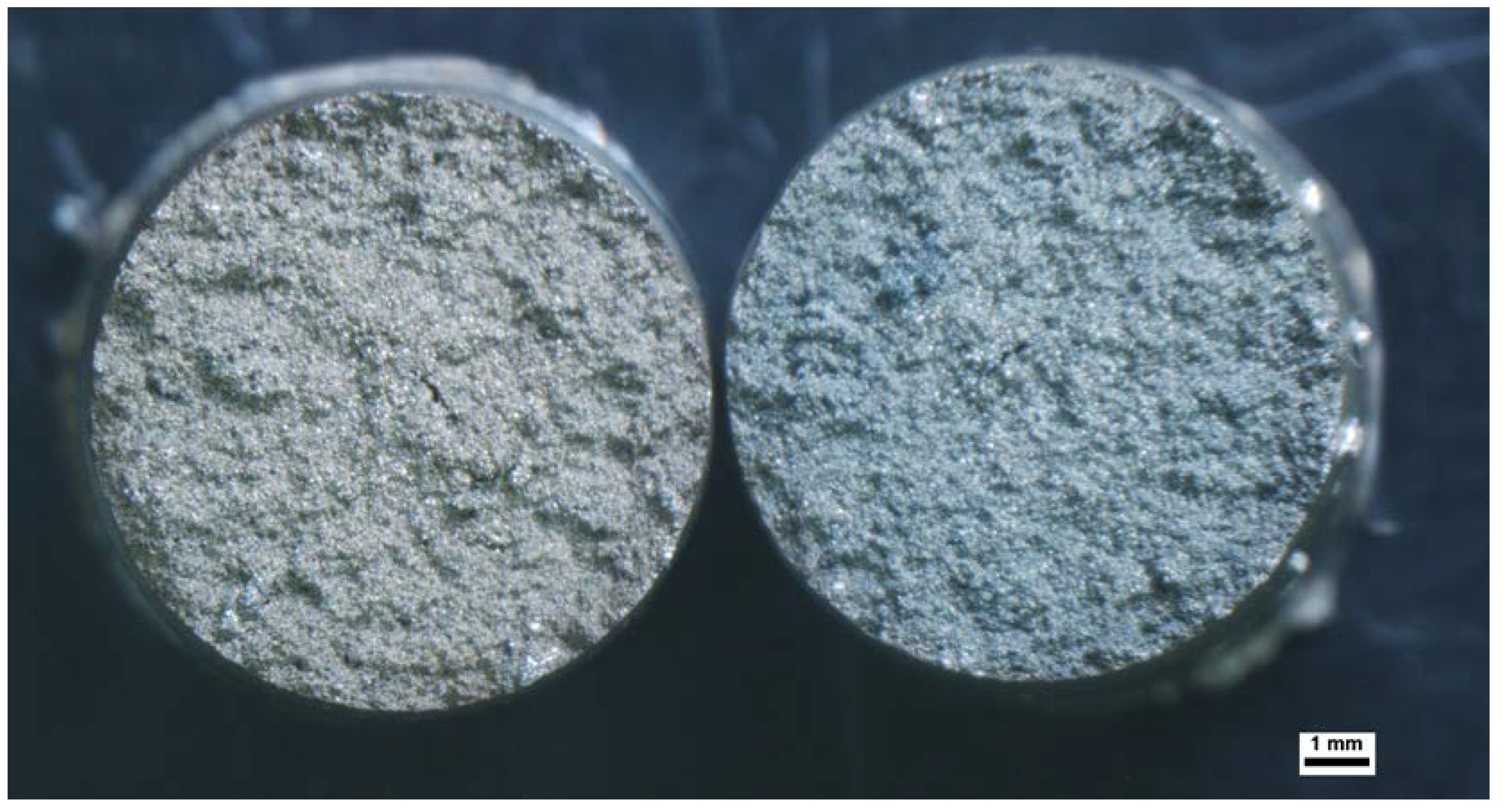
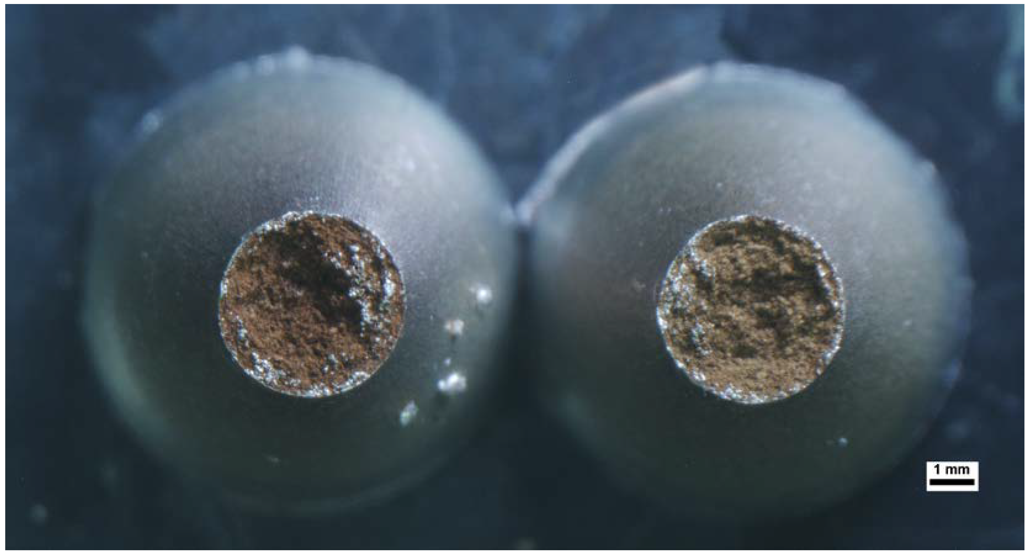
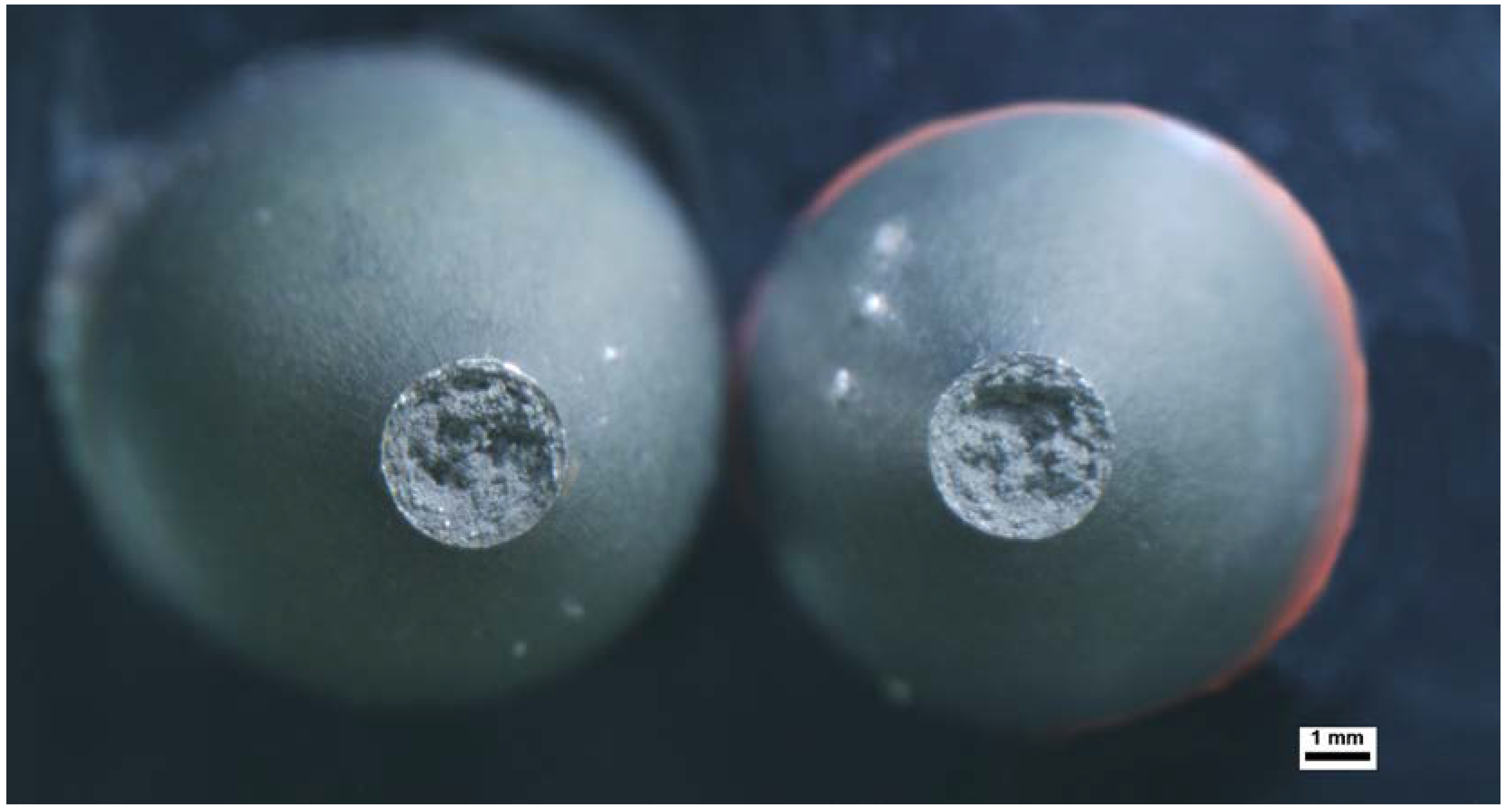
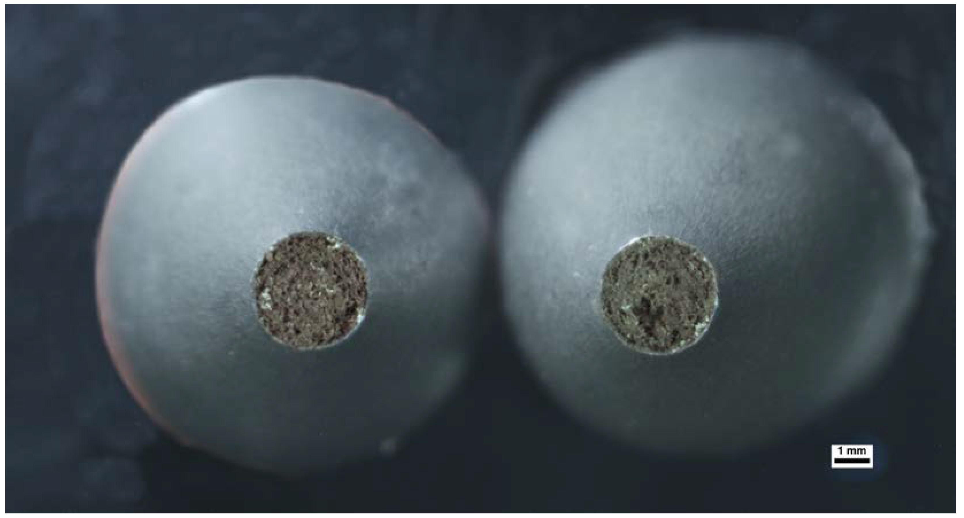
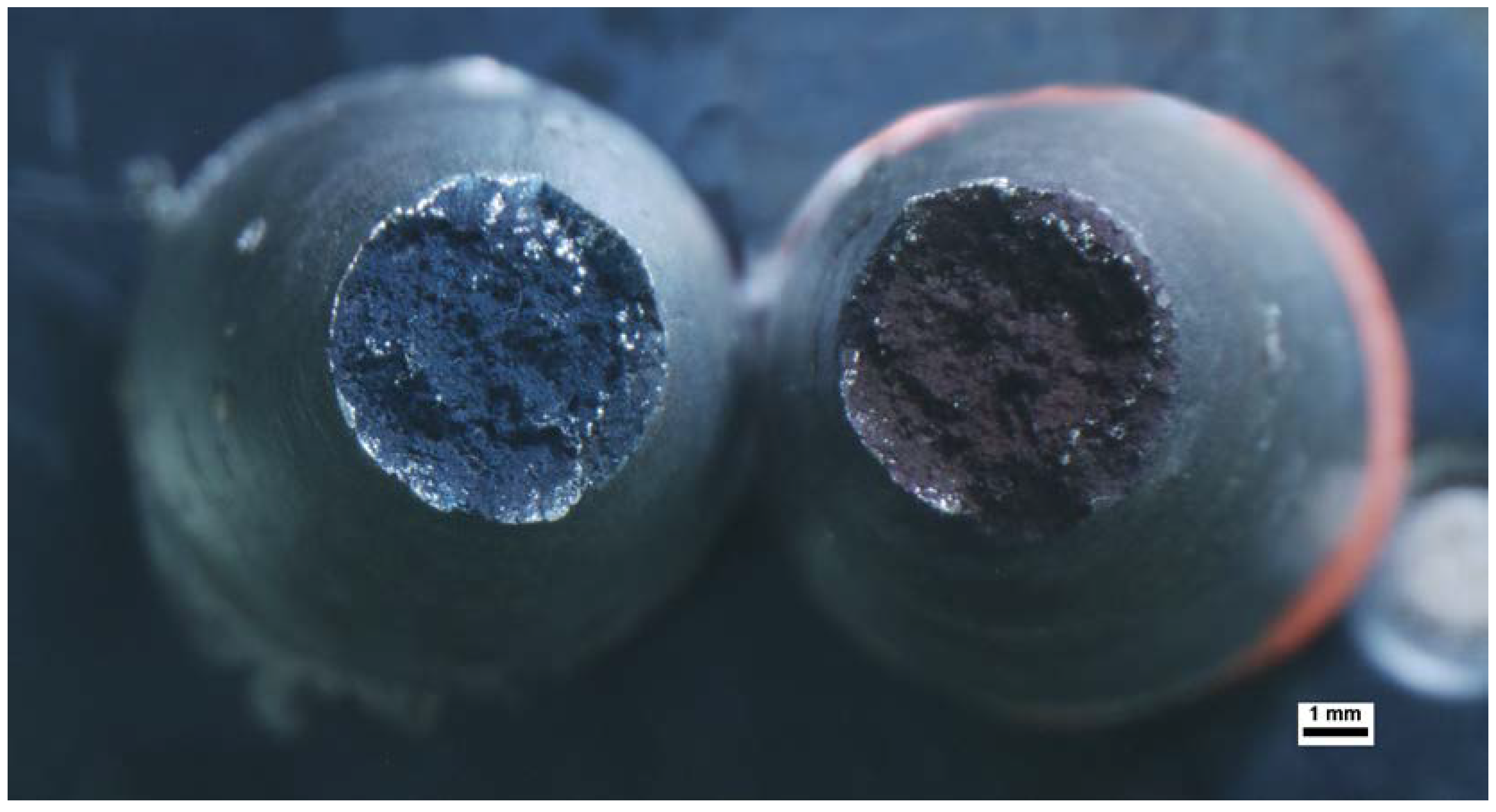
3.1. Results of Macroscopic Examinations

Figure 4 presents a view of selected samples (out of a total of 90) after the nil-strength test. Some of the samples exhibit necking, which may indicate plastic deformation (ductile fracture, e.g., NDT 2, DRT 3, H 2, C 1), while others show brittle fracture (e.g., NST 1, NDT 1, NST 3). Necking is clearly visible in Figure 4 as the points where the necked region forms during tension. Ductile fracture after extensive plastic deformation is characterized by slow defect/crack propagation. Brittle fractures occur along crystallographic (cleavage) planes and are characterized by rapid crack propagation.
Figure 4. View of selected samples after tearing under different conditions.
Metals 13 01633 g004

3.2. Results of the NST (Nil-Strength Test) Investigation

The fracture of the samples used for NST testing indicates a brittle fracture pattern. On the fractures shown in Figure 5, the presence of liquid metal can be observed, while the remaining area and the absence of necking indicate a brittle nature of the fracture. Sample necking does not occur, indicating the loss of steel plasticity at this temperature of 1375 °C (Table 2).
Figure 5. Fracture of NST 1 sample at a temperature of 1388 °C (evaluation of Solidus–Liquidus Temperature).
Metals 13 01633 g005

3.3. Results of the DRT (Ductility Recovery Temperature) Investigation

The fracture surfaces of the samples obtained as a result of the DRT test are shown in Figure 6, Figure 7 and Figure 8. The results of the static tensile test are presented in Table 3. No presence of liquid was observed during the test in any sample. Sample DRT 1 (Figure 6) is characterized by the lowest necking, elongation, and tensile strength. A significant plasticity decrease was noticed at a temperature of 1350 °C. As the testing temperature decreased (subsequently by 10 °C), samples DRT 2 (Figure 7) and DRT 3 (Figure 8) exhibited a formed neck (indicating necking—return of ductility).
Figure 6. Brittle fracture of DRT 1 sample fractured at a temperature of 1350 °C, with no presence of liquid phase, without ductility, no visible necking.
Metals 13 01633 g006
Figure 7. Ductile fracture of DRT 2 sample fractured at a temperature of 1340 °C.
Metals 13 01633 g007
Figure 8. Ductile fracture of DRT 3 sample fractured at a temperature of 1330 °C. Highly ductile fracture in which the specimen necks down to a point.
Metals 13 01633 g008

3.4. Results of the NDT (Nil-Ductility Temperature) Investigation

The fracture surfaces of the samples obtained as a result of the NDT test are shown in Figure 9 and Figure 10. The results of the static tensile test are presented in Table 4. No presence of liquid was observed during the test in any sample. NDT 1 (Figure 9) is characterized by the lowest necking, elongation, and tensile strength. A significant plasticity decrease was noticed at a temperature of 1360 °C. As the testing temperature decreased (to 1349 °C), sample NDT 2 (Figure 10) exhibited a formed neck (indicating necking—return of ductility).
Figure 9. Brittle fracture of NDT 1 sample fractured at a temperature of 1360 °C, with no presence of liquid phase, without ductility.
Metals 13 01633 g009
Figure 10. Ductile fracture of NDT 2 sample fractured at a temperature of 1349 °C, ductility deformation with visible necking.
Metals 13 01633 g010

3.5. Results of the Static Tensile Test at Various Temperatures Investigation

The tensile strength of steel changes with temperature due to microstructural processes occurring within specific temperature ranges. Generally, the tensile strength of steel decreases as the temperature rises. The soft and ductile nature of austenite leads to a decrease in tensile strength with increasing temperature in steels where it is the stable phase. As the temperature rises, atoms within the austenitic crystal lattice start moving faster, leading to a more relaxed lattice structure. This reduction in atom spacing due to temperature increase in X5CrNi18-10 steel results in a decrease in Young’s modulus and the elastic modulus. Consequently, the steel becomes more susceptible to deformation, causing a decrease in tensile strength, as shown in Figure 11, Figure 12 and Figure 13.
Static tensile tests were conducted while heating the samples at a rate of 50 °C/s at temperatures of 1200 °C (H 1), 1000 °C (H 2), and 800 °C (H 3). Additionally, inert cooling was performed from 1360 °C to temperatures of 1200 °C (C 1) and 800 °C (C 2), as indicated in Table 5. The static tensile tests on X5CrNi18-10 steel at temperatures of 800 °C (H 3), 1000 °C (H 2), and 1200 °C (H 1) revealed that the sample H 2 exhibited the lowest tensile strength of 145.9 MPa, which is lower than the result from sample H 1 (170.4 MPa). The presence of M23C6 carbides, which precipitate in the temperature range of 700–900 °C, might explain this lack of correlation. Their presence reduces the corrosion resistance of the steel, particularly its ductility, relative to increased tensile strength. Another mechanism potentially contributing to increased tensile strength in the sample could be austenite grain growth. Furthermore, upon heating the sample to 1360 °C and subsequently cooling it to 1200 °C and 800 °C, there was an increase in tensile strength, along with decreasing temperature. At 1360 °C, the M23C6 carbides dissolved. The sequence of sample fractures is depicted in Figure 14 and Figure 15.
Figure 11. Ductile fracture of specimen H 1 tested during heating, fractured at a temperature of 1200 °C. Highly ductile fracture in which the specimen necks down to a point.
Metals 13 01633 g011
Figure 12. Ductile fracture of specimen H 2 tested during heating, fractured at a temperature of 1000 °C.
Metals 13 01633 g012
Figure 13. Ductile fracture of specimen H 3 tested during heating, fractured at a temperature of 800 °C. Moderately ductile fracture after some necking, cup and cone surfaces.
Metals 13 01633 g013
Figure 14. Ductile fracture of specimen C 1 tested during cooling, fractured at a temperature of 1200 °C.
Metals 13 01633 g014
Figure 15. Ductile fracture of specimen C 2 tested during cooling, fractured at a temperature of 800 °C.
Metals 13 01633 g015

3.6. Results of the Static Tensile Test at Various Temperatures Investigation

The microscopic examination reveals damaged structures and defects that result from using different temperature simulations. The resultant surfaces were inspected using visual methods. In the case of austenitic steel fractures examined using SEM microscopy at high magnification, the difference between NST samples (Figure 16) and H 3 (Figure 17), NDT (Figure 18), or DRT (Figure 19) is evident. To describe the damage evolution during plastic deformation and predict ductile fracture, several indicators related to voids have been studied and used to model fracture. Scanning Electron Microscope (SEM) results show detailed microstructures of the examined samples. Grain size was measured using a SEM microscope. The grain diameter varied in individual samples. The provided measured sizes under the description of the figures are average values. The surface of NST samples appears to be composed of partially melted crystals that underwent partial melting (in the temperature range between solidus and liquidus), and the remaining samples exhibit plastic deformation. The SEM images reveal a structure containing craters, pores, and a plastic character of cracking in the material. These findings provide valuable insights into the change in mechanical properties of the material at high temperatures. Sample NST 1 (Figure 16) exhibits brittle cracking visible earlier in Figure 4 (without necking) and Figure 5, with partially melted crystals visible in the SEM image (Figure 16); however, this is not a typical brittle fracture. At a high temperature of 1375 °C (NST), AISI 304 steel loses its ductility due to a liquid film in the form of droplets surrounding the alloy crystals. These material properties determine its susceptibility to hot cracking, loss of ductility during welding, casting, or plastic processing, and consequently, material continuity.
Figure 16. Fracture of NST 1 sample at a temperature of 1388 °C. Evaluation of Solidus Temperature. Fracture behaviors of the samples with different mean grain sizes of 19 μm.
Metals 13 01633 g016
Figure 17. Ductile fracture of H 3 sample during heating, at a temperature of 800 °C. Fracture behaviors of the samples with different mean grain sizes of 3 μm.
Metals 13 01633 g017
Figure 18. Ductile fracture of NDT 2 sample at a temperature of 1349 °C, ductility deformation with visible necking. Fracture behaviors of the samples with different mean grain sizes of 5 μm.
Metals 13 01633 g018
Figure 19. Ductile fracture of DRT 2 sample at a temperature of 1340 °C. Fracture behaviors of the samples with different mean grain sizes of 22 μm.
Metals 13 01633 g019

4. Discussion

The high-temperature tensile tests carried out in the Gleeble 3500 thermomechanical simulator also allowed us to determine the nil-strength temperature (NST), the nil-ductility temperature (NDT), the ductility recovery temperature (DRT), and the high-temperature brittleness range (HTBR) of the tested steel.
To find the lower limit of the HTBR during cooling, successive samples were examined by heating them to a temperature 5 °C lower than the zero-strength temperature (NST) and then cooling them to the specified temperature. As a result of the investigation, it was found that the NST temperature is 1375 °C. Once the temperature was reached, the samples were elongated at that temperature, and their percentage necking and percentage elongation were measured to determine the loss. It is generally accepted that the lower limit of the high-temperature brittleness range occurs at a relative necking of 5%. After analyzing the samples, it can be estimated that the DRT is slightly below 1350 °C. This temperature was adopted as the lower limit of the HTBR during cooling.
To find the lower limit of the temperature brittleness range during heating, the samples were heated to a specific temperature and then elongated. The elongated samples were measured, and their percentage necking and percentage elongation were calculated. When estimating the nil-ductility temperature (NDT), the same guidelines as those used in testing for the return-to-ductility temperature (DRT) are applied. This means that when the necking is around 5%, it indicates the nil-ductility temperature. The results suggest that the nil-ductility temperature (NDT) is close to 1360 °C.
Knowledge of the NST and NDT temperatures allows for the determination of a steel’s susceptibility to cracking. It is generally accepted that when the condition NST—NDT < 20 °C is met, cracks in steel essentially do not occur. Based on the knowledge of the NST and DRT temperatures, it is possible to determine the high-temperature brittleness range (HTBR) (HTBR = NST − DRT) [37]. Analyzing the research findings, it can be stated that the HTBR is 15 °C during heating (HTBR = NST − NDT) and 25 °C during cooling (HTBR = NST − DRT). These ranges are relatively narrow, indicating significant resistance to hot cracks during welding.
The resistance of the austenitic steel X5CrNi18-10 to tensile strength at elevated temperatures was also investigated. These tests were conducted during heating and cooling. Comparing samples based on the cycle, it can be stated that samples that were immediately elongated exhibited higher mechanical properties. The discrepancy is more pronounced at 800 °C compared to 1200 °C. At 800 °C, the stresses required to rupture the samples were significantly higher than at higher temperatures. During the test at 1000 °C, there was likely a measurement error, resulting in results suggesting a reduction in strength or a high-temperature ferrite-to-austenite phase transformation. This phenomenon would require further investigation.
Upon examining the samples, a relationship can also be observed between the fracture patterns of the samples and the temperature at which they were tested. Starting from the zero-strength temperature (NST), it can be observed that they fractured in a completely brittle manner, followed by fractures gradually showing increasing necking. The largest necking was obtained when testing the sample during heating and elongation at 1349 °C, as well as during cooling and elongation of samples at 1200 °C. This may indicate high material plasticity at these temperatures.
Based on the values obtained, the high-temperature brittleness range (HTBR) and the hot cracking resistance index were determined. Fracture examinations were conducted in order to describe the cracking mechanisms. It was found that the main cracking mechanism was the partial melting of grains and, subsequently, the rupture of a thin liquid film along crystal boundaries as a result of deformation during crystallization. Understanding how material ductility changes within various temperature ranges and its implications for behavior during deformation and welding processes is crucial in studying this mechanism [20,22].

5. Conclusions

The research aimed to assess the susceptibility of X5CrNi18-10 steel to the formation of crystallization cracks and to determine the high-temperature brittleness range, which is closely associated with the propensity for the occurrence of these cracks. Conducted tests have enabled the determination of the high-temperature brittleness range HTBR (High-Temperature Brittleness Range) of X5CrNi18-10 steel, understood as the difference value temperature between the temperature NST (Nil-Strength Temperature) and the ductility recovery temperature DRT (Ductility Recovery Temperature). The research and discussion in this paper demonstrate that the paper’s objective of proving steel’s ability to withstand hot cracks has been achieved. The weldability of X5CrNi18-10 is determined by the high-temperature brittleness range, HTBR, which is determined by the heat treatment of this steel. It can be concluded that X5CrNi18-10 steel is likely to resist hot cracking during welding. The fracture tendency of the tested austenitic stainless steel X5CrNi18-10 during tensile tests was determined by conducting experiments in the Gleeble 3500 thermomechanical simulator. The development of welding conditions and predicted mechanical properties may be based on this steel and the determined characteristics of plastic deformation processes at high temperatures. To confirm if the Ductility Dip Cracking (DDC) mechanism is present in the studied material, additional fractographic studies should be carried out. The industry frequently uses materials that are prone to hot cracking during welding. It is necessary to consider the susceptibility and propensity of welded joints to hot cracking in order to maintain their appropriate quality.
The obtained research results will contribute to a better understanding of phenomena occurring at high temperatures in austenitic stainless steel, primarily the decrease in strength to zero. In practice, this will translate into more efficient welding technology planning (linear welding energy, preheating temperature, and inter-pass temperature).

Author Contributions

Conceptualization, S.J.K.; methodology, S.J.K.; software, W.G.; validation, K.U. and S.J.K.; formal analysis, S.J.K., W.G. and K.U.; investigation, W.G.; resources, S.J.K.; data curation, W.G.; writing—original draft preparation, S.J.K.; writing—review and editing, S.J.K. and K.U.; visualization, W.G.; supervision, S.J.K. and K.U.; project administration, S.J.K. All authors have read and agreed to the published version of the manuscript.

Funding

This research received no external funding.

Data Availability Statement

All experimental data are available from the corresponding author by request.

Acknowledgments

The authors would like to thank Agnieszka Kochmańska from West Pomeranian University of Technology in Szczecin for her help in carrying out research using the Scanning Electron Microscope (SEM).

Conflicts of Interest

The authors declare no conflict of interest.

Appendix A

Appendix A.1. Preparation of X5CrNi18-10 Steel Samples

  • A 10 mm diameter rod was cut into 120 mm lengths using a band saw and machined.
  • Threads were tapped onto the cut rods to a length of 15 mm.
  • The samples were degreased using acetone.
  • The length and diameter of the samples were measured using a Limit brand caliper with a measurement range of 150 mm and an accuracy of ±0.03 mm.
  • R-type thermocouples were attached to the samples using a Gleeble Thermocouple welder (thermocouples of the R type are utilized for investigating high temperatures up to 1500 °C; they consist of platinum and rhodium).
  • Locking nuts were placed on the threaded samples in copper holders to prevent sample movement during testing.
  • The samples were placed in the copper holders and inserted into the Gleeble 3500 machine.
  • Next, the thermocouples were connected to the control console, and the machine doors were closed.

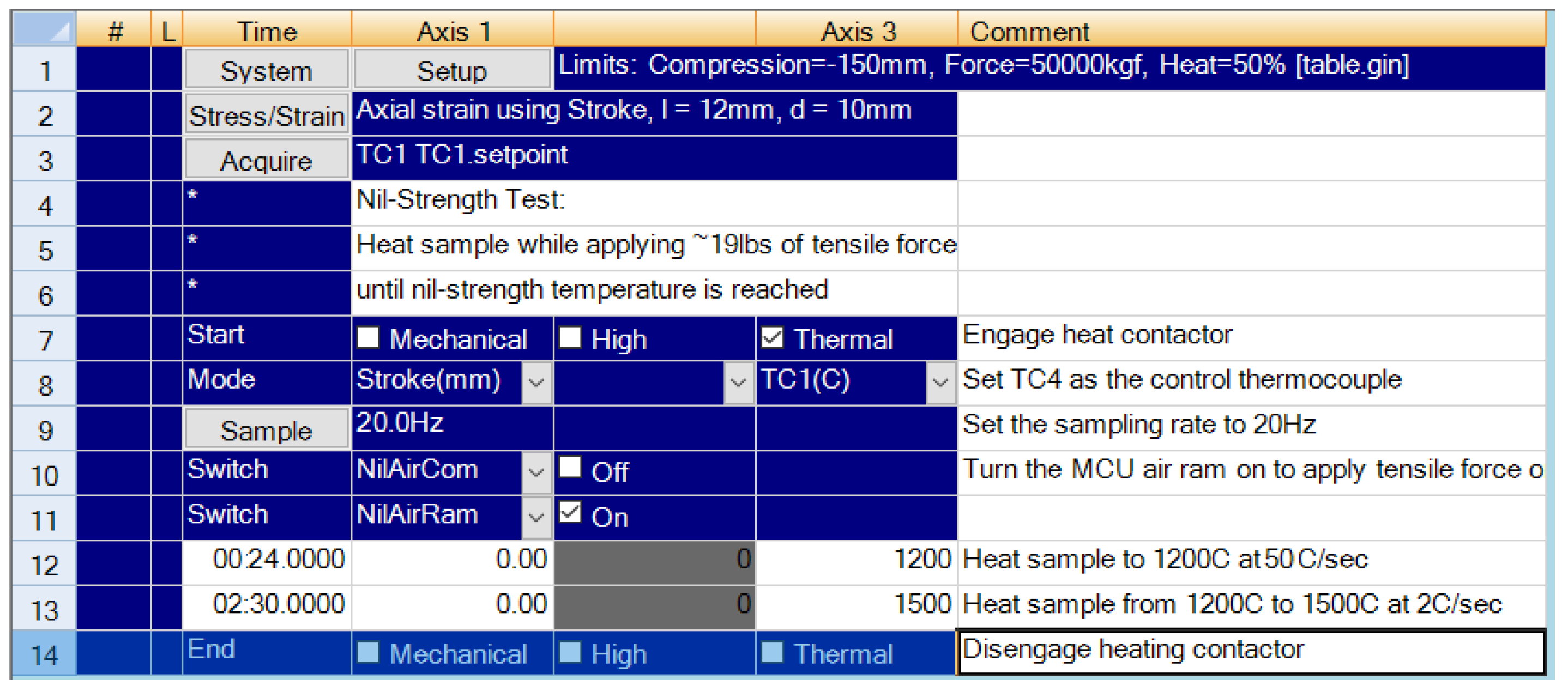
Appendix A.2. Nil-Strength Temperature (NST) Testing

  • The samples were preloaded pneumatically with a force of 0.1 kN.
  • The testing was conducted under a high vacuum achieved by operating a vacuum pump and a diffusion pump to reach 1 × 10⁻⁶ torr.
  • After achieving vacuum conditions, the pre-written program was initiated and confirmed on the machine.
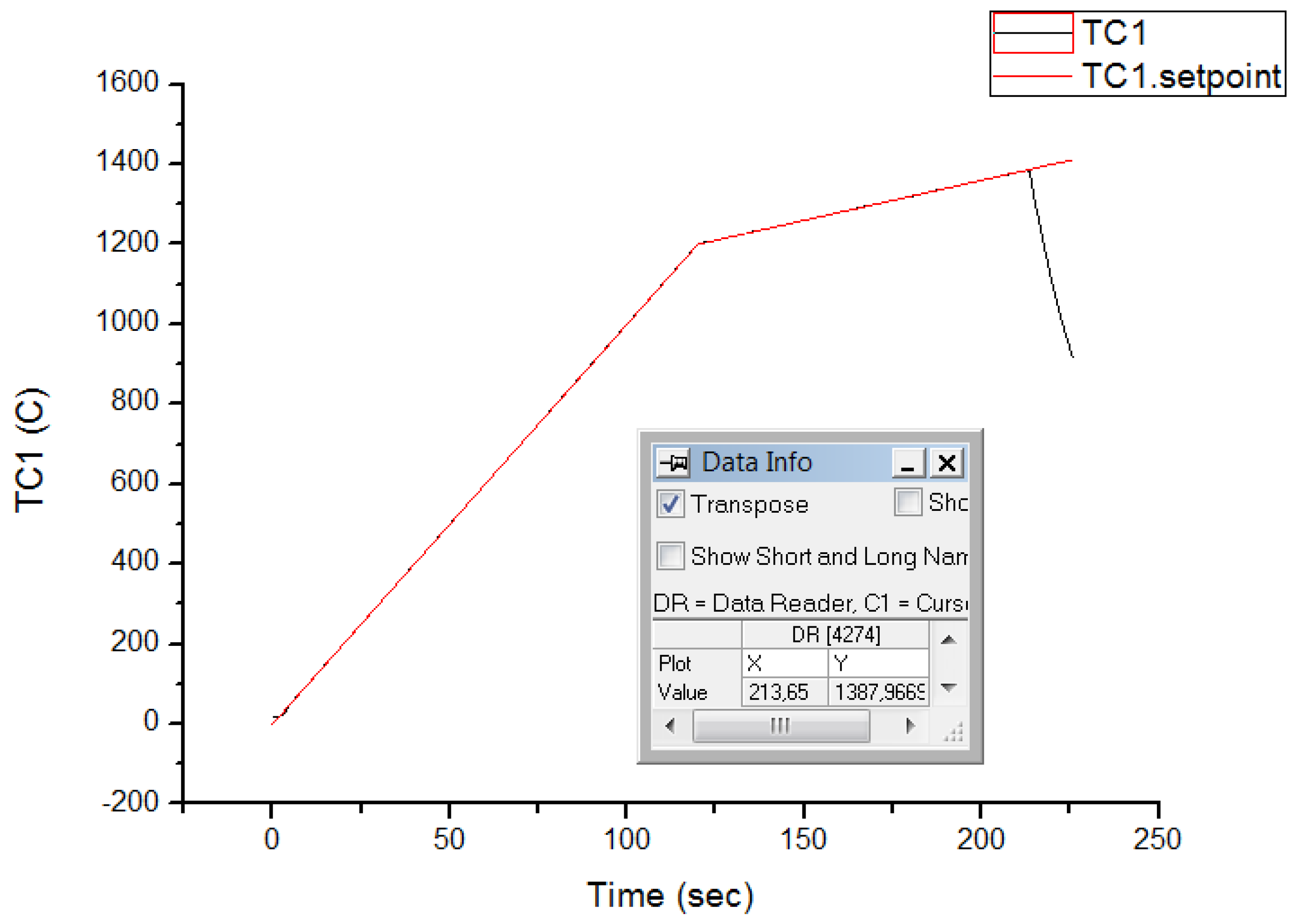
  • The sample was heated at a rate of 50 °C/s to 1200 °C, followed by a pause at the 2 °C/s heating rate.
  • After the sample ruptured (Figure 3), air was introduced, thermocouples were disconnected, and the sample was removed.
  • The obtained results were then recorded.

Appendix A.3. NDT Testing

  • The sample for NDT testing was pneumatically loaded, and the tensioning force was deactivated.
  • Air was evacuated (just like in Appendix A.2. points 1 and 2), and the program was activated.
  • The sample was heated to the designated temperature (1360 °C, 1350 °C) and then elongated hydraulically at a rate of 50 mm/s.
  • After the sample ruptured, air was introduced into the testing chamber, thermocouples were disconnected, and the sample was removed.
  • The length and necking at the rupture point were measured.

Appendix A.4. DRT Testing

  • The sample was pneumatically loaded, and the tensioning force was deactivated.
  • Air was evacuated (just like in Appendix A.2. points 1 and 2), and the program was activated.
  • The sample was heated to 1370 °C at a rate of 50 °C/s and then cooled at a rate of 10 °C/s to the desired temperature (1350 °C, 1340 °C, 1330 °C).
  • After reaching the target temperature, the sample was hydraulically elongated at a rate of 50 mm/s.
  • After rupture, the vacuum was deactivated, thermocouples were disconnected, and the ruptured sample was extracted.
  • The length and necking of the sample were measured, and the data were recorded.

References

  1. Kurc-Lisiecka, A.; Ozgowicz, W.; Kalinowska-Ozgowicz, E.; Maziarz, W. The Microstructure of Metastable Austenite in X5CrNi18-10 Steel after its Strain-Induced Martensitic Transformation. Mater. Tehnol. Mater. Technol. 2016, 50, 837–843. [Google Scholar] [CrossRef]
  2. Romanowski, M.; Łukianowicz, C.; Sutowska, M.; Zawadka, W.; Pimenov, D.Y.; Nadolny, K. Assessment of the Technological Quality of X5CrNi18-10 Steel Parts after Laser and Abrasive Water Jet Cutting Using Synthetic Index of Technological Quality. Materials 2021, 14, 4801. [Google Scholar] [CrossRef]
  3. Siddique, A.G.; Vijaya, R.B.; Elanchezhian, C.; Siddhartha, D.; Ramanan, N. Analysis of The Friction Welding Mechanism of Low Carbon Steel–Stainless Steel and Aluminium—Copper. Mater. Proc. 2019, 16, 766–775. [Google Scholar] [CrossRef]
  4. Sawa, M.; Szala, M.; Henzler, W. Innovative Device for Tensile Strength Testing of Welded Joints: 3D Modelling, FEM Simulation and Experimental Validation of Test Rig—A Case Study. Appl. Comput. Sci. 2021, 17, 92–105. [Google Scholar] [CrossRef]
  5. Grzejda, R.; Parus, A.; Kwiatkowski, K. Experimental studies of an asymmetric multi-bolted connection under monotonic loads. Materials 2021, 14, 2353. [Google Scholar] [CrossRef] [PubMed]
  6. Grzejda, R. Thermal strength analysis of a steel bolted connection under bolt loss conditions. Eksploat. Niezawodn. Maint. Reliab. 2022, 24, 269–274. [Google Scholar] [CrossRef]
  7. Macek, W.; Pejkowski, Ł.; Branco, R.; Nejad, R.M.; Żak, K. Fatigue fracture surface metrology of thin-walled tubular austenitic steel specimens after asynchronous loadings. Eng. Fail. Anal. 2022, 138, 106354. [Google Scholar] [CrossRef]
  8. Walczak, M.; Szala, M.; Okuniewski, W. Assessment of Corrosion Resistance and Hardness of Shot Peened X5CrNi18-10 Steel. Materials 2022, 15, 9000. [Google Scholar] [CrossRef]
  9. Kurc-Lisiecka, A.; Lisiecki, A. Laser welding of stainless steel. J. Achiev. Mater. Manuf. Eng. 2020, 98, 32–40. [Google Scholar] [CrossRef]
  10. Evin, E.; Tomáš, M. Formability Prediction of Laser-Welded Stainless Steel AISI 304 and AISI 430. Metals 2022, 12, 54. [Google Scholar] [CrossRef]
  11. Pańcikiewicz, K.; Świerczyńska, A.; Hućko, P.; Tumidajewicz, M. Laser Dissimilar Welding of AISI 430F and AISI 304 Stainless Steels. Materials 2020, 13, 4540. [Google Scholar] [CrossRef] [PubMed]
  12. Ye, Y.; Yang, B.; Yang, Y.; Pan, Z.; Chen, C.; Zhang, X. Research on the Formation, Microstructure, and Properties of 304 Stainless Steel AC-DC Hybrid TIG Welding. Metals 2023, 13, 1127. [Google Scholar] [CrossRef]
  13. Adamiec, J. Assessment of High-Temperature Brittleness Range of the Casted Alloy AZ91. MSF 2011, 690, 41–44. [Google Scholar] [CrossRef]
  14. Tomków, J.; Landowski, M.; Rogalski, G. Application Possibilities of the S960 Steel in Underwater Welded Structures. Facta Univ. Ser. Mech. Eng. 2022, 20, 199–209. [Google Scholar] [CrossRef]
  15. Tomków, J.; Świerczyńska, A.; Landowski, M.; Wolski, A.; Rogalski, G. Bead-on-Plate Underwater Wet Welding on S700MC Steel. Adv. Sci. Technol. Res. J. 2021, 15, 288–296. [Google Scholar] [CrossRef] [PubMed]
  16. John, B.; Maqbool, F.; Kowerko, D.; Buhl, J.; Härtel, S.; Hensel, J. Modification of the weld penetration characteristics in laser deep welding by the use of instationary gas flows. J. Appl. Eng. Des. Simul. 2022, 2, 22–38. [Google Scholar] [CrossRef]
  17. Kusmič, D.; Cech, O.; Klakurková, L. Corrosion Resistance of Plasma Nitrided Austenitic Stainless Steel AISI 304 (X5CrNi18-10). ECS Trans. 2020, 99, 231–239. [Google Scholar] [CrossRef]
  18. Poláková, N.; Dostál, P. Titanium and Stainless Steel MIG LSC Welding. Acta Technol. Agric. 2019, 22, 56–59. [Google Scholar] [CrossRef]
  19. Ziewiec, A. Study of the Weldability of Austenitic PH Steel for Power Plants. Arch. Metall. Mater. 2016, 61, 1109–1114. [Google Scholar] [CrossRef]
  20. Yu, P.; Morrow, J.; Kou, S. Resistance of austenitic stainless steels to ductility-dip cracking: Mechanisms. Weld. J. 2021, 100, 291–301. [Google Scholar] [CrossRef]
  21. Mohamed, M.S.; Abtan, A.A.; Moosa, A.U. Microstructure and Mechanical Properties Assessments of 304 Austenitic Stainless Steel and Monel 400 Dissimilar GTAW Weldment. J. Compos. Adv. Mater. Rev. Compos. Matériaux Avancés 2023, 33, 135–144. [Google Scholar] [CrossRef]
  22. Nissley, N.E.; Lippold, J.C. Ductility-Dip Cracking Susceptibility of Nickel-Based Weld Metals Part 1: Strain-to-Fracture Testing. Weld. J. 2008, 87, 257–264. [Google Scholar]
  23. Nam, T.H.; An, E.; Kim, B.J.; Shin, S.; Ko, W.S.; Park, N.; Kang, N.; Jeon, J.B. Effect of Post Weld Heat Treatment on the Microstructure and Mechanical Properties of a Submerged-Arc-Welded 304 Stainless Steel. Metals 2018, 8, 26. [Google Scholar] [CrossRef]
  24. Kiss, I.; Alexa, V. Study on Deformation Behavior of Non–Hardenable Austenitic Stainless Steel (Grade X5CrNi18–10) by Hot Torsion Tests. Teh. Glas. 2020, 14, 396–402. [Google Scholar] [CrossRef]
  25. Kciuk, M.; Lasok, S. Corrosion Resistance of X5CrNi18-10 Stainless Steel. Arch. Metall. Mater. 2017, 62, 2101–2106. [Google Scholar] [CrossRef]
  26. Wierzbowska, K.; Kochmańska, A.E.; Kochmański, P. Resistance of Aluminide Coatings on Austenitic Stainless Steel in a Nitriding Atmosphere. Materials 2022, 15, 162. [Google Scholar] [CrossRef]
  27. Saternus, Z.; Piekarska, W.; Kubiak, M.; Domański, T. The Influence of Welding Heat Source Inclination on the Melted Zone Shape, Deformations and Stress State of Laser Welded T-Joints. Materials 2021, 14, 5303. [Google Scholar] [CrossRef]
  28. Ridha Mohammed, G.; Ishak, M.; Ahmad, S.N.A.S.; Abdulhadi, H.A. Fiber Laser Welding of Dissimilar 2205/304 Stainless Steel Plates. Metals 2017, 7, 546. [Google Scholar] [CrossRef]
  29. Wang, J.; Peng, F.; Zhou, L.; Luo, Y.; Zhang, W.; Wu, Z. High-Strength Ductility Joining of Multicomponent Alloy to 304 Stainless Steel Using Laser Welding Technique. Materials 2023, 16, 2374. [Google Scholar] [CrossRef]
  30. Adamiec, J. Assessment of the Hot-Cracking Susceptibility of Welded Joints of the 7CrMoVTiB10-10 Bainitic Steel Used in Heat Exchangers. Energies 2023, 16, 162. [Google Scholar] [CrossRef]
  31. Kawulok, P.; Schindler, I.; Smetana, B.; Moravec, J.; Mertová, A.; Drozdová, Ľ.; Kawulok, R.; Opěla, P.; Rusz, S. The Relationship between Nil-Strength Temperature, Zero Strength Temperature and Solidus Temperature of Carbon Steels. Metals 2020, 10, 399. [Google Scholar] [CrossRef]
  32. Kawulok, R.; Schindler, I.; Navrátil, H.; Ševčák, V.; Sojka, J.; Konečná, K.; Chmiel, B. Hot Formability of Heat-Resistant Stainless Steel X15CrNiSi 20-12. Arch. Metall. Mater. 2020, 65, 727–734. [Google Scholar] [CrossRef]
  33. Fojt-Dymara, G.; Opiela, M.; Borek, W. Susceptibility of High-Manganese Steel to High-Temperature Cracking. Materials 2022, 15, 8198. [Google Scholar] [CrossRef]
  34. Kuzsella, L.; Lukács, J.; Szűcs, K. Nil-strength temperature and hot tensile tests on S960QL high-strength low-alloy steel. Prod. Process. Syst. 2012, 6, 67–78. [Google Scholar] [CrossRef]
  35. Turowska, A.; Adamiec, J.; Rzychoń, T. Technology of repairing QE22 alloy casts. Arch. Metall. Mater. 2014, 59, 667–673. [Google Scholar] [CrossRef]
  36. Łyczkowska, K.; Adamiec, J. The Phenomena and Criteria Determining the Cracking Susceptibility of Repair Padding Welds of the Inconel 713C Nickel Alloy. Materials 2022, 15, 634. [Google Scholar] [CrossRef]
  37. Zalecki, W.; Wrożyna, A.; Łapczyński, Z.; Molenda, R. Influence of Microstructure on Some Properties of AHSS Steels. Pr. Inst. Metal. Żelaza 2016, 68, 19–25. [Google Scholar]
Figure 1. High-temperature brittleness range [30].
Metals 13 01633 g001
Figure 2. Window of the Nil-Strength Test Program in the Gleeble 3500 System.
Metals 13 01633 g002
Figure 3. Fracture point determination chart.
Metals 13 01633 g003
Table 1. Measured and nominal chemical composition of X5CrNi18-10 (AISI 304) stainless steel (mas. %).
CMnSiPSCrNiFe
PN-EN 10088-2:2014-12max 0.030max 2.00max 0.75max 0.045max 0.01517.5–19.508.00–10.50bal.
X5CrNi18-10 (1)0.0271.5510.3750.0340.00218.179.35bal.
(1) Results of spectrometer analysis on Leco GDS500A.
Table 2. Results of the NST (Nil-Strength Test) investigation.
NST
Specimen No.Temperature [°C]Preload Stress [kN]Average
NST 113880.11375 °C
NST 213580.11
NST 313780.09
Table 3. Results of the DRT (Ductility Recovery Temperature) investigation.
DRT
Specimen No.Temp. [°C]L0 [mm]Lu [mm]d0 [mm]du [mm]S0 [mm2]A [%]Z [%]F
[N]
Rm [MPa]
DRT 11350121.06122.1110.019.8385.420.873.56260.304
DRT 21340121.37126.679.987.0984.914.1849.531251.472
DRT 31330121.25129.299.964.3584.576.2280.932553.016
Table 4. Results of the NDT (Nil-Ductility Temperature) investigation.
NDT
Specimen No.Temp. [°C]L0 [mm]Lu [mm]d0 [mm]du [mm]S0 [mm2]A [%]Z [%]F
[N]
Rm [MPa]
NDT 11360121.51122.119.989.9284.910.491.250.059
NDT 21349121.6131.39.953.4284.47.3988.2100.118
Table 5. Results of the static tensile test at various temperatures investigation.
Tensile Strength Testing during Heating
Specimen No.Temp. [°C]L0 [mm]Lu [mm]d0 [mm]du [mm]S0 [mm2]A [%]Z [%]F [N]Rm [MPa]
H 11200121.73126.959.985.8884.914.1165.2914,470170.4
H 21000121.36130.759.954.5684.47.187912,313145.9
H 3800121.44127.289.965.7684.574.5966.5629,365347.2
Tensile strength testing during cooling
C 11200121.47132.1210.032.9185.778.0191.58807494.1
C 2800121.95126.919.997.8485.083.9138.4116,497193.9
Disclaimer/Publisher’s Note: The statements, opinions and data contained in all publications are solely those of the individual author(s) and contributor(s) and not of MDPI and/or the editor(s). MDPI and/or the editor(s) disclaim responsibility for any injury to people or property resulting from any ideas, methods, instructions or products referred to in the content.

