
Understanding the Effect of Substrate Preheating Temperature and Track Spacing on Laser Assisted Cold Spraying of Ti6Al4V


1
Surface, Corrosion and Interface Engineering, TWI Ltd., Cambridge CB21 6AL, UK
2
Faculty of Engineering, Environment and Computing, Coventry University, Coventry CV1 5FB, UK
3
Materials Innovation Centre, School of Engineering, University of Leicester, Leicester LE1 7RH, UK
*
Author to whom correspondence should be addressed.
Metals 2023, 13(10), 1640; https://doi.org/10.3390/met13101640
Submission received: 8 August 2023
/
Revised: 11 September 2023
/
Accepted: 20 September 2023
/
Published: 25 September 2023
(This article belongs to the Special Issue Modern Cold Spray Technique (Volume II))
Abstract
:In this study, laser-assisted cold spray (LACS) of titanium alloy Ti6Al4V onto Ti6Al4V substrates has been investigated in two phases: (i) single-track deposits on substrates preheated to 400 °C, 600 °C, and 800 °C, respectively, and (ii) single-layer (multi-track) deposits on substrates preheated to 600 °C with three different track spacings (1 mm, 2 mm, and 3 mm). Cross-sectional microstructures of the single-track deposits showed intimate contact at the interfaces, especially extensive interfacial mixing for specimens with substrate preheating at 600 °C and 800 °C. Cross-sectional area porosity content in single layer LACS coatings was found to be around 0.4%, which is significantly lower than the standard or conventional cold spray (CS) process having ~2.3% porosity. The microstructure reveals that the LACS process has improved the adhesion and cohesion of the deposits, in addition to the other advantages of the CS process. The average microhardness values of LACS deposits were found to be in the range of 388–403 HV (the highest hardness with the lowest track spacing), which is approximately 6–10% lower than that of the CS deposits without laser substrate preheating. Tensile residual stresses were found in all three LACS coatings, which was due to elevated process gas temperature along with high heat input during laser preheating of the substrate. It was observed that the higher the track spacing, the higher the stress magnitude, i.e., 31 MPa, 135 MPa, and 191 MPa in the longitudinal direction when deposited with 1 mm, 2 mm, and 3 mm track spacings, respectively. Heat treatments induced varied microstructures in LACS coatings, encompassing fully equiaxed or lamellar α-phase within the β-phase, or a bimodal microstructure, with characteristics linked to track spacing variations. Key contributions of this study include enhanced coating-substrate adhesion through extensive interfacial mixing, a substantial reduction in cross-sectional area porosity compared to CS, insights into the effects of residual stresses, and, ultimately, advancing the comprehension of LACS and its potential advantages over conventional CS process.
1. Introduction
Cold spray (CS) technology is a solid-state material deposition technique wherein powder particles are accelerated to reach a critical velocity by a supersonic jet of preheated compressed gas (usually N2 and/or He). The high-velocity impact of the sprayed particles on a substrate and associated severe plastic deformation disrupt thin oxide films promoting intimate metallic contact of particles and substrate by creating bonding similar to explosive welding (or explosive bonding), resulting in solid-state deposition of material layers. The ability of CS technology to use lower deposition temperature (always below the melting point of the deposited material) makes it suitable for depositing temperature-sensitive materials, such as nanocrystalline and amorphous materials, as well as oxygen-sensitive materials such as titanium, aluminium, copper, etc. [1,2,3].
CS technology is becoming increasingly popular as a potentially viable tool for repairing/remanufacturing high-value structural components. Over the recent years, CS has also been adopted for solid-state additive manufacturing applications, known as cold spray additive manufacturing (CSAM) [4,5]. However, for some high-strength alloys, such as titanium alloy Ti6Al4V, it has been a challenge to achieve fully dense and well-bonded deposits that are suitable for structural applications.
There is a growing demand for Ti6Al4V alloy for various industrial applications, particularly in the aerospace sector, due to its well-known chemical, physical, and mechanical properties [6]. Feedstock powders of Ti6Al4V are often produced via gas or plasma atomisation and as such, microstructures comprise fine grained, martenstic phase structures, which limit sufficient deformation for adequate bonding upon impact. Moreover, the bonding mechanism involved in the CS process is predominantly mechanical interlocking rather than metallurgical bonding, although there is some evidence of the latter which is manifested by localised adiabatic transient interfacial melting. Consequently, the resulting metallurgical and mechanical properties of the CS Ti6Al4V deposits are not adequate for load-bearing structural applications in the as-deposited condition. Post-deposition thermal treatments can significantly improve the static mechanical properties. However, fully dense deposits with desired elongation cannot be achieved using standard thermal treatment processes such as annealing, solution treatment and ageing (STA), and even hot isostatic pressing (HIP). Although, there were a few exceptions where properties similar to the wrought material were achieved using encapsulated-HIP treatment [7,8].
In laser-assisted cold spray (LACS), in-situ laser substrate preheating is used to create transient heating regions on the substrate ahead of impinging spray particles [9,10,11]. Some limited studies have shown that both deposition behaviour and mechanical integrity of the deposited material can be enhanced by combining standard CS with laser processing techniques. Laser substrate preheating induces substrate softening and enables better shear localisation when both the impacting powder and substrate co-deform in an approximately equal manner. Consequently, this approach has yielded superior bonding and enhanced deposit properties with minimal microstructural alterations to the substrate and feedstock powder [9,10,11]. LACS can potentially open up many opportunities for depositing traditionally difficult-to-spray alloys. The recent advancement of LACS [12,13] is promising for improving the characteristics (porosity, adhesion, cohesion, etc.) of high-strength alloy CS deposits such as Ti6Al4V. Perton et al. [14] have studied the individual and cumulative effects of in-situ pulsed laser ablation (PLA) and continuous laser pre-heating on the adhesion and cohesion of CS Ti6Al4V deposits (N2 as the process gas at 800 °C and 4 MPa). Using the PLA process alone before CS led to a smooth surface resulting in improved adhesion. However, a drop of cohesion and adhesion was observed when PLA was maintained throughout the CS process, i.e., in between the deposited layers. Nevertheless, the laser pre-heating (25 °C, 120 °C, and 200 °C) combined with the PLA process found to be beneficial in improving coating adhesion and cohesion. Birt et al. [15] have performed a study on statistically guided development for microstructural control of LACS Ti6Al4V (N2 as the process gas at 550 °C and 3–4 MPa). They have achieved less than 1% porosity for Ti6Al4V coatings with a laser preheating surface temperature recorded upto 900 °C. Additionally, the thermomechanical treatment during LACS allowed controlled formation of secondary phases and morphologies [15]. LACS of other alloys found in literature include, pure Ti [10], Al alloys [16,17,18], Al + Al2O3 [19], Al-Cu [20], Al-12 wt.%Si [21], Ni-20Cr [17], In718 [12], SS 15-5 PH [22], AISI 4340 steel [23], high entropy alloy (HEA) CrMnCoFeN [24], NiCoCrAlYHfSi [25], oxide dispersion strengthened (ODS) steel alloy Fe-Ni-Zr [26,27,28], bio-ceramic Ti-HAP [29], etc.
In this study, a comprehensive investigation of LACS deposition trials was undertaken, wherein gas atomised Ti6Al4V powder was deposited onto Ti6Al4V substrates. LACS trials were carried out in two phases, exploring the influence of laser preheating and track spacing on LACS deposits. In Phase 1, single-track deposition trials were carried out on substrates preheated to 400 °C, 600 °C, and 800 °C, respectively, revealing the effects of laser preheating. In Phase 2, single-layer (multi-track) deposition trials were performed on substrates preheated to 600 °C, a temperature down-selected from Phase 1. Furthermore, the impact of three distinct track spacings: 1 mm, 2 mm, and 3 mm were explored. LCAS deposits were characterised in terms of surface profilometry, microstructure, porosity, phase analysis using X-ray diffraction, microhardness, and residual stress. The findings of this study provide insights into the optimisation LACS process for depositing titanium alloy Ti6Al4V, offering the potential for substantial advancements over conventional CS, which have not been thoroughly explored in previous literature.
2. Materials and Methods
2.1. Feedstock Powder and Substrate Material
A commercially available gas atomised Ti6Al4V alloy (grade 5) powder, with spherical morphology, was used. The particle size distribution, morphology, and cross-sectional microstructure of the feedstock powder are shown in Figure 1a–c, respectively. Particle size distribution was measured using laser diffraction particle size analyser (Malvern Mastersizer 2000, v5.60), following ASTM B822 [30]. The nominal size, apparent density, and tapped density for the powder were found to be 17–32 μm, 2.44 g/cm3, and 2.82 g/cm3, respectively. For powder morphology, specimens were prepared by sprinkling powder onto a carbon conductive sticker and used scanning electron microscopy (SEM) in back-scattered electron (BSE) imaging mode to look at the outer surface of the scattered powder particles. For powder cross-section and microstructure, powders were mixed with conductive bakelite, ground, and polished and etched using Kroll’s etchant. Then, SEM BSE imaging was used to see the microstructure of the powder cross-sections. The powder particle in Figure 1c shows the presence of martensitic α’ needles formed due to the rapid cooling of the powder particles after gas atomisation. The substrate material used in this study was a mill-annealed Ti6Al4V alloy (grade 5). Further details of the materials used can be found in our previous studies [31,32].
2.2. Laser-Assisted Cold Spray (LACS) System and Process Conditions
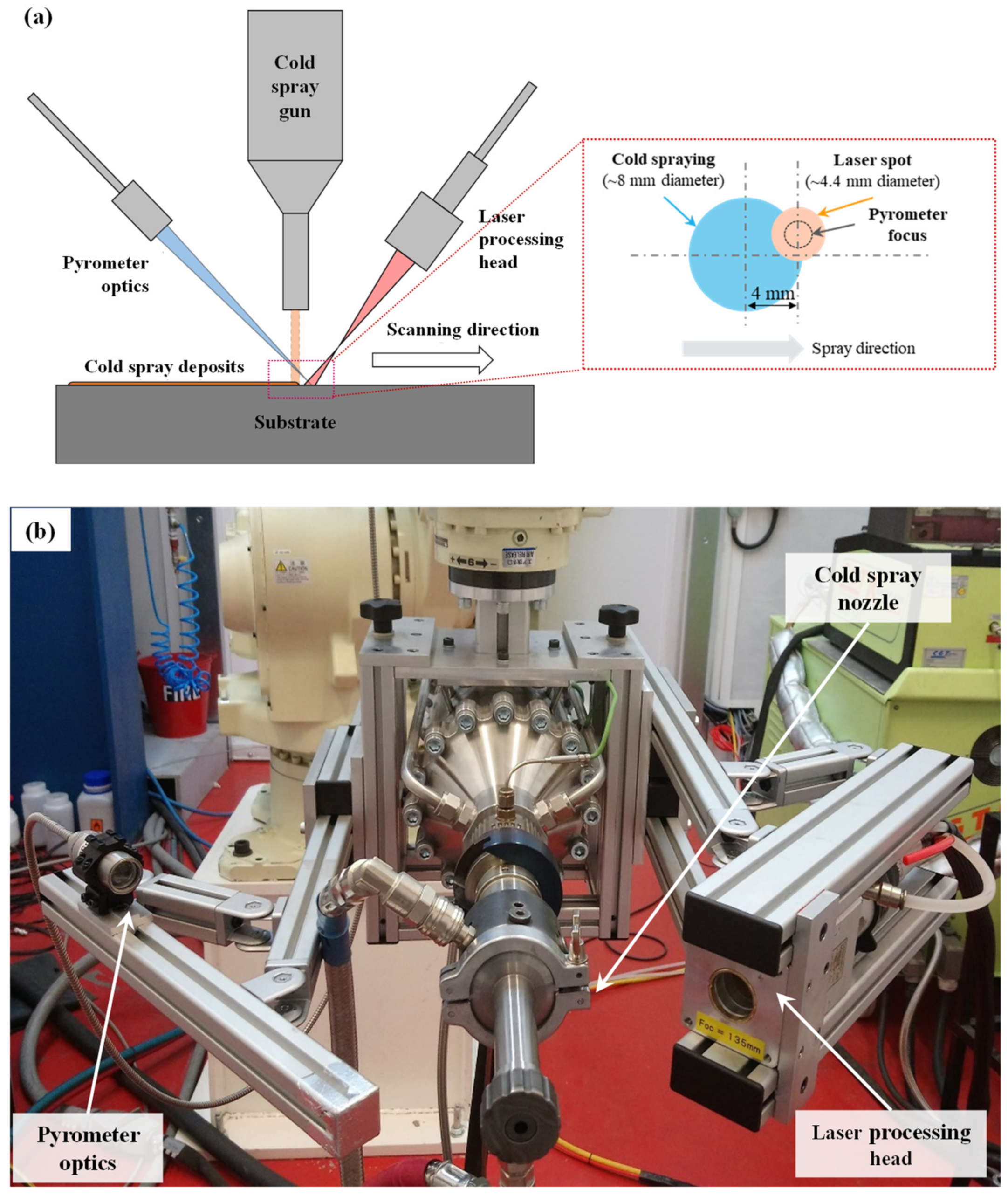
The LCAS system comprises the five main components: (i) laser source, (ii) laser focusing optics, (iii) pyrometer for temperature measurement, (iv) proportional integral derivative (PID) controller, and (v) the CS system. For laser power, a Limo DIOCUT diode laser system (with 1.7 kW of continuous-wave maximum power output at a wavelength of 0.75–1 µm) was used to direct the laser spot ahead of the cold spraying spot. This provided thermal softening in the substrate before depositing a new layer. Laser light was delivered along a 10 m long fibre optic cable (200 µm fibre core) to the laser focusing optics. For temperature measurement, the infrared pyrometer was used which had a SensorTherm MQ22 duel wavelength model with a temperature measurement range of 300–1000 °C. The pyrometer optics was brought into focus on the surface of the samples to be deposited. The laser power was controlled using a PID device (SensorTherm Regulus RF), which measures the surface temperature of the specimen where the deposition was about to occur. This allows the laser power to adjust, keeping the surface temperature of the substrate constant.
The CS system used was Impact Innovation 5/11 High-pressure CS System. During LACS, the laser processing head and the pyrometer are kept in a fixed position relative to the CS nozzle (rigid enough that it maintains alignment during robot movement). Figure 2a shows the schematic of the LACS process, Figure 2b shows the LACS set-up at TWI, a frame attached to the CS gun mounting bracket, which keeps the laser optics and pyrometer aligned to the CS gun while allowing fine adjustment. The laser optics were held on the left-hand side of the CS gun, oriented at an angle of approximately 50° (40° off perpendicular to the substrate). The pyrometer focal point was set to the centre of the laser spot. The laser spot position was aligned 4 mm ahead of the CS nozzle, to ensure that the laser was heating the specimen immediately preceding the CS deposited track. Key process parameters for LACS are shown in Table 1.
Figure 2.
(a) Schematic of the LACS process showing the positions of the laser processing head, pyrometer, and CS nozzle. (b) LACS hardware configuration attached to the Impact 5/11 gun.
Figure 2.
(a) Schematic of the LACS process showing the positions of the laser processing head, pyrometer, and CS nozzle. (b) LACS hardware configuration attached to the Impact 5/11 gun.

Table 1.
Process conditions used to deposit Ti6Al4V LACS coatings.
| CS system setup | Gun | CS system | Impact 5/11 |
| Process gas | N2 | ||
| Nozzle | T24-SiC | ||
| Pre-chamber | Long (128.6 mm) | ||
| Gas pressure (MPa) | 5 | ||
| Gas temperature (°C) | 1100 | ||
| Powder feeder | Dosing disk rotation speed (rpm) | 2 | |
| Powder feed rate (g/min) | 24.67 | ||
| Carrier gas flow rate (m3/hr) | 2 | ||
| Nozzle cooling medium | Water | ||
| Robot and toolpath setup | Gun traverse or scanning speed (mm/s) | 40 | |
| Track spacing (mm) | 1, 2, and 3 (Table 2) | ||
| Spray angle (°) | 90 | ||
| Standoff distance (mm) | 30 | ||
| Toolpath pattern | Horizontal raster | ||
| Laser parameters | Required surface temperature (°C) | 400, 600, and 800 (Table 2) | |
| Stand-off distance (mm) | 195 | ||
| Laser spot diameter (mm) | 4.4 | ||
| Pyrometer distance (mm) | 400 | ||
Table 2.
Specimens details for LACS trials.
| Stages | Sample No. | Laser Substrate Preheating Temperature (°C) | Track Spacing (mm) | Type of Specimen |
|---|---|---|---|---|
| LACS 400 | 400 | - | Single-track deposition | |
| Phase 1 | LACS 600 | 600 | - | |
| LACS 800 | 800 | - | ||
| LACS 600-1 | 600 | 1 | Single-layer (multi-track) deposition with overlapping tracks. | |
| Phase 2 * | LACS 600-2 | 600 | 2 | |
| LACS 600-3 | 600 | 3 |
* An additional standard CS specimen was produced without laser substrate preheating as benchmark to the LACS deposits.
2.3. LACS Deposition Trials
As presented in Table 2, a total of six LACS specimens were produced, i.e., three specimens with single-track deposition in Phase 1, and three specimens with single-layer deposition in Phase 2. To benchmark against the standard or conventional CS process, an additional specimen was produced using the same process parameters as in Table 1 but without laser substrate preheating.
2.3.1. Phase 1: Single-Track LACS Deposition Trials
In Phase 1, single-track (deposits formed by a single deposition track) specimens were produced by depositing onto mill-annealed Ti6Al4V substrates (6 × 30 × 60 mm). Substrates were preheated to 400 °C, 600 °C, and 800 °C, respectively, by laser treatment prior to CS. As mentioned in Section 2.2, to ensure that the laser was heating the specimen immediately preceding the CS deposited track, the laser spot position was aligned 4 mm ahead of the CS nozzle. The laser spot size (~4.4 mm) is much smaller than the CS deposition track size (~8 mm). Therefore, only one-half of the substrate under the CS track gets preheated by the laser. Following the successful completion of the Phase 1 LACS deposition trials and characterisation of single-tracks, a suitable laser substrate preheating temperature was chosen for further investigation in Phase 2.
2.3.2. Phase 2: Single-Layer Multi-Track LACS Deposition Trials
For Phase 2 deposition trials, single-layer (one layer of LACS deposits formed by multiple deposition tracks overlapping with each other) specimens were produced with three different track spacings 1 mm, 2 mm, and 3 mm. Substrates (10 × 30 × 60 mm) were preheated to 600 °C, using laser treatment prior to CS.
2.4. Post-Deposition Thermal Treatment
Solution treatment and ageing (STA) was performed for the Phase 2 LACS (single-layer) specimens in vacuum condition at 940 °C for 1 h with subsequent argon fast cooling. Ageing treatment was carried out at 480 °C for 8 h followed by furnace cooling to room temperature (around 20–25 °C) [7].
2.5. Characterisation of LACS Deposits
Surface profilometry of the LACS single-tracks was carried out to see the variation in surface morphologies at different laser substrate preheating temperatures and to observe the differences between the laser-assisted and non-laser-assisted sides of the tracks. Subsequently, the effect of varying track spacings on the surface roughness of single-layer (multi-track) LACS specimens was investigated. The objective was to determine the track spacing that yields a more evenly distributed coatings. The surface morphology measurements were carried out using the Alicona Infinite Focus SL microscope following ISO 4288 [33].
For metallographic examination, both single-track and single-layer LACS specimens were prepared using a standard metallographic specimen preparation procedure comprising cross-sectioning, mounting, and grinding with SiC abrasive paper discs up to 2500 grit size; followed by polishing with OP-U colloidal silica suspension. The metallographic study of single-track LACS was aimed at understanding the effect of laser substrate preheating temperatures on the adhesion and cohesion characteristics of CS deposits, and also to see the difference in the laser-assisted and non-laser-assisted regions of the tracks. Further, cross-sections of the single-layer LACS specimens were examined to determine the optimal track spacing in terms of microstructure in as-deposited and after STA. Optical microscopy (Olympus BX41M-LED, Tokyo, Japan) and scanning electron microscopy (ZEISS EVO LS 15, Jena, Germany) were used to examine the microstructure of the polished samples. For porosity measurement, a minimum of 20 optical micrographs were taken at 100–200× magnification from unetched specimens. They were analysed according to ASTM E2109 [34] using ImageJ software 1.53 to calculate the cross-sectional area fraction of porosity.
Microhardness measurements were performed on polished cross-sections of coated specimens through the thicknesses of the coating, interface, and up to 5 mm into the sub-strate, using a Zwick Microhardness Tester with Vicker load of 0.1 kg as per ASTM E384 standard [35].
The phase information of LACS deposits compared to feedstock powder, substrate, and CS deposits was examined using a X-ray diffractometer (Bruker’s D8 Advance, Biller-ica, MA, USA), which was performed for a 2θ range of 20° to 90° using a Cu-Kα wave-length λ = 1.5406 Å [7].
2.6. Residual Stress Measurements Using Incremental Center-Hole Drilling
Residual stress measurements were performed using the incremental center-hole drilling (ICHD) technique as per ASTM E837 [36]. Hole drilling is one of the most widely used techniques for residual stress measurements, which involves drilling a small hole in the specimen through the centre of a strain gauge rosette (SGR), and then measuring the relieved surface strains as a result of relaxation of residual stresses in the surrounding material readjusting its stress state to re-attain residual stress equilibrium. Afterwards, the measured strain allows back-calculation of the previously existing residual stresses, assuming the material is isotropic, linear elastic, and the variations of stress within the boundaries of the hole are small.
In this study, residual stresses were measured for the three single-layer specimens as shown in Table 3. Before hole drilling, coating surfaces were smoothened by minor polishing and degreased to allow the attachment of the strain gauge rosette (FRS-2-11). A SGR was glued at the measurement location and connected to lead wires. The drill machine (MTS3000 Restan–SINT Technology, Calenzano, Italy) was aligned to the SGR, and a diamond drill bit with 2 mm diameter was used to drill up to a depth of 1 mm in 20 steps, i.e., strains were measured at each 0.05 mm increment up to 1 mm. The triple strain gauges within the rosette (aligned around the drilled-hole axis with a relative angular spacing of 45°) permitted measurement of the bi-axial residual stress state (i.e., σL, σT, and σLT) where the subscripts L and T stand for the longitudinal and transverse directions, respectively. Residual stresses were subsequently calculated using the Reston evaluation software (EVAL–7.11).
Through-thickness distribution of residual stresses in LACS coatings-substrate systems are predicted using an analytical model for the quenching dominant CS process based on [32,37,38].
where, h is the substrate thickness, ∆h is the average layer thickness, H is the distance from the substrate bottom surface, is the residual stress value in a newly deposited CS layer or near the free surface, n is the number of CS layers , m represents each CS layer below the nth layer (i.e., ), is the total (T) stress increment in the substrate (S) due to deposition of ‘n’ layers (nL), and is the total (T) stress increment in mth layer () due to the deposition of the nth layer (Ln) [32,37,38].
3. Results and Discussion
3.1. Phase 1: Characterisation of Single-Track LACS Deposits
3.1.1. Surface Profilometry
The surface profile of LACS single-track specimens (deposited with three different substrate preheating temperatures viz. 400 °C, 600 °C, and 800 °C, respectively) are presented in Figure 3. The laser spot of 4.4 mm diameter was found to be large enough to heat one-half of the track. It can be observed from Figure 3 that the LACS track profiles were not symmetrical; the laser-assisted side of the tracks was more compact due to higher heat input and possessed lower thickness when compared with the non-laser-assisted side of the tracks. Figure 3 compares the height of the laser-assisted and non-laser-assisted sides of the track (2 mm away from the centre of the track). The height of the laser-assisted side was found to be ~100 µm lower than the non-laser-assisted side.
3.1.2. Microstructure
The SEM microstructures taken from the deposit-substrate cross-sections after single-track LACS deposition, with substrate preheating at 400 °C, 600 °C, and 800 °C are presented in Figure 4. It can be seen in Figure 4b–d that deposits were successfully bonded with intimate contact with the substrates with no sign of delamination. For all three cases, deposited particles were distributed more compactly as compared with CS deposits with no laser substrate preheating. Moreover, intimate contact at the interfaces (both deposit-substrate or adhesion, and particle-particle or cohesion) was observed, especially at 600 °C and 800 °C substrate preheating temperatures. At 400 °C preheating temperature, the deposit-substrate interface appeared to be more or less similar to the standard CS process with a clear distinction of microstructural features between the deposited and substrate material. However, laser substrate preheating to 600 °C and 800 °C increases the deformability of the substrate through thermal softening, resulting in extensive interfacial mixing between the deposited particles and substrate. This is further substantiated by the non-linear nature of the flow stress versus temperature relationship observed in Ti6Al4V. Flow stress of Ti6Al4V is close to its tensile strength at 400 °C and only starts to decline sharply at around 550–600 °C.
The SEM micrographs of the coatings from single-track LACS also show the presence of lamellar α-phase (α plates). The standard CS coating microstructure comprises partially deformed ‘textured’ regions (residue of α’ martensite phase inherited from the feedstock powder) and severely deformed ‘smooth’ regions. However, the LACS deposits showing the presence of finer α plates, and these α plates grew in size as the substrate preheating temperature increased. The LACS 600 and LACS 800 microstructures possess a higher volume fraction of α plates than the LACS 400 sample. This is a result of the higher amount of diffusion happening at a higher temperature that led to the growth of the α-phase. This may also be due to oxygen uptake at higher temperatures stabilisiing the alpha phase. It is important to note that the α-phase also formed at the particle boundaries. The interparticle boundary α-phase grew in size as the temperature increased. In some of the particle boundaries, Widmanstätten α-phase growth is also visible, which grows out of the particle boundary and towards the particle core. The core particle microstructure appears to be a basketweave microstructure.
3.2. Phase 2: Chracterisation of Single-Layer Multi-Track LACS Deposits
3.2.1. Surface Profilometry
The surface profile of the single-layer specimens with three different deposition track spacings (1 mm, 2 mm, and 3 mm) are shown in Figure 5. Among the investigated cases, the specimen deposited with 2 mm track spacing possessed the most evenly distributed deposits with the lowest measured values for all of the three surface roughness parameters (Ra, Rq, Rz), as shown in Figure 5. Moreover, there was some waviness (not shown here), particularly at the edges of the single-layer specimens due to the fluctuation in laser powder, which was found to be more serious for the specimen with 1 mm track spacing. A similar issue with the stability of the laser was also reported in [12].
3.2.2. Microstructure and Porosity
The optical and SEM micrographs of single-layer LACS coatings, deposited using three different track spacing (1 mm, 2 mm, and 3 mm), are shown in Figure 6. Micrographs of the LACS interfaces suggests that a better coating-substrate adhesion was observed at a lower deposition track spacing. It was due to the longer exposure time of the laser beam on the substrate at a lower track spacing. Consequently, higher heat/energy input of the laser beam makes the substrate smoother and softer, and hence promotes extensive deformation resulting in better adhesion with the sprayed particles. This phenomenon was found to be more dominant with the decrease in track spacing from 3 mm to 1 mm. Porosity values were found to be 0.44%, 0.37%, and 0.42%, for track spacing 1 mm, 2 mm, and 3 mm, respectively; which is around 62–68% lower than those achieved using He as a process gas (1.16%) [39] and 81–84% lower than the coating deposited using N2 as a process gas with no laser (i.e., 2.27%) [7]. Figure 7 and Figure 8 show that there was no significant difference in cross-sectional area porosities among LACS coatings deposited with varying track spacing. Deposited particles were closely bonded to neighbour particles with no interconnected porosity, unlike standard CS Ti6Al4V coatings. The lowest measured porosity was 0.37% with 2 mm track spacing, with surface profilometry measurements also showing a more evenly distributed coating when deposited with 2 mm track spacing. Birt et al. [15] have also achieved less than 1% porosity for LACS Ti6Al4V, however, process parameters were significantly different from this study. They have used N2 as the process gas at 550 °C and 3–4 MPa, with laser preheating surface temperature was recorded upto 900 °C [15].
The SEM micrograph of the LACS coating with 1 mm track spacing suggests that lamellar α-phase (α plates) and interparticle boundary α-phase are present in the microstructure, as explained in Section 3.1.2. The amounts of α plates seen in the coatings deposited with 2 mm and 3 mm spacings were found to be relatively lesser than the coatings deposited with 1 mm track spacing. This is associated with the repeated re-heating and the heat intensity of the deposited layer, with 1 mm track spacing. The microstructure obtained from LACS deposition using 2 mm and 3 mm track spacings are similar to what has been observed for standard CS coating, albeit with better cohesion and adhesion.
3.2.3. Phase Analysis Using X-ray Diffraction
The XRD patterns obtained from feedstock powder, mill-annealed substrate, the standard CS coating, and LACS coatings with different track spacings are shown in Figure 9. It is obvious from the peaks that the α-phase is present in the microstructure for all of the coated samples, as also observed in the SEM micrographs. No significant difference in the peak positions was observed for the α’ (observed in powder) and α-phase, indicating their similar microstructure.
3.2.4. Microhardness
The microhardness of LACS deposits in comparison with standard CS deposits, feedstock powder, and mill-annealed Ti6Al4V substrate is shown in Figure 10. Through-thickness hardness distribution is shown in Figure 11. Average hardness values in LACS deposits (388–403 HV) were found to be comparable to mill-annealed Ti6Al4V substrate (393 HV), but lower than the standard CS deposits (429 HV). However, at a deposition track spacing of 1 mm, hardness was relatively higher and values were less consistent when compared with 2 mm and 3 mm track spacing deposits. Higher scatter for the 1 mm track spacing deposits was mainly due to very high hardness values, measured just above the coating side of the interface reaching >550 HV (average 455 ± 78 HV), which is an indication of the heat affected zone (HAZ) due to the formation of titanium oxide as a result of laser treatment. Li et al. [13] have reported the presence of two HAZs in LACS Ti deposits, one with lamellae microstructure with coarse grains and another with equiaxed microstructure with smaller grains caused by laser heat-promoted recrystallisation. Birt et al. [15] have also reported similar hardness values for LACS Ti6Al4V coatings, however exceptionally high hardness (>900 HV) was also reported on samples sprayed at higher laser powers due the formation of secondary phases. However, for a better understanding, further microstructural investigation is required for LACS Ti6Al4V deposit-substrate interfaces. The microhardness of the coating deposited with 1 mm track spacing was found to be higher (particularly close to the substrate) due to the higher amount of α-phase observed in the microstructure (Figure 6). The hardness decreased slightly as the track spacing was increased since the amount of α-phase decreased with an increase in the track spacing.
3.3. Residual Stresses in Single-Layer LACS Deposits
Residual stresses in the LACS coatings (single-layer with three different track spacings: 1 mm, 2 mm, or 3 mm) measured using the ICHD are shown in Figure 12. Figure 12a shows residual stress distribution in the coating, and the lines denote the best-fitted polynomial trendline; the solid lines representing longitudinal component and the dotted lines representing transverse stress component. Figure 12b shows a comparison of the residual stresses in three different coatings for both transverse and longitudinal directions. Although measurements were performed up to a depth of 1 mm in the coating-substrate assembly, stresses were presented only up to 0.5 mm as there was a higher scatter in the strain measurements at higher depths. Residual stresses were found to be tensile for all three coatings and can be categorised as quenching dominant [32], which was due to higher process gas temperature/pressure (1100 °C, 5 MPa) along with high heat input during laser preheating of the substrate to 600 °C. However, an interesting trend in residual stresses was observed (i.e., the higher the deposition track spacing, the higher the magnitude of tensile residual stresses in the coating layer). The lower residual stresses at a lower track spacing (i.e., 1 mm) might be due to partial relieving of the induced quenching stresses by the annealing effect, resulting from longer exposer to the combined effect of laser preheating and higher process gas temperature. Since the heat-induced through laser preheating was higher at a lower track spacing (due to long exposure to laser preheating), the opposing annealing effect on the induced quenching stresses was higher for specimens deposited at a lower track spacing. This results in lower tensile residual stresses in the coatings with a lower track spacing. The hypothesis of the opposing annealing effect of high gas temperature on the induced stresses was also reported in [40]. It was reported that there is a linear relation between annealing time and relieved stresses for coatings deposited at the same temperature. Hence, the shorter the spraying time and/or the lower the spraying temperature, the less the annealing effect, hence less stress being relieved [39].
For the analytical prediction of residual stresses in single-layer specimens with 3 mm, 2 mm, and 1 mm track spacings, the ‘k’ value in Equations (1) and (2) were set as 191 MPa, 135 MPa, and 31 MPa, respectively, based on the measured residual stresses in the coating using incremental center-hole drilling (longitudinal component). Other parameters used for calculations are based on Table 3. Figure 13 shows a comparison among through-thickness distributions of residual stresses in LACS specimens.
Based on the analysis of residual stress, the 1 mm track spacing is optimal for producing multi-track LACS deposits with minimal residual stress, making it potentially suitable for multi-layer deposition. However, the 2 mm track spacing exhibited slightly superior performance in other aspects stated earlier, including more evenly distributed deposits, the lowest measured porosity, good interfacial mixing, and consistent through-thickness hardness comparable to mill annealed Ti6Al4V. Therefore, considering all these factors, including residual stress and other characteristics mentioned in Section 3.2, a deposition track spacing in between 1 mm and 2 mm (for instance, 1.5 mm) appears to be optimal for depositing multiple LACS layers.
3.4. Effect of Heat Treatment on the Microstructure of LACS Deposits
The SEM micrographs obtained after solution treatment and ageing treatment are shown in Figure 14. Solution treatment was performed at 940 °C for 1 h with subsequent argon fast cooling, and ageing at 480 °C for 8 h followed by furnace cooling. The microstructure for the coating deposited using the standard CS process shows the presence of fully equiaxed microstructure. This has formed due to the fact that the CS process deforms the microstructure and when the solution treatment is carried out, recrystallisation of the microstructure happens. As the heat treatment is carried out below the β-transus temperature of Ti6Al4V alloy (~980 °C) [41], only the α-phase grows. The heat-treated LACS coating with 1 mm track spacing showed the presence of lamellar α-phase (grey colour) in the β-phase (bright colour). This kind of microstructure was the result of α-phase growth observed before heat treatment (Figure 6). The heat-treated LACS coating with 2 mm track spacing showed the presence of lamellar α-phase in the β-phase. The heat-treated LACS coating with 3 mm track spacing showed the presence of a bimodal microstructure, namely a lamellar α-phase and equiaxed microstructure.
4. Conclusions
To characterise laser assisted cold spray (LACS) deposited Ti6Al4V alloy, two types of specimens were produced: (i) single-track deposited on Ti6Al4V substrates preheated to 400 °C, 600 °C, and 800 °C, respectively, and (ii) single-layer (multi-track) deposited on Ti6Al4V substrates preheated to 600 °C with track spacing 1 mm, 2 mm, and 3 mm, respectively. The single-track specimens were studied in terms of surface profilometry and cross-sectional microstructure. The single-layer specimens were investigated in terms of surface profilometry, microstructure, microhardness, and residual stress. Notable contributions of this study include enhanced coating-substrate adhesion through extensive interfacial mixing, a significant reduction in cross-sectional area porosity as compared to standard cold spray (CS), and insights into the effects of residual stresses. Collectively, these findings contribute to a deeper understanding of LACS technology and its potential advantages over conventional CS technique, offering new possibilities for improving the quality and performance of Ti6Al4V deposits. Key findings from this study can be summarised as follows:
- For single-track specimens, the surface profiles exhibited asymmetry. The laser-assisted side of the tracks were more compact and possessed lower thicknesses compared to the non-laser-assisted side. For single-layer specimens, LACS deposits with 2 mm track spacing showed the most even distribution.
- Cross-sectional microstructure of the single-track deposits revealed intimate contact at the interfaces, showcasing extensive interfacial mixing, particularly for specimens laser preheated to substrate temperatures of 600 °C and 800 °C. For single-layer specimens, superior coating-substrate adhesion was observed at the narrowest deposition track spacing (1 mm).
- Cross-sectional area fraction of porosity values were found to be in the range of 0.37% to 0.44%, for LCAS deposits with track spacings 1 mm, 2 mm, and 3 mm; which is 81–84% lower than the porosity content in standard CS without laser preheating (2.27%).
- Average microhardness values were found to be 403 HV, 397 HV, and 388 HV, for LCAS deposits with track spacing 1 mm, 2 mm, and 3 mm, respectively. They are comparable to mill-annealed Ti6Al4V substrate (393 HV) but lower than the standard CS deposits without laser preheating (429 HV). For LACS deposits with 1 mm track spacing, hardness values were particularly high near the interface exceeding 550 HV, attributed to the formation of a localised heat-affected zone.
- Tensile bi-axial residual stresses were observed in all three LACS coatings, attributed to the elevated process gas temperature (1100 °C) and substantial heat input from laser preheating of the substrate to 600 °C. The longitudinal tensile residual stresses in the LACS coatings deposited with 1 mm, 2 mm, and 3 mm track spacings were measured as 31 MPa, 135 MPa, and 191 MPa, respectively.
- Heat treatments led to distinct microstructures in LACS coatings, including fully equiaxed or lamellar α-phase within the β-phase or a bimodal microstructure influenced by track spacing variations.
Author Contributions
Conceptualization, D.B. and P.M.; methodology, D.B. and P.M.; formal analysis, D.B.; investigation, D.B.; resources, X.Z., H.B. and P.M.; data curation, D.B.; writing—original draft preparation, D.B.; writing—review and editing, D.B., D.S., H.B. and X.Z.; visualization, D.B. and P.M.; supervision, X.Z.; funding acquisition, X.Z. All authors have read and agreed to the published version of the manuscript.
Funding
This work was supported by the Lloyd’s Register Foundation under Grant number DB012017COV; and Coventry University under grant number 7486157.
Data Availability Statement
The data presented in this study are available within the article. There is no additional data available.
Acknowledgments
This research was enabled through and undertaken at the National Structural Integrity Research Centre, a postgraduate engineering facility for industry-led research into structural integrity established and managed by TWI Ltd. This work was sponsored by the Lloyd’s Register Foundation, a charitable organisation that helps to protect life and property by supporting engineering-related education, public engagement and the application of research. The authors would like to thank Jazeel Chukkan from TWI Ltd. for supporting residual stress measurements, Matthew Dore from TWI Ltd., Abdul Khadar Syed from Coventry University, and Shiladitya Paul from University of Leicester for their support in various phases of this project.
Conflicts of Interest
The authors declare no conflict of interest. The funders had no role in the design of the study; in the collection, analyses, or interpretation of data; in the writing of the manuscript; or in the decision to publish the results.
References
- Assadi, H.; Kreye, H.; Gärtner, F.; Klassen, T. Cold spraying—A materials perspective. Acta Mater. 2016, 116, 382–407. [Google Scholar] [CrossRef]
- Grigoriev, S.; Okunkova, A.; Sova, A.; Bertrand, P.; Smurov, I. Cold spraying: From process fundamentals towards advanced applications. Surf. Coat. Technol. 2015, 268, 77–84. [Google Scholar] [CrossRef]
- Villafuerte, J. Modern Cold Spray: Materials, Process, and Applications. In Modern Cold Spray: Materials, Process, and Applications; Springer: Berlin/Heidelberg, Germany, 2015; pp. 1–429. [Google Scholar]
- Sova, A.; Grigoriev, S.; Okunkova, A.; Smurov, I. Potential of cold gas dynamic spray as additive manufacturing technology. Int. J. Adv. Manuf. Technol. 2013, 69, 2269–2278. [Google Scholar] [CrossRef]
- Yin, S.; Cavaliere, P.; Aldwell, B.; Jenkins, R.; Liao, H.; Li, W.; Lupoi, R. Cold spray additive manufacturing and repair: Fundamentals and applications. Addit. Manuf. 2018, 21, 628–650. [Google Scholar] [CrossRef]
- Boyer, R.R. Titanium for aerospace: Rationale and applications. Adv. Perform. Mater. 1995, 2, 349–368. [Google Scholar] [CrossRef]
- Boruah, D.; Zhang, X.; McNutt, P.; Khan, R.; Begg, H. Effect of Post-Deposition Thermal Treatments on Tensile Properties of Cold Sprayed Ti6Al4V. Metals 2022, 12, 1908. [Google Scholar] [CrossRef]
- Boruah, D.; Zhang, X. Effect of Post-Deposition Solution Treatment and Ageing on Improving Interfacial Adhesion Strength of Cold Sprayed Ti6Al4V Coatings. Metals 2021, 11, 2038. [Google Scholar] [CrossRef]
- Allen, R.; Marrocco, C.M.; McNutt, T.; Koivuluoto, P.; Latokartano, H.; Vuoristo, J.; Olsson, P. A novel coaxially laser-assisted (COLA) cold spray system. In Proceedings of the International Thermal Spray Conference, ASM International, Long Beach, CA, USA, 11 May 2015; Agarwal, E.T.A., Lau, Y.-C., McDonald, A., Bolelli, G., Toma, F.-L., Concustell, A., Widener, C.A., Eds.; ASM International: Materials Park, OH, USA, 2015; pp. 210–216. [Google Scholar]
- Bray, M.; Cockburn, A.; O’Neill, W. The Laser-assisted Cold Spray process and deposit characterization. Surf. Coat. Technol. 2009, 203, 2851–2857. [Google Scholar] [CrossRef]
- Olakanmi, E.O.; Doyoyo, M. Laser-assisted cold-sprayed corrosion- and wear-resistant coatings: A review. J. Therm. Spray Technol. 2014, 23, 765–785. [Google Scholar] [CrossRef]
- Walker, M.; Howes, P.; McNutt, P.; Harvey, D. Residual stress development of laser assisted cold sprayed Ni alloy 718 coatings. In Proceedings of the ITSC 2019—Proceedings of the International Thermal Spray Conference, Yokohama, Japan, 26–29 May 2019; Azarmi, K.S.F., Lau, Y., Veilleux, J., Widener, C., Toma, F., Koivuluoto, H., Balani, K., Li, H., Eds.; ASM International: Materials Park, OH, USA, 2019. [Google Scholar]
- Li, W.; Cao, C.; Yin, S. Solid-state cold spraying of Ti and its alloys: A literature review. Prog. Mater. Sci. 2020, 110, 100633. [Google Scholar] [CrossRef]
- Perton, M.; Costil, S.; Wong, W.; Poirier, D.; Irissou, E.; Legoux, J.G.; Blouin, A.; Yue, S. Effect of pulsed laser ablation and continuous laser heating on the adhesion and cohesion of cold sprayed Ti-6Al-4V coatings. J. Therm. Spray Technol. 2012, 21, 1322–1333. [Google Scholar] [CrossRef]
- Birt, A.M.; Champagne, V.K., Jr.; Sisson, R.D., Jr.; Apelian, D. Statistically Guided Development of Laser-Assisted Cold Spray for Microstructural Control of Ti-6Al-4V. Metall. Mater. Trans. A 2017, 48, 1931–1943. [Google Scholar] [CrossRef]
- Olakanmi, E.O. Optimization of the Quality Characteristics of Laser-Assisted Cold-Sprayed (LACS) Aluminum Coatings with Taguchi Design of Experiments (DOE). Mater. Manuf. Process. 2016, 31, 1490–1499. [Google Scholar] [CrossRef]
- Christoulis, D.K.; Jeandin, M.; Irissou, E.; Legoux, J.; Knapp, W. Laser-Assisted Cold Spray (LACS). In Nd YAG Laser; Dumitras, D.C., Ed.; InTech: Rijeka, Croatia, 2012; pp. 59–96. [Google Scholar]
- Koivuluoto, H.; Milanti, A.; Bolelli, G.; Latokartano, J.; Marra, F.; Pulci, G.; Vihinen, J.; Lusvarghi, L.; Vuoristo, P. Structures and Properties of Laser-Assisted Cold-Sprayed Aluminum Coatings. Mater. Sci. Forum 2017, 879, 984–989. [Google Scholar] [CrossRef]
- Masaylo, D.; Orlov, A.; Igoshin, S. Investigation of Aluminum Composite Produced by Laser-Assisted Cold Spray Additive Manufacturing. Key Eng. Mater. 2019, 822, 534–541. [Google Scholar] [CrossRef]
- Zhang, C.; Zhang, D.; Luo, C.; Peng, W.; Zang, X. Nanosecond-pulse laser assisted cold spraying of Al-Cu aluminum alloy. Coatings 2021, 11, 267. [Google Scholar] [CrossRef]
- Olakanmi, E.O.; Tlotleng, M.; Meacock, C.; Pityana, S.; Doyoyo, M. Deposition mechanism and microstructure of laser-assisted cold-sprayed (LACS) Al-12 wt.%Si coatings: Effects of laser power. JOM 2013, 65, 776–783. [Google Scholar] [CrossRef]
- Dey, D.; Sarkar, S.; Mahata, A.; Roy Choudhury, A.; Nath, A.K. Laser assisted cold spray of 15–5 PH stainless steel in a designed and developed setup. Opt. Laser Technol. 2023, 158, 108902. [Google Scholar] [CrossRef]
- Barton, D.J.; Bhattiprolu, V.S.; Thompson, G.B.; Brewer, L.N. Laser assisted cold spray of AISI 4340 steel. Surf. Coat. Technol. 2020, 400, 126218. [Google Scholar] [CrossRef]
- Nikbakht, R.; Cojocaru, C.V.; Aghasibeig, M.; Irissou, É.; Kim, T.S.; Kim, H.S.; Jodoin, B. Cold Spray and Laser-Assisted Cold Spray of CrMnCoFeNi High Entropy Alloy Using Nitrogen as the Propelling Gas. J. Therm. Spray Technol. 2022, 31, 1129–1142. [Google Scholar] [CrossRef]
- Cojocaru, C.V.; Aghasibeig, M.; Irissou, E. NiCoCrAlX (X = Y, Hf and Si) Bond Coats by Cold Spray for High Temperature Applications. J. Therm. Spray Technol. 2022, 31, 176–185. [Google Scholar] [CrossRef] [PubMed]
- Barton, D.J.; Bhattiprolu, V.S.; Hornbuckle, B.C.; Batali, C.M.; Darling, K.A.; Thompson, G.B.; Brewer, L.N. Residual Stress Generation in Laser-Assisted Cold Spray Deposition of Oxide Dispersion Strengthened Fe91Ni8Zr1. J. Therm. Spray Technol. 2020, 29, 1550–1563. [Google Scholar] [CrossRef]
- Barton, D.J.; Hornbuckle, B.C.; Darling, K.A.; Brewer, L.N.; Thompson, G.B. Influence of surface temperature in the laser assisted cold spray deposition of sequential oxide dispersion strengthened layers: Microstructure and hardness. Mater. Sci. Eng. A 2021, 811, 141027. [Google Scholar] [CrossRef]
- Story, W.A.; Barton, D.J.; Hornbuckle, B.C.; Darling, K.A.; Thompson, G.B.; Brewer, L.N. Laser assisted cold spray of Fe-Ni-Zr oxide dispersion strengthened steel. Materialia 2018, 3, 239–242. [Google Scholar] [CrossRef]
- Tlotleng, M.; Akinlabi, E.; Shukla, M.; Pityana, S. Microstructural and Mechanical Evaluation of Laser-Assisted Cold Sprayed Bio-ceramic Coatings: Potential Use for Biomedical Applications. J. Therm. Spray Technol. 2015, 24, 423–435. [Google Scholar] [CrossRef]
- ASTM B822-17; Standard Test Method for Particle Size Distribution of Refractory Metal Powders and Related Compounds by Light Scattering. ASTM International: West Conshohocken, PA, USA, 2017.
- Boruah, D.; Robinson, B.; London, T.; Wu, H.; de Villiers-Lovelock, H.; McNutt, P.; Doré, M.; Zhang, X. Experimental evaluation of interfacial adhesion strength of cold sprayed Ti-6Al-4V thick coatings using an adhesive-free test method. Surf. Coat. Technol. 2020, 381, 125130. [Google Scholar] [CrossRef]
- Boruah, D.; Ahmad, B.; Lee, T.L.; Kabra, S.; Syed, A.K.; McNutt, P.; Doré, M.; Zhang, X. Evaluation of residual stresses induced by cold spraying of Ti-6Al-4V on Ti-6Al-4V substrates. Surf. Coat. Technol. 2019, 374, 591–602. [Google Scholar] [CrossRef]
- ISO 4288:1996; Geometrical Product Specifications (GPS)—Surface Texture: Profile Method—Rules and Procedures for the Assessment of Surface Texture. ISO: Geneva, Switzerland, 1996.
- ASTM E2109-01; Standard Test Methods for Determining Area Percentage Porosity in Thermal Sprayed Coatings. ASTM International: West Conshohocken, PA, USA, 2014.
- ASTM E384-17; Standard Test Method for Microindentation Hardness of Materials. ASTM International: West Conshohocken, PA, USA, 2017.
- ASTM E837-13a; Standard Test Method for Determining Residual Stresses by the Hole-Drilling Strain-Gage Method. ASTM International: West Conshohocken, PA, USA, 2013.
- Boruah, D.; Zhang, X.; Doré, M. Theoretical prediction of residual stresses induced by cold spray with experimental validation. Multidiscip. Model. Mater. Struct. 2019, 15, 599–616. [Google Scholar] [CrossRef]
- Boruah, D.; Zhang, X.; Doré, M. An analytical method for predicting residual stress distribution in selective laser melted/sintered alloys. In Proceedings of the 10th European Conference on Residual Stresses 2018—ECRS-10, Leuven, Belgium, 11–14 September 2018; Materials Research Proceedings. Volume 6, pp. 283–288. [Google Scholar]
- Chen, C.; Xie, Y.; Yan, X.; Yin, S.; Huang, R.; Zhao, R.; Wang, J.; Ren, Z.; Liu, M.; Liao, H. Effect of hot isostatic pressing (HIP) on microstructure and mechanical properties of Ti6Al4V alloy fabricated by cold spray additive manufacturing. Addit. Manuf. 2019, 27, 595–605. [Google Scholar] [CrossRef]
- Ghelichi, R.; Bagherifard, S.; Macdonald, D.; Fernandez-Pariente, I.; Jodoin, B.; Guagliano, M. Experimental and numerical study of residual stress evolution in cold spray coating. Appl. Surf. Sci. 2014, 288, 26–33. [Google Scholar] [CrossRef]
- Sharma, D.; Kamran, M.; Paraye, N.K.; Anant, R. Insights into the wear behaviour of electron beam melted Ti–6Al–4V alloy in the as-built and the heat-treated conditions. J. Manuf. Process. 2021, 71, 669–678. [Google Scholar] [CrossRef]
Figure 1.
Characteristics of the gas atomised Ti6Al4V powder: (a) size distribution showing d10 17 μm, d50 23 μm, d90 32 μm, (b) powder morphology, (c) microstructure of as-received powder showing the rapidly solidified α’ martensitic needles. (Adopted with permission from [31]. 2023, Elsevier).
Figure 1.
Characteristics of the gas atomised Ti6Al4V powder: (a) size distribution showing d10 17 μm, d50 23 μm, d90 32 μm, (b) powder morphology, (c) microstructure of as-received powder showing the rapidly solidified α’ martensitic needles. (Adopted with permission from [31]. 2023, Elsevier).

Figure 3.
Single-track LACS Ti6Al4V profiles for three substrate preheating temperatures (400 °C, 600 °C, and 800 °C): (a) surface profile maps (laser-heated side on left), (b) surface profile across the width of single-tracks, (c) track height from the 2 mm from its centre (A: laser preheated substrate side, B: substrates with no laser pre-heating).
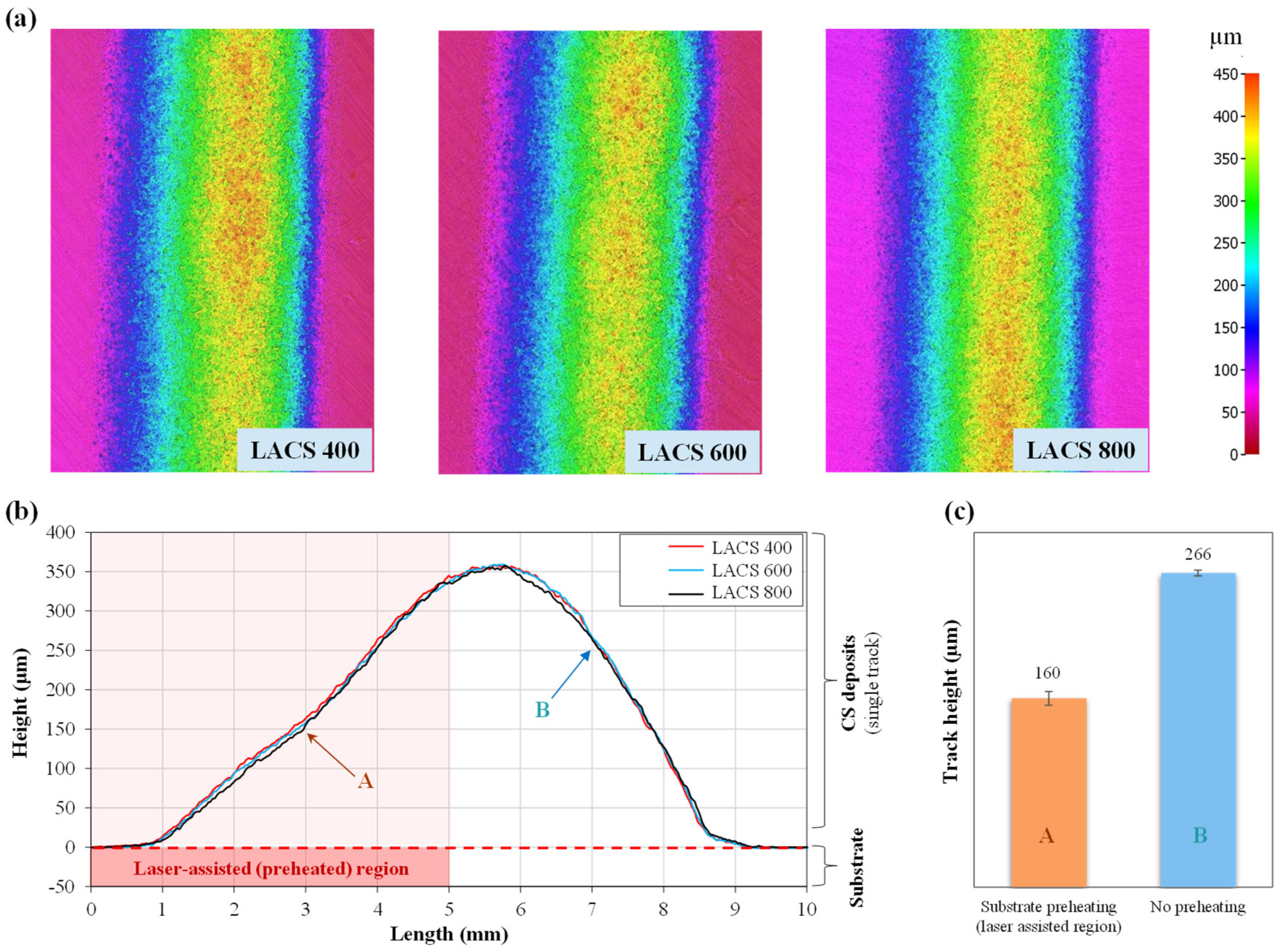
Figure 4.
Cross-sectional SEM BSE microstructure of interfaces (Ti6Al4V deposited onto Ti6Al4V substrates) showing: (a) standard cold spray deposits with no laser substrate preheating, single-track LACS deposits with laser substrate preheating to (b) 400 °C, (c) 600 °C, and (d) 800 °C.
Figure 4.
Cross-sectional SEM BSE microstructure of interfaces (Ti6Al4V deposited onto Ti6Al4V substrates) showing: (a) standard cold spray deposits with no laser substrate preheating, single-track LACS deposits with laser substrate preheating to (b) 400 °C, (c) 600 °C, and (d) 800 °C.

Figure 5.
Surface roughness profile maps of single-layer LACS Ti6Al4V specimens deposited with a track spacing of (a) 1 mm, (b) 2 mm, and (c) 3 mm; (d) comparison of surface roughness (Ra, Rq, Rz) values among coatings deposited by three different track spacings.
Figure 5.
Surface roughness profile maps of single-layer LACS Ti6Al4V specimens deposited with a track spacing of (a) 1 mm, (b) 2 mm, and (c) 3 mm; (d) comparison of surface roughness (Ra, Rq, Rz) values among coatings deposited by three different track spacings.
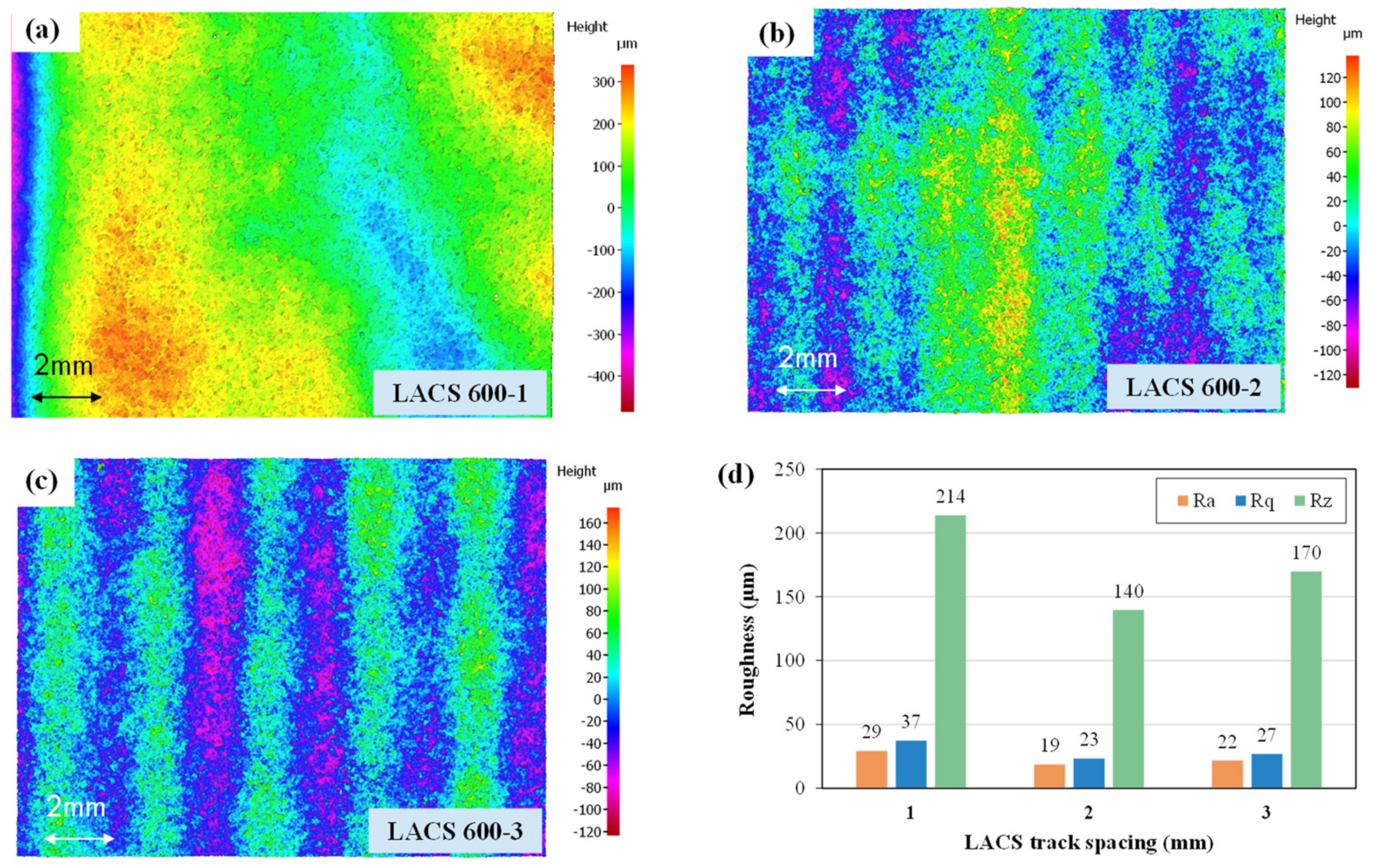
Figure 6.
Cross-sectional optical micrographs (etched) and SEM BSE images of single-layer LACS specimens with substrate preheated to 600 °C, showing interfaces between coating and substrate using three different track spacings, (a,b): 1 mm, (c,d): 2 mm, and (e,f): 3 mm. (of which (a,c,e) are optical micrographs, and (b,d,f) are SEM images).
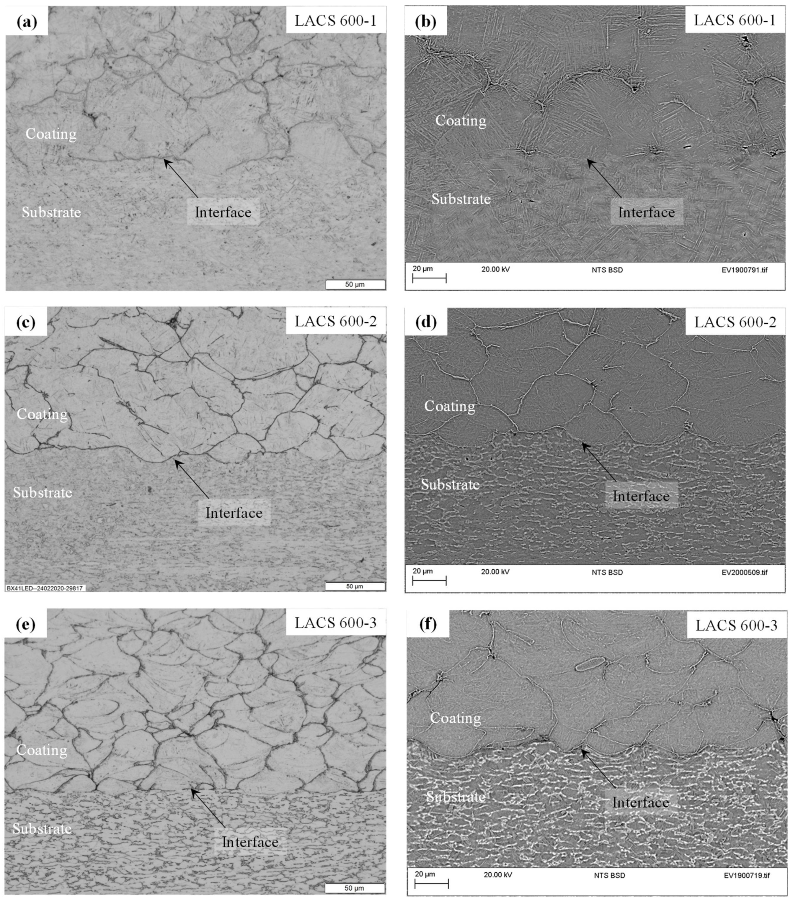
Figure 7.
Optical micrographs of Ti6Al4V deposits (single-layer) comparing mesostructure showing presence of pores/defects in (a) standard CS, and LACS deposits with laser substrate preheating to 600 °C with track spacing (b) 1 mm, (c) 2 mm, and (d) 3 mm.
Figure 7.
Optical micrographs of Ti6Al4V deposits (single-layer) comparing mesostructure showing presence of pores/defects in (a) standard CS, and LACS deposits with laser substrate preheating to 600 °C with track spacing (b) 1 mm, (c) 2 mm, and (d) 3 mm.
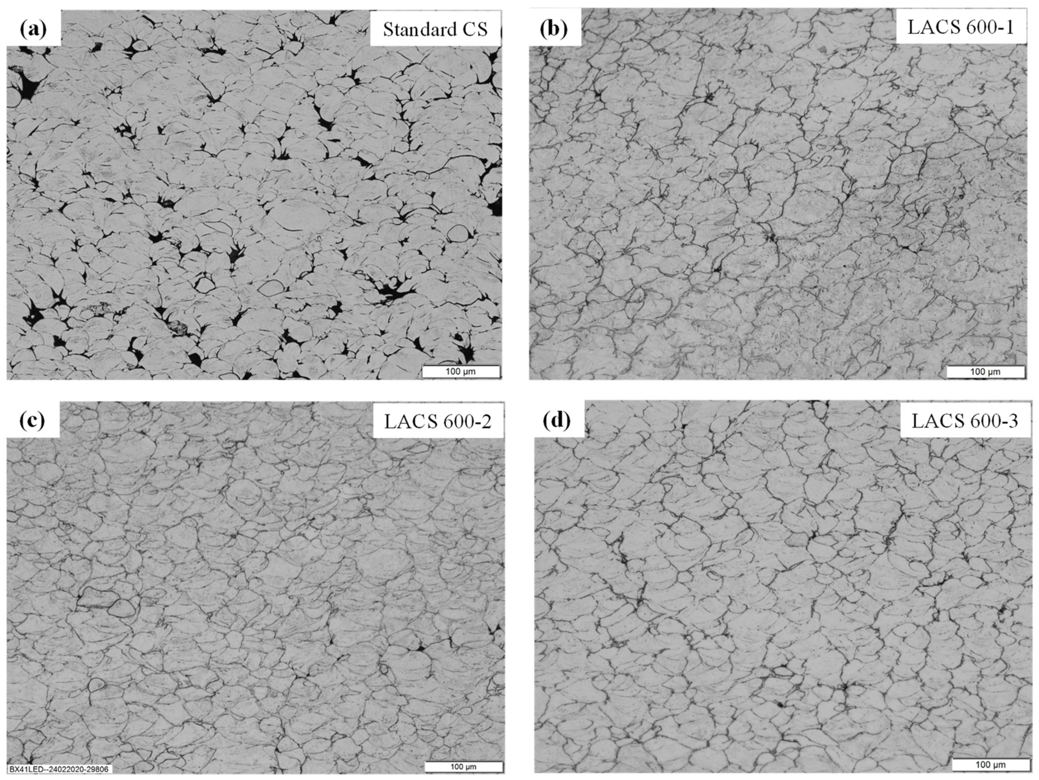
Figure 8.
Cross-sectional area porosity in LACS Ti6Al4V deposits (for three different track spacings) as compared to standard CS Ti6Al4V deposits.
Figure 8.
Cross-sectional area porosity in LACS Ti6Al4V deposits (for three different track spacings) as compared to standard CS Ti6Al4V deposits.
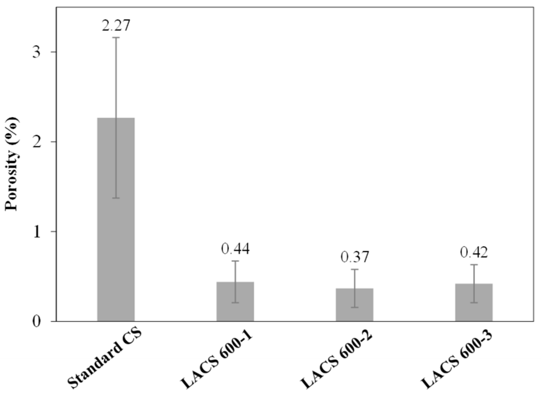
Figure 9.
XRD patterns obtained from feedstock powder, mill-annealed substrate, the standard CS coating, and LACS coatings with different track spacings.
Figure 9.
XRD patterns obtained from feedstock powder, mill-annealed substrate, the standard CS coating, and LACS coatings with different track spacings.
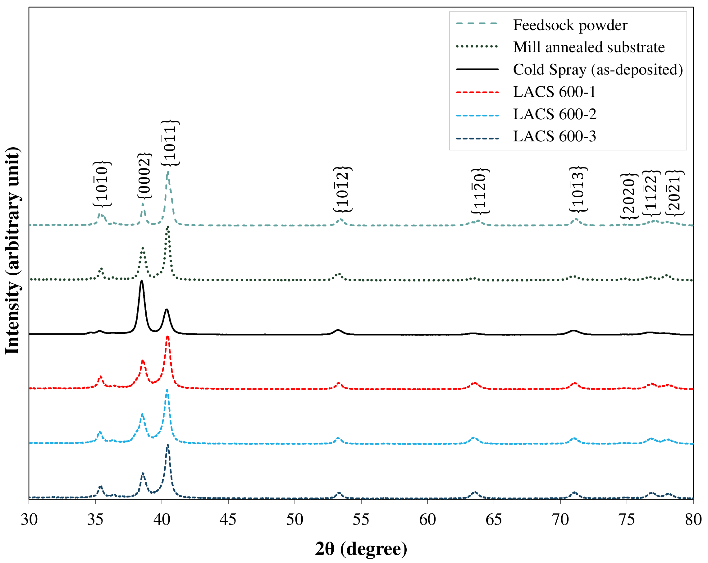
Figure 10.
Hardness of LACS deposits in comparison to standard CS, and mill-annealed Ti6Al4V. LACS specimens were deposited at 600 °C substrate preheating with three different track spacings: 1 mm, 2 mm, and 3 mm (i.e., LACS 600-1, LACS 600-2, LACS 600-3).
Figure 10.
Hardness of LACS deposits in comparison to standard CS, and mill-annealed Ti6Al4V. LACS specimens were deposited at 600 °C substrate preheating with three different track spacings: 1 mm, 2 mm, and 3 mm (i.e., LACS 600-1, LACS 600-2, LACS 600-3).
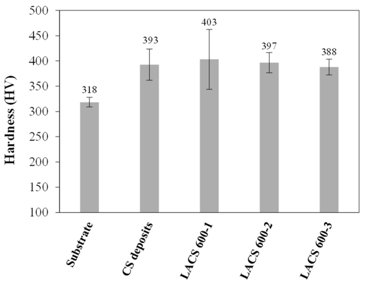
Figure 11.
Through-thickness hardness distributions in single-layer LACS Ti6Al4V deposit-substrate interfaces, deposited at 600 °C laser substrate preheating with three different track spacings: 1 mm, 2 mm, and 3 mm (i.e., LACS 600-1, LACS 600-2, LACS 600-3).
Figure 11.
Through-thickness hardness distributions in single-layer LACS Ti6Al4V deposit-substrate interfaces, deposited at 600 °C laser substrate preheating with three different track spacings: 1 mm, 2 mm, and 3 mm (i.e., LACS 600-1, LACS 600-2, LACS 600-3).
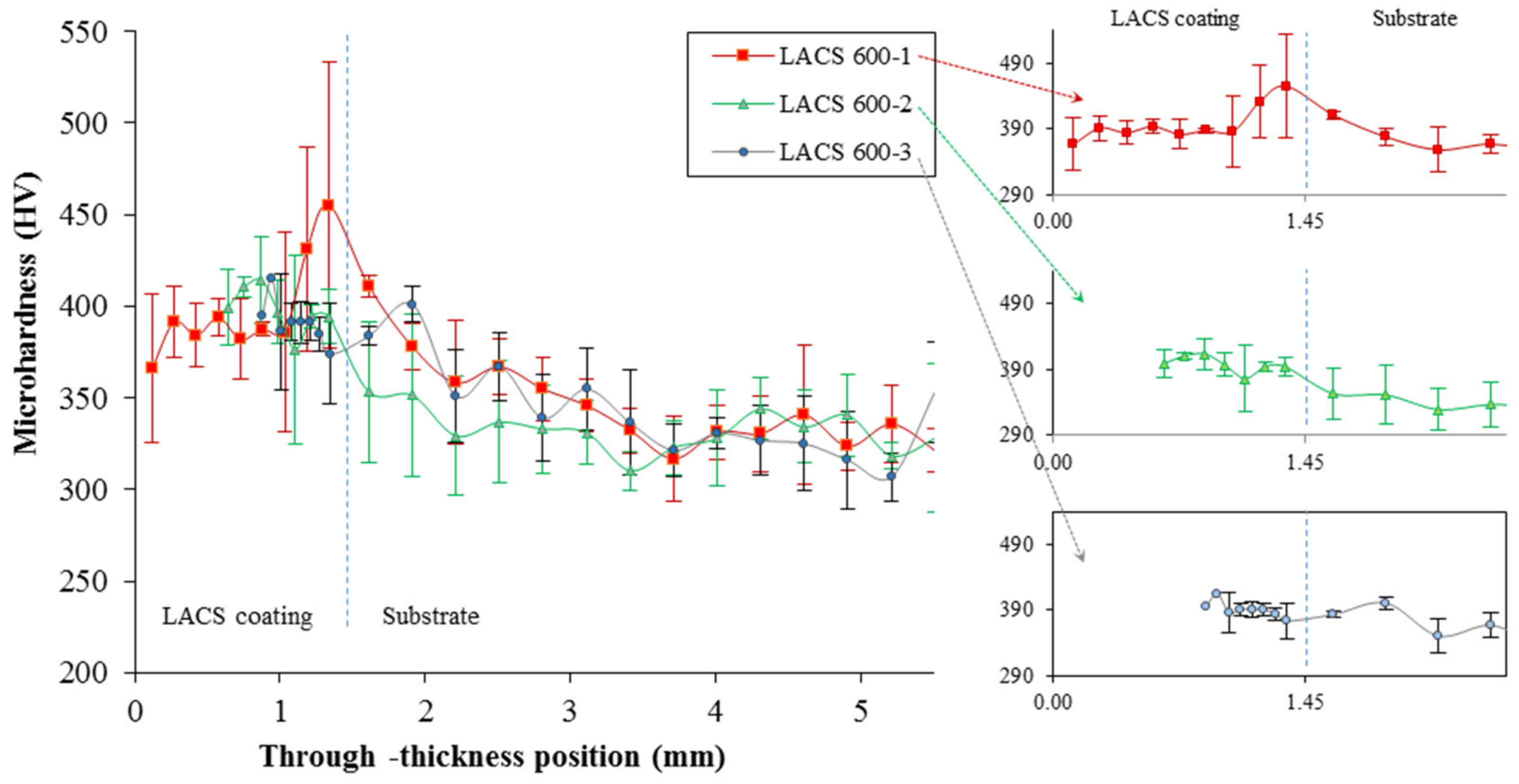
Figure 12.
LACS Ti6Al4V coatings: (a) residual stress distribution from the top of the coatings up to 0.5 mm depth, lines denoting the best-fitted polynomial trendline (solid lines: longitudinal component, and dotted lines: transverse component). (b) average residual stresses in the coatings in the transverse and longitudinal direction.
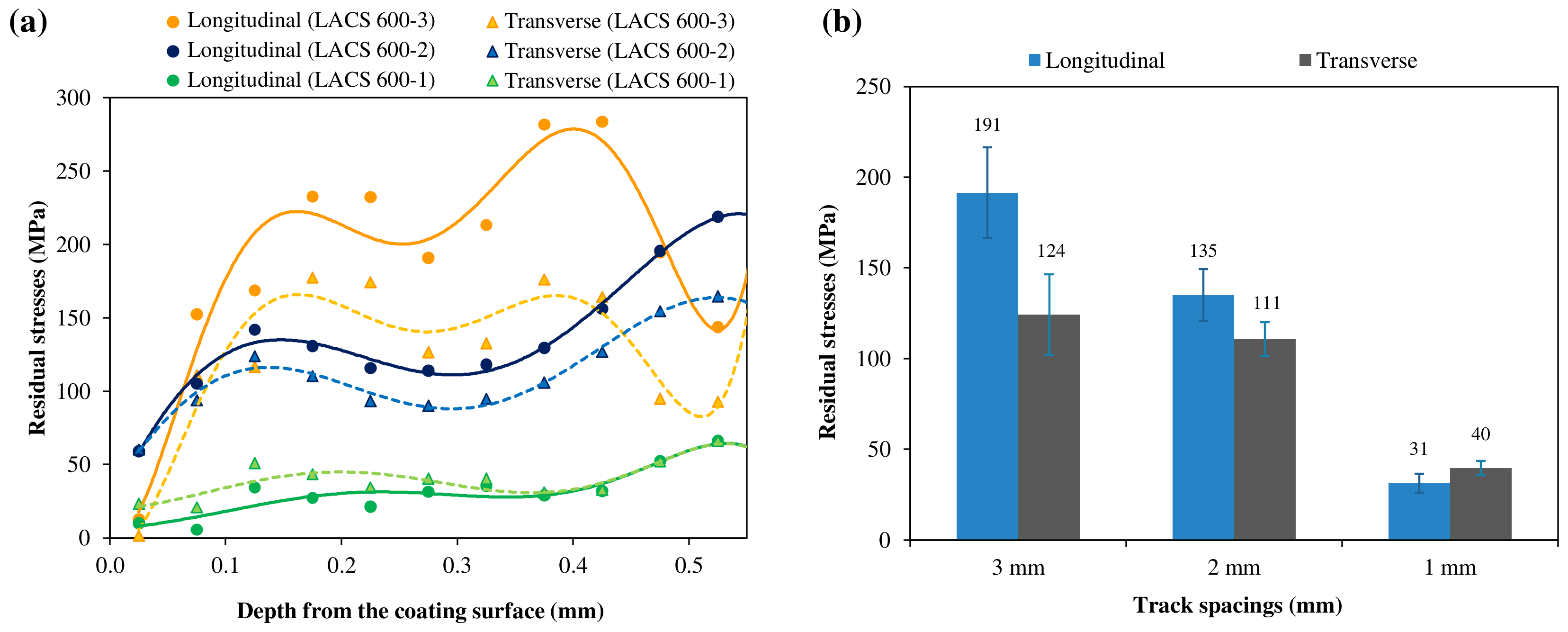
Figure 13.
Through-thickness residual stress distribution (longitudinal direction, LD) predicted using the analytical model (quenching dominant) [32,37,38].
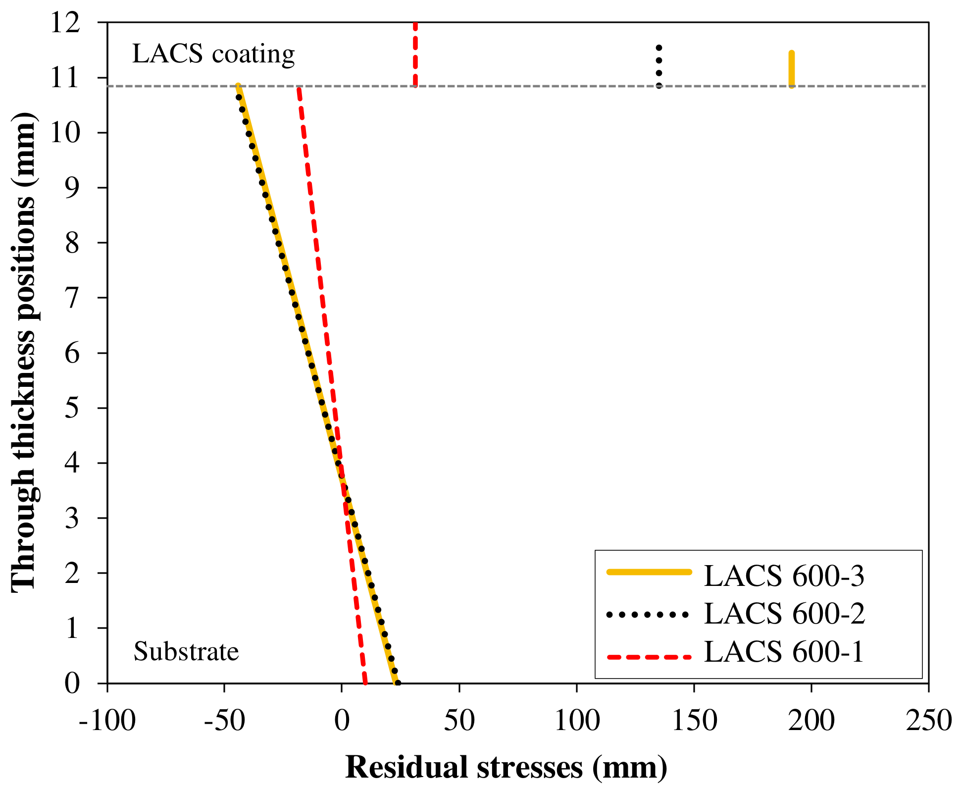
Figure 14.
SEM micrographs of post-deposition solution treatment and aged (STA) specimens showing the microstructure for coating sprayed using (a) the standard CS process, and LACS coatings with track spacings of (b) 1 mm, (c) 2 mm, and (d) 3 mm.
Figure 14.
SEM micrographs of post-deposition solution treatment and aged (STA) specimens showing the microstructure for coating sprayed using (a) the standard CS process, and LACS coatings with track spacings of (b) 1 mm, (c) 2 mm, and (d) 3 mm.
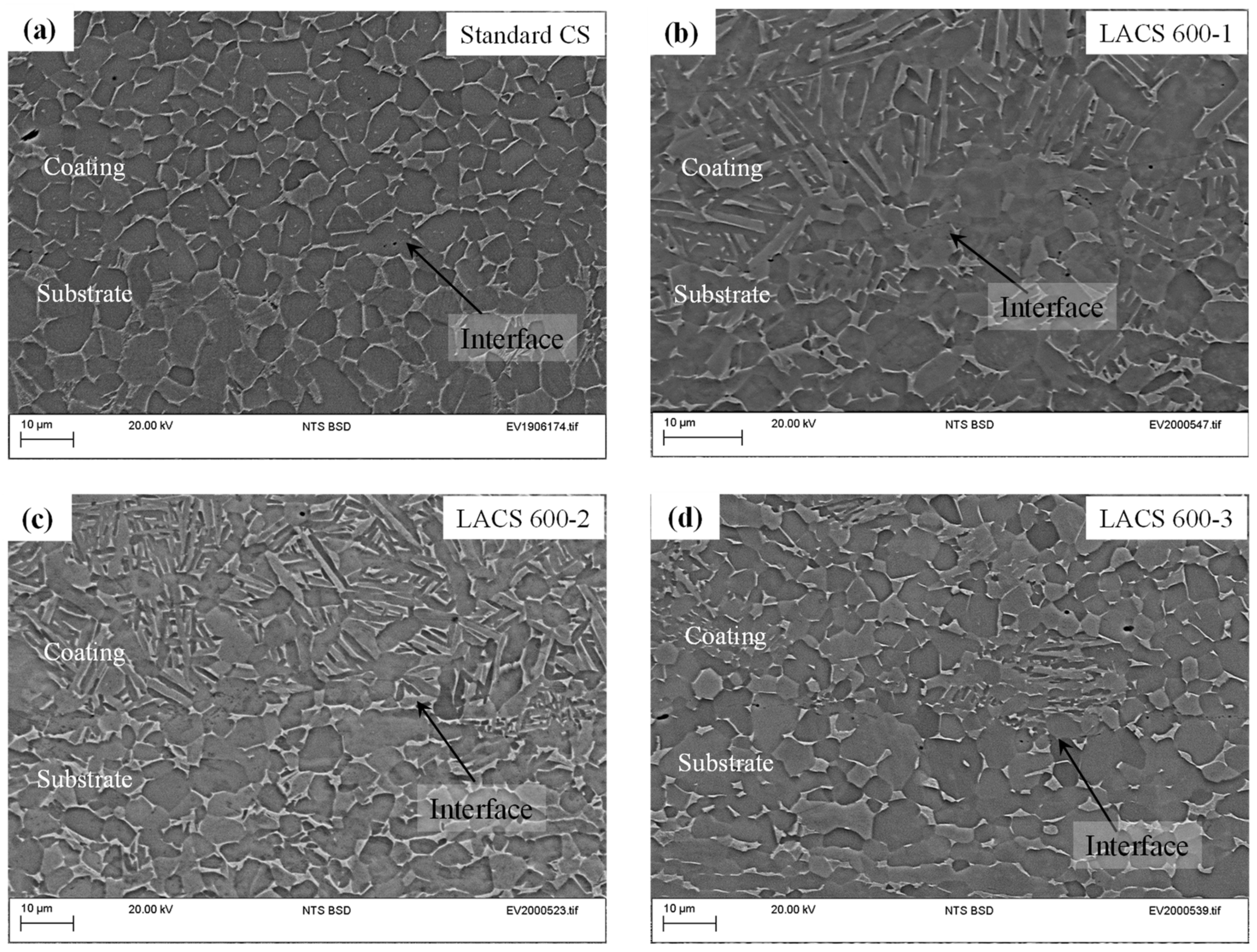
Table 3.
Specimens details for residual stress measurements and analysis from Phase 2 LACS trials.
| Specimen Name | Track Spacing (mm) | Coating Thickness (mm) | No. of Layers | Substrate Thickness (mm) | Toolpath Pattern | Scanning Speed (mm/s) |
|---|---|---|---|---|---|---|
| LACS 600-1 | 1 | 1.45 | 1 | 10.85 | Horizontal raster | 40 |
| LACS 600-2 | 2 | 0.86 | ||||
| LACS 600-3 | 3 | 0.60 |
Disclaimer/Publisher’s Note: The statements, opinions and data contained in all publications are solely those of the individual author(s) and contributor(s) and not of MDPI and/or the editor(s). MDPI and/or the editor(s) disclaim responsibility for any injury to people or property resulting from any ideas, methods, instructions or products referred to in the content. |
© 2023 by the authors. Licensee MDPI, Basel, Switzerland. This article is an open access article distributed under the terms and conditions of the Creative Commons Attribution (CC BY) license (https://creativecommons.org/licenses/by/4.0/).
Share and Cite
MDPI and ACS Style
Boruah, D.; McNutt, P.; Sharma, D.; Begg, H.; Zhang, X. Understanding the Effect of Substrate Preheating Temperature and Track Spacing on Laser Assisted Cold Spraying of Ti6Al4V. Metals 2023, 13, 1640. https://doi.org/10.3390/met13101640
AMA Style
Boruah D, McNutt P, Sharma D, Begg H, Zhang X. Understanding the Effect of Substrate Preheating Temperature and Track Spacing on Laser Assisted Cold Spraying of Ti6Al4V. Metals. 2023; 13(10):1640. https://doi.org/10.3390/met13101640
Chicago/Turabian StyleBoruah, Dibakor, Philip McNutt, Deepak Sharma, Henry Begg, and Xiang Zhang. 2023. "Understanding the Effect of Substrate Preheating Temperature and Track Spacing on Laser Assisted Cold Spraying of Ti6Al4V" Metals 13, no. 10: 1640. https://doi.org/10.3390/met13101640
Note that from the first issue of 2016, this journal uses article numbers instead of page numbers. See further details here.