Article

Improving Corrosion and Stress Corrosion Cracking Performance of Machined Biodegradable Alloy ZX20 by HF-Treatment

by
Evgeniy D. Merson
1,
Vitaliy A. Poluyanov
1,
Pavel N. Myagkikh
1,
Alexander S. Bunev
2,
Dmitri L. Merson
1,* and
Alexei Vinogradov
3
1
Institute of Advanced Technologies, Togliatti State University, 445020 Togliatti, Russia
2
Medicinal Chemistry Center, Togliatti State University, 445020 Togliatti, Russia
3
Magnesium Research Center, Kumamoto University, Kumamoto 860-8555, Japan
*
Author to whom correspondence should be addressed.
Metals 2023, 13(10), 1660; https://doi.org/10.3390/met13101660
Submission received: 6 September 2023 / Revised: 25 September 2023 / Accepted: 26 September 2023 / Published: 27 September 2023
(This article belongs to the Special Issue Future Trends in Metallic Biomaterials)

Abstract

:
The treatment with hydrofluoric acid (HF-treatment) was suggested to be an effective way of improving the corrosion resistance of Mg alloys, including Mg-Zn-Ca (ZX) ones used for biodegradable implants. However, the effect of the HF-treatment on the stress corrosion cracking (SCC) susceptibility of ZX alloys has not been reported yet, although this phenomenon can induce premature brittle failures of the metallic medical devices, and thus, it is critical for their in-service structural integrity. In the present study, the effect of the HF-treatment on the microstructure, cytotoxicity, corrosion rate, mechanical properties, and fracture and side surface characteristics of the as-cast ZX20 alloy were investigated with the use of scanning electron microscopy, immersion, and slow-strain rate tensile testing in Hanks’ solution and indirect cell viability tests. It is found that the HF-treatment exerts no cytotoxic effect and results in a significant reduction in corrosion rate (up to 6 times of magnitude) and SCC susceptibility indexes (up to 1.5 times of magnitude). The observed improvement of corrosion and SCC performance of the alloy by the HF-treatment is found to be attributed to three effects, including (i) formation of the protective surface film of MgF2, (ii) removal of surficial contaminations originating from sample preparation procedures, and (iii) dissolution of surficial secondary phase particles. The mechanism of corrosion and SCC in the specimens before and after the HF-treatment are discussed.

1. Introduction

Magnesium alloys are considered promising for applications such as biodegradable implants intended to dissolve in a living body after fulfilling their temporary support functions [1,2]. The primary advantage of utilizing bioresorbable implants is that there is no need for a second surgery, which is required to remove conventional permanent implants made from titanium and Co alloys or stainless steel, once the healing process is finished. Magnesium, being a nutrient element of the human body, plays an essential role in osteosynthesis and many other biological processes. Hence, magnesium exhibits exceptional biocompatibility, a fundamental requirement for biodegradable materials designed for medical purposes. Mg offers another benefit when compared to Ti, Co-Cr, and Fe alloys that are insoluble in human body liquids. This advantage stems from Mg’s low elastic modulus, which is similar to that of human bones. This similarity ensures that Mg implants used for repairing bone fractures do not induce the stress shielding phenomenon, which can impede the healing process. However, the mechanical characteristics of pure magnesium are far too low to meet the stringent requirements stipulated for biomedical devices. Therefore, alloying of Mg is practically unavoidable for improving its mechanical performance to acceptable standards. In turn, adding alloying elements such as Zn, Ca, Mn, etc., which are also approved for medical application, adversely affects the corrosion resistance, accelerating the biodegradation rate of Mg-based alloys [3]. This is attributed to the precipitation of noble intermetallic phases, which increase the galvanic corrosion rate of Mg matrix in body fluids [4,5]. Although biodegradation, referring to the resorption of material under interaction with the inner environment of a living body, is the intrinsic service function of biodegradable implants, the resorption rate must not exceed an adequate level. Otherwise, the too-fast reduction in the cross-section of the deployed implant may cause premature failure due to loss of the load-bearing capacity. Moreover, metallic materials—including Mg and its alloys, being subjected to mechanical stress and aggressive media such as body fluids, suffer from stress corrosion cracking (SCC), which can induce brittle fracture at stresses below the yield strength [6,7,8]. Thus, improving the corrosion and SCC resistance of biodegradable Mg alloys to aggressive body media is a vital and urgent task.
The design of the microstructure through alloying, heat treatment, and thermo-mechanical processing, on the one hand, and the protection of the surface using coatings and surface modification techniques, on the other, represent the two main approaches for enhancing the corrosion performance of biomedical Mg alloys. The optimization of the alloying content aims at controlling the number and composition of secondary phase particles or reducing the electrode potential difference between them and the Mg matrix [9,10,11,12,13,14,15] as well as selection of the optimal parameters of the heat treatments and thermomechanical processes, including extrusion, hot-rolling, equal channel angular pressing, and other severe plastic deformation techniques [16,17,18,19,20,21,22,23]. Various methods for protecting the Mg surface from corrosion, including conversion [24,25,26] and organic coatings [27,28], anodizing and plasma electrolytic oxidation [29,30], surface heat treatment, and plastic deformation [9,31,32], have been proposed so far. Comprehensive reviews considering the features of these methods can be found elsewhere [33,34,35]. In particular, the effectiveness of fluoride coatings in improving the corrosion properties of many Mg alloys was underlined in several studies [36]. The immersion of Mg into hydrofluoric (HF) acid is the simplest and most common way of producing the fluoride conversion coating; alternative techniques, including anodic [37], microarc [38], ultrasonic immersion [39], and molten salt [40] fluorination, do exist, however. The interaction of Mg with hydrofluoric acid results in the conversion of the surface Mg/MgO/Mg(OH)2 layer into the insoluble MgF2 film, which can considerably impede the anodic dissolution of the substrate metal in many aggressive aqueous solutions, including simulated body fluids (SBF) [36]. Taking into account that both in vitro and in vivo studies confirmed the overall good biocompatibility of fluoride coatings and the absence of adverse cytotoxic effects [41,42], immersion fluorination provides a simple pathway for the reliable protection of biomedical Mg alloys from accelerated premature biodegradation. The improvement of corrosion resistance of pure Mg after anodic or immersion fluoride coating was reported in several publications [37,41,43,44]. Drynda et al. demonstrated that the weight loss and corrosion current density of pure Mg and a wide range of Mg-xCa alloys were significantly reduced after fluorination conducted via 3 h boiling of the specimens in sodium hydroxide solution followed by 96 h immersion in 40% hydrofluoric acid [41]. In this study, it was also found that the MgF2 coating was cracked under 4-point bending tests in 5% NaCl solution. However, the cracked areas were quickly repassivated. Azlina et al. established the increase in corrosion resistance of pure Mg and Mg-1%Ca alloy after 24 h immersion in 48% HF acid [43]. Yan et al. found that immersion in a 50% hydrofluoric acid solution at 30 °C for 48 h increases the corrosion resistance of AZ31B alloy in simulated blood plasma without compromising the cytotoxicity of the alloy [38]. For the same alloy, Salman and Gouda reported the reduction in corrosion current density and corrosion potential in SBF with the increasing time of fluoridation from 0.5 to 8 h, which was performed by dipping the samples into molten Na[BF4] salt at 430 or 450 °C [40]. The authors also found pores in the fluoride coating, which were supposedly produced due to the interaction of the molten salt with the AlxMny secondary phase particles. Sun et al. observed that the corrosion resistance of the fluoride coating on the AZ31 alloy could be enhanced by ultrasonic treatment of the HF acid during immersion [39]. It has been proposed that the utilization of ultrasonic treatment aids in the release of hydrogen gas bubbles from the surface of the metal while it is immersed. This process subsequently promotes the creation of a fluoride layer that possesses fewer defects, such as micro-cracks and pores, in comparison to the layer formed through conventional immersion in HF acid without the aid from ultrasound. The corrosion rate of pure Mg, Mg-2Zn, Mg-2Zn-2Er, and Mg-3Zn-0.5Er in phosphate buffer saline solution reduced by a factor of 2 to 4 after immersion in a 40% hydrofluoric acid solution for 24 h at room temperature [45]. Gambaro et al. reported that the short-term corrosion rate of the Mg-2Y-1Mn-1Zn screws in Hanks’ buffered saline solution decreased from 0.84 ± 0.03 to 0.49 ± 0.06 mm/y after immersion in 40% HF acid [46]. Bita et al. demonstrated that sandblasting followed by immersion in the same acid for 24 h resulted in the remarkable increase in corrosion resistance of ZMX100 (Mg-1.3Zn-0.51Mn-0.38Ca) and ZMX410 (Mg-4.3Zn-0.62Mn-0.3Ca) alloys when compared to that of either their untreated or HF-treated or sandblasted counterparts [47]. The authors found the pores on the HF-treated surface of both alloys and explained their appearance by the release of hydrogen upon the initial contact of the substrate with the hydrofluoric acid solution. Gao et al. showed that fluoridation of the AZ61 powder in 40% HF acid provides an increase in corrosion performance of the alloy prepared from this powder by selective laser melting [48]. The corrosion rate of the alloy decreased with increasing time of immersion in HF acid up to 24 h, while further prolongation of the HF-treatment resulted in deterioration of corrosion resistance. Li et al. noticed the decrease in the corrosion rate of the biomedical screws machined from the extruded Mg-3.2 (wt.%) Zn-0.8 (wt.%) Zr alloy after soaking them with 20% hydrofluoric acid at 37 °C for 12 h. The reduction in the corrosion rate after HF-treatment was particularly pronounced at the first few days of submersion in SBF, while after 30 days, this effect was almost completely eliminated. The authors also observed that the mechanical properties of the alloy gradually reduced with the time of immersion in SBF. However, this reduction was notably lower for the HF-treated specimens. Notice that tensile testing was conducted in air after preliminary immersion in SBF; thus, the phenomenon referred to as pre-exposure SCC (PESCC) [49,50,51,52,53] was investigated. However, to the best of our knowledge, no papers exist reporting the effect of HF-treatment on true SCC, which is commonly assessed through the mechanical properties of biodegradable Mg alloys upon slow-strain rate tensile (SSRT) testing directly in SBF. Similarly, the effect of HF-treatment or fluoride coatings on corrosion and SCC behavior of Mg-Zn-Ca (ZX) alloys has not been reported so far. The alloys of ZX class have been recognized among the most promising materials for biodegradable implants [54,55,56,57]. Thus, the effect of the HF-treatment on corrosion and SCC performance of Mg-Zn-Ca alloy is of primary interest of the present study.
In addition, the present paper addresses several other issues, which have been poorly highlighted in the literature, concerning the effect of HF-treatment on the surface microstructure—notably secondary phase particles and surficial contaminating particles and films, which can be introduced from the sample preparation procedures, such as lath machining. For example, several studies showed that the HF-treatment resulted in the dissolution of secondary phases, including AlxMny in AZ31 [40,58] and Mg17Al12 in AZ91D [59] alloys, while some minor rare earth-containing dispersoids with La, Ce, and Nd in AZ31 [58] and Mg12(NdxGd1-x) in the alloy Electron 21 [59] remained virtually undissolved. The microstructure of the most of Mg-Zn-Ca alloys is featured by ternary and binary secondary phase particles including Mg2Ca, (Mg, Zn)2Ca, Ca2Mg6Zn3, Ca2Mg5Zn5, Ca3MgxZn15–x (4.6 ≤ x ≤ 12), etc. [60]; nevertheless, the effect of the HF-treatment on these phases has not been reported as yet.

2. Materials and Methods

2.1. Material

The alloy ZX20 of Mg-2%Zn-0.1%Ca (wt.%) nominal composition was received from the Solikamsk Experimental Metallurgical Plant “SOMZ” in the form of cast ingots of 65 mm diameter and 240 mm length. The chemical composition of the alloy determined by the optical emission spectrometer ARL 4460 OES (Thermo Fisher Scientific, Waltham, MA, USA) is provided in Table 1. The ingots were prepared by melting pure Mg (99.95%) in a steel crucible at 740 °C in a protective atmosphere of SF6, followed by cooling down to 720 °C, stirring for 5–10 min, adding metallic Zn and Ca, and pouring the melt into the steel mold preheated up to 300–350 °C and coated with a mold release agent. The ingots were homogenized in the electric furnace at 300 °C for 48 h and cooled in airflow. To protect the ingots from oxidation during annealing, they were wrapped in aluminum foil with sulfur powder. The time and temperature of homogenization were chosen to achieve the equilibrium microstructure with a homogeneous distribution of alloying elements on the one hand and to avoid melting the secondary phase on the other.

2.2. Specimens

The standard threaded round-shaped specimens with the gauge part of 6 mm diameter and 30 mm length, cylindrical samples of 6 mm diameter and 23 mm length, and disc-shaped samples of 9 mm diameter and 2 mm thickness were machined from the as-homogenized castings for mechanical, corrosion, and cell viability tests, respectively. The lath machining was conducted using the WC tool.

2.3. HF-Treatment

Prior to mechanical and corrosion tests, a set of samples for tensile, immersion, and cytotoxicity testing were soaked for 15 min in 40% hydrofluoric acid treated with an ultrasonic bath, followed by successive washing with distilled water and ethanol and drying with pressurized air. This procedure is referred to as the HF-treatment in what follows.

2.4. Mechanical Testing

The reference (as-homogenized) and HF-treated specimens were slow-strain rate tensile (SSRT) tested in laboratory air at 24 ± 1 °C as well as in Hanks’ solution (the chemical composition of the solution is provided in Table 2) at 37 ± 0.2 °C with automatic circulation of the corrosion medium and the pH adjustment controlled to be 7.4 ± 0.02 throughout the whole test. The detailed description and schematics of the experimental setup for tensile testing in corrosion solution with automatic temperature and pH adjustment can be found elsewhere [61]. The SSRT testing was performed at 5.6 × 10⁻⁶ s−1 nominal strain rate (0.01 mm/min traverse velocity) using an AG-X plus (Shimadzu, Kyoto, Japan) screw-driven testing machine. The mechanical properties were quantified in terms of the elongation to failure (EF), δ, ultimate tensile strength (UTS), σB, and SCC susceptibility indexes IEFSCC and IUTSSCC, indicating ductility and strength loss of the alloy and calculated according to Equations (1) and (2), respectively.
I S C C E F = δ 1 δ 2 δ 1 · 100 %
I S C C U T S = σ B 1 σ B 2 σ B 1 · 100 %
where, δ1 and σB1 are EF and UTS of the specimens tested in air, while δ2 and σB2 denote EF and UTS of the specimens tested in the corrosion solution. The SCC susceptibility indexes IEFSCC and IUTSSCC demonstrate the loss of mechanical properties attributed to the combined effect from the corrosive medium at a given temperature, pH level, etc., with respect to the standard mechanical properties, which are assessed in air, at room temperature. Thus, the direct effect of temperature on mechanical performance was not assessed individually, though it is supposed to be minor. Each test was conducted at least twice under the same conditions.
The HV0.01 microhardness was measured using the dynamic micro hardness tester DUH-211S (Shimadzu, Japan).

2.5. Microscopy

The microstructure, fracture, and side surface of the reference and HF-treated specimens were examined using a field-emission scanning electron microscope (SEM) SIGMA (Zeiss, Germany) equipped with in-lens the energy dispersive X-ray (EDX) detectors (EDAX, USA). The 20 kV accelerating voltage was used for obtaining the SEM images and EDX elemental maps. The microstructure of the samples before and after the HF-treatment was studied using the metallographic cross-sections, which were prepared by grinding with sandpapers up to #2500 grade, followed by polishing in water-free diamond suspension with 0.25 µm particles and, finally, by ion-polishing by argon ions using the IM4000 Plus (Hitachi, Japan) ion milling system. The longitudinal cross-sections of the tensile tested specimens before grinding and polishing were vacuum-mounted using SpeciFix resin and CitoVac (Struers, Denmark) vacuum impregnator. They were then platinum-coated using the G20 (GSEM, South Korea) compact magnetron SEM sputtering device.
The Ra roughness measurement of the machined surface of the alloy before and after HF-treatment was conducted with the use of a confocal laser scanning microscope Lext OLS4000 (Olympus) at ×400 magnification (×20 objective).

2.6. X-ray Diffraction

The samples were scanned via the Bragg–Brentano method using the Maxima XRD-7000S (Shimadzu, Japan) diffractometer (CuKα radiation, long thin focus (LFF) X-ray tube, tube current 40 mA, voltage 40 kV, scanning speed 0.5° min−1, step 0.01) in the angle range of 20–100 deg at 2theta. To improve the signal-to-noise ratio, a curved graphite monochromator was installed on the detector. Crystalline phases were identified using the Shimadzu PDF2 database. A search window of 0.2° by 2theta was set relative to the ICDD reference values.

2.7. Immersion Testing

The short-term corrosion rate of the reference and HF-treated samples was assessed by the weight loss (WL) and hydrogen evolution (HE) during 24 h immersion in Hanks’ solution. First, the samples were degreased in an ultrasonic bath with acetone and weighed and measured with a micrometer to evaluate geometrical parameters. Then, the samples were placed into the one-end-sealed burette filled with Hanks’ solution. The open ends of the burettes with the samples inside were immersed into the glass beaker filled with the same corrosion solution. The silicon-glass mesh, allowing free ion exchange and corrosion solution circulation, was mounted at the open end of the burettes to prevent the samples falling from the burettes. Thus, the hydrogen gas evolving from the samples during the test accumulated at the sealed end of the burette as the corrosion process proceeded. Automatic photo-imaging with a 1 image per hour rate allowed evaluation of the change in the volume of accumulated hydrogen along the test, thus providing a way to assess the kinetics of the corrosion process. The temperature and pH level of the corrosion solution were automatically adjusted throughout the experiment, similar to that developed to control the SCC tests in ref. [61]. After 24 h of the test, the total volume of accumulated hydrogen was measured; the samples were retrieved from the burettes, washed with ethanol, dried with compressed air, and immersed for 1 min into the standard 20% CrO3 + 1%AgNO3 aqueous solution to remove the corrosion products. After removing corrosion products, the samples were washed with ethanol, dried with compressed air, and weighed to evaluate the weight loss. The corrosion rate (in mm/year) by WL (Pw) and HE (PH) methods was calculated using Equations (3) and (4), respectively [62]:
PW = 2.1ΔW
PH = 1.085 VH
where, ΔW (mg/cm2/day) is the weight loss rate and VH (ml/cm2/day) is the hydrogen evolution rate.
Four identical samples of each kind (reference and HF-treated) were tested for reproducibility.

2.8. Cell Viability

2.8.1. Cell Culture

WI-26 VA4 lung fibroblast cells were purchased from the ATCC. WI-26 VA4 cells were maintained in MEM (Gibco, Glasgow, UK) supplemented with 10% fetal bovine serum (FBS, Gibco, UK), penicillin (100 UI mL−1), streptomycin (100 µg mL−1), and GlutaMax (2 mM, Gibco, UK). All cell line cultivation was performed under a humidified atmosphere of 95% air/5% CO2 at 37 °C. Subconfluent monolayers, in the log growth phase, were harvested by a brief treatment with TrypLE Express solution (Gibco, Glasgow, UK) in phosphate-buffered saline (PBS, Capricorn Scientific, Ebsdorfergrund, Germany) and washed three times in serum-free PBS. The number of viable cells was determined by trypan blue exclusion.

2.8.2. Extract Preparation

Sample extracts were prepared as follows. The disk samples were immersed in 1 mL MEM supplemented with 10% fetal bovine serum (FBS, Gibco, UK), penicillin (100 UI mL−1), streptomycin (100 µg mL−1), and GlutaMax (2 mM, Gibco, UK). The samples were then incubated in a humidified atmosphere with 95% humidity and 5% CO2 at 37 °C for 168 h. The supernatant was collected, and the obtained extracts were refrigerated at 4 °C and used within 3 days.

2.8.3. Antiproliferative Assay

The effects of the synthesized compounds on cell viability were determined using the MTT colorimetric test. All examined cells were diluted with the growth medium to 3.5 × 10⁴ cells per mL, and the aliquots (7 × 10³ cells per 200 μL) were placed in individual wells in 96-multiplates (Eppendorf, Hamburg, Germany) and incubated for 24 h. The next day, the cells were then treated with synthesized compounds separately at the final concentration 30 μM (or 300.0 μM concentration and diluted at various concentrations for determination of IC50) and incubated for 24 h at 37 °C in 5% CO2 atmosphere. After incubation, the cells were then treated with the 40 μL MTT solution (3-(4,5-dimethylthiazol-2-yl)-2,5-diphenyltetrazolium bromide, 5 mg mL−1 in PBS) and incubated for 4 h again. After this additional 4 h incubation, the medium with MTT was removed, and DMSO (150 μL) was added to dissolve the crystals formazan. The plates were shaken for 10 min. The optical density of each well was determined at 560 nm using a microplate reader GloMax Multi+ (Promega, Madison, WI, USA). Each of the tested compounds was evaluated for cytotoxicity in three separate experiments.

3. Results

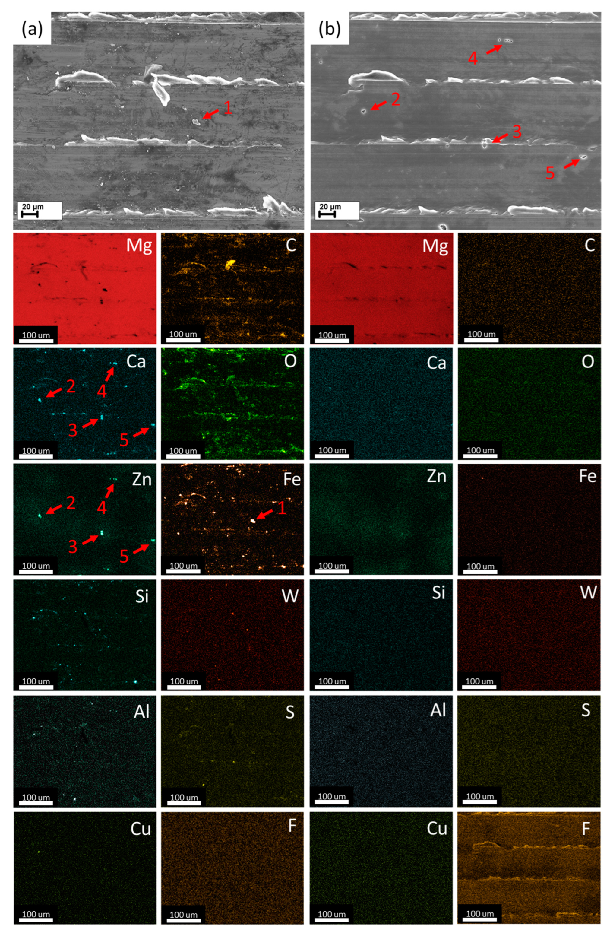
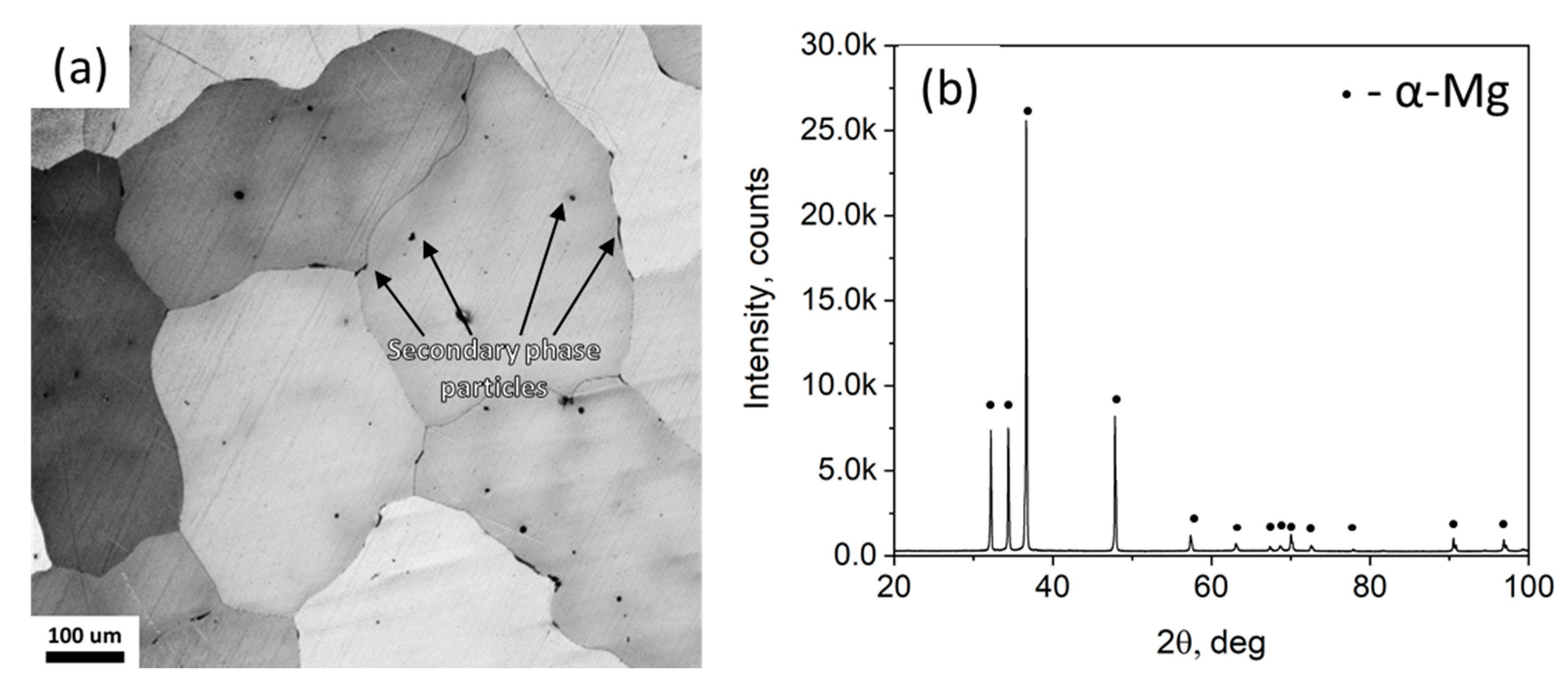
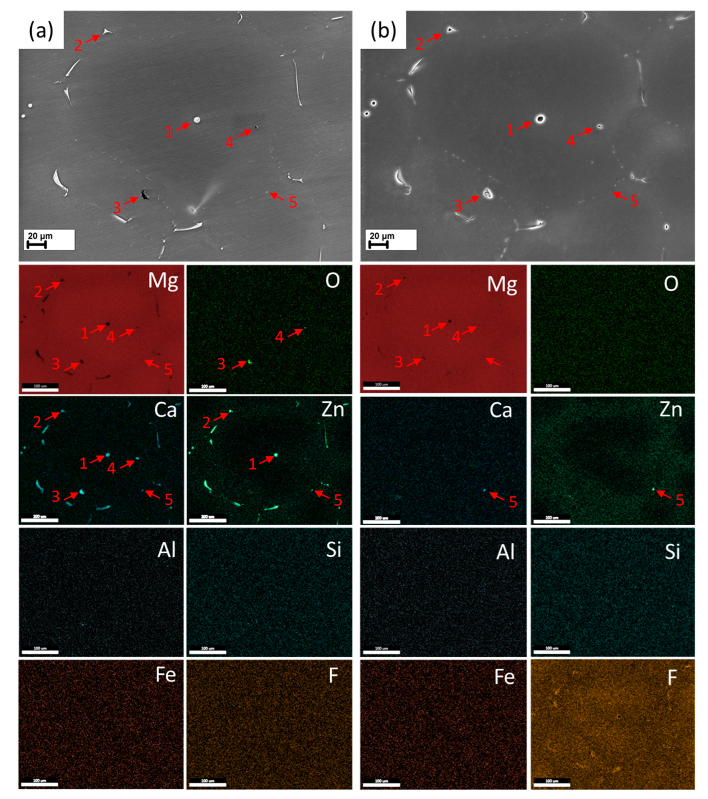
3.1. Effect of the HF-Treatment on the Side Surface and Microstructure

The same region on the axial side surface of the machined cylindrical samples used for immersion testing was investigated by SEM and EDX analysis before and after the HF-treatment. The samples, which were studied before the HF-treatment, were ultrasonically cleaned with acetone. The same cleaning procedure was used for all specimens before subjecting them to SCC and immersion testing. It is found that, before the HF-treatment, the side surface of the samples was severely contaminated by numerous particles and films of different chemical compositions incorporating such elements as C, Ca, O, Zn, Fe, Si, W, Al, S, Cu, etc., see Figure 1a. It should be stressed that the observed contaminations cannot be removed from the surface by the ultrasonic treatment in acetone. Obviously, the surface was most heavily contaminated during the machining of the samples. On the EDX map in Figure 1a, one can note the number of iron particles, which notably exceeds the number of Ca- and Zn-containing particles representing the main secondary phases in the ZX20 alloy. It can also be seen in the Fe map that there is a tendency for iron particles to segregate in a line-like manner along the machining grooves, thus suggesting that these particles originate from the cutting tool. Some of the particles are quite large, having a size up to a few microns, such as that indicated by arrow 1 in the SEM image and the Fe EDX map in Figure 1a. Due to the significantly higher electrode potential with respect to Mg, iron particles, as well as other particles containing Al, Si, W, Cu, etc., serve as local cathodic sites when submerged into the electrolyte, thus substantially accelerating anodic dissolution of surrounding Mg matrix of the alloy.
The EDX maps, Figure 1b, reveal that the HF-treatment eliminates contaminations from the surface. Just a very few residual particles of iron, Ca, and Zn can be found in the observed regions.
Instead of particles, the pronounced surface enrichment with fluorine is detected, suggesting that the fluoride film was formed on the surface. One can also note the small round-shape cavities, such as those indicated by arrows 2–6 on the SEM image in Figure 1b, which appeared on the surface after the HF-treatment. The juxtaposition of the SEM image in Figure 1b with EDX maps in Figure 1a reveals that the position of these cavities matches exactly with that of the particles enriched with Ca or Zn. Thus, the cavities likely originated from the dissolution of the microstructural secondary phase particles facing the surface. Other contaminating particles, e.g., the iron-reach one indicated by arrow 1 in Figure 1a, which had been introduced on the surface of the sample during preparation, dissolved during the HF-treatment without producing any damage to the surface.
It is found that the formation of cavities due to the HF-treatment notably affects the surface roughness of the samples. The twofold increase in Ra roughness after HF-treatment is measured for both the machined and polished surfaces, and the twofold difference in Ra is found between the machined and polished surfaces both in the reference and HF-treated states, c.f. Table 3.
To verify the suggestion made about the origin of the cavities found on the surface after the HF-treatment, and to establish the nature of the particles remaining on the surface after this treatment, a thorough SEM and EDX examination was conducted on the same region of the metallographic section before and after HF-treatment.
The optical metallographic examination showed that the microstructure of the as-homogenized ZX20 alloy is represented by large equiaxed grains of 220 µm average diameter with randomly distributed secondary phase particles arranged both in the grain interior and along the grain boundaries, Figure 2 and Figure 3. Due to the low volumetric fraction of the secondary phase, the XRD analysis failed to detect them properly, c.f. Figure 2b, and only α-Mg phase was identified.
The SEM examination of the ion-polished cross-sections revealed two types of particles with distinct morphological and chemical composition features dominating the microstructure. The majority of the particles belong to the first type, which is featured by the overall bright contrast with interspersed dark spots when imaged using the in-lens secondary electron detector in the SEM. The particles within the grain body have a spherical shape; see the particle indicated by arrow 1 in Figure 3a and its magnified image in Figure 4a. Conversely, the particles precipitated at the grain boundaries appear as either discontinuous chains of small equiaxed particles or extended Y-shaped aggregates decorating triple junctions, see the particle indicated by arrow 2 in Figure 3a and its magnified image in Figure 4b. The EDX maps and spectra provided in Figure 3a and Figure 4a,b indicate that the bright particles are composed of Mg, Zn, and Ca with the approximate Zn/Ca ratio of 2 and 3 for the particles spotted in grain interior and boundaries, respectively, Figure 4a,b. Thus, the particles precipitating along the grain boundaries contain more Zn and less Ca compared to those in the grain interior. One can also note in Zn EDX maps in Figure 3b that the solutionized Zn tends to segregate around grain boundaries, while the grain interior is depleted by Zn. According to the literature data, the observed chemical composition and morphological features of the first kind particles suggest that these are eutectic α-Mg + some of the ternary Mg-Zn-Ca phase, such as Ca2Mg6Zn3 or Ca3MgxZn15–x (4.6 ≤ x ≤ 12) [60].
The particles of the second kind are featured by the dark contrast with respect to the Mg matrix or the first kind particles; c.f., the particles indicated by arrows 3 and 4 in Figure 3a and their magnified images represented in Figure 4c,d. Similarly to the particles of the first kind, the particles of the second category are located either in the grain interior or at the grain boundaries. However, in contrast to the first group, the dark particles from the grain interior do not have a spherical appearance. Instead, polygonal or more complex irregular shapes can be recognized in association with the second group of particles. Furthermore, these particles are distinct from the first group by the chemical composition, which is featured by low Zn and high Ca content and the presence of oxygen, Figure 4c,d. The Zn/Ca ratio for these particles is about 0.1–0.4. Supposedly, the particles of the second kind represent the (Mg, Zn)2Ca phase, whose surface was oxidized due to contact with the atmosphere after polishing.
One can note that practically no particles other than those containing Mg, Zn, Ca, and O can be found in the region shown in Figure 2a. Therefore, the surface contamination exemplified in Figure 1a is attributed not to the microstructure but to the samples’ preparation procedure. Notably, machining can be blamed for that. It is fair to say that the microstructural particles belonging to some other minor groups with more complex chemical compositions, including Si, Al, Mn, S, and Fe, were occasionally observed in different regions of the metallographic cross-section. However, their population was negligible compared to that of the two major types of particles considered above.
The images shown in Figure 3a and Figure 4a–d refer to the as-homogenized microstructure. The corresponding SEM images with the elemental EDX maps of the same regions after the HF-treatment are provided in Figure 3b and Figure 4e–h. These illustrations make it evident that the HF-treatment results in the complete dissolution of most of the secondary phase particles of both kinds while the Mg matrix stays unaffected. The elemental maps provided in Figure 3b confirm that, except for the particle indicated by arrow 5 and enriched by Ca and Zn, all the particles observed in this region, Figure 4a, have been dissolved during the HF-treatment. The dissolution of the particles produces cavities with a geometry similar to that of the particles, as is clearly displayed in Figure 4e–h. The SEM and EDX examination of the undissolved particle referred to as “5” showed that this one had fuzzy boundaries and blurry bright contrast, Figure 5. These features suggest that this particle was probably located beneath the surface, so the above-lying Mg layer prevented the dissolution of this particle.
Thus, it is established that, except for the secondary phase Mg-Zn-Ca particles located beneath the Mg matrix, Figure 5, most of the surface contaminations introduced by sample preparation procedures, as well as surficial secondary phase particles, are removed from the surface of the machined specimens of the alloy ZX20 with the formation of the cavities on the surface.

3.2. Cell Viability

In vitro experiments (MTT assay [63], using the alloy extract in a complete growth medium) showed that both the reference and HF-treated samples of the ZX20 alloy exert no cytotoxic effect on investigated fibroblast cell cultures, as indicated by 121 ± 10 and 103 ± 13% percentage of surviving cells, respectively. The cell viability exceeding 100% for the reference specimens can be explained by the increase in metabolic activity under the action of an excess concentration of magnesium ions, which is observed when the cells are treated with the extract of the alloy.

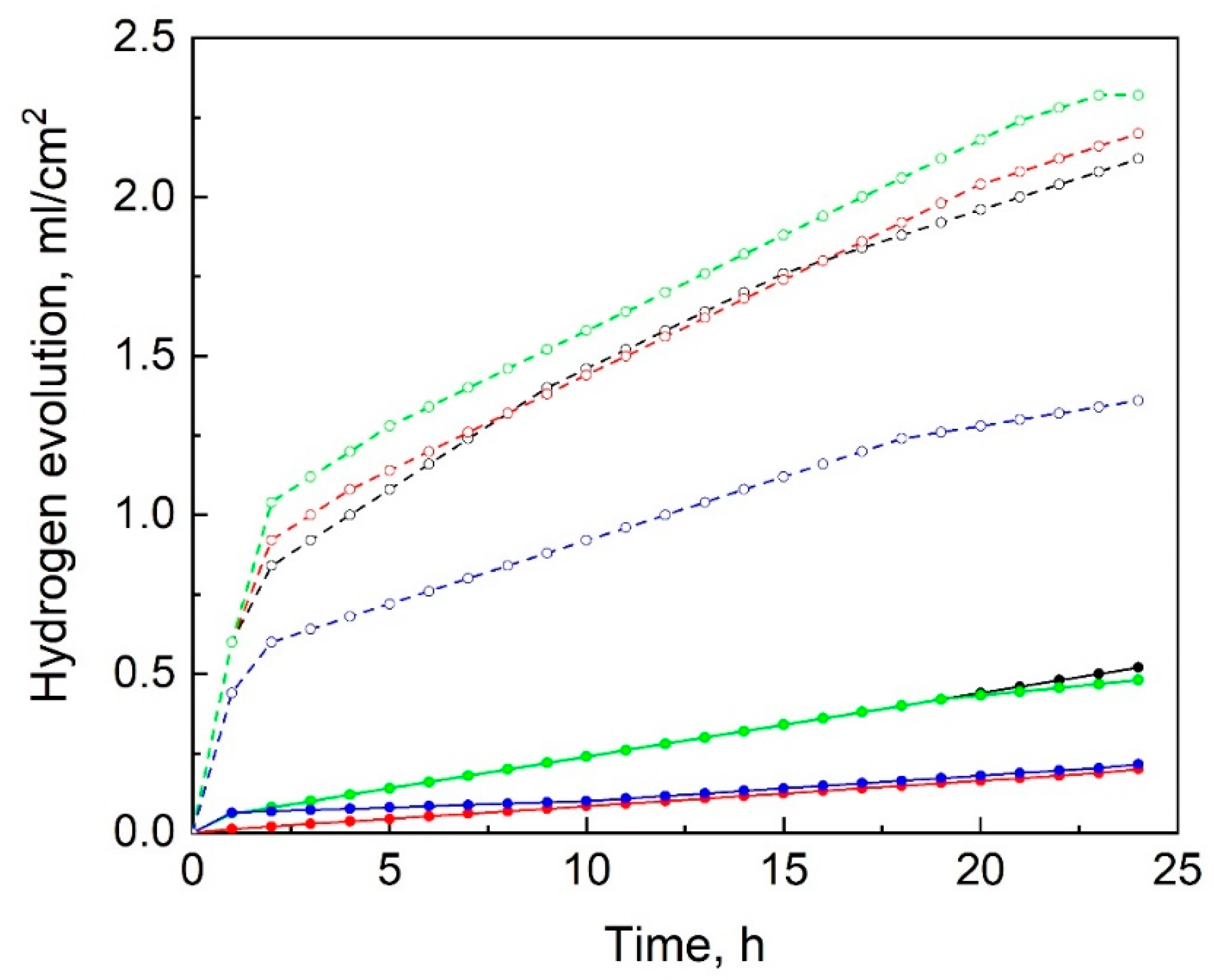
3.3. Immersion Testing

Immersion testing showed that the HF-treatment substantially reduced the corrosion rate of the alloy ZX20 in Hanks’ solution. The corrosion rate was measured both by weight loss as well as by volume of the evolved hydrogen gas, as summarized in Table 3. After the HF-treatment, the corrosion rate decreases more than by a factor of 3 from 2.7 ± 0.3 to 0.8 ± 0.1 mm/y if measured by the gravimetric method or by a factor of roughly 6 from 2.3 ± 0.4 to 0.4 ± 0.2 mm/y when measured by the hydrogen evolution method. The lower corrosion rate measured by the hydrogen evolution method is probably attributed to the fall-off particles from the corroded samples, which were not fully dissolved in the corrosion solution and, thus, contributed to the weight loss but not to the hydrogen evolution.
As can be seen in Figure 6, much less hydrogen has evolved from the HF-treated samples than from the reference ones. Furthermore, the hydrogen evolution curves for the reference samples exhibit a steep increase in the hydrogen volume evolved during the first three hours of the test, followed by a decrease in the hydrogen evolution rate. In contrast, hydrogen evolution from the HF-treated samples occurs at an almost constant rate throughout the test. Probably, the increased corrosion rate of the reference samples during the first three hours of the test can be attributed to the detrimental effect of contaminations, which, being attached to the samples’ surface, create many galvanic couples with the Mg matrix, accelerating its anodic dissolution. After the dissolution of the surface layer, the contaminating particles are either dissolved or fall off from the sample, resulting in the reduction in the corrosion rate to the steady value. However, it should be noted that, even at the steady state mode, the hydrogen evolution rate for the reference sample is notably higher than that for the HF-treated samples, as is indicated by the greater slopes of the hydrogen evolution curves for the reference samples compared to those of the HF-treated counterparts. This might be plausibly explained by the presence of the protective MgF2 film as well as by the absence of the secondary phase particles on the surface of the HF-treated samples.

3.4. Mechanical Testing

Mechanical testing showed that in the reference state, the alloy possesses 68 ± 2 HV0.01 microhardness, 165 ± 1 MPa ultimate tensile strength, and 18.2 ± 0.2% elongation to failure, see Table 3. It is found that the reference specimens tested in Hanks’ solution demonstrate remarkable SCC-susceptibility, which is manifested by their significantly lower elongation to failure and ultimate tensile strength compared to the specimens tested in air, Figure 7 and Table 3. The SCC-induced ductility and strength loss are found to be 53 ± 2 and 36 ± 3%, respectively. The HF-treatment remarkably reduces the SCC-susceptibility of the alloy: following the HF-treatment, the elongation at break and the ultimate tensile strength improve. The ductility and strength loss after the HF-treatment is about 1.5 times lower in comparison to the reference specimens. It is worth noting that the HF-treatment exerts an insignificant effect on the mechanical performance of the alloy ZX20 when tested in air. Thereby, the observed improvement in the SCC resistance should not be attributed to the effect of the HF-treatment on the mechanical properties (e.g., due to the formation of the surface fluoride film). Rather, the positive effect of the HF-treatment effect is associated with enhanced corrosion resistance, which is significantly benefited from the HF-treatment.

3.5. Microscopic Examination of the Tensile-Tested Specimens

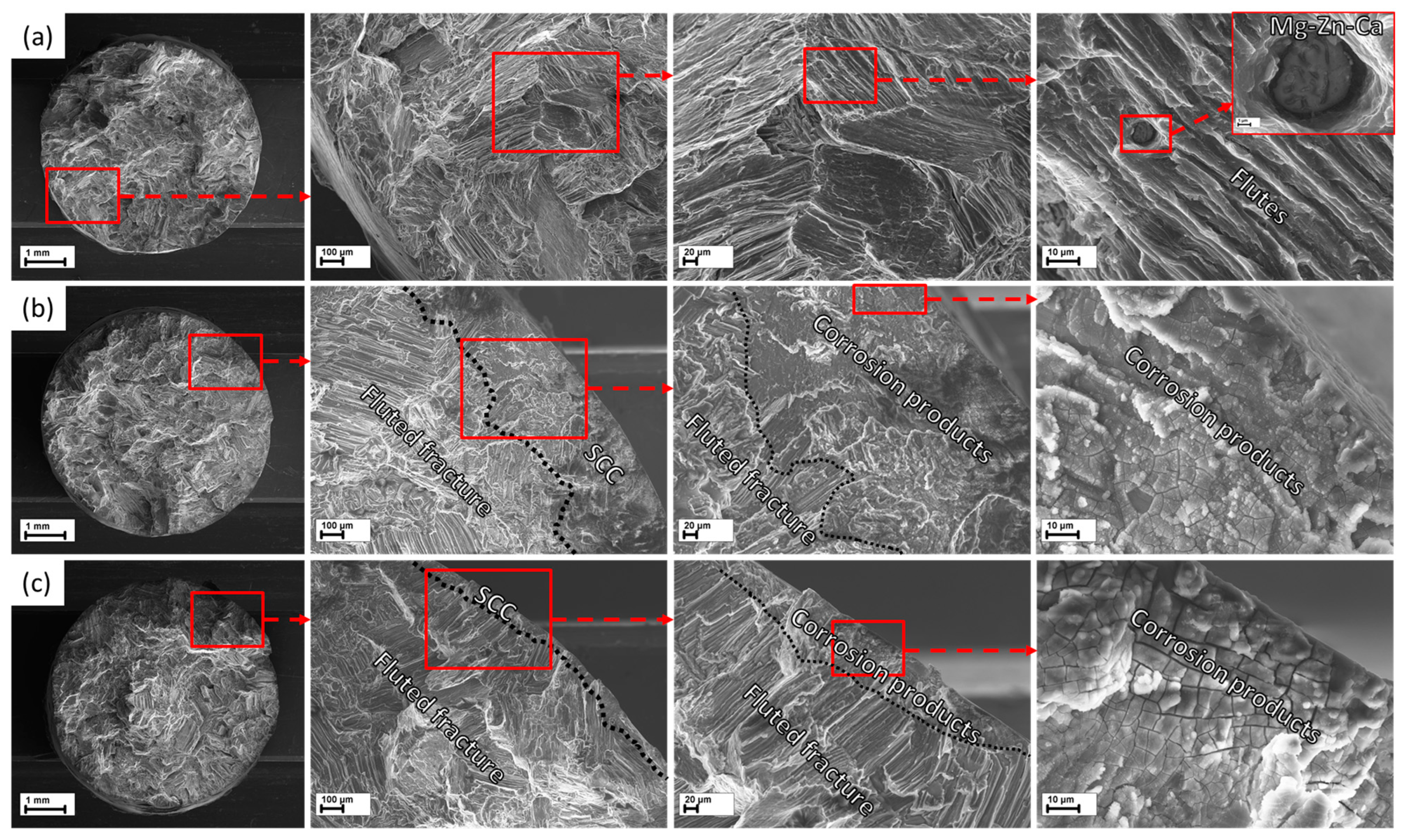
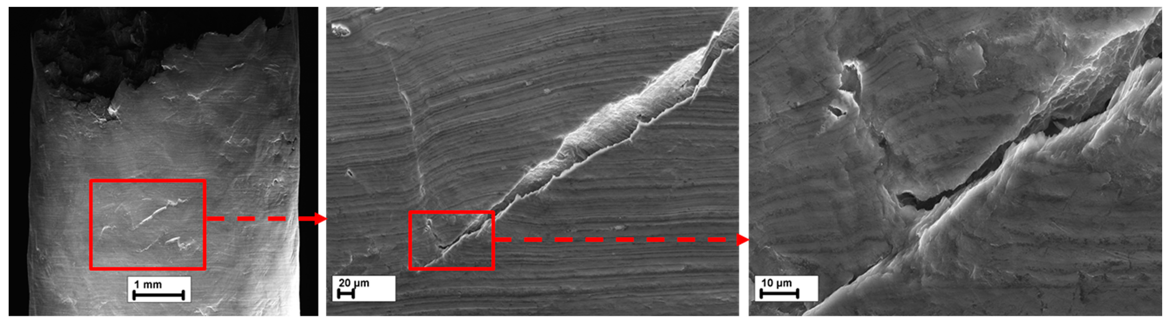
3.5.1. Fracture Surface

The fracture surface of the reference specimens tested in air is primarily represented by transgranular facets with a fluted morphology, which is characteristic of ductile fracture in as-cast Mg alloys tensile tested in inert environment, Figure 8a. Secondary phase particles can be occasionally seen on such facets. The fracture surface of both the reference and HF-treated specimens tested in Hanks’ solution demonstrates the peripheral annular region covered with corrosion products, Figure 8b,c. Apparently, this region was formed by SCC. The mechanism of crack growth responsible for the formation of this region is unclear because the exact morphology of the fracture surface is hidden under the corrosion products film, and it is severely damaged by corrosion. As the SCC extends from the side surface towards the center of the specimens, the corroded region is always followed by the region with dominating transgranular fluted facets similar to those observed in the reference specimens. The area and length of the corroded SCC zone preceding the fluted region are found to be smaller for the HF-treated specimens than for the reference ones. Supposedly, the fluted fracture surface in the specimens tested in Hanks’ solution is produced by the overload fracture, which occurs when the stress corrosion cracks reach the critical length corresponding to the critical stress intensity factor of brittle fracture.

3.5.2. Side Surface

The microscopic analysis showed that the side surface of all tested specimens contains cracks. The details of their morphology depend on the testing environment and the type of specimen, Figure 9, Figure 10 and Figure 11. Just a few cracks are found in the reference specimens tested in air. The majority of these cracks are inclined to the tensile axis at about 45° and exhibit ductile features such as voids and tear ridges, Figure 9.
In contrast, the side surface of the specimens tested in Hanks’ solution demonstrates numerous large cracks, which are oriented nearly perpendicularly to the tensile axis, Figure 10 and Figure 11. Furthermore, the cracks produced in the corrosion environment have a more brittle appearance than those for the specimens tested in air. The side surface of the reference specimens, as well as the inner surface of the side surface cracks, are fully covered with the cracked corrosion products layer of uneven thickness. The dense network of micro-cracks in the corrosion products layer can be seen on different view scales along the whole specimen’s surface contacted with the corrosion solution. These micro-cracks are different from the stress corrosion cracks in that they are shallower and can be oriented randomly to the tensile axis. However, as follows from Figure 10 and Figure 11, these micro-cracks serve as nuclei for the stress corrosion cracks produced during tensile testing.
In comparison with their reference counterparts, the HF-treated specimens contain a much smaller number of wide-open stress corrosion cracks, as can be seen in Figure 11. The areas free of both corrosion products and cracks can be found on the side surface of the HF-treated specimens. This is nicely illustrated by Figure 12, where it is seen that the tiny micro-cracks, tending to merge into the larger ones, appear only in the dark areas corresponding to the “islands” of corrosion products. The corresponding EDX maps showing the strong enrichment of these areas with oxygen, calcium, and phosphorus confirm the association of these dark regions with corrosion products. The abundance of these elements as well as chlorine is always observed in the areas with dense corrosion products film, e.g., around the cracks or corrosion pits such as those seen in the images labelled as “A” in Figure 10 and Figure 11, see the elemental maps. Thereby, the results of the side surface examination show that the micro-cracks in the corrosion products layer are the preferential nucleation sites for the stress corrosion cracks. Thus, due to the presence of the areas free of corrosion products, the side surface of the HF-treated specimens demonstrates a limited number of SCC nucleation sites compared to that of the reference specimens, explaining the lower susceptibility of the HF-treated specimens compared to that of the reference ones.

3.5.3. Cross-Sections

The microscopic examination of the longitudinal cross-sections prepared from the gauge parts of the tensile tested specimens revealed many secondary cracks propagating from the side surface towards the specimens’ bodies. SEM images with corresponding EDX elemental maps illustrating typical examples of such cracks in the reference and HF-treated specimens are provided in Figure 13a,b, respectively. The location of the grain boundaries in these images can be traced by the areas enriched with Zn as well as by the elongated ternary secondary phase particles identified by the bright contrast and high Zn and Ca concentration, which exhibit such a characteristic shape only when they precipitate along the grain boundaries (see Section 3.1). Evidently, in both the reference specimens and those treated with HF, it is observable that the cracks initiate at corrosion pits. These cracks then extend through the structures, spanning across the boundaries of α-phase grains as well as secondary phase particles. No cracks propagating along the grain boundaries were found. Furthermore, it seems that the secondary phase particles do not exert a significant effect on the propagation path or a crack nucleation site. Indeed, the crack nucleation always occurred outside of the secondary phase particles, whereas the crack path can run straight through the particles, as is evidenced by Figure 13b. In agreement with the results of fractographic and side surface examination, the images in Figure 13 show that the inner surfaces of the cracks are covered by corrosion products containing oxygen, chlorine, calcium, and phosphorus. Carbon observed within the cracks is inherited from the mounting resin used in the preparation procedures. One can also notice the region enriched with fluorine on the elemental map corresponding to the HF-treated specimen. The superposition of this map with the corresponding SEM image indicates that the presence of fluorine in this region is apparently attributed to the secondary phase particle, the surficial part of which was dissolved during the HF-treatment with the formation of MgF2. Interestingly, the largest part of this inclusion, lying deeply under the surface, was untouched by HF. The region enriched with fluorine also exhibits a high concentration of oxygen. However, the common components of corrosion products, including Ca, P, and Cl, are not found within this area.

4. Discussion

4.1. Effect of HF-Treatment on the Corrosion Process

Corrosion of magnesium and its alloys in aqueous solutions occurs in accordance with the following reactions:
Mg + 2H2O → Mg(OH)2 + ↑H2—the overall corrosion reaction
Mg → Mg2+ + 2e—the anodic partial reaction
2H2O + 2e → 2OH + ↑H2—the cathodic partial reaction
Mg2+ + 2OH → ↓Mg(OH)2—the deposition of hydroxide film on Mg surface
The presence of Cl anions in the electrolyte causes the breakdown of the protective hydroxide film with the formation of highly soluble MgCl2 by the following reaction:
Mg(OH)2 + 2Cl → MgCl2 + 2OH
The recursive cycles of (i) the formation of magnesium hydroxide, followed by (ii) its dissolution under reaction with Cl, (iii) formation of MgCl2, and (iv) its subsequent dissociation in water provides continuous anodic dissolution of Mg matrix.
In the case of Hanks’ solution, the corrosion process is more intricate due to the presence of additional compounds, such as Ca2+ cations and PO43− anions, which result in the formation of the layered corrosion products of various compositions, e.g., (Ca0.86, Mg0.14)10(PO4)6(OH)2 or Ca10(PO4)6(OH)2. The corrosion products layer containing such compounds has been suggested to act as a barrier decelerating corrosion to a greater extent than simple Mg hydroxide [64].
Most of the elements, e.g., Fe, Si, Al, Zn, W, etc., which were found in the secondary phase and contamination particles existing on the surface of the untreated reference samples, have a higher standard electrode potential with respect to Mg. Hence, they serve as cathodic sites, accelerating the anodic dissolution of the neighboring Mg matrix. Thus, the reference samples demonstrate a significantly higher corrosion rate compared to that of the HF-treated ones, which are free of surface contaminations and secondary phase particles. This is particularly true for the first few hours after submerging into a corrosion solution. The gradual dissolution of the surface layer of the matrix is probably accompanied by the fall off and dissolution of the contaminating particles, reducing the corrosion rate, as has been evidenced in the present study by the decrease in the hydrogen evolution rate. Furthermore, due to a relatively uniform distribution of the cathodic sites, the whole surface of the reference specimens contacted with the corrosion solution was severely attacked by corrosion and experienced the formation of extensive corrosion product films. In addition, numerous corrosion pits have been observed nucleating in the matrix sites out of Mg-Zn-Ca secondary phase particles. In contrast, the surface of the HF-treated specimens, along with the corrosion pits and products similar to those in the reference specimens, demonstrates the areas virtually undamaged by corrosion. It is firmly established in the present study that the HF-treatment causes the formation of fluoride surface film on the one hand and the almost complete dissolution of the contaminating and secondary phase particles at the surface on the other. However, some rare particles of complex composition as well as secondary phase particles located just beneath the surface were found unaffected by the HF-treatment. Thus, it can be suggested that although the greatest part of the Mg surface is protected by the MgF2 film, the retaining few particles undissolved during HF-treatment and serving as cathodic sites are still detrimental to the corrosion resistance, provoking the breakdown of the protective film and causing the formation of corrosion pits in the vicinity of these particles.

4.2. Effect of HF-Treatment on Stress Corrosion Cracking

During the SSRT testing in Hanks’ solution, the corrosion processes considered above are further complicated by the gradually increasing stress (and the associated strain) applied to the specimens. This strain may facilitate the breakdown of the protective films, including MgF2, Mg(OH)2, etc., deposited on the samples’ surface, thus providing access for corrosion solution to the bare metal. Indeed, as was shown in the present study, the corrosion products on the specimens’ surface are always totally covered by the extensive micro-crack network. It is questionable whether all these micro-cracks were produced during corrosion, e.g., due to the internal stress induced by the volumetric incompatibility between the Mg matrix and the corrosion products or due to external stress applied during SSRT testing. Nonetheless, there are no doubts that the SCC initiates at the micro-cracks originally formed in the corrosion products layer. Furthermore, the surface areas virtually free of corrosion products in the HF-treated specimens were always free of stress corrosion cracks either. The cross-sectional analysis showed that the nucleation and further propagation of the stress corrosion cracks always occurs in the Mg matrix and is virtually unaffected by the location of the secondary phase particles and grain boundaries. During propagation, the cracks can easily pass across the grain boundaries and particles. It has been reported that having a higher standard electrode potential with respect to Mg, the ternary Mg-Zn-Ca phase serves as an obstacle for corrosion pits extending through the Mg matrix via anodic dissolution [3]. Therefore, the fact that the cracks can easily grow across the ternary phase particles, c.f., Figure 13b, likely suggests that the crack growth mechanism other than anodic dissolution can be responsible for transgranular SCC in the ZX20 alloy. It is generally believed that the SCC of Mg alloys can be governed by hydrogen evolving during corrosion, causing hydrogen-assisted cracking. However, controversial observations have been reported on this issue so far, challenging the importance and exact role of hydrogen in the SCC mechanism in Mg. The details of this aspect can be found elsewhere [49,53,65,66,67].
The crack path and other features of SCC observed in the present study were similar for the reference and HF-treated specimens, underlying the similarity in the governing mechanisms of crack nucleation and growth. Thus, it can be suggested that regardless of the exact mechanism of crack growth, the higher SCC resistance of the HF-treated specimens is likely attributed to their higher corrosion resistance. In conformity with multiple studies [68,69,70,71], we found that SCC preferably nucleates at corrosion pits serving as local stress risers. Since the reference specimens suffered from greater corrosion damage associated with a greater number and deeper corrosion pits, they also demonstrated higher susceptibility to SCC than the HF-treated specimens.

4.3. The Methodological Aspects That Need Attention

The preparation of the specimens for the various kinds of laboratory tests, such as immersion and SCC testing, implying interaction of the specimens with an aggressive environment, commonly comprises many steps from cutting and machining to polishing, degreasing and cleaning. Most of these operations can contaminate the specimens’ surface with various types of particles and films, including those found in the present study. For example, the lath and milling machining can introduce the iron and tungsten particles from the cutting tools. Electric discharge machining leaves the particles of the cutting wire, such as brass and molybdenum. Grinding supplies the abrasive particles, e.g., SiO2 or Al2O3. Most of these contaminating particles contain elements having higher standard electrode potential with respect to the Mg matrix. Thus, these particles serve as cathodic sites, which can considerably increase the corrosion rate, especially at the first stage of the corrosion test, affecting the apparent corrosion resistance of the alloy. As was shown in the present study, the finish polishing with ion-sputtering could remove most of the contaminations. However, these procedures are inconvenient, too laborious, costly, and often inapplicable for large-scale specimens of complex shape. Furthermore, the same issue concerns not only the specimens used in laboratory testing campaigns but also the final products, e.g., the biodegradable Mg-based implants, the manufacturing process of which includes various technological operations similar to those used for the preparation of the specimens. The proper mechanical polishing of the implants in the complex form, such as screws or plates with holes, is practically impossible, while ion-sputtering might be costly and ineffective. We demonstrated that the HF-treatment not only effectively removes the contaminating particles and secondary phase particles from the surface of the Mg alloy ZX20 but also produces a highly efficient protective MgF2 film, which exerts an extra positive effect on the corrosion and SCC performance of the alloy. Considering that this treatment does not affect the cytotoxicity of the alloy and can be equally well used for specimens, implants and other products both of simple and complex shapes, it is deemed that the HF-treatment has high potential to be used as a final step in preparation of the specimens and implants made of biodegradable Mg alloys.

5. Conclusions

The machined specimens of the as-homogenized ZX20 alloy were subjected to immersion and SSRT testing in air and in Hanks’ solution in the HF-treated and in the reference untreated (as-homogenized) states. The cytotoxicity associated with the HF-treatment was assessed by the indirect cell viability tests. The side surface and microstructure of the untested specimens before and after the HF-treatment as well as cross-sections, fracture, and side surfaces of the reference and HF-treated specimens after SSRT testing, was performed using SEM and EDX analyses. The main findings and conclusions obtained during the present study are as follows.
  • The immersion and SSRT testing showed that ultrasonic 15-min-long HF-treatment does not affect the cytotoxicity and significantly improves corrosion and SCC resistance of the machined specimens of the ZX20 alloy, as is witnessed by the decrease in their corrosion rate from 2.7 ± 0.3 down to 0.8 ± 0.1 mm/year and by reduction in their ductility and strength loss from 53 ± 2 to 36 ± 5% and from 36 ± 3 to 20 ± 3% respectively.
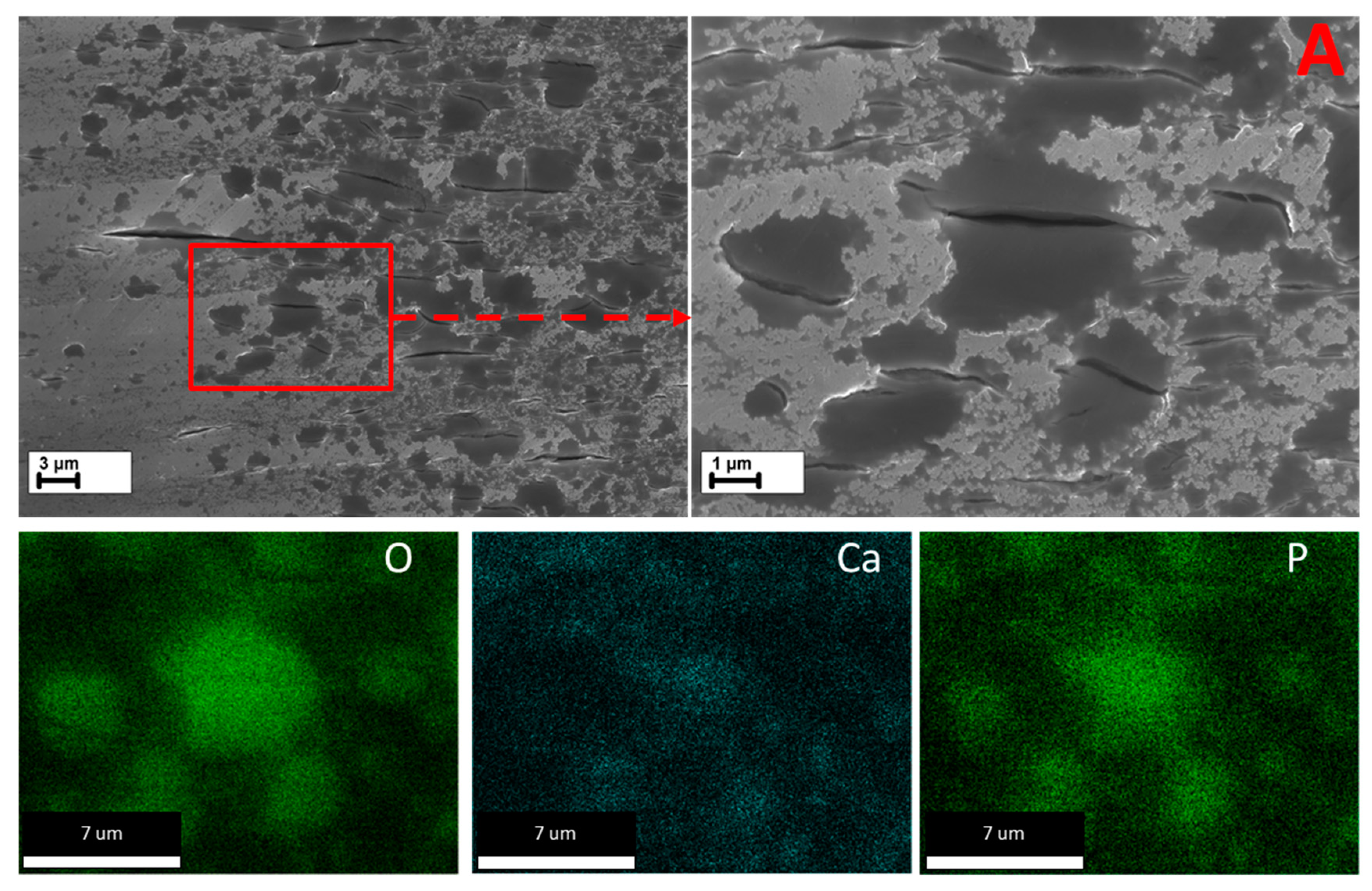
  • According to the side surface and microstructure examinations, the observed increase in corrosion and SCC performance is associated with the three effects induced by the HF-treatment, namely the following: (1) formation of the MgF2 protective film, (2) removal of the surficial contaminating particles and films originated from the sample preparation procedures such as machining, and (3) removal of the surficial secondary phase particles including binary (Mg, Zn)2Ca and ternary Ca2Mg6Zn3 ones.
  • In both the reference and HF-treated specimens, the mechanism of SCC was similar in that the cracks originated in the side surface corrosion products layer at the bottom of corrosion pits and propagated across the bodies and boundaries of the grains and secondary phase particles with no pronounced influence from the latter on the path and origination points of the crack.
  • The increase in the SCC resistance of the HF-treated specimens is chiefly attributed to their increased corrosion resistance, providing fewer corrosion pits and products and, thus, reducing potential nucleation sites for stress corrosion cracks.
  • Exerting no cytotoxic effect, the HF-treatment has been proven to be used as an efficient finishing preparation procedure prior to corrosion or SCC testing as well as before sterilization or coating of the biodegradable implants made of Mg alloys.

Author Contributions

Conceptualization, E.D.M., D.L.M. and A.V.; Formal analysis, E.D.M., V.A.P., P.N.M. and A.S.B.; Funding acquisition, E.D.M.; Investigation, E.D.M., V.A.P., P.N.M. and A.S.B.; Methodology, E.D.M., V.A.P., P.N.M. and A.S.B.; Project administration, D.L.M.; Resources, D.L.M.; Supervision, D.L.M. and A.V.; Writing—original draft, E.D.M., A.S.B. and A.V.; Writing—review & editing, E.D.M., A.S.B. and A.V. All authors have read and agreed to the published version of the manuscript.

Funding

This research was funded by the Russian Science Foundation, grant-in-aid No. 21-79-10378.

Data Availability Statement

Experimental data obtained by the authors are available from the corresponding author upon reasonable request.

Acknowledgments

The authors acknowledge the Solikamsk Experimental Metallurgical Plant “SOMZ” for providing as-cast ZX20 alloy.

Conflicts of Interest

The authors declare no conflict of interest.

References

  1. Ali, M.; Hussein, M.A.; Al-Aqeeli, N. Magnesium-Based Composites and Alloys for Medical Applications: A Review of Mechanical and Corrosion Properties. J. Alloys Compd. 2019, 792, 1162–1190. [Google Scholar] [CrossRef]
  2. Banerjee, P.C.; Al-Saadi, S.; Choudhary, L.; Harandi, S.E.; Singh, R. Magnesium Implants: Prospects and Challenges. Materials 2019, 12, 136. [Google Scholar] [CrossRef] [PubMed]
  3. Atrens, A.; Shi, Z.; Mehreen, S.U.; Johnston, S.; Song, G.L.; Chen, X.; Pan, F. Review of Mg Alloy Corrosion Rates. J. Magnes. Alloys 2020, 8, 989–998. [Google Scholar] [CrossRef]
  4. Esmaily, M.; Svensson, J.E.; Fajardo, S.; Birbilis, N.; Frankel, G.S.; Virtanen, S.; Arrabal, R.; Thomas, S.; Johansson, L.G. Fundamentals and Advances in Magnesium Alloy Corrosion. Prog. Mater. Sci. 2017, 89, 92–193. [Google Scholar] [CrossRef]
  5. Atrens, A.; Song, G.L.; Shi, Z.; Soltan, A.; Johnston, S.; Dargusch, M.S. Understanding the Corrosion of Mg and Mg Alloys; Elsevier: Amsterdam, The Netherlands, 2018; ISBN 9780128098943. [Google Scholar]
  6. Song, Y.; Fu, H.; Wang, Z.; Yang, P. Stress Corrosion Cracking of Magnesium Alloys: Mechanism, Influencing Factors, and Prevention Technology. Mater. Rep. 2019, 33, 834–840. [Google Scholar] [CrossRef]
  7. Winzer, N.; Atrens, A.; Song, G.; Ghali, E.; Dietzel, W.; Kainer, K.U.; Hort, N.; Blawert, C. A Critical Review of the Stress Corrosion Cracking (SCC) of Magnesium Alloys. Adv. Eng. Mater. 2005, 7, 659–693. [Google Scholar] [CrossRef]
  8. Jafari, S.; Harandi, S.E.; Singh Raman, R.K. A Review of Stress-Corrosion Cracking and Corrosion Fatigue of Magnesium Alloys for Biodegradable Implant Applications. JOM 2015, 67, 1143–1153. [Google Scholar] [CrossRef]
  9. Gao, C.; Li, S.; Liu, L.; Bin, S.; Yang, Y.; Peng, S.; Shuai, C. Dual Alloying Improves the Corrosion Resistance of Biodegradable Mg Alloys Prepared by Selective Laser Melting. J. Magnes. Alloys 2021, 9, 305–316. [Google Scholar] [CrossRef]
  10. Kiani, F.; Lin, J.; Vahid, A.; Munir, K.; Wen, C.; Li, Y. Microstructures, Mechanical Properties, Corrosion, and Biocompatibility of Extruded Mg-Zr-Sr-Ho Alloys for Biodegradable Implant Applications. J. Magnes. Alloys 2023, 11, 110–136. [Google Scholar] [CrossRef]
  11. Cao, X.; Li, C.; Wu, B.; Liang, M. Research of Dynamic Corrosion Behavior, Microstructure, and Biocompatibility of Mg–Zn–Ca–Zr Alloys in Simulated Body Fluid Solution Induced by Zn Element Addition. Adv. Eng. Mater. 2023, 25, 2201402. [Google Scholar] [CrossRef]
  12. Zhu, G.; Lyu, S.; Shen, G.; Tian, L.; Chen, M. Effect of the Microstructure Parameters on the Mechanical Properties and Corrosion Behavior of Mg Alloys with High Zn or Ca Content. J. Mater. Sci. 2023, 58, 12373–12390. [Google Scholar] [CrossRef]
  13. Cihova, M.; Martinelli, E.; Schmutz, P.; Myrissa, A.; Schäublin, R.; Weinberg, A.M.; Uggowitzer, P.J.; Löffler, J.F. The Role of Zinc in the Biocorrosion Behavior of Resorbable Mg–Zn–Ca Alloys. Acta Biomater. 2019, 100, 398–414. [Google Scholar] [CrossRef] [PubMed]
  14. Roh, H.J.; Park, J.; Lee, S.H.; Kim, D.H.; Lee, G.C.; Jeon, H.; Chae, M.; Lee, K.S.; Sun, J.Y.; Lee, D.H.; et al. Optimization of the Clinically Approved Mg-Zn Alloy System through the Addition of Ca. Biomater. Res. 2022, 26, 41. [Google Scholar] [CrossRef] [PubMed]
  15. Istrate, B.; Munteanu, C.; Bălțatu, M.S.; Cimpoeșu, R.; Ioanid, N. Microstructural and Electrochemical Influence of Zn in MgCaZn Biodegradable Alloys. Materials 2023, 16, 2487. [Google Scholar] [CrossRef]
  16. Shiri, M.; Jafari, H. Effect of Extrusion Temperature and Extrusion Ratio on Microstructure and Biodegradation Behavior of Mg-4.5Zn Binary Alloy. JOM 2019, 71, 4705–4714. [Google Scholar] [CrossRef]
  17. Incesu, A.; Gungor, A. Mechanical Properties and Biodegradability of Mg–Zn–Ca Alloys: Homogenization Heat Treatment and Hot Rolling. J. Mater. Sci. Mater. Med. 2020, 31, 123. [Google Scholar] [CrossRef]
  18. Peron, M.; Skaret, P.C.; Fabrizi, A.; Varone, A.; Montanari, R.; Roven, H.J.; Ferro, P.; Berto, F.; Torgersen, J. The Effect of Equal Channel Angular Pressing on the Stress Corrosion Cracking Susceptibility of AZ31 Alloy in Simulated Body Fluid. J. Mech. Behav. Biomed. Mater. 2020, 106, 103724. [Google Scholar] [CrossRef]
  19. Kulyasova, O.B.; Khudododova, G.D.; Dyakonov, G.S.; Zheng, Y.; Valiev, R.Z. Effect of Microstructure Refinement on the Corrosion Behavior of the Bioresorbable Mg-1Zn-0.2Ca and Mg-1Ca Alloys. Materials 2022, 15, 6749. [Google Scholar] [CrossRef]
  20. Alateyah, A.I.; Alawad, M.O.; Aljohani, T.A.; El-Garaihy, W.H. Influence of Ultrafine-Grained Microstructure and Texture Evolution of ECAPed ZK30 Magnesium Alloy on the Corrosion Behavior in Different Corrosive Agents. Materials 2022, 15, 5515. [Google Scholar] [CrossRef]
  21. Bin, S.J.B.; Fong, K.S.; Chua, B.W.; Gupta, M. Development of Biocompatible Bulk MgZnCa Metallic Glass with Very High Corrosion Resistance in Simulated Body Fluid. Materials 2022, 15, 8989. [Google Scholar] [CrossRef]
  22. Shaban, M.; Alateyah, A.I.; Alsharekh, M.F.; Alawad, M.O.; BaQais, A.; Kamel, M.; Alsunaydih, F.N.; El-Garaihy, W.H.; Salem, H.G. Influence of ECAP Parameters on the Structural, Electrochemical and Mechanical Behavior of ZK30: A Combination of Experimental and Machine Learning Approaches. J. Manuf. Mater. Process. 2023, 7, 52. [Google Scholar] [CrossRef]
  23. Heidari, E.; Esmaeili, Y.; Boutorabi, S.M.A. Effect of Solution Treatment on the Microstructure and Bio-Corrosion Behavior of Magnesium Cast Alloy. Int. J. Met. 2023, 1–11. [Google Scholar] [CrossRef]
  24. Popa, M.; Stefan, L.M.; Prelipcean, A.M.; Drob, S.I.; Anastasescu, M.; Calderon Moreno, J.M. Inhibition of Mg Corrosion in Physiological Fluids by Carbonate Coating. Corros. Sci. 2022, 209, 110775. [Google Scholar] [CrossRef]
  25. Chiu, C.; Lu, C.-T.; Chen, S.H.; Ou, K.L. Effect of Hydroxyapatite on the Mechanical Properties and Corrosion Behavior of Mg-Zn-Y Alloy. Materials 2017, 10, 855. [Google Scholar] [CrossRef] [PubMed]
  26. Peng, F.; Li, H.; Wang, D.; Tian, P.; Tian, Y.; Yuan, G.; Xu, D.; Liu, X. Enhanced Corrosion Resistance and Biocompatibility of Magnesium Alloy by Mg-Al-Layered Double Hydroxide. ACS Appl. Mater. Interfaces 2016, 8, 35033–35044. [Google Scholar] [CrossRef] [PubMed]
  27. Antoniac, I.; Popescu, D.; Zapciu, A.; Antoniac, A.; Miculescu, F.; Moldovan, H. Magnesium Filled Polylactic Acid (PLA) Material for Filament Based 3D Printing. Materials 2019, 12, 719. [Google Scholar] [CrossRef]
  28. Gaur, S.; Singh Raman, R.K.; Khanna, A.S. In Vitro Investigation of Biodegradable Polymeric Coating for Corrosion Resistance of Mg-6Zn-Ca Alloy in Simulated Body Fluid. Mater. Sci. Eng. C 2014, 42, 91–101. [Google Scholar] [CrossRef]
  29. Moreno, L.; Mohedano, M.; Arrabal, R.; Matykina, E. Development and Screening of (Ca-P-Si-F)-PEO Coatings for Biodegradability Control of Mg-Zn-Ca Alloys. J. Magnes. Alloys 2022, 10, 2220–2237. [Google Scholar] [CrossRef]
  30. Zhang, X.; Zhang, Y.; Lv, Y.; Dong, Z.; Yang, L.; Zhang, E.; Hashimoto, T.; Zhou, X. PEO Coating on Mg-Ag Alloy: The Incorporation and Release of Ag Species. J. Magnes. Alloys 2022, 11, 2182–2195. [Google Scholar] [CrossRef]
  31. Yao, X.; Tang, J.; Zhou, Y.; Atrens, A.; Dargusch, M.S.; Wiese, B.; Ebel, T.; Yan, M. Surface Modification of Biomedical Mg-Ca and Mg-Zn-Ca Alloys Using Selective Laser Melting: Corrosion Behaviour, Microhardness and Biocompatibility. J. Magnes. Alloys 2021, 9, 2155–2168. [Google Scholar] [CrossRef]
  32. Liu, C.; Zheng, H.; Gu, X.; Jiang, B.; Liang, J. Effect of Severe Shot Peening on Corrosion Behavior of AZ31 and AZ91 Magnesium Alloys. J. Alloys Compd. 2019, 770, 500–506. [Google Scholar] [CrossRef]
  33. Santos, V.; Uddin, M.; Hall, C. Mechanical Surface Treatments for Controlling Surface Integrity and Corrosion Resistance of Mg Alloy Implants: A Review. J. Funct. Biomater. 2023, 14, 242. [Google Scholar] [CrossRef] [PubMed]
  34. Zhang, Y.; Liu, W.; Liu, Y.; Zhang, M.; Tian, Y.; Chen, L. Research Progress on Corrosion Behaviors and Improvement Methods of Medical Degradable Mg−Based Alloys. Metals 2022, 13, 71. [Google Scholar] [CrossRef]
  35. Wei, L.; Gao, Z. Recent Research Advances on Corrosion Mechanism and Protection, and Novel Coating Materials of Magnesium Alloys: A Review. RSC Adv. 2023, 13, 8427–8463. [Google Scholar] [CrossRef]
  36. Zhai, C.Y.; Dai, C.Y.; Lv, X.; Shi, B.; Li, Y.R.; Yang, Y.; Fan, D.; Lee, E.S.; Sun, Y.; Jiang, H.B. Fluoride Coatings on Magnesium Alloy Implants. Bioinorg. Chem. Appl. 2022, 2022, 7636482. [Google Scholar] [CrossRef]
  37. Dai, C.Y.; Gao, X.; Zhai, C.; Jia, Q.; Zhao, B.C.; Shi, H.; Gao, Q.; Cai, H.; Lee, E.S.; Jiang, H.B. Corrosion Evaluation of Pure Mg Coated by Fluorination in 0.1 M Fluoride Electrolyte. Scanning 2021, 2021, 5574946. [Google Scholar] [CrossRef]
  38. Qi, Y.; Peng, Z.; Wang, L.; Zhou, J.; Wang, P.; Liang, J. Fluoride-Dominated Coating on Mg Alloys Fabricated by Plasma Electrolytic Process in Ambient Non-Aqueous Electrolyte. Surf. Eng. 2021, 37, 360–364. [Google Scholar] [CrossRef]
  39. Sun, J.; Jin, S.; Zhao, B.C.; Cai, H.; Sun, L.; Xuan, X.; Oh, J.R.; Jiang, H.B. Enhanced Corrosion Resistance of Biodegradable Mg Alloys via Ultrasonically Treated Fluoride Coating. Surf. Topogr. Metrol. Prop. 2019, 7, 025009. [Google Scholar] [CrossRef]
  40. Salman, S.A.; Gouda, M.K. Characterization and Corrosion Behavior of Vanadium-Based Conversion Coating on AZ31 Magnesium Alloy. Mater. Today Proc. 2022, 62, 611–614. [Google Scholar] [CrossRef]
  41. Drynda, A.; Hassel, T.; Hoehn, R.; Perz, A.; Bach, F.W.; Peuster, M. Development and Biocompatibility of a Novel Corrodible Fluoride-Coated Magnesium-Calcium Alloy with Improved Degradation Kinetics and Adequate Mechanical Properties for Cardiovascular Applications. J. Biomed. Mater. Res. Part A 2010, 93, 763–775. [Google Scholar] [CrossRef]
  42. Li, Z.; Shizhao, S.; Chen, M.; Fahlman, B.D.; Debao, L.; Bi, H. In Vitro and in Vivo Corrosion, Mechanical Properties and Biocompatibility Evaluation of MgF2-Coated Mg-Zn-Zr Alloy as Cancellous Screws. Mater. Sci. Eng. C 2017, 75, 1268–1280. [Google Scholar] [CrossRef]
  43. Saliza Azlina, O.; Shafiq Ruba’Ai, M.; Kurniawan, D. Effect of Magnesium Fluoride Coating on Corrosion Behaviour of Magnesium Alloy. IOP Conf. Ser. Mater. Sci. Eng. 2019, 694, 012049. [Google Scholar] [CrossRef]
  44. Sankara Narayanan, T.S.N.; Park, I.S.; Lee, M.H. Tailoring the Composition of Fluoride Conversion Coatings to Achieve Better Corrosion Protection of Magnesium for Biomedical Applications. J. Mater. Chem. B 2014, 2, 3365–3382. [Google Scholar] [CrossRef] [PubMed]
  45. Panemangalore, D.B.; Shabadi, R.; Gupta, M.; Ji, G. Effect of Fluoride Coatings on the Corrosion Behavior of Mg–Zn–Er Alloys. Surf. Interfaces 2019, 14, 72–81. [Google Scholar] [CrossRef]
  46. Gambaro, S.; Nascimento, M.L.; Shekargoftar, M.; Ravanbakhsh, S.; Sales, V.; Paternoster, C.; Bartosch, M.; Witte, F.; Mantovani, D. Characterization of a Magnesium Fluoride Conversion Coating on Mg-2Y-1Mn-1Zn Screws for Biomedical Applications. Materials 2022, 15, 8245. [Google Scholar] [CrossRef]
  47. Bita, T.; Antoniac, A.; Ciuca, I.; Miculescu, M.; Cotrut, C.M.; Paltanea, G.; Dura, H.; Corneschi, I.; Antoniac, I.; Carstoc, I.D.; et al. Effect of Fluoride Coatings on the Corrosion Behavior of Mg–Zn–Ca–Mn Alloys for Medical Application. Materials 2023, 16, 4508. [Google Scholar] [CrossRef]
  48. Gao, C.; Zeng, Z.; Peng, S.; Tan, W.; Shuai, C. A Continuous MgF2 Network Structure Encapsulated Mg Alloy Prepared by Selective Laser Melting for Enhanced Biodegradation Resistance. Adv. Eng. Mater. 2021, 23, 2100389. [Google Scholar] [CrossRef]
  49. Merson, E.; Poluyanov, V.; Myagkikh, P.; Merson, D.; Vinogradov, A. Inhibiting Stress Corrosion Cracking by Removing Corrosion Products from the Mg-Zn-Zr Alloy Pre-Exposed to Corrosion Solutions. Acta Mater. 2021, 205, 116570. [Google Scholar] [CrossRef]
  50. Merson, E.; Poluyanov, V.; Myagkikh, P.; Merson, D.; Vinogradov, A. On the Role of Pre-Exposure Time and Corrosion Products in Stress-Corrosion Cracking of ZK60 and AZ31 Magnesium Alloys. Mater. Sci. Eng. A 2021, 806, 140876. [Google Scholar] [CrossRef]
  51. Chakrapani, D.G.; Pugh, E.N. Hydrogen Embrittlement in a Mg-Al Alloy. Metall. Trans. A 1976, 7, 173–178. [Google Scholar] [CrossRef]
  52. Kappes, M.; Iannuzzi, M.; Carranza, R.M. Pre-Exposure Embrittlement and Stress Corrosion Cracking of Magnesium Alloy AZ31B in Chloride Solutions. Corrosion 2014, 70, 667–677. [Google Scholar] [CrossRef] [PubMed]
  53. Merson, E.; Poluyanov, V.; Myagkikh, P.; Merson, D.; Vinogradov, A. Effect of Air Storage on Stress Corrosion Cracking of ZK60 Alloy Induced by Preliminary Immersion in NaCl-Based Corrosion Solution. Materials 2022, 15, 7862. [Google Scholar] [CrossRef] [PubMed]
  54. Vinogradov, A.; Merson, E.; Myagkikh, P.; Linderov, M.; Brilevsky, A.; Merson, D. Attaining High Functional Performance in Biodegradable Mg-Alloys: An Overview of Challenges and Prospects for the Mg-Zn-Ca System. Materials 2023, 16, 1324. [Google Scholar] [CrossRef] [PubMed]
  55. Marek, R.; Eichler, J.; Schwarze, U.Y.; Fischerauer, S.; Suljevic, O.; Berger, L.; Löffler, J.F.; Uggowitzer, P.J.; Weinberg, A.M. Long-Term in Vivo Degradation of Mg–Zn–Ca Elastic Stable Intramedullary Nails and Their Influence on the Physis of Juvenile Sheep. Biomater. Adv. 2023, 150, 213417. [Google Scholar] [CrossRef]
  56. Holweg, P.; Berger, L.; Cihova, M.; Donohue, N.; Clement, B.; Schwarze, U.; Sommer, N.G.; Hohenberger, G.; van den Beucken, J.J.J.P.; Seibert, F.; et al. A Lean Magnesium–Zinc–Calcium Alloy ZX00 Used for Bone Fracture Stabilization in a Large Growing-Animal Model. Acta Biomater. 2020, 113, 646–659. [Google Scholar] [CrossRef] [PubMed]
  57. Hofstetter, J.; Becker, M.; Martinelli, E.; Weinberg, A.M.; Mingler, B.; Kilian, H.; Pogatscher, S.; Uggowitzer, P.J.; Löffler, J.F. High-Strength Low-Alloy (HSLA) Mg-Zn-Ca Alloys with Excellent Biodegradation Performance. JOM 2014, 66, 566–572. [Google Scholar] [CrossRef]
  58. Barajas, J.D.; Joya, J.C.; Durán, K.S.; Hernández-Barrios, C.A.; Coy, A.E.; Viejo, F. Relationship between Microstructure and Formation-Biodegradation Mechanism of Fluoride Conversion Coatings Synthesised on the AZ31 Magnesium Alloy. Surf. Coat. Technol. 2019, 374, 424–436. [Google Scholar] [CrossRef]
  59. Casanova, P.Y.; Jaimes, K.J.; Parada, N.J.; Hernández-Barrios, C.A.; Aparicio, M.; Viejo, F.; Coy, A.E. Synthesis and Evaluation of MgF2 Coatings by Chemical Conversion on Magnesium Alloys for Producing Biodegradable Orthopedic Implants of Temporary Use. J. Phys. Conf. Ser. 2013, 466, 012003. [Google Scholar] [CrossRef]
  60. Schäublin, R.E.; Becker, M.; Cihova, M.; Gerstl, S.S.A.; Deiana, D.; Hébert, C.; Pogatscher, S.; Uggowitzer, P.J.; Löffler, J.F. Precipitation in Lean Mg–Zn–Ca Alloys. Acta Mater. 2022, 239, 118223. [Google Scholar] [CrossRef]
  61. Merson, E.D.; Poluyanov, V.A.; Myagkikh, P.N.; Merson, D.L.; Vinogradov, A.Y. The Effect of Testing Conditions on Stress Corrosion Cracking of Biodegradable Magnesium Alloy ZK60. Lett. Mater. 2022, 12, 177–183. [Google Scholar] [CrossRef]
  62. Shi, Z.; Atrens, A. An Innovative Specimen Configuration for the Study of Mg Corrosion. Corros. Sci. 2011, 53, 226–246. [Google Scholar] [CrossRef]
  63. Denizot, F.; Lang, R. Rapid Colorimetric Assay for Cell Growth and Survival. Modifications to the Tetrazolium Dye Procedure Giving Improved Sensitivity and Reliability. J. Immunol. Methods 1986, 89, 271–277. [Google Scholar] [CrossRef] [PubMed]
  64. Zander, D.; Zumdick, N.A. Influence of Ca and Zn on the Microstructure and Corrosion of Biodegradable Mg-Ca-Zn Alloys. Corros. Sci. 2015, 93, 222–233. [Google Scholar] [CrossRef]
  65. Kappes, M.; Iannuzzi, M.; Carranza, R.M. Hydrogen Embrittlement of Magnesium and Magnesium Alloys: A Review. J. Electrochem. Soc. 2013, 160, C168–C178. [Google Scholar] [CrossRef]
  66. Merson, E.; Myagkikh, P.; Poluyanov, V.; Merson, D.; Vinogradov, A. On the Role of Hydrogen in Stress Corrosion Cracking of Magnesium and Its Alloys: Gas-Analysis Study. Mater. Sci. Eng. A 2019, 748, 337–346. [Google Scholar] [CrossRef]
  67. Merson, E.; Poluyanov, V.; Myagkikh, P.; Merson, D.; Vinogradov, A. Effect of Strain Rate and Corrosion Products on Pre-Exposure Stress Corrosion Cracking in the ZK60 Magnesium Alloy. Mater. Sci. Eng. A 2022, 830, 142304. [Google Scholar] [CrossRef]
  68. Prabhu, D.B.; Dhamotharan, S.; Sathishkumar, G.; Gopalakrishnan, P.; Ravi, K.R. Stress Corrosion Cracking of Biodegradable Mg-4Zn Alloy in Simulated Body Fluid at Different Strain Rates—A Fractographic Investigation. Mater. Sci. Eng. A 2018, 730, 223–231. [Google Scholar] [CrossRef]
  69. Winzer, N.; Atrens, A.; Dietzel, W.; Raja, V.S.; Song, G.; Kainer, K.U. Characterisation of Stress Corrosion Cracking (SCC) of Mg–Al Alloys. Mater. Sci. Eng. A 2008, 48, 339–351. [Google Scholar] [CrossRef]
  70. Bobby Kannan, M.; Dietzel, W. Pitting-Induced Hydrogen Embrittlement of Magnesium-Aluminium Alloy. Mater. Des. 2012, 42, 321–326. [Google Scholar] [CrossRef]
  71. Jafari, S.; Raman, R.K.S.; Davies, C.H.J.; Hofstetter, J.; Uggowitzer, P.J.; Löffler, J.F. Stress Corrosion Cracking and Corrosion Fatigue Characterisation of MgZn1Ca0.3 (ZX10) in a Simulated Physiological Environment. J. Mech. Behav. Biomed. Mater. 2017, 65, 634–643. [Google Scholar] [CrossRef]
Figure 1. The SEM images and EDX elemental maps of the same region on the axial side surface of the machined cylindrical samples of ZX20 alloy before (a) and after (b) HF-treatment. The arrows with the same numbers in SEM images and EDX elemental maps indicate the same particles.
Metals 13 01660 g001
Figure 2. The microstructure observed by optical light microscopy—(a) and XRD pattern—(b) of the as-homogenized ZX20 alloy.
Metals 13 01660 g002
Figure 3. The SEM images and EDX elemental maps of the same region in the microstructure of the ion-polished samples of ZX20 alloy before (a) and after (b) HF-treatment. The arrows with the same numbers in SEM images and EDX elemental maps indicate the same particles.
Metals 13 01660 g003
Figure 4. The magnified SEM images of the secondary phase particles—(ad) and the cavities appeared on their sites after HF-treatment—(eh) indicated by the numbered arrows in Figure 3a,b respectively. The numbers of the particles placed in the SEM images correspond to those of the arrows in Figure 3. The EDX spectra with elemental compositions of the particles were obtained from the areas outlined by the frames showed on the SEM images (ad).
Metals 13 01660 g004
Figure 5. The magnified SEM image and corresponding EDX elemental maps of the secondary phase particle indicated by arrow “5” in Figure 3b.
Metals 13 01660 g005
Figure 6. The hydrogen evolution curves for each reference (open dots) and HF-treated (closed dots) samples during immersion testing in Hanks’ solution. The curves plotted in different colors yet with the same symbol (open or closed) type correspond to different samples of the same kind.
Metals 13 01660 g006
Figure 7. The tensile strain-stress curves for the reference and HF-treated specimens SSRT tested in air and Hanks’ solution.
Metals 13 01660 g007
Figure 8. The SEM images of the entire fracture surfaces and specific regions outlined by the red frames for the reference specimens SSRT tested in air (a) and in Hanks’ solution (b) and for the HF-treated specimen tested in Hanks’ solution (c).
Metals 13 01660 g008
Figure 9. The SEM images of the side surface and its specific regions outlined by the red frames for the reference specimens SSRT tested in air.
Metals 13 01660 g009
Figure 10. The SEM images of the side surface and its specific regions outlined by the red frames for the reference specimens SSRT tested in Hanks’ solution. The EDX elemental maps correspond to the region labelled as “A”.
Metals 13 01660 g010
Figure 11. The SEM images of the side surface and its specific regions outlined by the red frames for the HF-treated specimens SSRT tested in Hanks’ solution. The EDX elemental maps correspond to the region labelled as “A”.
Metals 13 01660 g011
Figure 12. The SEM images of the side surface and its specific region outlined by the red frames for the HF-treated specimens SSRT tested in Hanks’ solution. The EDX elemental maps correspond to the region labelled as “A”.
Metals 13 01660 g012
Figure 13. The SEM images and corresponding EDX elemental maps of the cracks in the cross-sections of the reference (a) and HF-treated (b) specimens SSRT tested in Hanks’ solution.
Metals 13 01660 g013
Table 1. The chemical composition of the ZX20 alloy.
MgZnZrAlFeMnNiCuSiYCa
Balance2.0567<0.0010.01090.00380.00220.0012<0.0010.0020.00590.0904
Table 2. The chemical composition of the Hanks’ solution used in the SSRT and immersion tests, g/L.
NaClCaCl2KClKH2PO4MgCl2 · 6 H2OMgSO4 · 7 H2ONa2HPO4 · 12 H2ONaHCO3D-Glucose
80.140.40.060.10.060.480.351
Table 3. Surface roughness Ra, cell viability, corrosion rates measured by the weight loss (Pw) and evolved hydrogen (PH), mechanical properties—elongation to failure (EF), ultimate tensile strength (UTS), and SCC susceptibility indices IEFSCC and IUTSSCC for the alloy ZX20 in the reference and HF-treated states.
SpecimenRa, µmCell Viability, %Testing MediumPW, mm/yPH, mm/yEF, %UTS, MPaIEFSCC, %IUTSSCC, %
MachinedPolished
Reference0.43 ± 0.010.23 ± 0.02121 ± 10Air--18.2 ± 0.2165 ± 1--
Hanks’2.7 ± 0.32.3 ± 0.48.5 ± 0.4106 ± 553 ± 236 ± 3
HF-treated0.84 ± 0.010.40 ± 0.01103 ± 13Air--18.9 ± 0.4166 ± 1--
Hanks’0.8 ± 0.10.4 ± 0.211.7 ± 1.0132 ± 636 ± 520 ± 3
Disclaimer/Publisher’s Note: The statements, opinions and data contained in all publications are solely those of the individual author(s) and contributor(s) and not of MDPI and/or the editor(s). MDPI and/or the editor(s) disclaim responsibility for any injury to people or property resulting from any ideas, methods, instructions or products referred to in the content.

