Article

Research of Three-High Screw Rolling of Aluminum Billets with Copper Inserts at Different Rolls Feed Angles

by
Mikhail M. Skripalenko
1,*,
Stanislav O. Rogachev
2,
Viacheslav E. Bazhenov
3,
Boris A. Romantsev
1,
Mikhail N. Skripalenko
1,
Boris V. Karpov
4,
Andrey Yu. Titov
3,
Andrey V. Koltygin
3 and
Andrei V. Danilin
1
1
Metal Forming Department, University of Science and Technology MISIS, Leninsky Prospekt 4, 119049 Moscow, Russia
2
Department of Physical Metallurgy and Physics of Strength, University of Science and Technology MISIS, Leninsky Prospekt 4, 119049 Moscow, Russia
3
Casting Department, University of Science and Technology MISIS, Leninsky Prospekt 4, 119049 Moscow, Russia
4
Research and Production Center of Metal Processing with Pressure (RPC MPP), Intitutskiy Proezd, 2, Zavoda Mosrentgen, 142771 Moscow, Russia
*
Author to whom correspondence should be addressed.
Metals 2023, 13(10), 1671; https://doi.org/10.3390/met13101671
Submission received: 28 August 2023 / Revised: 20 September 2023 / Accepted: 26 September 2023 / Published: 29 September 2023

Abstract

:
Three-high screw-rolling of aluminum alloy ingots was carried out at 12- and 20-degrees rolls feed angles. The ingots had two copper, cylindrical inserts oriented along the ingot axis: the center of one insert coincided with the ingot’s center, and the center of the other insert coincided with the ingot’s half-radius. The effect of the rolls feed angle value on the aluminum and copper microstructure as well as the hardness formation was established. X-ray study and three-dimensional modeling allowed the copper insert twisting angle to be estimated along the rolled billet axis. It also allowed detection of the number of breaks of the insert located in the ingot’s center and the insert located in the ingot’s half-radius depending on the rolls feed angle value.

1. Introduction

Three-high screw-rolling processes are widely applied to manufacture round bars [1]. It is also possible to apply a three-high screw rolling scheme to manufacture hollow tube shells and seamless tubes [2], but this application is limited due to special forming features in the deformation zone while three-high screw rolling [1,2,3]. Radial-shear rolling (RSR) is a screw-rolling process which is realized at increased values of the rolls feed angle (18–20 degrees and higher) [4,5]. A number of materials are rolled at the three-high RSR; in this case the grain size decreases significantly, and the range of properties increases. These changes are due to the kinematic condition of the material helical flow [6]. The effects of the three-high RSR on the microstructure and properties formation were investigated for the following materials: titanium alloys [7,8,9,10], copper alloys [11], magnesium alloys [12,13,14,15], nickel alloys [16], zirconium alloys [17], and aluminum alloys [18,19]. The effect of the three-high RSR on the microstructure and properties formation was also studied when rolling steels of different chemical compositions and for different purposes [20,21,22,23,24].
The effect of the rolls feed angle value on the microstructure and properties formation at two-high screw rolling of stainless-steel billet is shown in [1]. Two of the studied regimes were RSR (rolls feed angles were 18 and 24 degrees) and the other two were not RSR (the rolls feed angles were 6 and 12 degrees). Romantsev et al. estimated qualitatively and quantitatively the effect of the rolls feed angle on the size of the fine grain surface zone, transitional zone with a non-uniform grain size, and the central (axial) zone with large grains [1].
The three-high screw rolling process of T11302 steel with rolls feed angles of 12, 17, 20 and 22 degrees was studied in [5]. This research is partially similar to [1]. The Galkin group observed qualitative changes as a result of its research: when the rolls feed angle was increased to 22 degrees, the axial zone carbide band was very weakly visible (compared to rolling with 12- and 17-degrees rolls feed angles), and the billet’s cross-section microstructure was, as a whole, quite uniform [5]. Both the billets microstructure non-uniformity increased and longitudinal banding appeared in the billet’s central zone with decrease in the rolls feed angle. The quantitative changes at different rolls feed angles were reported in [5], namely, a change in the volume of the billet’s outer zone (shear deformation zone) and the axial zone at 12- and 20-degrees rolls feed angles. It was also noted that deformation non-uniformity decreased at high values of the rolls feed angles. This decrease was reflected in an 18% decrease in the axial trough (sink) on the billet edge when the rolls feed angle changed from 12 to 20 degrees.
There are several important issues regarding three-high screw rolling that should be considered. Firstly, the wide application of three-high screw rolling (mainly three-high radial-shear rolling) for improving the properties of different materials [7,8,9,10,11,12,13,14,15,16,17,18,19,20,21,22,23,24]. Secondly, the quantitative estimation of the rolls feed angle value’s influence on the AISI 321 steel billets microstructure [1]. Thirdly, the qualitative and quantitative trends in the changes in the axial and peripheral microstructure zones in the billet as well as qualitative microstructure variation along the radius of T11302 steel billets at the three-high RSR [5]. Finally, the observed relationship between the dimensions of the peripheral fine-grain zone and the coarse grain axial zone (which are formed due to kinematic features of the three-high RSR), as well as the observed relationship between the grain size value and the accumulated strain value at the three-high RSR of AISI 321 steel billets [6]. Considering all these four aspects, it is important to continue further research on three-high screw rolling at different feed angles of rolls. It is reasonable to investigate not only the qualitative, but also the quantitative differences in the properties and microstructure of the billets rolled at different feed angles of rolls. It is also interesting to examine the mentioned differences at different rolls feed angles not only for the sections of the billet but also in three-dimensional representation by displaying the trends and differences throughout the whole billet.
It is important which type of billet (or sample) is used when experimentally investigating the screw rolling process (including that mentioned above). Existing billet types for screw rolling process experimental research are difficult to fabricate, are very time-consuming in relation to processing the experimental data, and can collapse during experimental rolling and become unsuitable for experimental results processing [25,26,27]. For instance, the authors of [26,27] used billets consisting of several parts (layers); these billets collapsed while rolling due to insufficient strength of the joints between the layers. Only every fifth billet was rolled successfully (without collapsing), with the possibility of further processing of the results.
The research described seeks to estimate the features and differences in the deformation, microstructure, and hardness of billets after three-high rolling with 12- and 20-degrees rolls feed angles. In this case, a composite aluminum cast billet with copper inserts was used for the experiments.

2. Materials and Methods

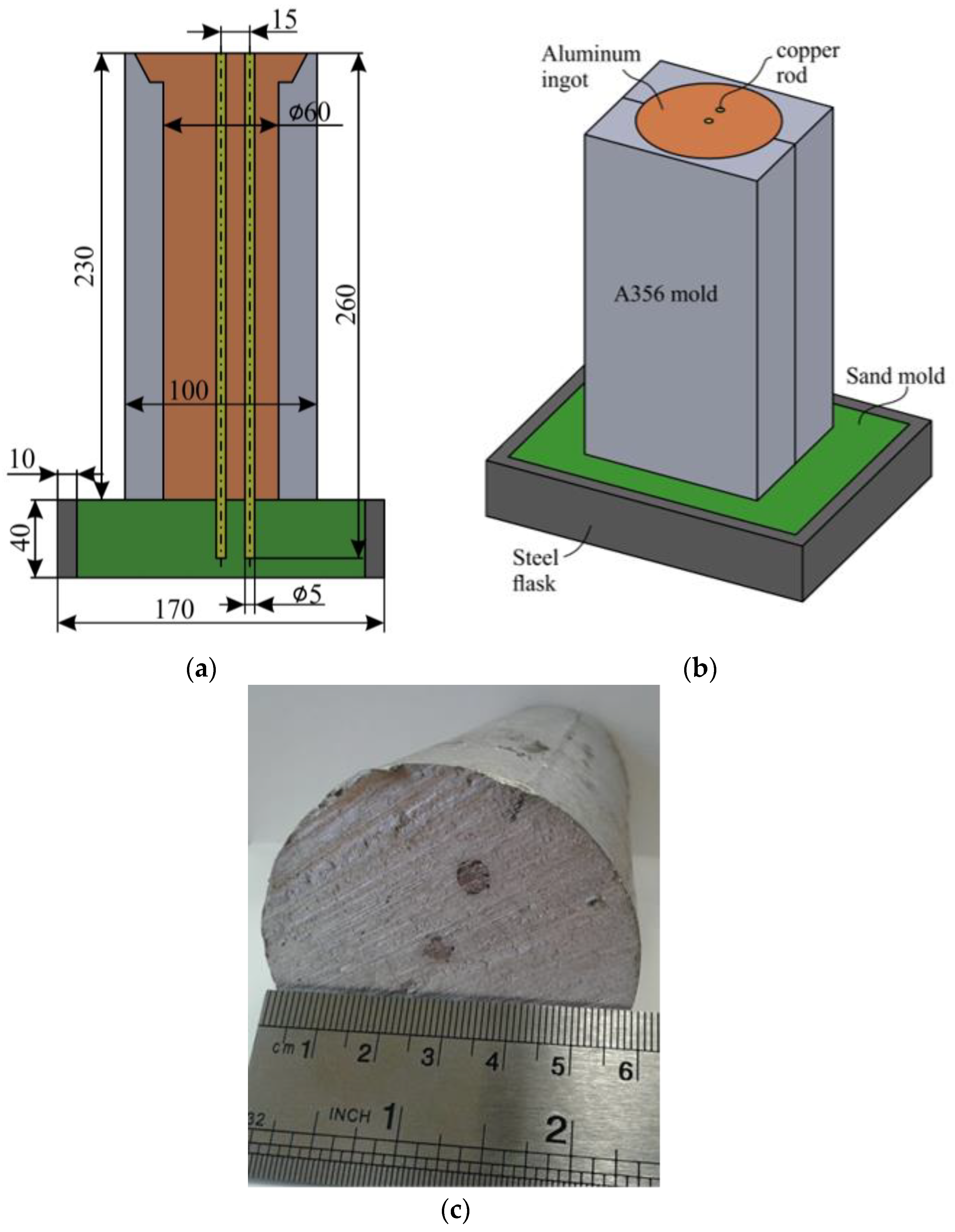
2.1. Method of Fabricating Cast Billet with Inserts

Extruded copper rods (99.7 wt.% purity) with 5 mm diameter and 200 mm length were covered by aluminum (99.85 wt.% purity). The cladding procedure consisted of melting the Al in a long and thin steel crucible and melting the flux on the Al melt surface with the following composition: 43% KCl, 37% LiCl, 10% NaCl, 10% NaF (wt.%) [28]. Due to its low weight and low melting point, the melted flux was on the top of the crucible, forming a layer of 10–20 mm thickness. The copper rods were immersed in flux and in melt. After that, the Al clad was formed on the copper rod.
The copper rods were forced into a bed of furan-based, resin-bonded sand following the scheme presented on Figure 1. Then, a mold made of A356 aluminum alloy was placed on the sand bed. Before pouring, the mold walls were covered by a gravity dye coating of Cillolin Al285. The Al melt was prepared in a clay graphite crucible and degassed with hexachloroethane. Ingots of 60 mm diameter and 210 mm height with copper rods inside were fabricated.

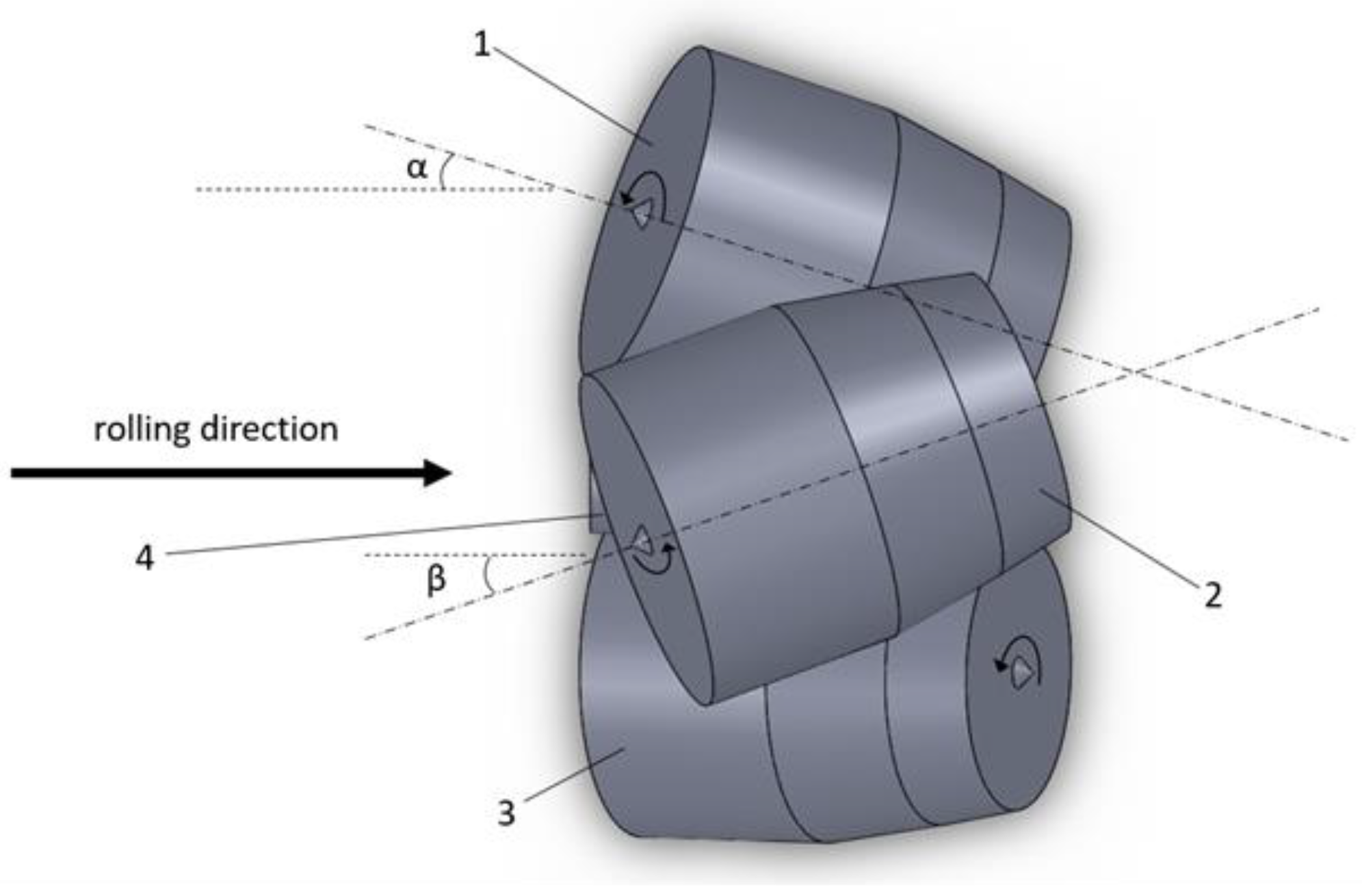
2.2. Experimental Rolling Technique

The fabricated aluminum ingots with copper inserts were rolled in an MISIS-100T three-high screw rolling mill. The ingots were preliminarily heated till 400 °C and kept in the furnace for 3 h. Screw rolling was performed at 12- and 20-degrees feed angles of rolls; the rolls inclination angle was 10 degrees for all the experimental rolling. The MISIS-100T screw rolling scheme is presented in Figure 2. One ingot was not rolled but was heated with the ingots rolled further. This unrolled ingot was taken from the furnace together with the ingots intended for rolling, which were cooled in air. All the rolled billets were also cooled in air after rolling. The billets’ diameters after rolling were 49–51 mm.
X-ray images of the ingot and billets after rolling were made using a Philin 238 (Russia) universal X-ray television complex. Several types of X-ray photographs were taken. The first type was taken with high contrast to obtain the rolled billet and original ingot contours. The second type was taken with less contrast to obtain the copper inserts contours. The X-ray images presented below in the Results and Discussion section are the superimposed images of the first and second types of the X-ray photographs.

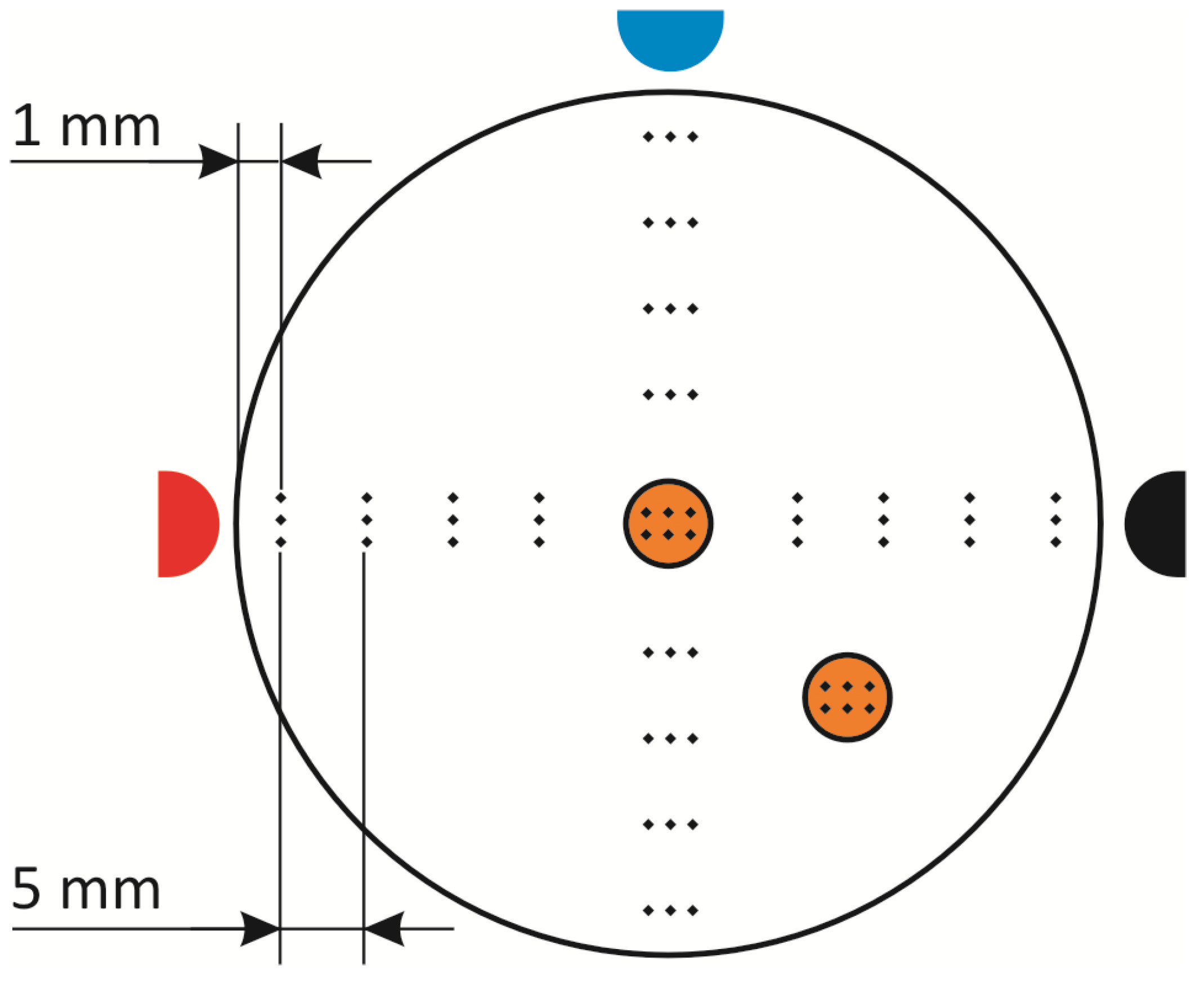
2.3. Hardness Measuring Method

Front and back edge troughs were cut from the rolled billets after the X-ray images were taken. The billets had flat edges after cutting the troughs. After that, each rolled billet was cut into 10 pieces of equal thickness (Figure 3). Each piece had three color marks (Figure 3) in order to fix the piece’s position with respect to the uncut billet: blue—vertical, red—left horizontal, black—right horizontal. These marks were used while photographing and processing the obtained photographs during the subsequent investigation.
The Vickers hardness was measured using a Micromet 5101 tester with 1 N load according to the scheme illustrated in Figure 4. The measurements were performed in cross-section along two perpendicular diameters with a 3–5 mm step and a 1 mm margin from the edge of the sample. There were three measurements at each point, and the mean value was calculated. Six measurements were taken for each of the two copper inserts cross-sections. The hardness measurement was performed for the samples 1, 2, 4, 6, 8, and 10 (Figure 3). The hardness of the ingot was measured in a similar way to the rolled billets: the aluminum hardness was measured along two perpendicular diameters, and the copper hardness was measured at 6 points for each of the inserts’ cross-sections.

2.4. Microstructure Research Method

The microstructure investigation of the billets (aluminum and copper) before and after rolling was performed in cross-section using piece 5, which approximately corresponded to the middle of the billet length. The aluminum microstructure research was performed by photographing the section surface at low magnification after 25% CuCl2 water solution etching followed by lightening with concentrated HNO3. The copper microstructure was investigated using an NIM-100 optical microscope at ×100 and ×500 magnification after 50% HNO3 water solution etching. For the microstructure and EDS analysis of the interface between the aluminum billet and the copper insert, a Tescan Vega SBH3 scanning electron microscope (SEM), equipped with an EDS system (Oxford Instruments (UK)), was used.

2.5. Three-Dimensional Rolled Billets Model Creation Method

Each of the samples (Figure 3) was measured; the copper inserts’ cross-sections were measured, and their location with respect to vertical and horizontal was determined. SolidWorks software (Education 1000 CAMPUS) was used to create the samples’ contours considering the samples’ thickness, the samples’ dimensions, and the location of the inserts’ cross-sections. After that, three-dimensional models of the rolled billets were created using SolidWorks software (Education 1000 CAMPUS).

3. Results and Discussion

The superimposed images of the ingot and the rolled billets based on X-ray photographs are presented on Figure 5. Several breaks in the copper inserts can be seen in Figure 5. There were three breaks in the central copper insert and one break in the insert located at the half-radius of the billet after rolling with a 12-degrees rolls feed angle. There were four breaks in the central copper insert and three breaks in the insert located at the half-radius of the billet after rolling with a 20-degrees rolls feed angle. Considering the larger number of breaks in the inserts after 20-degrees rolls feed angle rolling, it is possible to assume that the tensile stress experienced by the inserts was higher at a 20-degrees rolls feed angle compared to a 12-degrees rolls feed angle. It can be seen from Figure 5 that the insert located at the half-radius of the billet was more twisted after 20-degrees rolls feed angle rolling compared to after 12-degrees rolls feed angle rolling.
The hardness variation along the ingot’s radius is presented in Figure 6. The hardness was higher in the center and it decreased when approaching the ingot surface. The range of values was 29–38 HV, with a mean value of 32.5 HV.
The copper insert in the ingot center exhibited a 65–70 HV hardness range, with a 65.7 HV mean value. The copper insert in the ingot located at the half-radius of the billet exhibited a 63–71 HV hardness range, with a 67.3 HV mean value.
The aluminum hardness variation along the rolled billet radius for each of the examined pieces is presented on Figure 7.
Apart from piece 10 (Figure 7f), at a 12-degrees feed angle (the trend line changes little; hence, it is the same for the hardness change), there was a general trend observed for all the other pieces after 12-degrees feed angle rolling. This trend showed a decrease in hardness from the billet center till some minimum located at a 0.5–0.8 billet radius, and then there was a slight increase in the hardness values. The same trend was observed for aluminum alloy bar three-high screw rolling at a 20-degrees feed angle [18], for austenitic stainless-steel three-high screw rolling at an 18-degrees rolls feed angle [29], and for titanium alloy billet three-high screw rolling at a 20-degrees rolls feed angle [30]. Hence, the three-high RSR was applied in [18,29,30]. The data in Figure 7 showing the observed trend was obtained for the screw rolling at a 12-degrees feed angle, which was not RSR (the rolls feed angle was less than 18 degrees).
The trend in the change in hardness described in the previous paragraph was observed for pieces 6, 8, and 10 after rolling at a 20-degrees feed angle (Figure 7d–f), that is, RSR. For the remaining pieces—1, 2, and 4—another trend was observed after rolling at a 20-degrees feed angle. This trend was a monotonous increase in hardness from the center of the rolled billet towards its surface. The same trend was observed for tube steel three-high rolling at a 20-degrees rolls feed angle [31], nickel alloy at an 18-degrees rolls feed angle [32], and magnesium alloy at an 18-degrees rolls feed angle [33]. That is, all these investigations were conducted under conditions of the three-high RSR [31,32,33].
It is known that the hardness of fairly ductile materials correlates with strength, particularly with the ultimate tensile strength [34,35]. It is, therefore, reasonable to assume that there is a trend almost entirely to ring-shaped fracture for 12-degrees roll feed angle rolling. There is a trend to both ring-shaped and central (axial) fracture when rolling at a 20-degrees rolls feed angle. It is worth mentioning that the author of [36] notes (based on data for experimental rolling) that both central and ring-shaped fracture occurs at three-high rolling.
The mean value of the aluminum hardness for pieces was calculated and a diagram illustrating the mean value depending on the number of the piece and the rolls feed angle was plotted (Figure 8).
According to Figure 8, the mean value of the aluminum hardness after 12-degrees feed angle screw rolling was within 33.8–35.1 HV, and after 20-degrees feed angle screw rolling, it was within 33.9–37.1 HV. Hence, rolling at a 12-degrees feed angle screw resulted in an 8% increase in the mean hardness value, while, when rolling at 20 degrees, there was a 14% increase.
Figure 9 shows the copper hardness variation for the central insert and for the insert located at the half-radius of the billet after rolling at 12- and 20-degrees feed angles.
The central copper insert had hardness within 71–91 HV after rolling with a 12-degrees feed angle and 84–90 HV after rolling with a 20-degrees feed angle. The copper insert located at the half-radius of the billet after rolling at a 12-degrees feed angle had 63–85 HV hardness, and 73–90 HV at a 20-degrees feed angle.
Comparing the ingot hardness and the rolled billets hardness, the following should be noted: There was no sufficient increase in the mean hardness of aluminum—the highest increase (10%) was found only for one piece after 20-degrees feed angle rolling. The central copper insert demonstrated a 40% increase in hardness after 12-degrees feed angle rolling and up to 37% after 20-degrees feed angle rolling. The copper insert located at the half-radius of the billet showed a 26% increase in hardness after 12-degrees feed angle rolling and 34% after 20-degrees feed angle rolling. Hence, it can be assumed that 12-degrees feed angle rolling increases the billet central area hardness more compared to 20-degrees feed angle rolling. Rolling at a 20-degrees feed angle increases the hardness of the area located near to the half-radius of the billet compared to 12-degrees feed angle rolling.
The billet’s microstructure before and after screw rolling was investigated. The original aluminum ingot was characterized by a coarse-grain, as-cast structure with 300–1500 μm grain size (Figure 10a). Grains elongated along the billet radius and slightly twisted in one direction after rolling (Figure 10b,c). Apart from that, there was an inflection of grains along the ingot circumference which was the reverse of the twist direction. This inflection was 2 mm from the ingot surface and was found after 12-degrees feed angle rolling. A similar microstructure was observed for the billet after 20-degrees feed angle rolling, but this structure was more complex and non-uniform.
The copper inserts in the original ingot showed a non-uniform microstructure (Figure 11); the peripheral area had a coarse-crystalline overheated structure, which was the result of interaction of the copper insert surface with the aluminum melt, whereas the central area of the insert was more fine-grained. The copper insert microstructure did not change sufficiently after screw rolling (Figure 12).
SEM images of the interface microstructure between the copper insert and the aluminum are presented on Figure 13. The diffusion layer surrounding the copper was relatively thin—approximately 20 μm thickness. Most likely, this layer was the Al5Cu8 intermetallic phase. This layer was formed due to diffusion between the liquid Al and the solid Cu. Next to this layer, there was a 200–500 μm thickness layer, which was Al–Cu melt close to the [Al + Al2Cu] eutectic composition. When moving further from the copper insert, there was Al–Cu alloy with α-Al dendrites (dark dendrite crystals) and [Al + Al2Cu] eutectic (light irregular inter-dendritic) precipitates.
When analyzing the microstructure and hardness, it is worth noting that they depend significantly on the temperature as well as the stress–strain condition. Hence, there could be an overlap of temperature and stress-strain influences and this is an issue to be investigated in further research. Nevertheless, the hardness change patterns observed as a result of the present research have been identified for other screw rolling temperature and deformation regimes and for other materials, such as titanium alloy [30], steels [29,31], nickel alloy [32] and magnesium alloy [33]. Microstructure twist, as illustrated in Figure 10b,c, was identified for the three-high screw rolling of commercial pure aluminum billet at completely different temperatures from the current study temperature and deformation regimes [36], three-high screw rolling of AISI 1020 steel billet [37], and of AISI 321 steel billet [36]. These data indicate that stress–strain influences the microstructure and hardness formation substantially (independently form the regimes and rolled billet material), and its effect should be one of the key issues for examination in future research into screw rolling and RSR processes.
The three-dimensional models of the rolled billets were created using SolidWorks and the experimental results (Figure 14a,b). The twist angle was estimated for the insert located at the half-radius of the billet, the red one in Figure 14, and, with respect to the insert in the center of the billet, the green one in Figure 14 (Figure 14c,d). This angle was 65 degrees after 12-degrees feed angle rolling and 110 degrees after 20-degrees feed angle rolling. These values can also be estimated using the location of the copper insert cross-sections in pieces 1 and 10 as shown in Figure 5.
The results presented on Figure 14 clearly confirm the data in Figure 3 and Figure 5 concerning larger twisting of the copper insert at a 20-degrees feed angle. These results also provide a quantitative estimation: the insert twist angle after rolling at a 20-degrees rolls feed angle was 1.7 times greater compared to the same after rolling at a 12-degrees feed angle. A higher twist angle at rolling at a 20-degrees feed angle could be the reason for the higher number of copper insert breaks (compared to the number of breaks at 12-degrees feed angle rolling).
It was shown in [6,12,30] that the accumulated strain at three high screw rolling follows the same pattern (independently from the rolling regimes and the billet material): a monotonous increase from the billet center towards the billet surface. Considering the theoretical background to the strain condition when three-high screw rolling and three-high RSR [4,5], it appears that an increase in the rolls feed angle should increase the accumulated strain values in the central region of the billet or decrease the drop in the accumulated strain values between the billet surface and the billet center, as suggested in [1,4]. The authors of [4,5] noted that RSR (compared to traditional screw rolling) allows deeper deformation penetration into the billet, leading to more intense deformation of the metal throughout the billet volume. The authors of [1,5] clearly demonstrated deeper penetration of deformation for RSR compared to screw rolling, using the example of increasing the thickness of the coarse-grain layer towards the center of the billet. Hence, such microstructural change through the billet cross-section indicates an increase in the hardness of the billet cross-section after RSR compared to traditional screw rolling. There was no sufficient increase in the hardness after rolling at a 20-degrees feed angle (corresponding to RSR) observed for both aluminum and copper in terms of the conducted experiments (Figure 7, Figure 8 and Figure 9). Differences between RSR and traditional screw rolling, as a result of the investigations conducted, were found due to forming of the copper inserts. The rolling at a 20-degrees feed angle compared to the rolling at a 12-degrees feed angle increased the deformation load on the central area of the billet as well as the area located near the half-radius of the billet. This increase in deformation load was expressed in a higher number of breaks in both copper inserts. To sum up, no increase in properties was found along the billet radius with increase in the rolls feed angle value on the basis of the experiments conducted, but an influence of a rolls feed angle increase was found along the rolling direction.

4. Conclusions

Hot three-high screw rolling of an aluminum alloy ingot with longitudinal copper inserts was performed at 12- and 20-degrees rolls feed angles. The results of the conducted research have established the following:
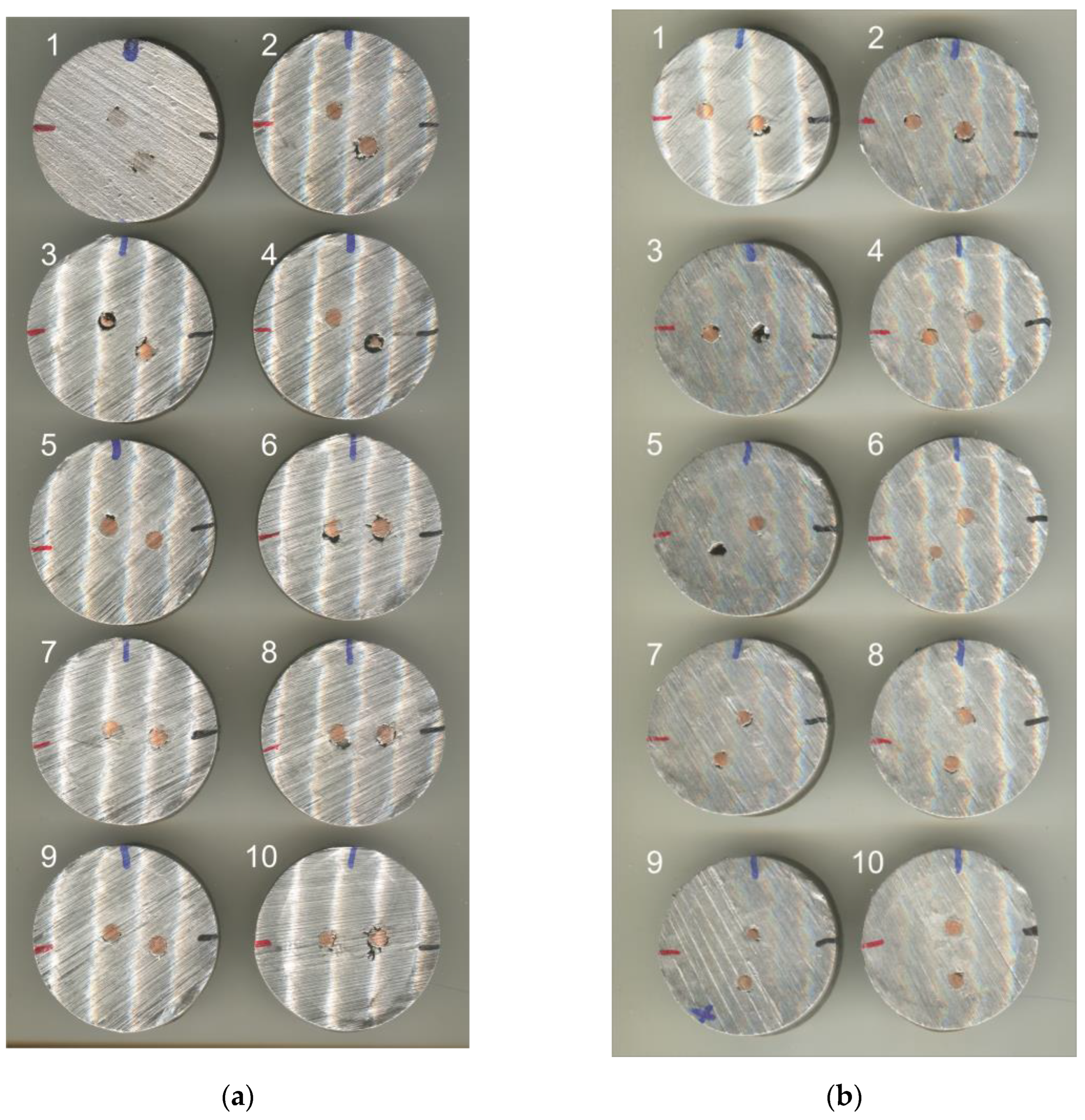
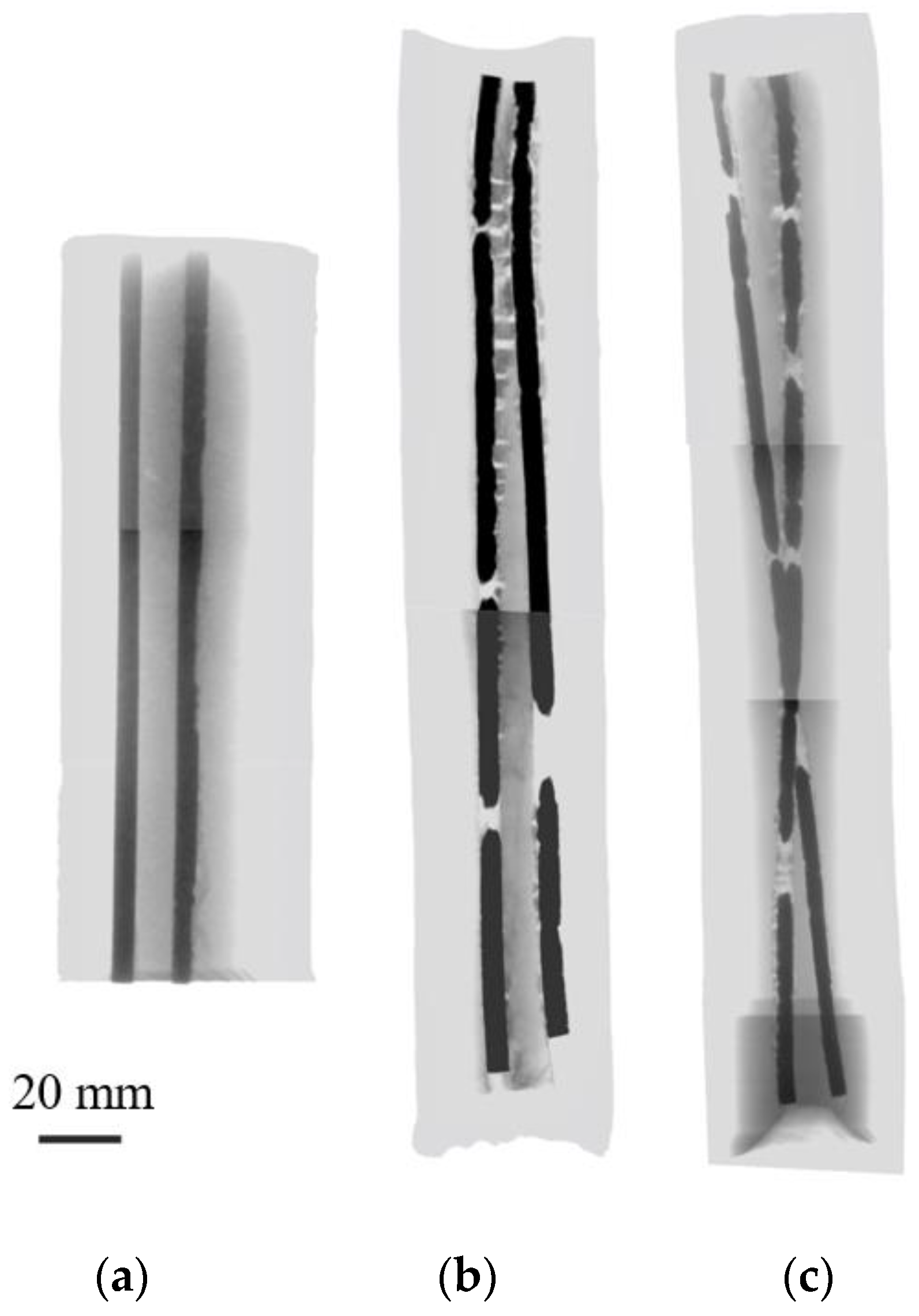
  • The copper insert twist angle with respect to the central copper insert was 65 degrees after rolling with a 12-degrees feed angle and 110 degrees after rolling with a 20-degrees feed angle. This illustrates the fact that the helical character of material flow was more clearly expressed at larger rolls feed angles. However, increasing the rolls feed angle led to an increase in the deformation load on the inserts, which, in turn, led to a higher number of breaks in them: four in the center and three at the half-radius at a 20-degrees angle compared to three in the center and one at the half-radius at a 12-degrees angle.
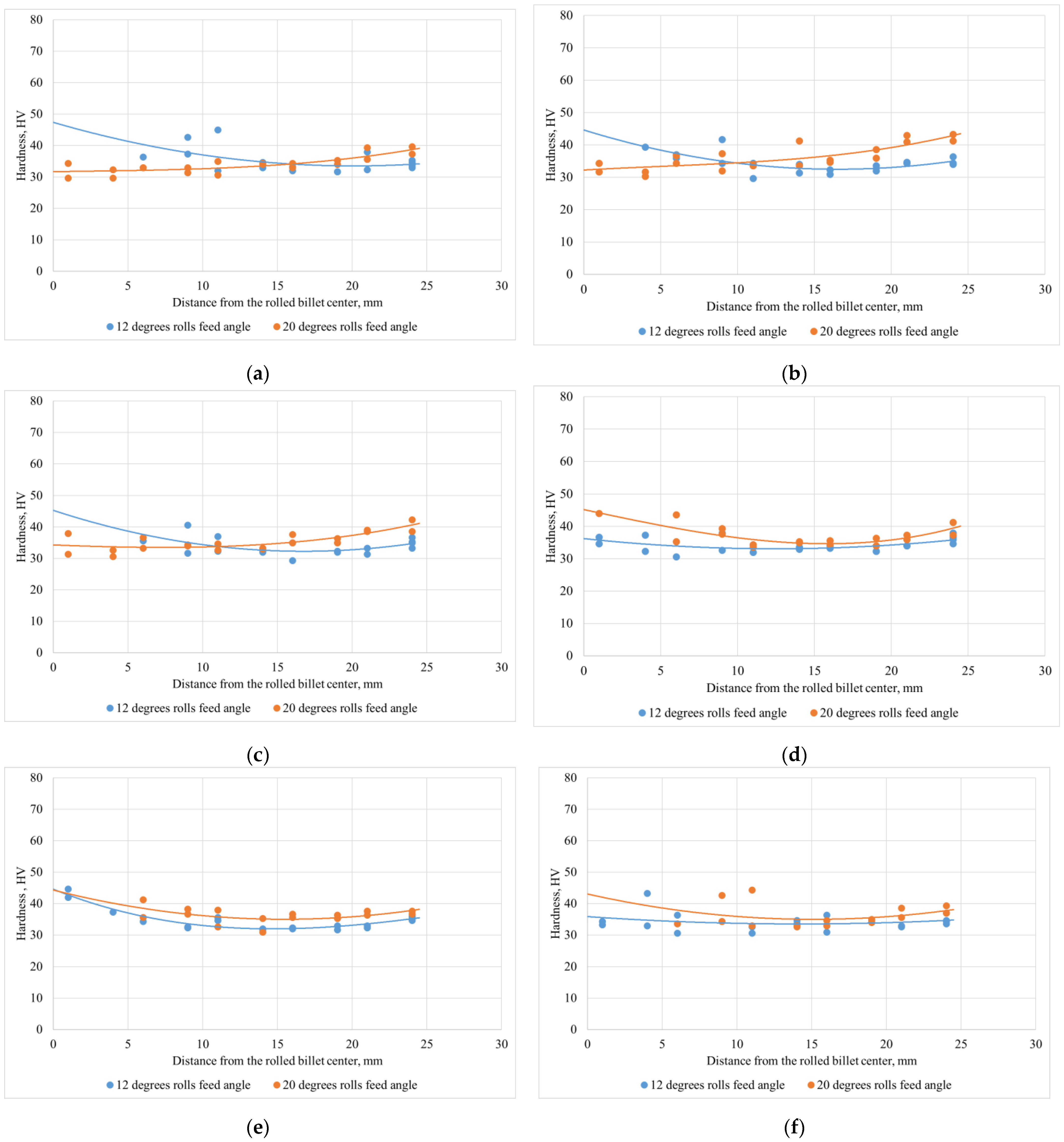
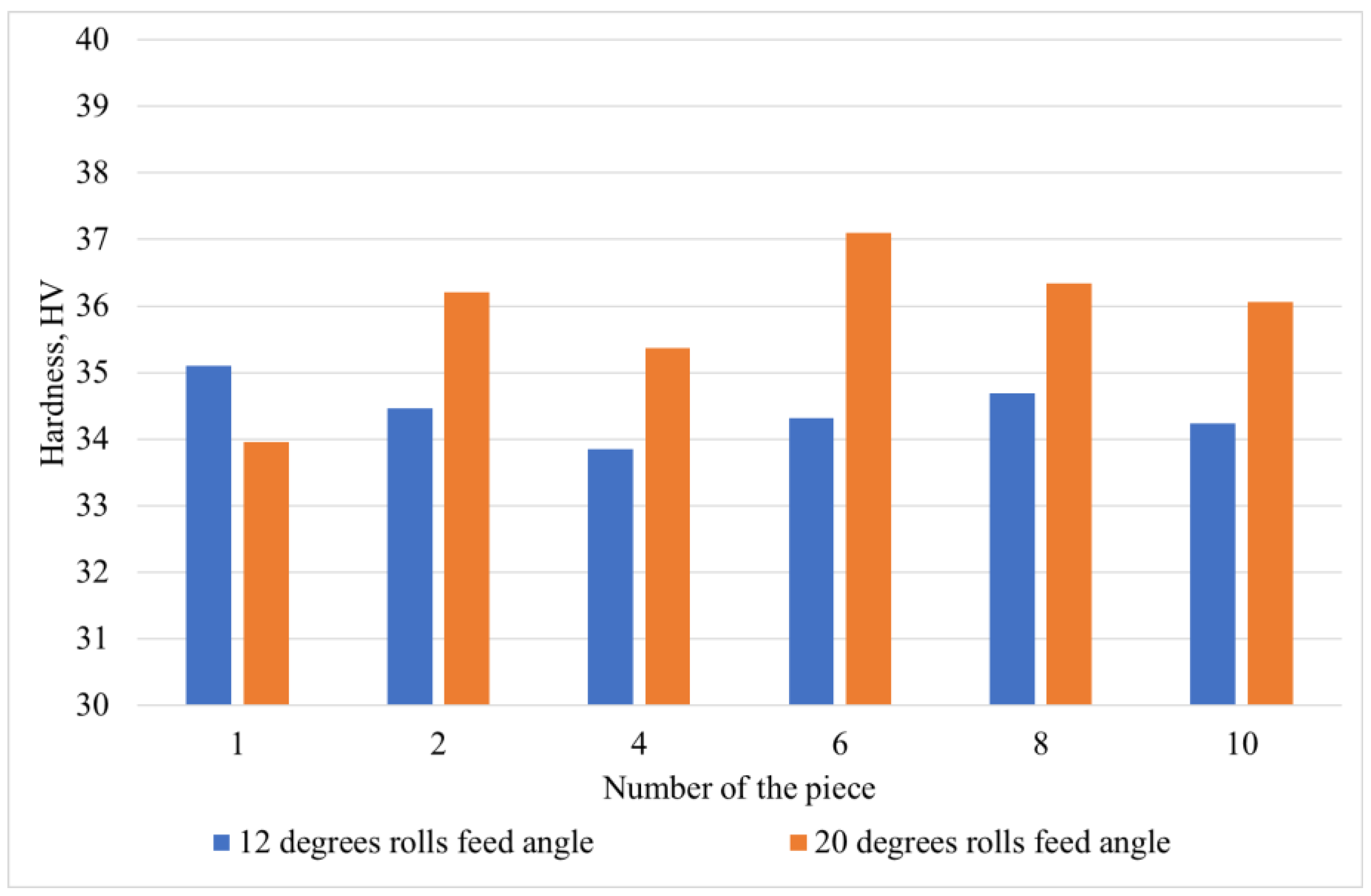
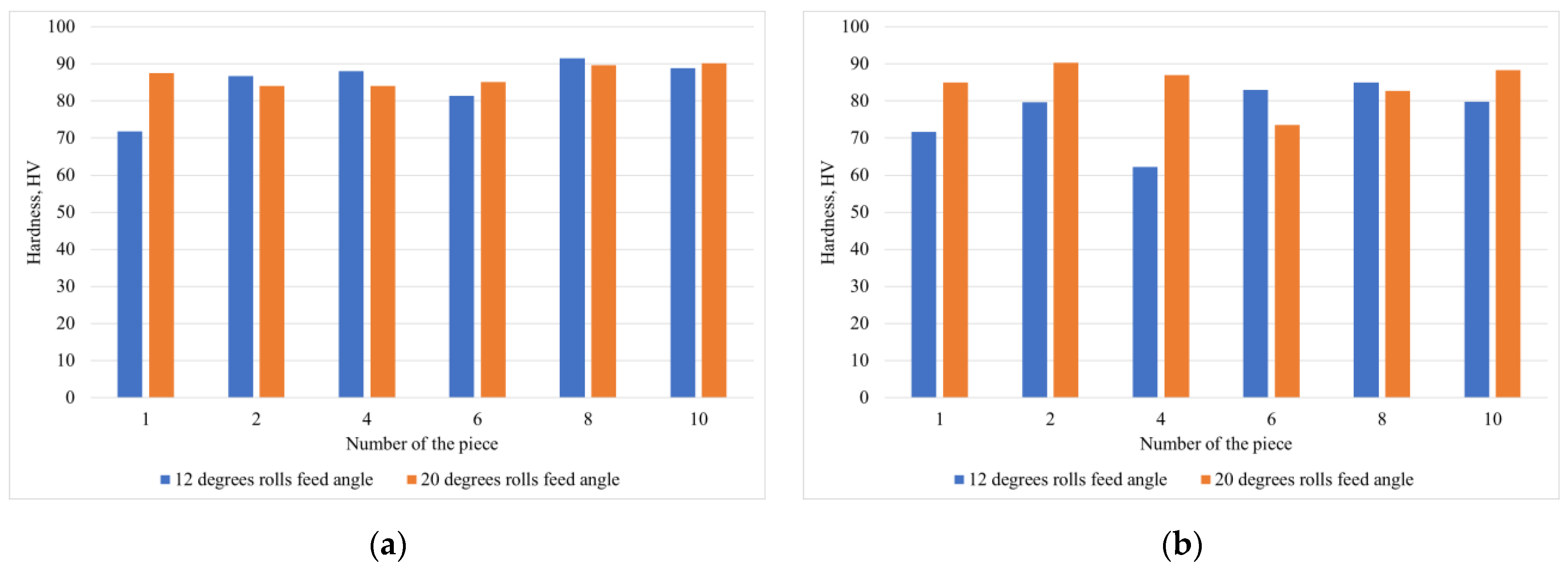
  • The increase in hardness of aluminum compared to the original ingot was 8% after rolling at a 12-degrees feed angle and 14% after rolling at a 20-degrees feed angle. There were two patterns of the hardness changing, including: (1) a decrease from the center of the billet till some minimum located at 0.5–0.8 of the billet radius, followed by a monotonous increase till the billet surface; (2) a monotonic increase from the center towards the billet surface. Type one was observed at 12-degrees feed angle rolling and both types were observed at 20-degrees feed angle rolling. The copper insert’s hardness before rolling was 65–71 HV. The central copper insert hardness was 71–91 HV after rolling at a 12-degrees feed angle and 84–90 HV after rolling at a 20-degrees feed angle. The hardness of the copper insert located at the half-radius of the billet was 63–85 after 12-degrees feed angle rolling and 73–90 after 20-degrees feed angle rolling.
  • The microstructure of the copper inserts did not change sufficiently after rolling at both feed angles. The aluminum before rolling had a coarse-crystalline, as-cast microstructure, and the grain size was 300–1500 μm. Grains elongated along the billet radius and twisted in one direction after rolling. Considering the results of earlier research, this phenomenon seems to be typical for three-high screw rolling and does not depend either on the forming and temperature regimes or on the billet material.

Author Contributions

Conceptualization, M.M.S. and B.A.R.; methodology, S.O.R., V.E.B., A.Y.T. and M.N.S.; software, M.M.S., S.O.R. and V.E.B.; validation, M.N.S., B.V.K. and S.O.R.; formal analysis, V.E.B., M.N.S. and A.V.D.; investigation, S.O.R., V.E.B., B.V.K., A.Y.T. and A.V.K.; resources, B.V.K., M.N.S. and V.E.B.; data curation, S.O.R., V.E.B. and A.V.D.; writing—original draft preparation, M.M.S., M.N.S., S.O.R. and V.E.B.; writing—review and editing, A.Y.T., A.V.K., A.V.D., B.A.R., V.E.B. and S.O.R.; visualization, M.M.S., M.N.S., S.O.R., V.E.B. and A.V.K.; supervision, M.N.S.; project administration, M.M.S., S.O.R. and V.E.B. All authors have read and agreed to the published version of the manuscript.

Funding

This research received no external funding.

Data Availability Statement

Not applicable.

Conflicts of Interest

The authors declare no conflict of interest.

References

  1. Romantsev, B.A.; Goncharuk, A.V.; Vavilkin, N.M.; Samusev, S.V. Pipe Manufacture; Izdatelskiy Dom MISiS: Moscow, Russia, 2011; ISBN 978-5-87623-504-6. (In Russian) [Google Scholar]
  2. Teterin, P.K. Theory of Cross and Screw Rolling; Metallurgija: Moscow, Russia, 1971; 368p. (In Russian) [Google Scholar]
  3. Chen, C.; Chen, J.; Shuang, Y.; Li, C. Short-flow rolling process and heat treatment of seamless titanium alloy tube. Metals 2023, 13, 527. [Google Scholar] [CrossRef]
  4. Potapov, I.N.; Polukhin, P.I. Screw Rolling Technology; Metallurgia: Moscow, Russia, 1990; 344p. (In Russian) [Google Scholar]
  5. Galkin, S.P. Theory and Technology of Steady-State Workpiece and Bar Rolling of Low-Ductility Steels and Alloys; Moscow State Institute of Steel and Alloys: Moscow, Russia, 1998. (In Russian) [Google Scholar]
  6. Skripalenko, M.M.; Karpov, B.V.; Rogachev, S.O.; Kaputkina, L.M.; Romantsev, B.A.; Skripalenko, M.N.; Huy, T.B.; Fadeev, V.A.; Danilin, A.V.; Gladkov, Y.A. Simulation of the kinematic condition of radial shear rolling and estimation of its influence on a titanium billet microstructure. Materials 2022, 15, 7980. [Google Scholar] [CrossRef] [PubMed]
  7. Kolobov, Y.R.; Golosova, O.A.; Manokhin, S.S. Regularities of Formation and Degradation of the Microstructure and Properties of New Ultrafine-Grained Low-Modulus Ti–Nb–Mo–Zr Alloys. Russ. J. Non-Ferr. Met. 2017, 59, 393–402. [Google Scholar] [CrossRef]
  8. Naydenkin, E.V.; Mishin, I.P.; Ratochka, I.V.; Lykova, O.N.; Zabudchenko, O.V. The effect of alpha-case formation on plastic deformation and fracture of near β titanium alloy. Mater. Sci. Eng. A 2020, 769, 138495. [Google Scholar] [CrossRef]
  9. Ratochka, I.V.; Mishin, I.P.; Lykova, O.N.; Naydenkin, E.V.; Varlamova, N.V. Structural Evolution and Mechanical Properties of a VT22 Titanium Alloy Under High-Temperature Deformation. Russ. Phys. J. 2016, 59, 397–402. [Google Scholar] [CrossRef]
  10. Ding, X.; Sun, L.; Huang, X.; Zhao, Z. Research on Three-Roll Screw Rolling Process for Ti6Al4V Titanium Alloy Bar. High Temp. Mater. Process. 2018, 38, 178–182. [Google Scholar] [CrossRef]
  11. Gamin, Y.V.; Muñoz Bolaños, J.A.; Aleschenko, A.S.; Komissarov, A.A.; Bunits, N.S.; Nikolaev, D.A.; Fomin, A.V.; Cheverikin, V.V. Influence of the radial-shear rolling (RSR) process on the microstructure, electrical conductivity and mechanical properties of a Cu–Ni–Cr–Si alloy. Mater. Sci. Eng. A 2021, 822, 141676. [Google Scholar] [CrossRef]
  12. Dobatkin, S.; Galkin, S.; Estrin, Y.; Serebryany, V.; Diez, M.; Martynenko, N.; Lukyanova, E.; Perezhogin, V. Grain refinement, texture, and mechanical properties of a magnesium alloy after radial-shear rolling. J. Alloys Compd. 2019, 774, 969–979. [Google Scholar] [CrossRef]
  13. Stefanik, A.; Szota, P.; Mróz, S.; Bajor, T.; Dyja, H. Properties of the AZ31 Magnesium Alloy Round Bars Obtained in Different Rolling Processes/Własności Prętów Okrągłych Ze Stopu Magnezu AZ31 Otrzymanych WRóznych Procesach Walcowania. Arch. Metall. Mater. 2015, 60, 3001–3006. [Google Scholar] [CrossRef]
  14. Stefanik, A.; Szota, P.; Mróz, S. Analysis of the Effect of Rolling Speed on the Capability to Produce Bimodal-Structure AZ31 Alloy Bars in the Three-High Skew Rolling Mill. Arch. Metall. Mater. 2020, 65, 329–335. [Google Scholar]
  15. Wang, L.; Zhang, Z.; Zhang, H.; Wang, H.; Shin, K. The dynamic recrystallization and mechanical property responses during hot screw rolling on pre-aged ZM61 magnesium alloys. Mater. Sci. Eng. A 2020, 798, 140126. [Google Scholar] [CrossRef]
  16. Patrin, P.V.; Karpov, B.V.; Aleshchenko, A.S.; Galkin, S.P. Capability Process Assessment of Radial-Displacement Rolling of Heat-Resistant Alloy HN73MBTYU. Steel Transl. 2020, 50, 42–45. [Google Scholar] [CrossRef]
  17. Arbuz, A.; Kawalek, A.; Ozhmegov, K.; Daniyeva, N.; Panin, E. Obtaining of UFG Structure of Zr-1% Nb Alloy by Radial-Shear Rolling. In Proceedings of the 29th International Conference on Metallurgy and Materials, Brno, Czech Republic, 20–22 May 2020; pp. 333–338. [Google Scholar]
  18. Gamin, Y.V.; Akopyan, T.K.; Koshmin, A.N.; Dolbachev, A.P.; Goncharuk, A.V. Microstructure evolution and property analysis of commercial pure Al alloy processed by radial-shear rolling. Arch. Civ. Mech. Eng. 2020, 20, 143. [Google Scholar] [CrossRef]
  19. Akopyan, T.K.; Belov, N.A.; Aleshchenko, A.S.; Galkin, S.P.; Gamin, Y.V.; Gorshenkov, M.V.; Cheverikin, V.V.; Shurkin, P.K. Formation of the gradient microstructure of a new Al alloy based on the Al-Zn-Mg-Fe-Ni system processed by radial-shear rolling. Mater. Sci. Eng. A 2019, 746, 134–144. [Google Scholar] [CrossRef]
  20. Derevyagina, L.S.; Gordienko, A.I.; Pochivalov, Y.I.; Smirnova, A.S. Modification of the Structure of Low-Carbon Pipe Steel by Helical Rolling, and the Increase in Its Strength and Cold Resistance. Phys. Met. Metallogr. 2018, 119, 83–91. [Google Scholar] [CrossRef]
  21. Panin, S.; Vlasov, I.; Maksimov, P.; Moiseenko, D.; Maruschak, P.; Yakovlev, A.; Schmauder, S.; Berto, F. Increasing Fatigue Life of 09Mn2Si Steel by Helical Rolling: Theoretical–Experimental Study on Governing Role of Grain Boundaries. Materials 2020, 13, 4531. [Google Scholar] [CrossRef]
  22. Panin, S.; Vlasov, I.; Moiseenko, D.; Maksimov, P.; Maruschak, P.; Yakovlev, A.; Gomorova, J.; Mishin, I.; Schmauder, S. Increasing Low-Temperature Toughness of 09Mn2Si Steel through Lamellar Structuring by Helical Rolling. Metals 2021, 11, 352. [Google Scholar] [CrossRef]
  23. Bogatov, A.A.; Panov, E.I. Effect of Stress-strain State during Helical Rolling on Metal and Alloy Structure and Ductility. Metallurgist 2013, 57, 434–441. [Google Scholar] [CrossRef]
  24. Lezhnev, S.N.; Naizabekov, A.B.; Volokitina, I.E.; Panin, E.A.; Kuis, D.V. Recycling of stainless steel bar scrap by radial-shear rolling to obtain an ultrafine-grained gradient structure. Litiyo Metall. (Foundry Prod. Metall.) 2021, 2, 61–67. [Google Scholar] [CrossRef]
  25. Zhuchin, V.N.; Potapov, I.N.; Aleksandrovich, A.I.; Akhmedshin, R.I.; Kharitonov, E.A.; Dereviashkin, V.P.; Zimin, V.Y. Moscow Steel and Alloys Institute (Elektrostal Branch), Assignee. Sample for the Research of Stress-Strain State. Soviet Union Patent SU 946707, 4 February 1981. [Google Scholar]
  26. Vorontsov, V.K.; Polukhin, P.I.; Belevitin, V.A.; Brinza, V.V. Experimental Methods of Mechanics of Deformable Solids (Technological Challenges of Metal Forming); Metallurgia: Moscow, Russia, 1990; 480p, ISBN 5-229-00175-5. (In Russian) [Google Scholar]
  27. Belevitin, V.A. Design and Improvement of Methods of Experimental Mechanics for Metal Forming Technological Processes Optimization; Ufalei Metallurgical Engineering Plant: Verkhniy Ufalei City, Russia, 1997. (In Russian) [Google Scholar]
  28. Watanabe, T.; Komatu, S.; Yanagisawa, A.; Konuma, S. Development of flux and filler metal for brazing magnesium alloy AZ31B. Yosetsu Gakkai Ronbunshu/Q. J. JPN Weld. 2004, 22, 163–167. [Google Scholar]
  29. Skripalenko, M.M.; Romantsev, B.A.; Kaputkina, L.M.; Galkin, S.P.; Skripalenko, M.N.; Cheverikin, V.V. Study of transient and steady-state stages during two-high and three-high screw rolling of a 12kh18n10t steel workpiece. Metallurgist 2019, 63, 366–375. [Google Scholar] [CrossRef]
  30. Skripalenko, M.M.; Galkin, S.P.; Karpov, B.V.; Romantsev, B.A.; Kaputkina, L.M.; Danilin, A.V.; Skripalenko, M.N.; Patrin, P.V. Forming features and properties of titanium alloy billets after radial-shear rolling. Materials 2019, 12, 3179. [Google Scholar] [CrossRef] [PubMed]
  31. Surikova, N.S.; Vlasov, I.V.; Derevyagina, L.S.; Gordienko, A.I.; Narkevich, N.A. Influence of cross-screw rolling modes on mechanical properties and fracture toughness of Pipe Steel. Izv. Ferr. Metall. 2021, 64, 28–37. [Google Scholar] [CrossRef]
  32. Bikmukhametova, A.; Galieva, E.; Valeev, I.; Klassman, E.; Musabirov, I.; Valitov, V. The influence of radial shear rolling on the structure and properties of 58ni-cr-Mo-B-al-Cu Superalloy. Lett. Mater. 2021, 11, 566–570. [Google Scholar] [CrossRef]
  33. Stefanik, A.; Szota, P.; Mróz, S.; Wachowski, M. Changes in the properties in bimodal Mg alloy bars obtained for various deformation patterns in the RSR rolling process. Materials 2022, 15, 954. [Google Scholar] [CrossRef]
  34. Shaposhnikov, M.A. Mechanical Testing of Metals; Gosudarstvennoe Nauchno-Tehnicheskoe Mashinostroitelnoy Literature: Moscow-Leningrad, Russia, 1951; p. 385. (In Russian) [Google Scholar]
  35. McLean, D. Mechanical Properties of Metals, 1st ed.; Wiley: New York, NY, USA, 1962; p. 407. [Google Scholar]
  36. Nikulin, A.N. Screw Rolling. Stresses and Strains; Metallurgizdat: Moscow, Russia, 2015; ISBN 978-5-902194-82-8. (In Russian) [Google Scholar]
  37. Skripalenko, M.M.; Rogachev, S.O.; Romantsev, B.A.; Galkin, S.P.; Kaputkina, L.M.; Skripalenko, M.N.; Danilin, A.V.; Fadeev, V.A. Creation of 3D model of stainless-steel billet’s grain after three-high screw rolling. Materials 2022, 15, 995. [Google Scholar] [CrossRef]
Figure 1. Scheme of the copper inserts positioning inside the aluminum ingot (a), the assembly for casting (b), and the fabricated ingot (c).
Metals 13 01671 g001
Figure 2. Screw rolling scheme using MISIS-100T mill: 1,2,3—rolls, 4—ingot, α-rolls inclination angle, β—rolls feed angle value.
Metals 13 01671 g002
Figure 3. Pieces after cutting the billet after three-high screw rolling at 12 degrees (a) and 20 degrees (b).
Metals 13 01671 g003
Figure 4. Scheme of the hardness measurement of the pieces cross-section after three-high screw rolling.
Metals 13 01671 g004
Figure 5. Superimposed images based on X-ray photographs of the ingot (a), billet rolled at 12-degrees rolls feed angle (b), and billet rolled at 20-degrees rolls feed angle (c).
Metals 13 01671 g005
Figure 6. Aluminum hardness variation along the ingot’s radius.
Metals 13 01671 g006
Figure 7. Aluminum hardness variation along the radius of pieces 1 (a), 2 (b), 4 (c), 6 (d), 8 (e), 10 (f) after three-high screw rolling at 12- and 20-degrees rolls feed angle.
Metals 13 01671 g007
Figure 8. Mean values of the aluminum hardness for the cross-section of pieces after three-high screw rolling at 12- and 20-degrees rolls feed angles.
Metals 13 01671 g008
Figure 9. Copper hardness of the central insert (a) and the insert located at the half-radius of the billet (b) after three-high rolling at 12- and 20-degrees rolls feed angles.
Metals 13 01671 g009
Figure 10. Original ingot microstructure (a) and microstructure of the billet after 12-degrees feed angle rolling (b) and 20-degrees feed angle rolling (c).
Metals 13 01671 g010
Figure 11. Copper insert microstructure in the original ingot.
Metals 13 01671 g011
Figure 12. Microstructure of the copper insert after 12- (a,b) and 20-degrees (c,d) feed angle rolling: (a,c)—the peripheral area of the insert, (b,d)—the central area of the insert.
Metals 13 01671 g012
Figure 13. Copper/aluminum interface microstructure in the original ingot, part of interface analyzed by EDS that shown by green box, and the EDS maps showed the distribution of Al and Cu.
Metals 13 01671 g013
Figure 14. Three-dimensional models of the billets rolled at 12- (a) and 20-degrees (b) feed angle, and estimation of the copper inserts twist angles after 12- (c) and 20-degrees (d) feed angle rolling: green – central insert, red – half-radius insert.
Metals 13 01671 g014
Disclaimer/Publisher’s Note: The statements, opinions and data contained in all publications are solely those of the individual author(s) and contributor(s) and not of MDPI and/or the editor(s). MDPI and/or the editor(s) disclaim responsibility for any injury to people or property resulting from any ideas, methods, instructions or products referred to in the content.

