Article

Surface Morphology Analysis of Laser Shock Peened 20CrMnTi Steel: A Statistical Evaluation

1
School of Mechanical Engineering, Jiangsu University, Zhenjiang 212013, China
2
School of Mechanical and Precision Instrument Engineering, Xi’an University of Technology, Xi’an 710048, China
*
Author to whom correspondence should be addressed.
Metals 2023, 13(10), 1673; https://doi.org/10.3390/met13101673
Submission received: 21 August 2023 / Revised: 24 September 2023 / Accepted: 27 September 2023 / Published: 29 September 2023
(This article belongs to the Special Issue Surface Engineering and Coating Tribology)

Abstract

:
Surface morphology impacts material performance and durability significantly. To gain a deeper understanding of the impact of laser shock peening (LSP) treatment on the surface morphology of materials and to explore more optimized LSP treatment strategies, this study presents an investigation into the surface morphology of 20CrMnTi steel following LSP treatment. Through the application of statistical analysis, the study examines the induced surface morphology variations resulting from both single-point repetitive LSP and multiple LSP treatments. Experimental results demonstrate significant alterations in surface roughness and peak height distribution after LSP treatments, accompanied by the presence of high amplitude compressive residual stress (CRS). Moreover, the depth of laser-induced indentations is found to be closely related to the number of impacts, and the incidence angle of the laser exhibits a discernible influence on the directional texture and periodicity of the impacted surfaces. This investigation also proposes a method for estimating surface morphology variations after LSP treatment by means of analysis of impact patterns, thereby offering the potential for enhancing the friction and wear performance of the impacted surfaces through the adjustment of the impact region position during multi-layer LSP treatment.

1. Introduction

The 20CrMnTi steel demonstrates high hardenability and low-temperature impact toughness. Additionally, it possesses excellent fatigue resistance and wear resistance properties, rendering it a widely employed material for the fabrication of crucial industrial components [1]. Although heat treatment is commonly employed as a surface strengthening technique, its efficacy may be limited when dealing with intricate-shaped components, especially in terms of localized strengthening.
In recent years, laser shock peening (LSP) has attracted significant attention as a novel technique for surface modification of metallic materials and alloys [2,3,4] and is now widely used for fabricating advanced devices in aerospace [5], nuclear power [6], and biomedical applications [7,8]. LSP utilizes the impact wave effect generated by laser-induced plasma, thereby inducing a series of unique surface strengthening effects [9,10,11,12]. These effects include the formation of a dense and stable dislocation structure in the surface layer of the metallic materials, accompanied by pronounced surface hardening [13,14]. Additionally, it produces a deeper layer of compressive residual stress (CRS), with a depth exceeding 1 mm [13,15]. These effects significantly enhance fatigue life [5,16,17,18] and stress corrosion resistance [19,20,21], while also influencing the friction [22,23] and wear resistance [24,25,26] properties of the treated surface.
Despite the wide application of LSP, there are still challenges in fully comprehending the underlying mechanisms and achieving precise control over the LSP-induced changes in surface morphology. Nevertheless, some researchers have made progress in the study of plastic deformation [27,28,29], residual stress analysis [30,31], and microstructure observation [12,14,32,33,34,35]. However, current research on the morphology of laser-impacted surfaces often focuses on the analysis of surface roughness, while the statistical analysis of three-dimensional parameters of surface morphology and their correlation with friction and wear resistance remains insufficiently explored.
Hence, the primary objective of this study is to investigate and characterize the surface morphology of laser shock peened 20CrMnTi material. Specifically, it aims to conduct a detailed description, statistical analysis, and evaluation of the LSP-induced surface variations. Additionally, this study aims to propose a feasible approach for performing multi-layer LSP in multiple impacts to achieve a smoother surface. The outcomes of this research endeavor are expected to provide valuable insights into the surface morphology resulting from LSP and to contribute to the overall optimization of LSP processing techniques.
To achieve a more in-depth evaluation of laser shock peened surfaces, this study employs several three-dimensional surface morphology parameters to assess the quality of laser-impacted surfaces, distinguishing itself from traditional methods that mainly rely on surface roughness measurements. Furthermore, our approach integrates impact patterns into the evaluation process, offering a more efficient and easily executable method for assessing the quality of laser-impacted surfaces while reducing the need for complex post-analysis and numerical simulations.

2. Materials and Methods

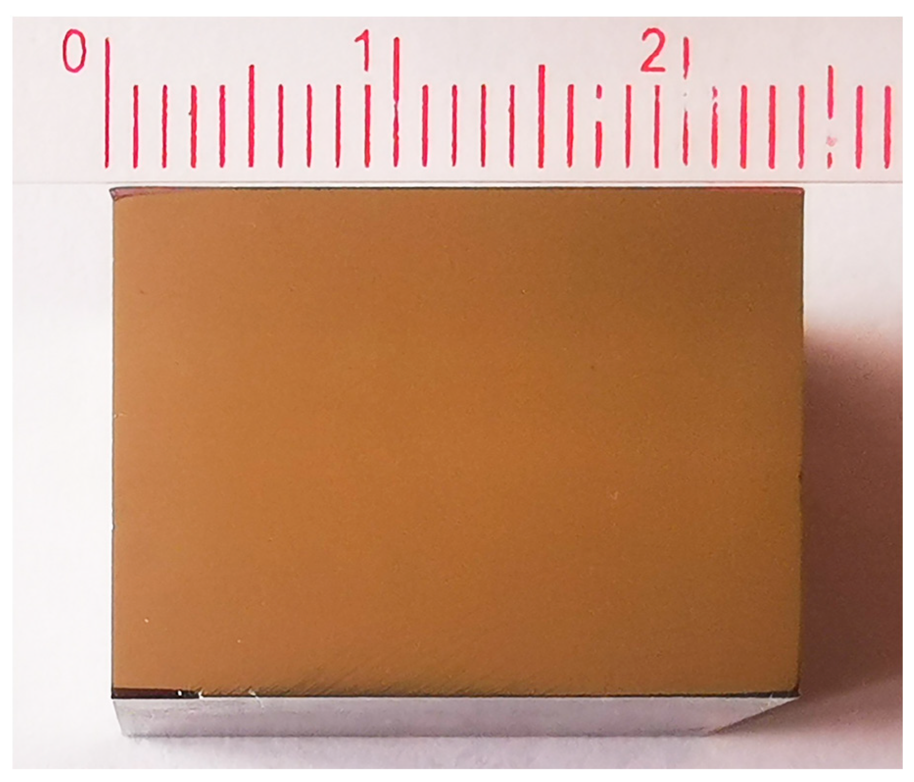
2.1. Specimen Preparation

Rectangular blocks measuring 24 mm × 18 mm × 6 mm were machined as the initial specimens from the raw material of 20CrMnTi, with the chemical composition listed in Table 1 and its physical and mechanical properties listed in Table 2. To further consolidate the structure, a cold pressing treatment was subsequently employed. The specimens were placed in a hydraulic press machine with a pressure of 250 MPa applied for 5 min. Following this, the specimens were placed into a high-temperature furnace for a 1-h solution treatment, aimed at alleviating internal stresses and enhancing the crystalline structure. Prior to specimen placement, the furnace was preheated to 850 °C and allowed to reach thermal equilibrium. After the completion of the solution treatment, the specimens were promptly withdrawn from the furnace and quenched in an oil bath at room temperature. Subsequently, an aging treatment was conducted at 140 °C for a duration of 20 h.
The upper surface of the specimens designated for treatment underwent a series of polishing steps. Initially, 150-mesh, 500-mesh, and 1200-mesh metallographic sandpapers were successively employed to eliminate surface roughness and non-uniformity. Subsequently, a W1.0 polishing agent was applied to further refine the surface. To ensure the absence of residual contaminants or polishing agents, the specimens were immersed in anhydrous ethanol and subjected to ultrasonic cleaning. Finally, a thorough drying treatment was performed. The resulting appearance of the treated specimens prior to LSP is illustrated in Figure 1.

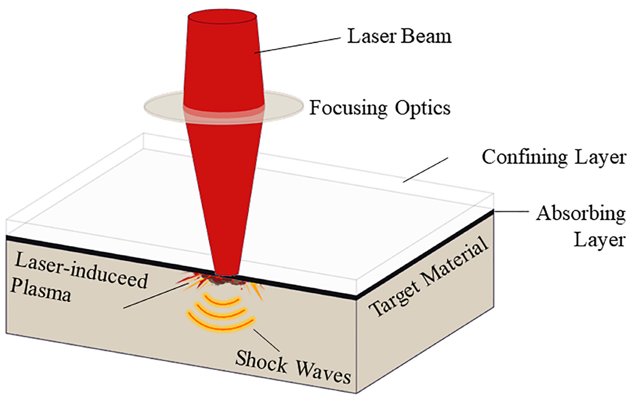
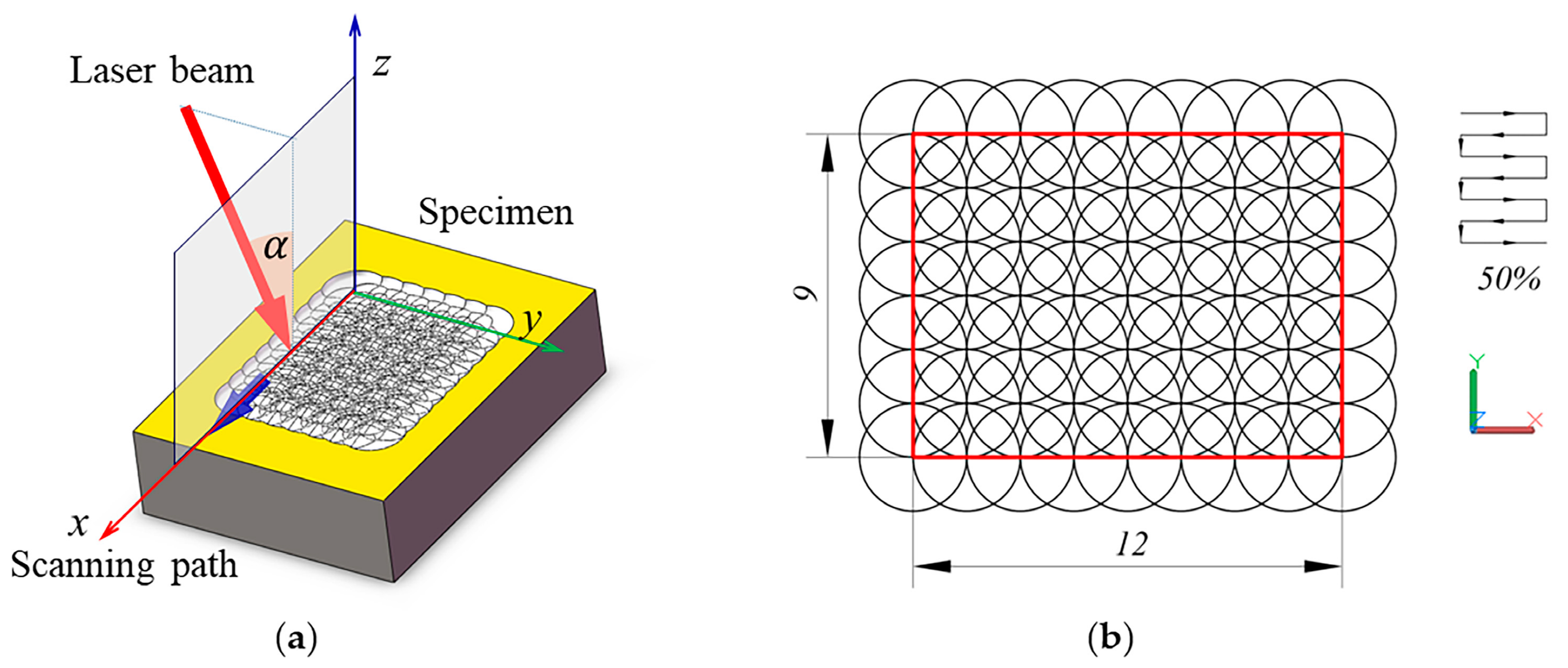
2.2. LSP Experiments

The LSP experiments were conducted within a controlled laboratory environment maintained at a constant temperature of 25 °C. The experimental schematic diagram of LSP processing is shown as Figure 2. A YAG:1064 laser, operating at a wavelength of 1064 nm and with a pulse width of 20 ns, was employed, delivering laser pulses with a pulse energy of 9J at a repetition frequency of 1 Hz. Circular spots with a 3 mm diameter were utilized, and the laser intensity distribution followed a Gaussian distribution in space. Prior to the LSP, the designated impact region of the specimens underwent preparation steps involving the application of an approximately 10 μm-thick organic adhesive layer followed by the affixation of a 100 μm-thick aluminum foil onto the surface as the absorbing layer. During laser processing, deionized water was sprayed from a nozzle to form a water film, with a thickness of approximately 1.5 mm, on the surface as the confining layer. The main parameters of laser shock processing are listed in Table 3.
Single-point repetitive impact experiments were performed by directing the laser beam perpendicular to the surface of the material. The specimen was subjected to a different number of repeated impacts at positions A, B, C, and D, as shown in Figure 3a. After the completion of the LSP treatment, both the aluminum foil and the organic adhesive layer on the specimen surface were removed or cleaned off. Afterward, residual debris present on the surface was carefully removed using ethanol. Subsequent measurements were then conducted to assess both the surface morphology and residual stresses. To ensure repeatability and enable meaningful comparative analysis, the single-point repetitive impact experiments were conducted using four specific specimens, namely S−1, S−2, S−3, and S−4, respectively. The information list of these specimens for LSP treatment is provided in Table 4.
The surface morphology of the specimens was measured using a confocal laser scanning microscope (Keyence VK-X250K, Keyence Corporation, Osaka, Japan) equipped with a 408 nm laser and a 10× objective lens. Measurements of surface morphology were performed within 5 mm × 5 mm rectangular regions, positioned at the center of the laser spots in the single-point repetitive impact experiments.
For residual stress measurements, an X-ray diffractometer (X-350A, Handan Stress Technologies Co., Ltd., Handan, China) equipped with a Cr K α radiation source was used. The sin 2 ψ method was employed to analyze the diffraction peaks and determine the residual stress values. As shown in the Figure 3b, measurements of residual stress were first taken at the points located at the center of the laser spots. Subsequently, four points situated 1 mm away from the center of the laser spot were measured, and the average value of the residual stresses at these points was taken as the representative value.
During LSP treatment, the laser-induced shock waves can cause severe plastic deformation with a depth ranging from a few micrometers to tens of micrometers. When performing large-area LSP treatment, the spot overlapping rate can significantly influence the treatment results, including the number of LSP impacts in a specific localized region, which subsequently affects the surface roughness and residual stress field. Two commonly used overlapping styles in multiple impacts are the isosceles triangle style (ITS) and the equilateral triangle style (ETS), as shown in Figure 4a and 4b, respectively. The ITS involves connecting the centers of adjacent laser spots to form an isosceles triangle, where the vertical overlapping distance ( d x ) is equal to the horizontal overlapping distance ( d y ). In contrast, the ETS involves connecting the centers of adjacent laser spots to form an equilateral triangle.
In the ITS, it is evident that the vertical overlapping distance ( d x ) is equal to the horizontal overlapping distance ( d y ). The overlapping rate can be used to control the distribution of the laser spot, and it is defined by the following equation:
η = 1 d 2 r
where d represents the distance between adjacent laser spots, and r denotes the radius of the laser spot.
Existing research has demonstrated that the uniformity of the distribution of the laser-induced residual stress field on the surface of materials is influenced by the overlapping rate [2]. When the overlapping rate is set to 29.3%, inadequate overlap occurs at the edges of the laser spots, leading to an inability to ensure a uniform shock effect. Therefore, in this study, a 50% overlapping rate is employed to ensure improved uniformity. The shock region and laser scanning path are illustrated in Figure 5. The laser beam incident angle is denoted by the symbol α , with α being 0 representing vertical irradiation onto the surface.
The specimens in groups M−A, M−B, and M−C, each consisting of three specimens, were subjected to laser shock at incident angles of 0 degrees, 15 degrees, and 30 degrees, respectively. These specimens above were subjected to a single-layer LSP treatment, wherein sequential impacts were applied along the laser scanning path shown in Figure 5. The impacts were carried out from the starting point to the ending point, covering a total of 63 impact points. Additionally, the M−D specimen group contains four specimens, with the laser being vertically irradiated onto the upper surfaces during LSP processing. Specifically, a single-layer LSP treatment was initially performed on specimens M−D−01 and M−D−02, then followed by repeated impacts in the same region, which can also be referred to as double-layer LSP treatment. On the other hand, specimens M−D−03 and M−D−04 were subjected to a triple-layer LSP treatment.

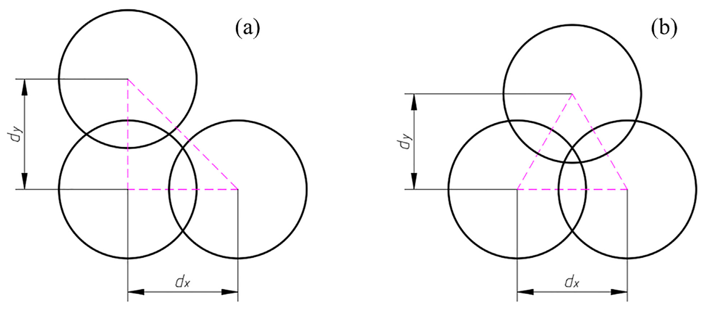
2.3. Surface Morphology Parameters

Micro-geometric surface characteristics of materials have a significant impact on various technical and functional attributes, such as friction and wear behavior, fatigue strength, mating properties, and corrosion resistance of mechanical systems. To characterize the surface morphology of the specimens in this study, we adopt the terminology, definitions, and parameters specified in the ISO 25178−2 standard.
One important parameter used to characterize surface morphology is the arithmetic mean height ( S a ), which represents the average of the absolute ordinate values within a defined area ( A ). It can be calculated using the following equation:
S a = 1 A A | Z ( x , y ) |   d x d y
where A represents the measured region’s area.
Another parameter, S q , is used to quantify the root mean square of the height of each point in the region. It is defined as
S q = 1 A A Z 2 ( x , y )   d x d y
Kurtosis ( S k u ) is a parameter that assesses the flatness of the height distribution. It is calculated as the ratio of the mean quartic value of the ordinate values to the fourth power of S q , as shown in the following equation:
S k u = 1 S q 4 [ 1 A A Z 4 ( x , y ) d x d y ]
Skewness ( S s k ) is a measure of the symmetry of the height distribution and is determined by the quotient of the mean cube value of the ordinate values and the cube of S q :
S s k = 1 S q 3 [ 1 A A Z 3 ( x , y ) d x d y ]
A negative S s k indicates that the surface is composed with principally one plateau and deep and fine valleys. In this case, the distribution is sloping to the top. Conversely, a positive S s k value suggests a surface with lots of peaks on a plane, and the distribution slopes towards the bottom.
The developed interfacial area ratio S d r quantifies the increment in interfacial area of the scale-limited surface within the defined area A . it could be calculated as
S d r = 1 A [ A (   [ 1 + ( z ( x , y ) x ) 2 + ( z ( x , y ) y ) 2 ] 1 ) d x d y ]

3. Results and Discussion

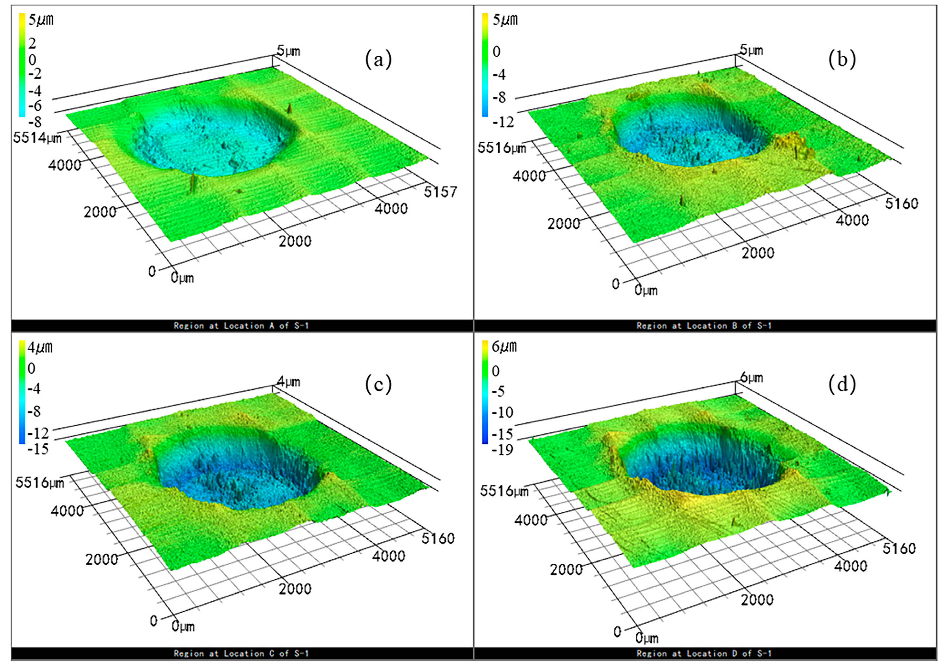
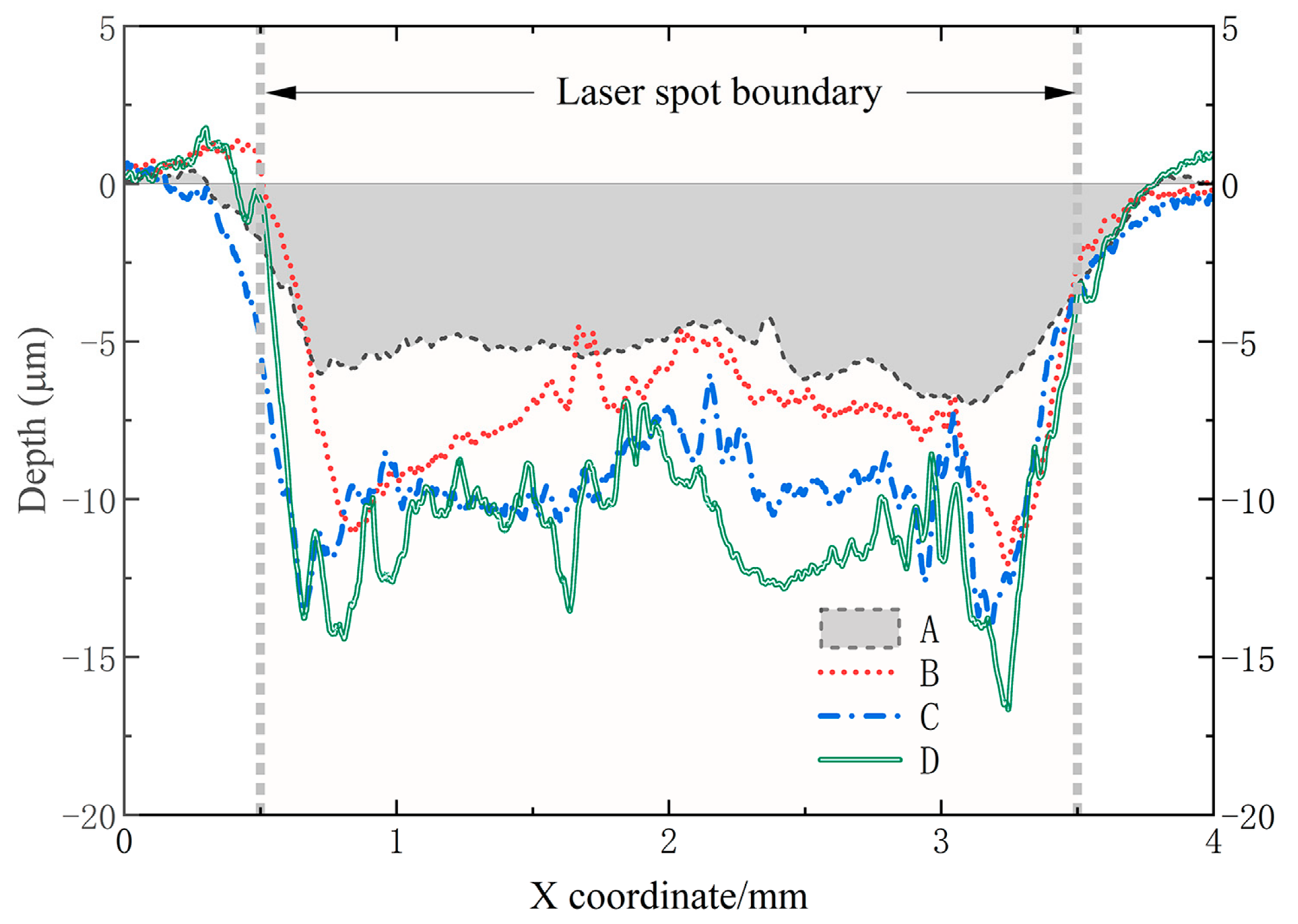
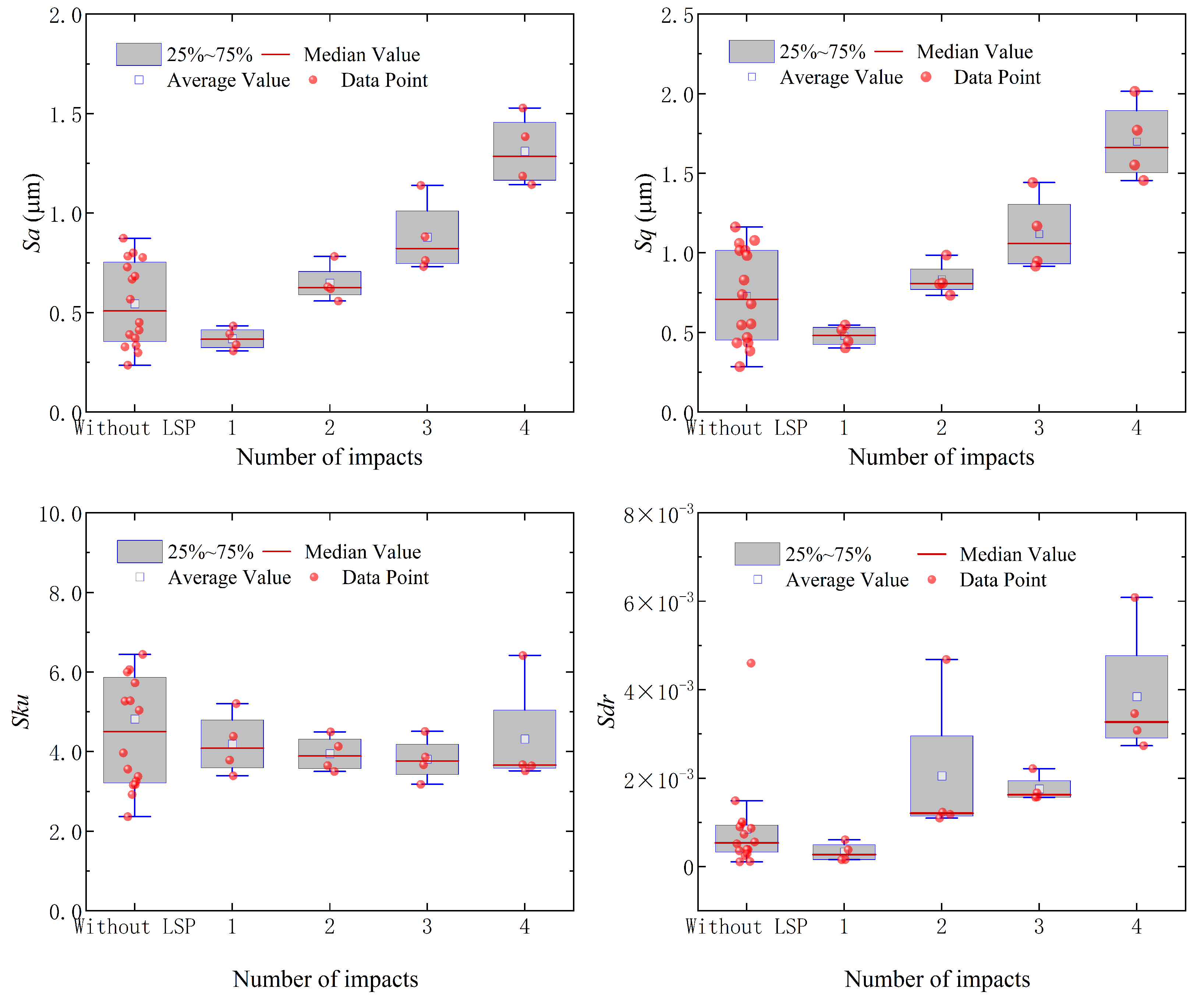
3.1. Surface Morphology in the Single-Point Impact

In this section, we present an analysis and discussion of the surface morphology resulting from single-point repetitive impacts. Specimen S−1 was subjected to a varying number of impacts at different locations. Specifically, point A experienced one impact, while points B, C, and D underwent 2, 3, and 4 impacts, respectively. The surface morphology of rectangular regions surrounding the laser spot centers at points A, B, C, and D were measured to assess the effects of the impacts.
Figure 6 illustrates the surface morphology of specimen S−1 after LSP at locations A, B, C, and D within the rectangular regions centered around the laser spots. Inspection of Figure 6 reveals the presence of both indentations and protrusions on the specimen surfaces, and it is evident that the average depth of the indentations increases with the number of laser impacts. Figure 7 presents the cross-sectional profiles obtained by traversing through the center of the laser spots on specimen S−1. It is indicated in Figure 7 that the maximum depth of the indentations within the laser spot following a single impact was measured at 7.01 μm, with an average depth of approximately 5.29 μm. Additionally, protrusions were observed on the outer edge of the laser spot, exhibiting a maximum height of approximately 0.43 μm in the cross-sectional profile.
To evaluate the average depth of the impacted region, measurements were carried out within a circular area with a radius of 1.25 mm, centered on the laser spots. As illustrated in Figure 8a, the average depth of the indentations resulting from a single impact was found within the range of 5.23 μm to 5.63 μm. Furthermore, with an increase in the number of repeated impacts, the average depth of the indentations exhibited an upward trend. By performing a first-order difference operation on the average depth data obtained from the adjacent laser impacts, the average depth increment data shown in Figure 8b were then obtained. The results in Figure 8b indicate that the initial laser impact exerts the most pronounced influence on the depth increment, while the degree of plastic deformation generated by the latter impact is less than that induced by the anterior impact. This behavior can be attributed to the intense laser-induced plastic deformation and the concurrent cold work hardening effect on the surface layer, which enhances the material’s resistance to plastic deformation.
Upon examination of Figure 6 and Figure 7, it can be observed that the surface within the laser spot appears relatively smooth after a single impact. However, with repetitive impacts, notable alterations in the surface morphology within the indentations become apparent. Surface ablation becomes visible after the third and fourth impacts, as shown in Figure 9. Particularly, a substantial presence of volcano-shaped peaks is observed after four impacts. This occurrence can be attributed to the laser-induced thermal effect, thereby suggesting a potential correlation with the excessively high frequency setting of the laser pulses. Consequently, it becomes apparent that enhancing the final surface performance of the material, such as improved wear resistance, cannot be achieved merely by increasing the number of laser impacts.
Figure 10 illustrates the average residual stress outcomes at the central region and 1 mm away from the center. It can be observed that, after a single impact, the CRS within the central region of the indentations in all four specimens range from approximately −495 MPa to −528 MPa, with slightly lower values observed in the adjacent regions. These shown results also indicate a general increase in CRS magnitude, both at the central and adjacent regions, as the number of impacts increases, while the maximum values do not exceed −632 MPa. Moreover, the CRS within the indentations do not exhibit a linear increase but rather exhibit a gradual and slow increment.
It is noteworthy that the laser-induced plastic deformation extended beyond the boundaries of the laser spots. While indentations are formed within the spots, a subtle ring-shaped protrusion emerges near its outer boundaries. However, it is evident that the reduction in volume resulting from the depressions does not correspond to the “increase” in volume attributable to the protrusions. Examination of the measured data reveals a progressive increase in the volume of the depressions as the number of impacts increases, albeit at a declining rate. Meanwhile, the volume of the raised protrusion also exhibits a tendency to increase, with the ratio of protrusion volume to indentation volume typically remaining below 4%.
A statistical analysis was performed on the surface morphology parameters within a 1.5 mm × 1.5 mm region at the center of the indentations after 1 to 4 LSP impacts, as well as on the surfaces of the specimens without LSP treatment. Based on the arithmetic mean height ( S a ) and root-mean-square height ( S q ) of the specimens shown in Figure 11, it can be observed that the initial smoothness of the surfaces before LSP was favorable, with an average S a value of approximately 0.54 μm. Following a single laser impact, the average S a value slightly decreased to 0.37 μm. However, with an increase in the number of impacts, the S a value exhibited an upward trend. Specifically, after 2, 3, and 4 impacts, the measured values were 0.65 μm, 0.88 μm, and 1.31 μm, respectively. The changes in the parameter S q displayed a consistent trend with S a , where the dispersion between data points increased with the number of impacts. These findings indicate that the surface roughness within the impacted spot increased with the number of impacts. When thermal-induced surface ablation occurred, as illustrated in Figure 9, the change in surface roughness became even more significant. This is further supported by the variation in S a values presented in Figure 11.
Moreover, the average value of Kurtosis ( S k u ) shown in Figure 11 exceeded 3 and gradually decreased, suggesting a height distribution concentration superior to that of a Gaussian surface. However, as the number of impacts increased, the height distribution tended to become more dispersed. For an ideally flat surface, the parameter S d r assumes a value of 0. As illustrated in Figure 11, the increase in laser impacts within the indentations induces an enlargement of the surface area.
The arithmetic mean curvature of the peak ( S p c ) of the specimens is utilized as a representative measure of the average principal curvatures of the surface peaks. A decrease in the S p c value signifies more rounded contact points with other objects, while an increase suggests sharper contact points. The measured data show that the number of impacts can induce variations in the S p c value on the impacted surface, leading to the formation of sharper peaks. These variations would further influence the surface morphology during multiple overlapped impacts, ultimately influencing the wear resistance, sealing performance, and wetting properties of the specimens.

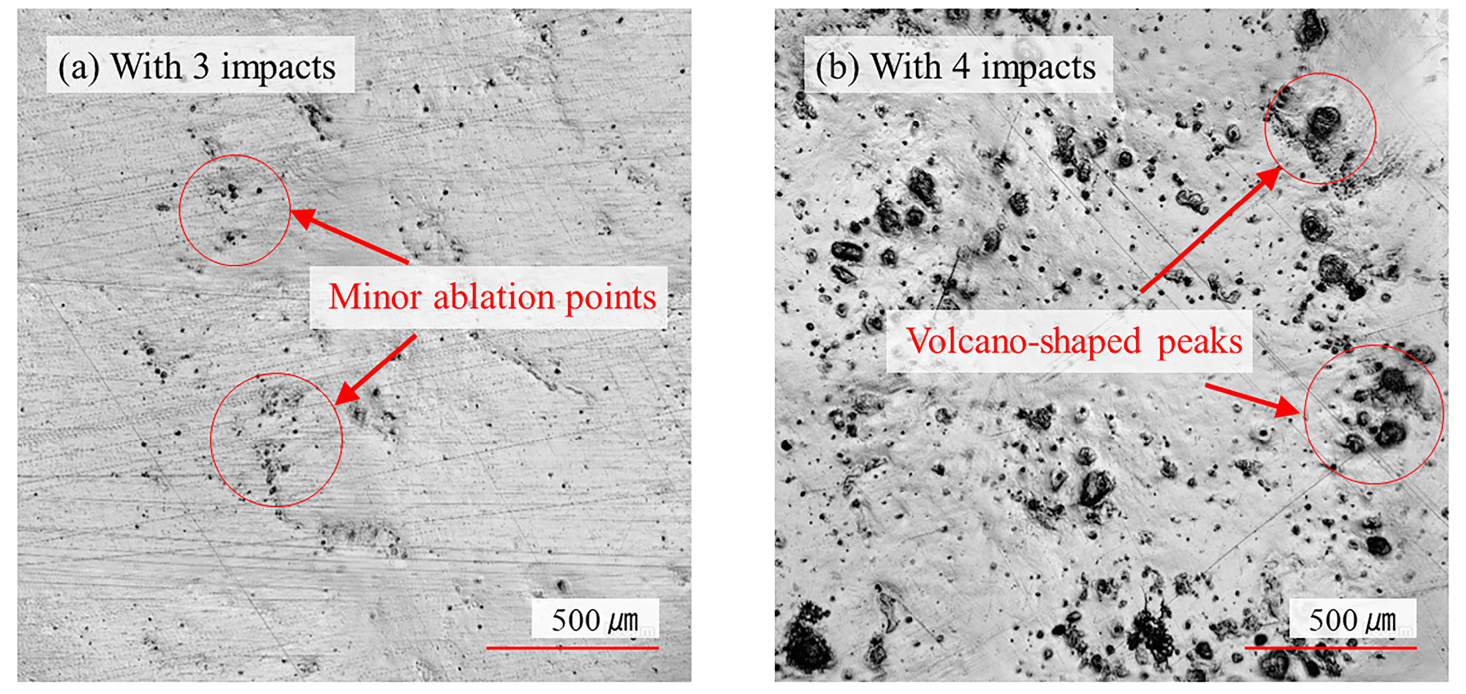
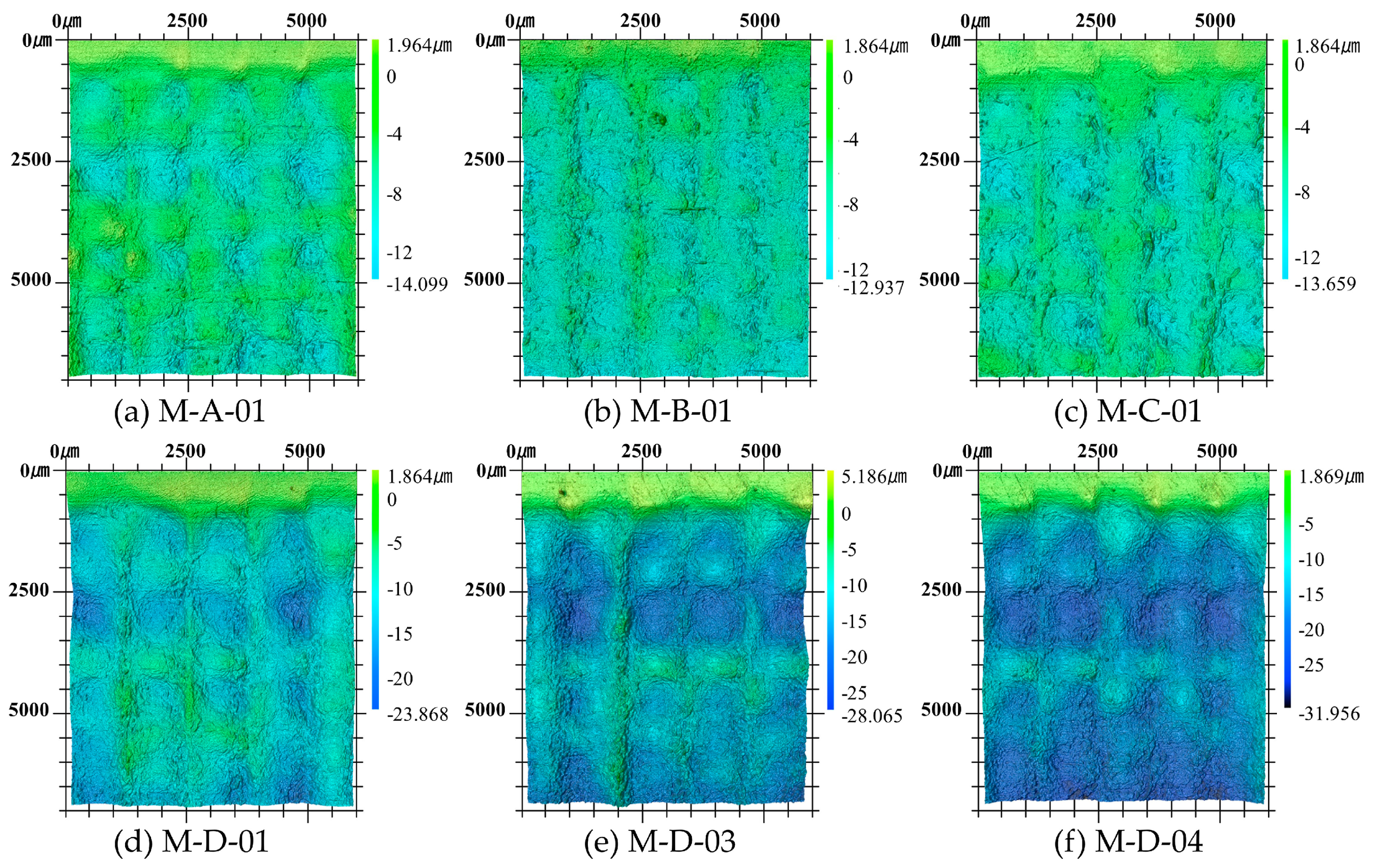
3.2. Surface Morphology in the Multiple Impacts

This section will examine the morphological alterations on the upper surfaces of specimens after multiple impacts. Figure 12a presents a comparative analysis of the surface morphology and the positioning of the laser spot within a selected 6 mm × 7 mm region of specimen M−D−03. Moreover, Figure 12b intuitively illustrates the alterations of the indentations and protrusions within this specific region. It can be observed that the impacted region exhibits an undulating wave-like deformation surface with varying heights. The depths of the depressions exhibit a relatively regular pattern, demonstrating a discernible level of periodicity. Following a single-layer LSP treatment, the number of impacts at locations I, II, III, and IV are 1, 2, 3, and 4, respectively. In the case of double-layer LSP treatment on M−D−03, the number of impacts in these regions is doubled. As a result of experiencing more laser impacts, regions III and IV display deeper indentations, while region II forms raised elevations due to material migration during impact processing.
There exists a significant correlation between the number of impacts and the depth of the indentations within the specific region mentioned above. Typically, regions subjected to a greater number of laser impacts exhibit deeper depressions. However, it is worth noting that the observed contour shape of these depressions does not consistently align with the spot position edge. This inconsistency can be attributed to material migration during the impact process and the additional influence of shock waves on material plastic deformation, resulting in a certain degree of random variation in the shape of the depressions.
The height distribution of surface morphology for some of the specimens is presented in Figure 13. Specifically, Figure 13a–c corresponds to single-layer LSP treatment, while Figure 13d illustrates double-layer LSP treatment of M−D−01. In addition, Figure 13e,f represents triple-layer LSP treatment of specimens M−D−03 and M−D−04. It can be observed from Figure 13 that the average depth of indentations on the surfaces of the M−D group specimens is considerably higher compared to that of the M−A, M−B, and M−C groups.
A statistical analysis was conducted on the surface morphological parameters within a 5 mm × 5 mm region of both the M−O group specimens without LSP and the laser shock peened (LSPed) specimens. As shown in Figure 14a, the average value of the specimens without LSP treatment was approximately 0.07 μm, indicating a relatively smooth surface. However, the average S a values of the M−A, M−B, and M−C group specimens reached approximately 2.06 μm, 1.51 μm, and 1.40 μm, respectively, indicating an evident increase in surface roughness. These changes, in terms of both trend and magnitude, were slightly different from the variations observed within single-point repetitive impact. This divergence can be attributed to the movement of the spot position and the surface compression during multiple impacts, resulting in the formation of multiple indentations arranged in a grid pattern, thereby increasing the waviness and influencing the data results.
In addition, a comparison among the specimens in groups M−A, M−B, and M−C indicated that as the angle α increases, the S a value gradually decreases, suggesting that the angle α has an impact on the smoothness of the surface morphology. During oblique impact, the originally circular shape of the laser spot projected onto the material surface transforms into an elliptical shape, resulting in a change in the laser power density. This alteration subsequently leads to variations in the deformation region of individual laser spots. Therefore, it can be inferred that the change in incident angle inevitably affects the surface morphology, including the direction of texture and the symmetry of local protrusions.
When we consider the specimens in group M−D, it can be observed that an increase in the number of impact layers results in a further rise in surface roughness ( S a ) compared to the previous specimens. Specifically, the average value of S a for the M−D−01 and M−D−02 specimens is measured to be 2.94 μm, while those for the M−D−03 and M−D−04 are 3.39 μm. Moreover, the maximum height ( S z ) in Figure 14b, representing the cumulative sum of the maximum peak height and maximum valley depth within the measured region, exhibits a consistent variation pattern with S a .
Based on the kurtosis ( S k u ) in Figure 14c, it can be observed that the mean value of specimens without LSP reached 11.18. However, after LSP treatment, noticeable changes occurred in the S k u values, falling within the range of 2.54 to 2.89. Moreover, the S k u values among these LSPed specimens appear actually very close. This indicates that the LSP has significantly modified the height distribution of the material surface peaks, resulting in a flatter height distribution curve. Moreover, the height distribution of the surface morphology tends to become more dispersed in relation to the central plane, while still exhibiting characteristics similar to a Gaussian distribution.
The parameter S t r (surface texture ratio) in Figure 14d represents the aspect ratio of surface features, indicating the anisotropy or isotropy of the surface texture. The S t r values should range from 0 to 1, where values close to 0 indicate the presence of directional patterns, while values close to 1 indicate surface independence from direction. In the groups of specimens where the laser was irradiated vertically onto the material surfaces (referred to as M−A and M−D groups), smaller S t r values were observed compared to the other specimens in the M−B and M−C groups. The S t r values in the M−A and M−D groups with single-, double-, and triple-layer LSP were found to be 0.32, 0.32, and 0.28, respectively. This suggests that the morphology of these impacted surfaces exhibits a certain degree of directionality and periodicity. Furthermore, it was found that with the increase in the angle α , the S t r values also increase accordingly, with mean values of 0.32, 0.59, and 0.75, respectively. Therefore, one could find that the increase in the angle α weakens the surface texture directionality and periodicity, which could be unfavorable for situations requiring stable surface lubrication and wear resistance.
Regular and periodic patterns of indentations and protrusions generally have a positive impact on the stability and controllability of the friction system, thereby offering potential for reducing friction coefficients and improving the wear resistance of materials. Additionally, from the analysis of the measured data, it can be observed that the average curvature of the surface vertices without LSP was initially small, with a mean value of 1.60 mm−1. However, after the LSP impacts, all mean values exceeded 10 mm−1, indicating that the LSP treatment induces sharpening of the material surface vertices, and the increase in impact times typically leads to a corresponding increase in this parameter value.

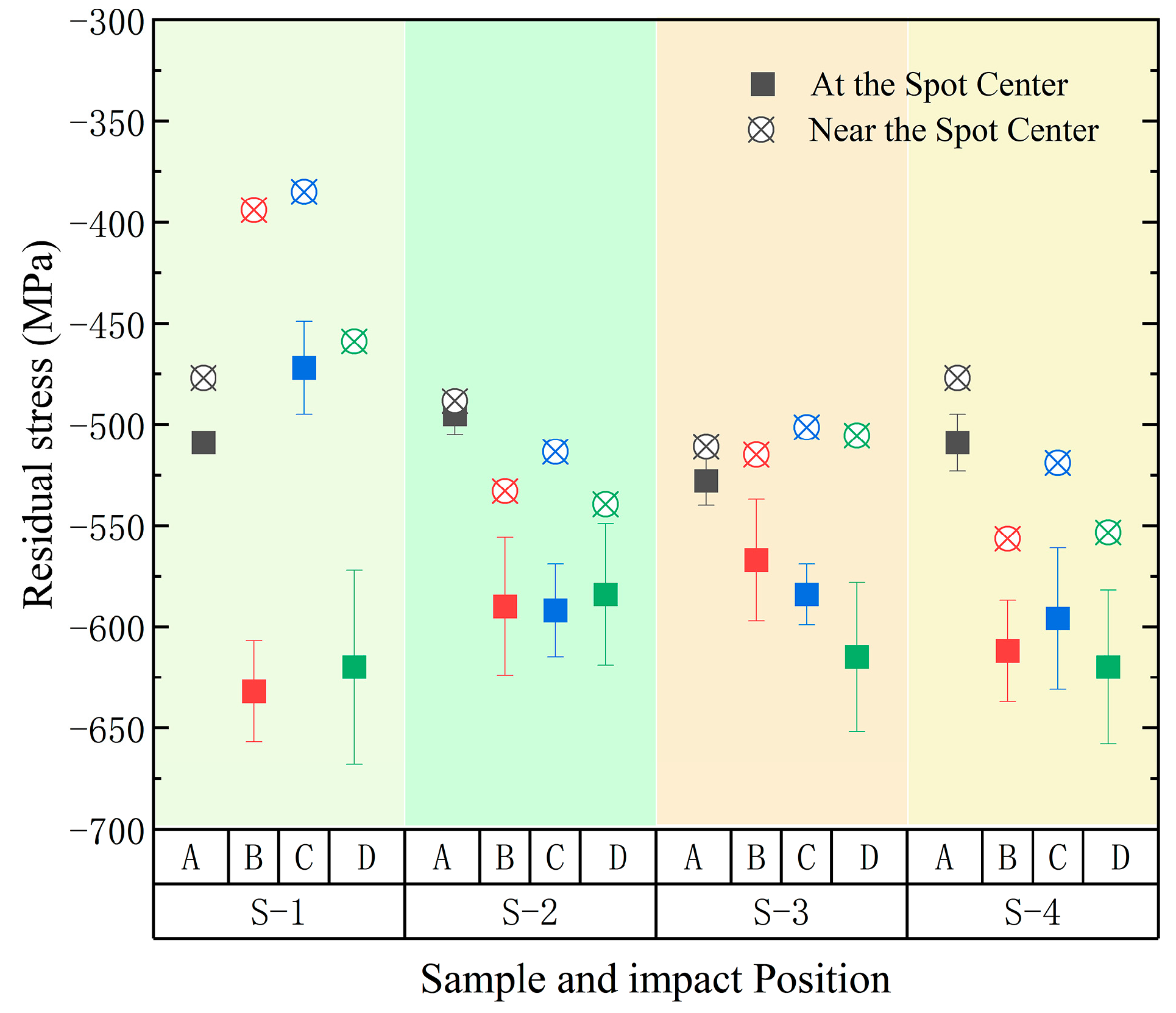
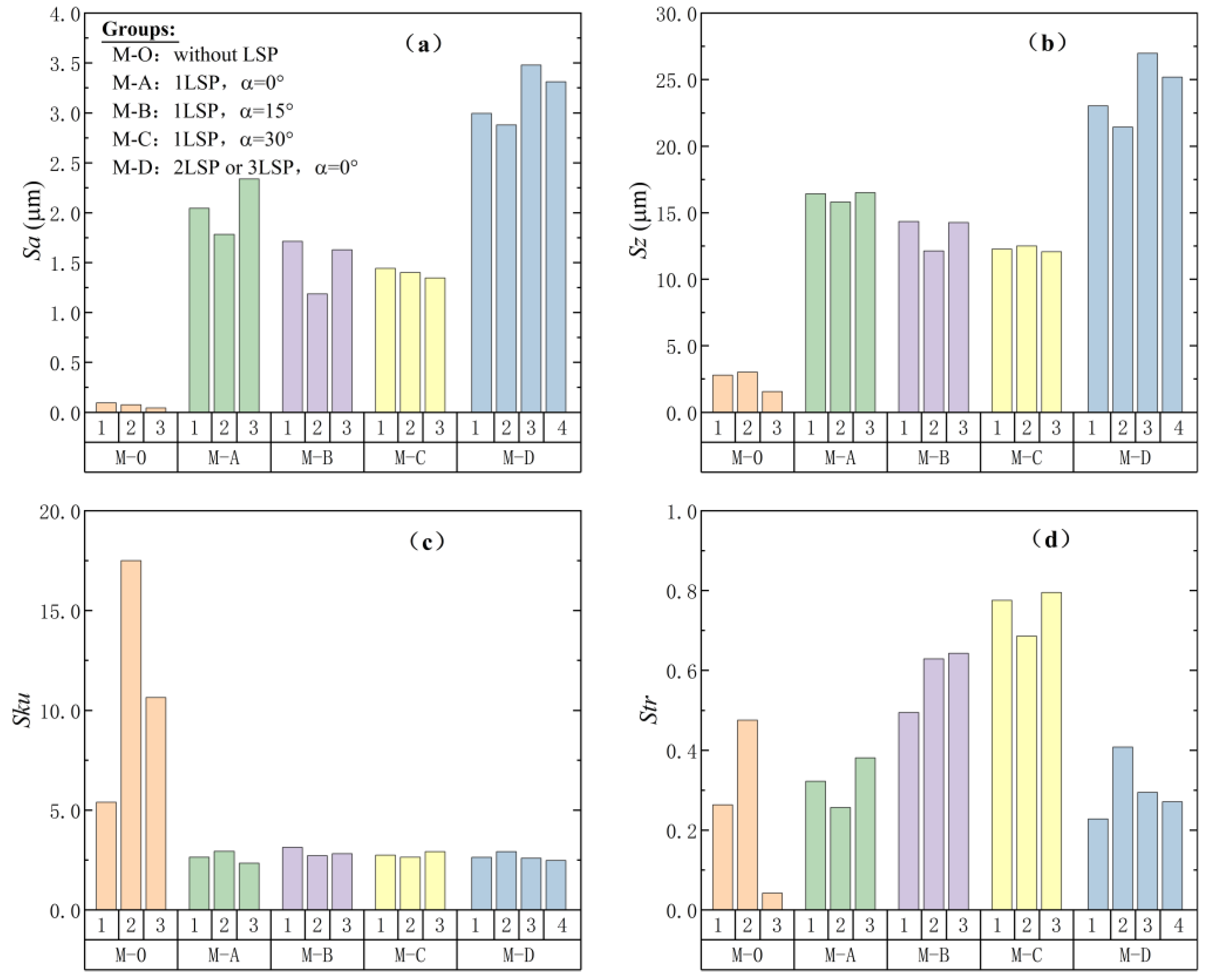
3.3. Evaluation of Impact Stacking Methods and Their Effects

The surface roughness resulting from multiple overlapped LSP impact is influenced by various factors, including laser processing parameters and material characteristics. In order to analyze and assess laser-induced surface morphology issues, some researchers have resorted to employing theoretical analyses and methodologies involving the finite element method (FEM), notwithstanding the computational complexity involved. However, in this paper, we only focus on the effects of different impact stacking methods by utilizing simplified impact patterns for evaluation purposes.
In the multiple overlapped LSP impact experiments conducted, it was ensured that the impact regions strictly overlapped during the double-layer and triple-layer LSP treatment. As shown in Figure 15a, this resulted in zero displacements in both the transverse and longitudinal directions of the impact region among layers of the LSP treatment. Within the laser spot, the regions can be categorized into three types, denoted as Type IV, Type VI, and Type VIII, based on the number of laser impacts. These types correspond to the regions that have undergone 4, 6, and 8 impacts, respectively, following the double-layer LSP treatment. The area ratios of these types to the overall spot area are 11.05%, 48.83%, and 40.13%. However, it should be noted that the area ratio within the spot does not accurately represent the area ratio within the entire impact region. Therefore, the outer circumscribed square of the spot profile was considered, and the area ratios of the impact region within the outer circumscribed square are listed in Table 5.
If the impact region moves laterally by R/2 (where R represents the spot radius) during the second layer impacts, the pattern of impact region is shown as Figure 15b. In this case, the regions labeled as IV, V, VI, VII, and VIII within the laser spot correspond to 4, 5, 6, 7, and 8 impacts. The area ratios of these types of regions to the impact region are listed in the row corresponding to Type A in Table 5. Similarly, if the impact region undergoes a lateral displacement of R/2 and a vertical displacement of R/2 in the second layer impacts, the pattern of impact region is illustrated in Figure 15c. In this case, the regions within the spot can be categorized as Type IV, Type V, Type VI, and Type VII, representing 4, 5, 6, and 7 impacts, respectively. The area ratios of these types of regions are 9.36%, 4.54%, 34.52%, and 51.58%, respectively.
The experimental results mentioned above indicate a positive correlation between the extent of plastic deformation and the number of laser impacts. Therefore, it can be argued that when multiple layers of overlapped impacts are applied, not only the overlapping rate and the scanning path within a single layer of impacts should be taken into account but also the displacement of spots among layers of impacts. These adjustments aim to reduce the height difference between indentations and protrusions, thus achieving a smoother surface and enhancing the material’s frictional and wear performance under specific conditions.
Taking the specimens of the M−D−01 and M−D−02 as illustrative examples, the regions labeled as VIII experienced a total of eight impacts with an area ratio of 31.51% (as shown in Table 5) after completing the double-layer LSP treatment. Although this may suggest that these localized regions experienced a greater extent of plastic deformation and surface hardening, it concurrently resulted in an increased difference in height between the indentations and protrusions on the material surface, as well as intensified surface ripple variations. Consequently, this exacerbation of surface irregularities may not result in the desired improvement in the material’s wear resistance.
When examining the directional characteristics of the impact patterns, it can be observed that the Type A pattern exhibits periodic variations in both horizontal and vertical directions. Specifically, the horizontal period is R/2, while the vertical period is R. Therefore, it can be anticipated that the resulting surface texture from this particular type of impact will exhibit significant directional characteristics in both the vertical and horizontal directions. In contrast, the impact patterns of Type N and Type B exhibit symmetrical properties in both the horizontal and vertical directions, with a consistent period of R. Additionally, these patterns also demonstrate symmetry at 45°and 135° directions. Thus, it can be inferred that these impact patterns exhibit relatively favorable “anisotropy” in terms of their directional characteristics.
The assessment of surface deformation after LSP treatment is often challenging and could lead to inconsistent results due to the inherent complexity involved. To obtain a more comprehensive understanding of the variations in surfaces, it is advisable to consider the following aspects: (1) the periodicity and symmetry of the impact patterns, (2) the minimum period and complexity exhibited by these patterns, (3) the number of distinct types of impact regions, (4) the area ratio corresponding to each major region type, and (5) the gradient and maximum disparity in the number of laser impacts experienced by different surface regions. Through a comprehensive examination of these factors, a more comprehensive understanding of surface deformation could be achieved.
Regarding the three types mentioned above, Type B and Type N exhibit periodic variations in both horizontal and vertical directions, thereby demonstrating favorable anisotropic characteristics. In terms of the pattern complexity of impacts, the fractal dimensions, as measured by the box counting method, are approximately 1.34, 1.52, and 1.51 for Type N, Type A, and Type B, respectively. Thus, Type A patterns are deemed to possess a higher degree of complexity. Considering the gradient and maximum disparity in the number of impacts, it can be observed that region VII within Type B covers 51.58% of the total impacted region and exhibits a maximum difference of three impacts, while the adjacent region VI accounts for 34.52% of the area. This suggests that the impact pattern of Type B may hold an advantage in terms of achieving superior surface smoothness after laser impacts.
However, the actual performance of these surfaces remains uncertain and highly reliant on the specific lubrication conditions and application fields. Therefore, further investigation is needed to gain a more comprehensive understanding of these crucial aspects.

3.4. Discussion

Our findings align with the reported correlation between the number of laser impacts and superficial residual stress, as well as material plastic deformation in Ref. [2]. However, it should be noted that an increase in residual stress does not always result in improved impact effects, especially in applications involving friction and wear, where performance is influenced by additional factors like surface roughness.
Many researchers, including Spadaro et al. [18] and Cellard et al. [36], have investigated the effect of LSP on surface morphology. However, there is an insufficient use of surface roughness parameters in these studies. Most of these studies focus on 2D and 3D surface roughness parameters of average roughness ( R a / S a ), maximum height of the profile ( R z / S z ), and root mean square roughness ( R q / S q ). Nevertheless, Siddaiah et al. [9] and Menezes et al. [37,38] argue that one or two surface roughness parameters are insufficient to quantify the topographical changes observed on a given surface and to describe the functional characteristic like friction.
While Cellard et al. [36] reported no influence of laser shock peening treatment parameters on roughness in aTi-17 titanium alloy, our results reveal that when measured on a macroscopic scale, specific 3D morphological parameters like S a exhibits a strong correlation with the number of laser impacts. Moreover, the Str parameter is significantly influenced by the laser incidence angle. Consequently, our study emphasizes the importance and necessity of utilizing multiple 3D morphological parameters to characterize LSPed surface morphology, thereby corroborating the perspective of Siddaiah and Menezes et al. [9,37,38].
Siddaiah et al. [9] and Trdan et al. [39] also employed 3D morphological parameters to characterize LSPed surface morphology, with a primary focus on investigating the influence of laser intensity. However, it is evident that our work specifically investigates the impact of the number of laser impacts on surface morphology. Additionally, the material of the specimens, LSP parameters, and selection of 3D morphological parameters differ between our work and theirs. Our findings suggests that parameters such as Str and the average curvature of surface vertices should be taken into consideration for a comprehensive characterization of surface morphology.
To achieve the desired impact effect and surface morphology, researchers often endeavor to optimize LSP parameters or design appropriate shock procedures. The approach proposed in this study of integrating impact patterns into the evaluation of LSPed surface morphology variations provides new insights into reducing the need for complex post-analysis and numerical simulations. However, owing to the intricate nature of laser shock effects and morphology characterization, further research is required to develop evaluation methods adapted to specific application domains, such as anti-wear design and anti-fatigue design.

4. Conclusions

This study investigated and discussed the effects of single-point repetitive and multiple overlapped laser shock peening (LSP) on the surface morphology of 20CrMnTi steel. The findings reveal the following:
(1)
The plastic deformation induced by LSP showed a positive correlation with the number of laser impacts. Additionally, LSP treatment resulted in changes in surface morphology, distribution, and an increase in surface roughness.
(2)
Multiple impacts led to the formation of a wave-like pattern of indentations, where the directionality and periodicity of the surface texture were influenced by the laser incidence angle used during the LSP process.
(3)
The integration of 3D morphological parameters provides valuable insights into surface characterization and should be considered when evaluating laser shock processed surfaces. However, further research is needed to develop evaluation methods tailored to specific application areas.
(4)
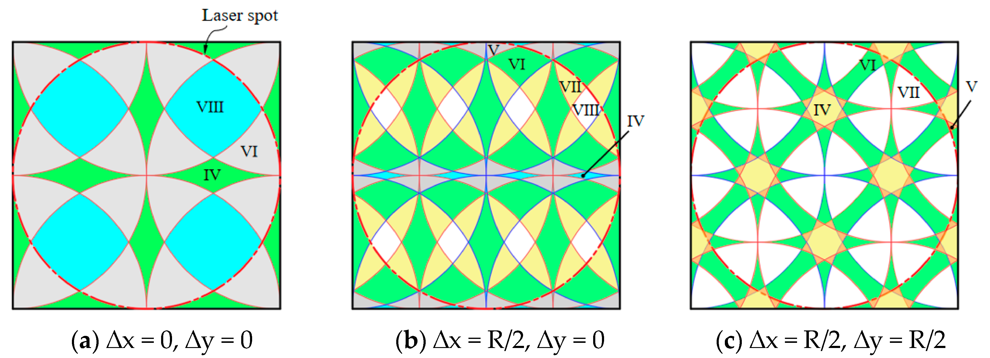
The impact patterns can be utilized to evaluate surface morphology variations resulting from LSP treatment, suggesting the potential for strategically adjusting the shock region’s position to effectively reduce height differences on impacted surfaces.
(5)
For a more comprehensive exploration of the surface morphology characteristics induced by LSP, several aspects, including periodicity, symmetry, complexity, and minimum period exhibited by the impact patterns, should be taken into consideration.

Author Contributions

Conceptualization, J.W. and D.Z.; methodology, J.W. and X.W.; validation, D.Z. and X.W.; formal analysis, J.W.; investigation and resources, J.W.; data curation, J.W. and X.W.; writing—original draft preparation, J.W.; writing—review and editing, D.Z.; visualization, J.W.; supervision, D.Z.; project administration, J.W.; funding acquisition, J.W. All authors have read and agreed to the published version of the manuscript.

Funding

This research was funded by Natural Science Foundation of Jiangsu Province (grant number: BK20190846) and Zhenjiang Key Research and Development Program (Industry Foresight and Common Key Technologies, grant number: GY2023018).

Data Availability Statement

The data used to support the findings of this study are available from the corresponding author upon request.

Acknowledgments

We would like to express our gratitude to all the individuals and organizations who have contributed to the completion of this research project. In particular, we are grateful to Natural Science Foundation of Jiangsu Province (grant number: BK20190846) and Zhenjiang Key Research and Development Program (Industry Foresight and Common Key Technologies, grant number: GY2023018) for providing financial support.

Conflicts of Interest

The authors declare no conflict of interest.

References

  1. Tang, J.; Fu, X.; Lai, Q.; Guo, X.; Qu, S.; He, R.; Qin, S.; Li, J. Evolution of Fretting Wear Behaviors and Mechanisms of 20CrMnTi Steel after Carburizing. Metals 2020, 10, 179. [Google Scholar] [CrossRef]
  2. Deng, W.; Wang, C.; Lu, H.; Meng, X.; Wang, Z.; Lv, J.; Luo, K.; Lu, J. Progressive developments, challenges and future trends in laser shock peening of metallic materials and alloys: A comprehensive review. Int. J. Mach. Tools Manuf. 2023, 191, 104061. [Google Scholar] [CrossRef]
  3. Bikdeloo, R.; Farrahi, G.; Mehmanparast, A.; Mahdavi, S. Multiple laser shock peening effects on residual stress distribution and fatigue crack growth behaviour of 316L stainless steel. Theor. Appl. Fract. Mech. 2020, 105, 102429. [Google Scholar] [CrossRef]
  4. John, M.; Ralls, A.M.; Kuruveri, U.B.; Menezes, P.L. Tribological, corrosion, and microstructural features of laser-shock-peened steels. Metals 2023, 13, 397. [Google Scholar] [CrossRef]
  5. Pavan, M.; Furfari, D.; Ahmad, B.; Gharghouri, M.A.; Fitzpatrick, M.E. Fatigue crack growth in a laser shock peened residual stress field. Int. J. Fatigue. 2019, 123, 157–167. [Google Scholar] [CrossRef]
  6. Wan, Z.; Dai, W.; Guo, W.; Jia, Q.; Zhang, H.; Xue, J.; Lin, L.; Peng, P. Improved corrosion resistance of Ni-base Alloy 600 welded joint by laser shock peening. J. Manuf. Process. 2022, 80, 718–728. [Google Scholar] [CrossRef]
  7. Zhang, R.; Mankoci, S.; Walters, N.; Gao, H.; Zhang, H.; Hou, X.; Qin, H.; Ren, Z.; Zhou, X.; Doll, G.L.; et al. Effects of laser shock peening on the corrosion behavior and biocompatibility of a nickel-titanium alloy. J. Biomed. Mater. Res. Part B 2019, 107, 1854–1863. [Google Scholar] [CrossRef] [PubMed]
  8. Shen, X.; Shukla, P.; Swanson, P.; An, Z.; Prabhakaran, S.; Waugh, D.; Nie, X.; Mee, C.; Nakhodchi, S.; Lawrence, J. Altering the wetting properties of orthopaedic titanium alloy (Ti-6Al-7Nb) using laser shock peening. J. Alloys Compd. 2019, 801, 327–342. [Google Scholar] [CrossRef]
  9. Siddaiah, A.; Mao, B.; Liao, Y.; Menezes, P.L. Surface characterization and tribological performance of laser shock peened steel surfaces. Surf. Coat. Technol. 2018, 351, 188–197. [Google Scholar] [CrossRef]
  10. Siddaiah, A.; Mao, B.; Kasar, A.; Liao, Y.; Menezes, P. Influence of laser shock peening on the surface energy and tribocorrosion properties of an AZ31B Mg alloy. Wear 2020, 462–463, 203490. [Google Scholar] [CrossRef]
  11. Rubio, G.C.; Ocana, J.L.; Gomez, R.G.; Molpeceres, C.; Paredes, M.; Banderas, A.; Porro, J.; Morales, M. Effect of laser shock processing on fatigue crack growth and fracture toughness of 6061-T6 aluminum alloy. Mater. Sci. Eng. A Struct. Mater. Prop. Microstruct. Process. 2004, 386, 291–295. [Google Scholar] [CrossRef]
  12. Dhakal, B.; Swaroop, S. Effect of laser shock peening on mechanical and microstructural aspects of 6061-T6 aluminum alloy. J. Mater. Process. Technol. 2020, 282, 116640. [Google Scholar] [CrossRef]
  13. Montross, C.; Wei, T.; Ye, L.; Clark, G.; Mai, Y. Laser shock processing and its effects on microstructure and properties of metal alloys: A review. Int. J. Fatigue 2002, 24, 1021–1036. [Google Scholar] [CrossRef]
  14. Kattoura, M.; Mannava, S.R.; Qian, D.; Vasudevan, V.K. Effect of laser shock peening on residual stress, microstructure and fatigue behavior of ATI 718Plus alloy. Int. J. Fatigue 2017, 102, 121–134. [Google Scholar] [CrossRef]
  15. Tong, Z.; Liu, H.; Jiao, J.; Zhou, W.; Yang, Y.; Ren, X. Microstructure, microhardness and residual stress of laser additive manufactured CoCrFeMnNi high -entropy alloy subjected to laser shock peening. J. Mater. Process. Technol. 2020, 285, 116806. [Google Scholar] [CrossRef]
  16. Yang, J.; Her, Y.; Han, N.; Clauer, A. Laser shock peening on fatigue behavior of 2024-T3 Al alloy with fastener holes and stopholes. Mater. Sci. Eng. A Struct. Mater. Prop. Microstruct. Process. 2001, 298, 296–299. [Google Scholar] [CrossRef]
  17. Bakhtiari, M.; Khanigi, A.; Seyed-Salehi, M.; Farnia, A. Ti6Al4V Bone Implants: Effect of Laser Shock Peening on Physical, Mechanical, and Biological Properties. Mater. Eng. Perform. 2023. [Google Scholar] [CrossRef]
  18. Spadaro, L.; Herenu, S.; Strubbia, R.; Rosas, G.G.; Bolmaro, R.; Gonzalez, C.R. Effects of laser shock processing and shot peening on 253 MA austenitic stainless steel and their consequences on fatigue properties. Opt. Laser Technol. 2020, 122, 105892. [Google Scholar] [CrossRef]
  19. Chattopadhyay, A.; Muvvala, G.; Sarkar, S.; Racherla, V.; Nath, A.K. Effect of laser shock peening on microstructural, mechanical and corrosion properties of laser beam welded commercially pure titanium. Opt. Laser Technol. 2021, 133, 106527. [Google Scholar] [CrossRef]
  20. Caralapatti, V.; Narayanswamy, S. Effect of high repetition laser shock peening on biocompatibility and corrosion resistance of magnesium. Opt. Laser Technol. 2017, 88, 75–84. [Google Scholar] [CrossRef]
  21. Yoo, Y.R.; Choi, S.H.; Kim, Y.S. Effect of laser shock peening on the stress corrosion cracking of 304L stainless steel. Metals 2023, 13, 30516. [Google Scholar] [CrossRef]
  22. Park, J.; Yeo, I.; Jang, I.; Jeong, S. Improvement of friction characteristics of cast aluminum-silicon alloy by laser shock peening. J. Mater. Process. Technol. 2019, 266, 283–291. [Google Scholar] [CrossRef]
  23. Sanchez-Santana, U.; Rubio-Gonzalez, C.; Gomez-Rosas, G.; Ocana, J.; Molpeceres, C.; Porro, J.; Morales, M. Wear and friction of 6061-T6 aluminum alloy treated by laser shock processing. Wear 2006, 260, 847–854. [Google Scholar] [CrossRef]
  24. Praveenkumar, K.; Swaroop, S.; Manivasagam, G. Effect of multiple laser shock peening without coating on residual stress distribution and high temperature dry sliding wear behaviour of Ti-6Al-4 V alloy. Opt. Laser Technol. 2023, 164, 109398. [Google Scholar] [CrossRef]
  25. Hareharen, K.; Kumar, S.; Panneerselvam, T.; Babu, P.; Sriraman, N. Investigating the effect of laser shock peening on the wear behaviour of selective laser melted 316L stainless steel. Opt. Laser Technol. 2023, 162, 109317. [Google Scholar] [CrossRef]
  26. Tong, Z.; Ren, X.; Zhou, W.; Adu-Gyamfi, S.; Chen, L.; Ye, Y.; Ren, Y.; Dai, F.; Yang, J.; Li, L. Effect of laser shock peening on wear behaviors of TC11 alloy at elevated temperature. Opt. Laser Technol. 2019, 109, 139–148. [Google Scholar] [CrossRef]
  27. Gill, A.S.; Telang, A.; Ye, C.; Mannava, S.R.; Qian, D.; Vasudevan, V.K. Localized plastic deformation and hardening in laser shock peened Inconel alloy 718SPF. Mater. Charact. 2018, 142, 15–26. [Google Scholar] [CrossRef]
  28. Halilovic, M.; Issa, S.; Wallin, M.; Hallberg, H.; Ristinmaa, M. Prediction of the residual state in 304 austenitic steel after laser shock peening—Effects of plastic deformation and martensitic phase transformation. Int. J. Mech. Sci. 2016, 111, 24–34. [Google Scholar] [CrossRef]
  29. Hfaiedh, N.; Peyre, P.; Song, H.; Popa, I.; Ji, V.; Vignal, V. Finite element analysis of laser shock peening of 2050-T8 aluminum alloy. Int. J. Fatigue. 2015, 70, 480–489. [Google Scholar] [CrossRef]
  30. Nataraj, M.; Swaroop, S. Effects of power density on residual stress and microstructural behavior of Ti-2.5Cu alloy by laser shock peening without coating. Vacuum 2023, 213, 112078. [Google Scholar] [CrossRef]
  31. Maawad, E.; Sano, Y.; Wagner, L.; Brokmeier, H.; Genzel, C. Investigation of laser shock peening effects on residual stress state and fatigue performance of titanium alloys. Mater. Sci. Eng. A Struct. Mater. Prop. Microstruct. Process. 2012, 536, 82–91. [Google Scholar] [CrossRef]
  32. Laine, S.; Knowles, K.; Doorbar, P.; Cutts, R.; Rugg, D. Microstructural characterisation of metallic shot peened and laser shock peened Ti-6Al-4V. Acta Mater. 2017, 123, 350–361. [Google Scholar] [CrossRef]
  33. Prabhakaran, S.; Kalainathan, S.; Shukla, P.; Vasudevan, V. Residual stress, phase, microstructure and mechanical property studies of ultrafine bainitic steel through laser shock peening. Opt. Laser Technol. 2019, 115, 447–458. [Google Scholar] [CrossRef]
  34. Wu, L.; Luo, K.; Liu, Y.; Cui, C.; Xue, W.; Lu, J. Effects of laser shock peening on the micro-hardness, tensile properties, and fracture morphologies of CP-Ti alloy at different temperatures. Appl. Surf. Sci. 2018, 431, 122–134. [Google Scholar] [CrossRef]
  35. Rai, A.; Biswal, R.; Gupta, R.; Singh, R.; Rai, S.; Ranganathan, K.; Ganesh, P.; Kaul, R.; Bindra, K. Study on the effect of multiple laser shock peening on residual stress and microstructural changes in modified 9Cr-1Mo (P91) steel. Surf. Coat. Technol. 2019, 358, 125–135. [Google Scholar] [CrossRef]
  36. Cellard, C.; Retraint, D.; Francois, M.; Rouhaud, E.; Le Saunier, D. Laser shock peening of Ti-17 titanium alloy: Influence of process parameters. Mater. Sci. Eng. A Struct. Mater. Prop. Microstruct. Process. 2012, 532, 362–372. [Google Scholar] [CrossRef]
  37. Menezes, P.; Kishorea; Kailas, S. Influence of surface texture and roughness parameters on friction and transfer layer formation during sliding of aluminium pin on steel plate. Wear 2009, 267, 1534–1549. [Google Scholar] [CrossRef]
  38. Menezes, P.; Kishore; Kailas, S. On the effect of surface texture on friction and transfer layer formation-A study using Al and steel pair. Wear 2008, 265, 1655–1669. [Google Scholar] [CrossRef]
  39. Trdan, U.; Porro, J.; Ocana, J.; Grum, J. Laser shock peening without absorbent coating (LSPwC) effect on 3D surface topography and mechanical properties of 6082-T651 Al alloy. Surf. Coat. Technol. 2012, 208, 109–116. [Google Scholar] [CrossRef]
Figure 1. Appearance of the treated specimens prior to LSP.
Metals 13 01673 g001
Figure 2. Schematic diagram of LSP processing. Circular spots were utilized, with laser intensity following a Gaussian distribution. The aluminum foil serves as the absorbing layer, while the water film acts as the confining layer.
Metals 13 01673 g002
Figure 3. Impact positions and residual stress measurement points in single-point repetitive LSP. (a) Specimen subjected to repeated impacts at positions A, B, C, and D; (b) Residual stress measurement points: center point denoted as Mc and four points situated 1 mm away from the center denoted as M1, M2, M3, and M4.
Metals 13 01673 g003
Figure 4. The two commonly used overlapping styles in LSP treatment: (a) isosceles triangle style and (b) equilateral triangle style.
Metals 13 01673 g004
Figure 5. The shock region and scanning path in multiple LSP processing. (a) The incident angle of the laser is denoted by angle α; (b) The scanning path follows an ‘S’ pattern, where the laser moves in a straight line from the starting point and then turns back in the next line to treat the entire area.
Metals 13 01673 g005
Figure 6. The surface morphology in different regions within the specimen S−1. (a) Point A underwent a single impact, while (bd) represent points B, C, and D, which underwent 2, 3, and 4 impacts, respectively.
Metals 13 01673 g006
Figure 7. Surface profile of indentations with LSP on specimen S−1.
Metals 13 01673 g007
Figure 8. Average depth and depth increment of the impacted regions. (a) Average indentation depth increases with the number of impacts; (b) Initial impact has the greatest influence on depth increment, and subsequent impacts induce less plastic deformation.
Metals 13 01673 g008
Figure 9. Surface ablation in laser-impacted regions of S−1 visualized using the confocal laser scanning microscope VK−X250K. (a) Image captured at location C with three impacts, illustrating several minor dispersed ablation points. (b) Image captured at location D with four impacts, revealing a considerable number of severe volcano-shaped peaks.
Metals 13 01673 g009
Figure 10. Residual stress on the surfaces of indentations with LSP.
Metals 13 01673 g010
Figure 11. Morphology parameters in the single-point repetitive impact.
Metals 13 01673 g011
Figure 12. The surface morphology and spot position within the M−D−03. (a) The comparison between the spot location and the surface morphology; (b) 3D surface morphology within the specific region.
Metals 13 01673 g012
Figure 13. Height distribution of surface morphology of specimens. (ac) correspond to single-layer LSP, while (d) illustrates double-layer LSP of M−D−01. Moreover, (e,f) represent triple-layer LSP of specimens M−D−03 and M−D−04.
Metals 13 01673 g013
Figure 14. Bar charts of the surface morphology parameters in the multiple impacts. (a) Sa (b) Sz (c) Sku (d) Str.
Metals 13 01673 g014
Figure 15. The patterns of impact region under different impact stacking methods. (a) No displacements; (b) With region moves laterally by R/2; (c) With region moves by R/2 in both the longitudinal and transverse directions.
Metals 13 01673 g015
Table 1. Main composition of 20CrMnTi steel (wt.%).
CSiMnPSCrTiNiCuN
0.1900.2700.9000.0110.0071.000.0570.0160.0180.005
Table 2. The physical and mechanical properties of 20CrMnTi steel.
Density
(kg/m3)
Tensile Strength
(MPa)
Yield Strength
(MPa)
Elastic Modulus
(GPa)
Poisson’s RatioCoefficient of Thermal Expansion(/K)
7.8 × 10310808352070.251.3 × 10−5
Table 3. Parameters for laser shock peening.
WavelengthEnergySpot DiameterPulse WidthAblative LayerConfining LayerOverlapping Rate
1064 nm9 J3 mm20 nsAl. FoilWater film50%
Table 4. Information list of specimens for LSP treatment.
LSP ExperimentSpecimen NumberIncident AngleType
Single-point repetitive impactsS−1, S−2, S−3, S−4/
Multiple impactsM−A−01, M−A−02, M−A−03Single-layer
M−B−01, M−B−02, M−B−0315°Single-layer
M−C−01, M−C−02, M−C−0330°Single-layer
M−D−01, M−D−02Double-layer
M−D−03, M−D−04Triple-layer
Table 5. The area ratios of the impact region within the outer circumscribed square.
Overlapping TypeDisplacementArea Ratio (%)
∆x∆y
N0017.360.0051.130.0031.51
AR/202.4112.8846.7129.988.02
BR/2R/29.364.5434.5251.580.00
Disclaimer/Publisher’s Note: The statements, opinions and data contained in all publications are solely those of the individual author(s) and contributor(s) and not of MDPI and/or the editor(s). MDPI and/or the editor(s) disclaim responsibility for any injury to people or property resulting from any ideas, methods, instructions or products referred to in the content.

