Article

Heat Treatment Induced Structural Transformations and High-Temperature Oxidation Behavior of Al21Co22Cr22Fe13Ni22 High-Entropy Coatings Produced by Non-Vacuum Electron Beam Cladding

1
Faculty of Mechanical Engineering and Technologies, Novosibirsk State Technical University, K. Marx Ave. 20, 630073 Novosibirsk, Russia
2
Synchrotron Radiation Facility SKIF, Boreskov Institute of Catalysis, Nikol’sky Ave., 1, 630559 Kol’tsovo, Russia
3
Budker Institute of Nuclear Physics, Lavrentyev Ave. 11, 630090 Novosibirsk, Russia
*
Author to whom correspondence should be addressed.
Metals 2023, 13(10), 1689; https://doi.org/10.3390/met13101689
Submission received: 30 August 2023 / Revised: 27 September 2023 / Accepted: 29 September 2023 / Published: 3 October 2023
(This article belongs to the Section Metal Casting, Forming and Heat Treatment)

Abstract

:
In this study, Al21Co22Cr22Fe13Ni22 high-entropy coatings were produced on steel substrates by non-vacuum electron beam cladding of Co, Cr, and NiAl powders. The high-temperature oxidation behavior of the coatings was studied by holding the specimens at 900 °C in air. The microstructure and phase constitution of the samples were studied both in the as-cladded state and after the heat treatment. The microstructure was characterized using light microscopy (LM) and scanning electron microscopy (SEM). Synchrotron X-ray diffraction (SXRD) and energy-dispersive X-ray spectroscopy (EDX) were used to study the phase constitution of the coatings and the “coating-substrate” interface. The coating consisted of disordered bcc (A2), ordered bcc (B2), and disordered fcc (A1) phases. Annealing the coatings for 50 h at 900 °C led to the formation of fcc precipitates in the bcc dendritic grains and a mixture of fcc and σ-phase particles in the interdendritic regions. Needle-like nanosized B2-precipitates were formed due to annealing in the fcc grains at the coating/substrate interface. The microhardness at the top of the as-cladded coating was 585 HV and gradually decreased towards the substrate. A more uniform distribution of the microhardness was obtained after the annealing. Its average value was 441 HV. Rhomboid Cr2O3, needle-like Al2O3, and spinels of a different morphology were found on the surface of the samples after oxidation at 900 °C.

1. Introduction

The concept of high-entropy alloys (HEAs) was reported in 2004 for the first time by Yeh et al. [1], and since then this idea has been developed by many researchers. Al-Cr-Co-Fe-Ni HEAs has attracted a lot of interest due to its unique set of properties, including, but not limited to, high wear resistance, strength, hardness, and oxidation resistance at elevated temperatures. Compared to other HEA systems, Al-Cr-Co-Fe-Ni alloys are characterized by a low weight gain during oxidation. The structure and composition of oxides play an important role in performance characteristics of materials [2,3,4,5], including the oxidation behavior as well. In Al-Cr-Co-Fe-Ni alloys, the stable rhombohedral Cr2O3 and Al2O3 oxide films grow on the surface during oxidation and protect them from intensive interaction with air [6,7,8,9,10,11]. In this regard, one of the perspective applications of Al-Cr-Co-Fe-Ni alloys is heat-resistant coatings for the protection of Fe-based structural alloys from oxidation at elevated temperatures.
When annealing as cast Al-Cr-Co-Fe-Ni HEAs at 600–1200 °C, B2, fcc, and σ phases precipitate in solid solutions matrix, which can affect the properties of the alloy. For instance, the effect of B2- and σ-phase precipitation in an AlCrCoFeNi HEA with a low Cr content during annealing for 8 h at 600–1000 °C was described in [12] by Shen et al., the hardening of the Al0.5CoCrFeNi alloy by B2 nanoprecipitations after annealing at 650 °C for 0.5–8 h was described in [13] by Dąbrowa et al. while the effect of annealing the Al0.6CrFeCoNi alloy at temperatures from 800 to 1000 °C was considered in [14]. The paper of Butler et al. [15] describes the phase stability of alloys with different Al contents at 700 and 1050 °C. Zhang et al. [16] used experimental and calculation methods to study in detail the phase stability and the redistribution of elements in alloys with different Al contents during long-term holding up to 1250 °C. Munitz et al. [17] described the changes in the local phase composition in the dendritic and interdendritic regions of the AlCrCoFeNi alloy after annealing from 650 to 1200 °C for 3 h and evaluated the change in the strength characteristics. Wang et al. [18] showed the evolution of the microstructure of the AlCoCrFeNi alloy in the temperature range from 600 to 1200 °C after 168 h of homogenization annealing. The literature analysis showed that the structural evolution of Al-Co-Cr-Fe-Ni HEAs was studied in detail only for the equiatomic composition or for the AlxCoCrFeNi system. This work examines the structural transformations of a Fe-depleted alloy of the Al-Co-Cr-Fe-Ni family and compares it with the equiatomic one.
A non-vacuum electron-beam cladding technique was used in this study to produce coatings. This technique is a promising high-performance method for the industrial production of coatings. Due to the high initial energy of electrons (1.4–2.2 MeV) and high beam power (up to 100 kW), this method allows the application of coatings up to 2 mm thick in a single pass. However, the structure and phase transformations during annealing of AlCrCoFeNi HEA coatings obtained by non-vacuum electron beam cladding have not yet been considered in the scientific literature. Thus, in this work, the effect of annealing on the structure of Al-Cr-Co-Fe-Ni HEA coating obtained by non-vacuum electron-beam cladding on low-carbon steel was investigated for the first time.
The structure of material near the “coating-substrate” interface also changes during annealing. The reliability, durability, and adhesive properties of the coatings often depend on the structure of the interface. Therefore, one of the important tasks is to study the structural transformations at the interface between the Al-Cr-Co-Fe-Ni HEAs coating and the substrate. However, this issue is rarely considered in detail in publications on AlCrCoFeNi HEA coatings. Because one of the potential applications of Al-Cr-Co-Fe-Ni HEAs is protective heat resistant coatings, the structural changes during annealing should be considered in combination with the oxidation resistance of HEA coatings under the same conditions.
Thus, in this study, the structure of the sample before and after annealing was thoroughly characterized both in the coating and at the “coating-substrate” interface, and the oxidation behavior of the coatings was estimated.

2. Materials and Methods

2.1. Preparation of Samples

The coatings were obtained using non-vacuum electron-beam cladding of a powder mixture containing cobalt, chromium, and NiAl intermetallics on low-carbon steel billets. Fe was introduced into the coating from the substrate as a result of melting of the top surface layer. The mass of each powder in the powder mixture was calculated to provide equal molar fractions of each cladding element. The elemental compositions of the powder mixture and substrate material are presented in Table 1. The cladding experiments were performed on an industrial electron accelerator ELV-8 (Institute of Nuclear Physics, Novosibirsk, Russia), developed on the basis of the ELV-6 used in previous works. The detailed construction and the principle of operation of this device were described [19,20,21,22,23].
The sizes of the steel substrates were 100 × 50 × 10 mm. The element composition of the powder mixture and substrate material is presented in Table 1. A mixture of CaF2 and LiF fluxes was added to the powder mixture to prevent oxidation of the melt pool and to dissolve oxides on the top surface of the substrate. Due to the low density, the flux floated up to the surface of the melt pool and formed a protective layer.
The parameters used for cladding are presented in Table 2. These parameters were selected from experiments on non-vacuum electron-beam cladding of HEAs published earlier in [21]. During the cladding process, the motorized table moved to provide the melting of the material along the entire substrate. An electromagnetic beam sweep was used for uniform melting of the powder mixture over the entire width of the substrate.
The samples were annealed in a VSE VACUUMFURNACE (Vacuum Technologies and Equipment Ltd., Novosibirsk, Russia) vacuum furnace for 5, 20, and 50 h at 900 °C; the air pressure was 1.3 × 10⁻³ Pa.
To carry out the oxidation experiments the samples with the sizes 10 × 10 × 0.5 mm were cut out from the coating, polished on P1000 grit abrasive paper, and cleaned for 20 min in an ultrasonic bath in acetone. Oxidation experiments were carried out in a furnace in an air atmosphere for 50 h at 900 °C. The weighing was performed on precision scales with an accuracy of 0.0001 g. The oxidation rate was estimated by weight gain of the samples per unit area.

2.2. Methods of Investigation

The structure of the samples was studied in cross-section after cladding as well as after 5, 20 and 50 h of annealing. Samples for metallographic studies were cut on a Struers Discotom-100 (Struers GmbH, Willich, Germany) disk cutting machine, ground on abrasive papers of P300-P2500 grit and diamond suspensions with the particles of 9–1 μm, and polished on alumina suspension of 3 μm and silica suspension of 40 nm.
Structural observations were performed using a Carl Zeiss Axio Observer Z1m (Zeiss Microscopy, Munich, Germany) light microscope (LM), Carl Zeiss Sigma 300 and Carl Zeiss EVO 50 XVP (Zeiss Microscopy, Munich, Germany) scanning electron microscopes (SEM) equipped with an Oxford Instruments X-Act energy-dispersive X-ray (EDX) spectrometer (Oxford Instruments, Tubney Woods, Abingdon, UK). EDX analysis was used to determine the average elemental composition of the coating, the local composition in the cladded layer, and at the “coating-substrate” interface.
To determine the phase composition, the samples were examined by synchrotron X-ray diffraction (SXRD) on a synchrotron radiation facility VEPP-4 (Institute of Nuclear Physics, Novosibirsk, Russian Federation). For this purpose, the 0.5 mm-thick specimens were cut from the coating on a Sodick AG400L EDM machine (Sodick Inc., Schaumburg, IL, USA). The obtained samples were investigated via a transmission mode in the middle part of the coating material and in the “coating-substrate” interface. The radiation energy was 69.5 keV, which corresponded to a wavelength 0.1783 Å. The beam size was 200 × 200 μm2 and the distance from the sample to the detector was 473.8 mm. The diffraction patterns were recorded on a Mar345 detector (3500 × 3500 pixel resolution, pixel size 200 × 200 μm2) (MarXperts GmbH, Norderstedt, Germany); the exposure time was 2 min.
Vickers microhardness was measured using a Wolpert Group 402MVD (Wolpert, Borgharenweg, The Netherlands) machine. The measurements were performed by the line mode in the cross-section of the samples in the direction from the coating surface to the substrate. The indenter load was 0.98 N. The distance between the indentations was 100 μm.
The element composition of oxide films, which formed on the samples after 50 h of oxidation, and the maps of elements distribution, were studied by EDX analysis in the cross-section of the samples. The surface of the oxidized specimens was examined using a Carl Zeiss Sigma 300 (Zeiss Microscopy, Munich, Germany) SEM.

3. Results

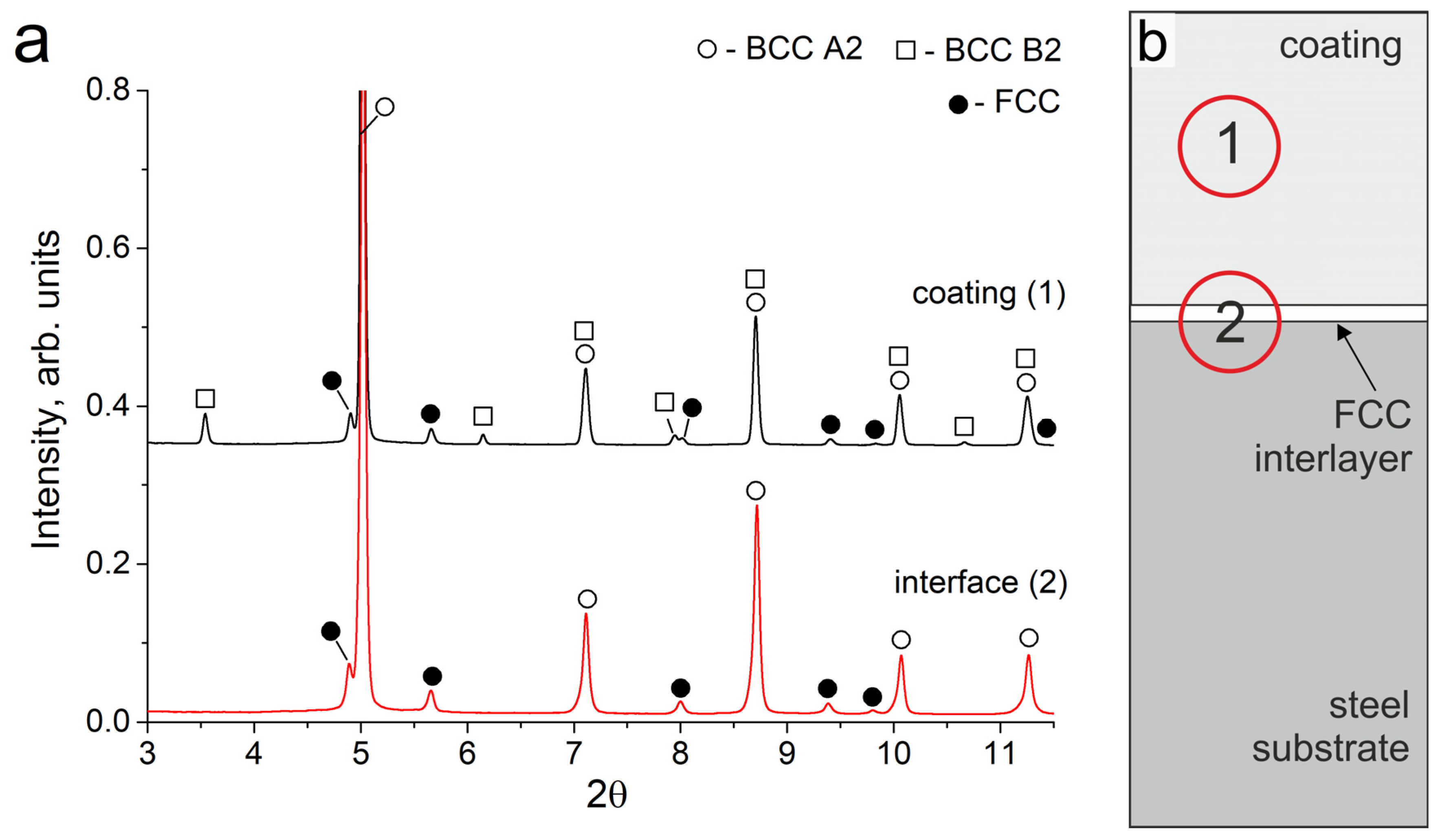
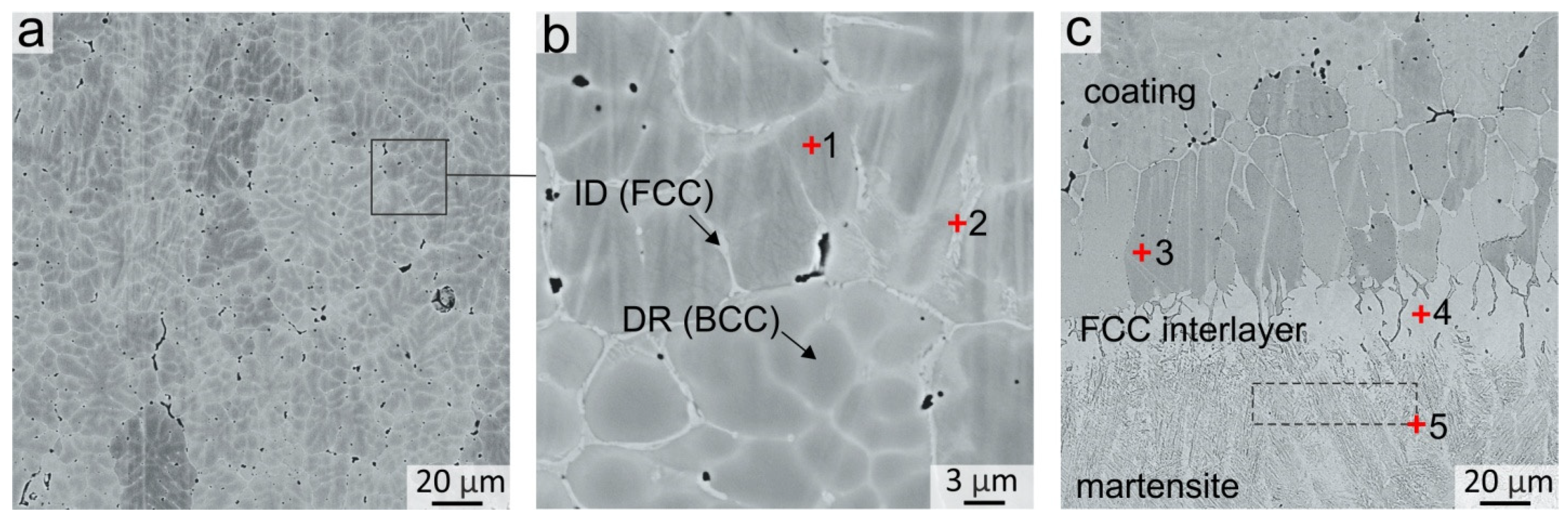
3.1. Structure of the Coatings

As a result of the cladding, a coating of Al-Fe-Co-Cr-Ni high-entropy alloy about 700 μm in thickness was formed on the steel substrates. Synchrotron X-ray diffraction studies showed that the obtained coating consisted of bcc (A2), ordered bcc (B2), and disordered fcc (A1) phases (Figure 1a, pattern # 1). It should be noted that the intensity of fcc reflections is noticeably weaker than that of bcc, which indicates a smaller volume fraction of the fcc phase in the coating. The fcc phase in the sample had a disordered A1 structure. For the bcc phase, a reflection of the ordered B2 structure was observed. A mixture of disordered bcc (A2) and ordered bcc (B2) structures forms as a result of spinodal decomposition, which is often noted in studies devoted to the HEAs of the Al-Fe-Co-Cr-Ni system [1,24,25,26].
The total element content of the coating is presented in Table 3. EDX-analysis showed that ~13 at. % of Fe in relation to other cladding elements dissolved in the melt pool; the composition of the coating corresponded to the non-equiatomic alloy Al21Co22Cr22Fe13Ni22. In the Al-Fe-Co-Cr-Ni system, the equiatomic alloy consists of BCC + fcc phases. The reduced Fe content in the obtained coating compared to the equiatomic alloy contributes to the decrease in the fraction of the fcc phase, which is noticeable in the structures of the obtained coating. It is known that the ratio of the bcc and fcc phases depends on the valence electron concentration (VEC) [27,28]. The VEC = 7.15 calculated for the obtained composition is slightly less than the VEC = 7.20 for the equiatomic AlCoCrFeNi alloy. Both of these values correspond to the VEC range of a two-phase bcc + fcc AlCoCrFeNi alloy. However, the VEC value for Al21Co22Cr22Fe13Ni22 is closer to the range of a single-phase bcc; thus, the phase ratio in this sample shifts towards the predominance of the bcc phase.
A typical dendritic structure was observed in the coating after crystallization. The dendritic bodies consisted of the bcc phase, whereas the fcc phase was predominantly distributed in the interdendritic spaces in the shape of discontinuous thin interlayers with a thickness not exceeding 2 μm (Figure 2a,b). The EDX analysis results of local dendritic and interdendritic zones are presented in Table 3. It follows that the bcc phase was enriched in Al and Ni, while the fcc phase was enriched in Fe and Cr (EDX point # 1 and 2, Figure 2b). Such a dendritic structure and elements distribution in bcc and fcc phases is typical for as-cast Al-Co-Cr-Fe-Ni alloys [29,30,31]. A concentration gradient was observed in bcc dendritic grains, in which the content of Cr and Fe increased and the content of Al and Ni decreased when further from the middle of the dendritic branches and closer to their boundaries. Co was distributed over the structure of the coating quite uniformly.
The structure of the samples near the “coating-substrate” interface (Figure 2c) differs significantly from that of the main coating zone because, closer to the substrate, the concentration of Fe increased significantly up to 65–85 at. %. Therefore, the tendency of the alloy to form the bcc phase decreased when moving towards the substrate. Joint analysis of SXRD (Figure 1a, pattern # 2), SEM and EDX results showed that a continuous layer of fcc grains was formed at the “coating-substrate” interface. The fcc layer contained approximately 63 at. % of Fe and other alloying elements of the coating in relative fractions corresponding to their initial ratio in the powder mixture (EDX point # 4, Figure 2c and Table 3). The thickness of the fcc interlayer varied from 20 to 40 μm. Due to directional heat removal, the fcc grains at the “coating-substrate” interface had an elongated shape and were oriented predominantly perpendicular to the substrate.
Under the fcc interlayer, a 20–40 µm thick interlayer of needle martensitic structure was formed. A large temperature gradient between the substrate and the melted pool contributed to a high cooling rate in this zone. Furthermore, the Fe content in this zone is ~86 at. % (EDX area # 5 in Figure 2c and Table 3). Thus, the formation of the martensitic phase was caused by a high cooling rate and a decrease in the critical cooling rate of the matrensitic transformation due to alloying with Co, Cr and Ni.
The area analyzed by the SXRD method was 200 µm in diameter; therefore, bcc grains from the bottom part of the coating were within this area. However, no reflections of the B2 superstructure were observed in this zone. It can be concluded that the bcc phase in the lower part of the coating consists mainly of a disordered bcc phase with an A2 structure. This feature was associated with a high concentration of Fe and a reduced concentration of other elements in the bottom part of the coating compared to the dendritic zone (EDX point # 3, Figure 2c and Table 3). Al and Ni are the elements that usually form an ordered B2 superlattice in the bcc. The reduced concentration of Al and Ni in the bottom part of the coating promoted the formation of bcc grains that predominantly had a disordered bcc A2 structure.
According to the EDX analysis data, an increased content of Si (0.51–0.68 at. %) and Mn (0.35–0.51 at. %) was observed in the bottom part of the coating (EDX points # 3, 4, 5, Figure 3c and Table 3). These elements were transferred into the coating from the steel substrate.
At the same time, in the main material of the coating, only the presence of Si was recorded (EDX points # 1, 2, Figure 2c and Table 3). It should be noted that the Si concentration was higher in the interdendritic fcc regions than in the bcc denditic grains. This is probably because the fcc phase crystallized at a lower temperature than the bcc dendrites, and the diffusion Si from the substrate occurred mostly along the interdendritic regions.

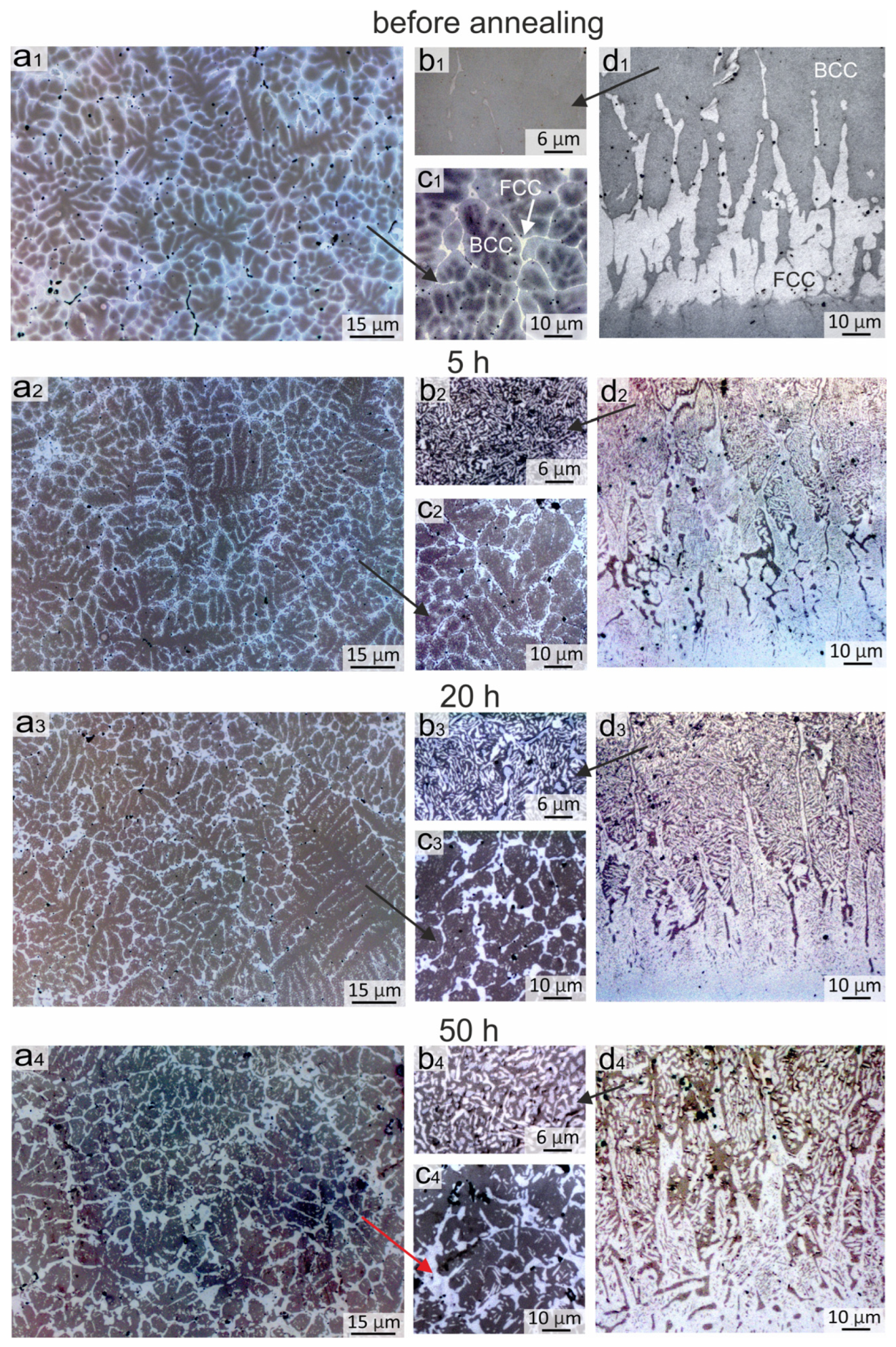
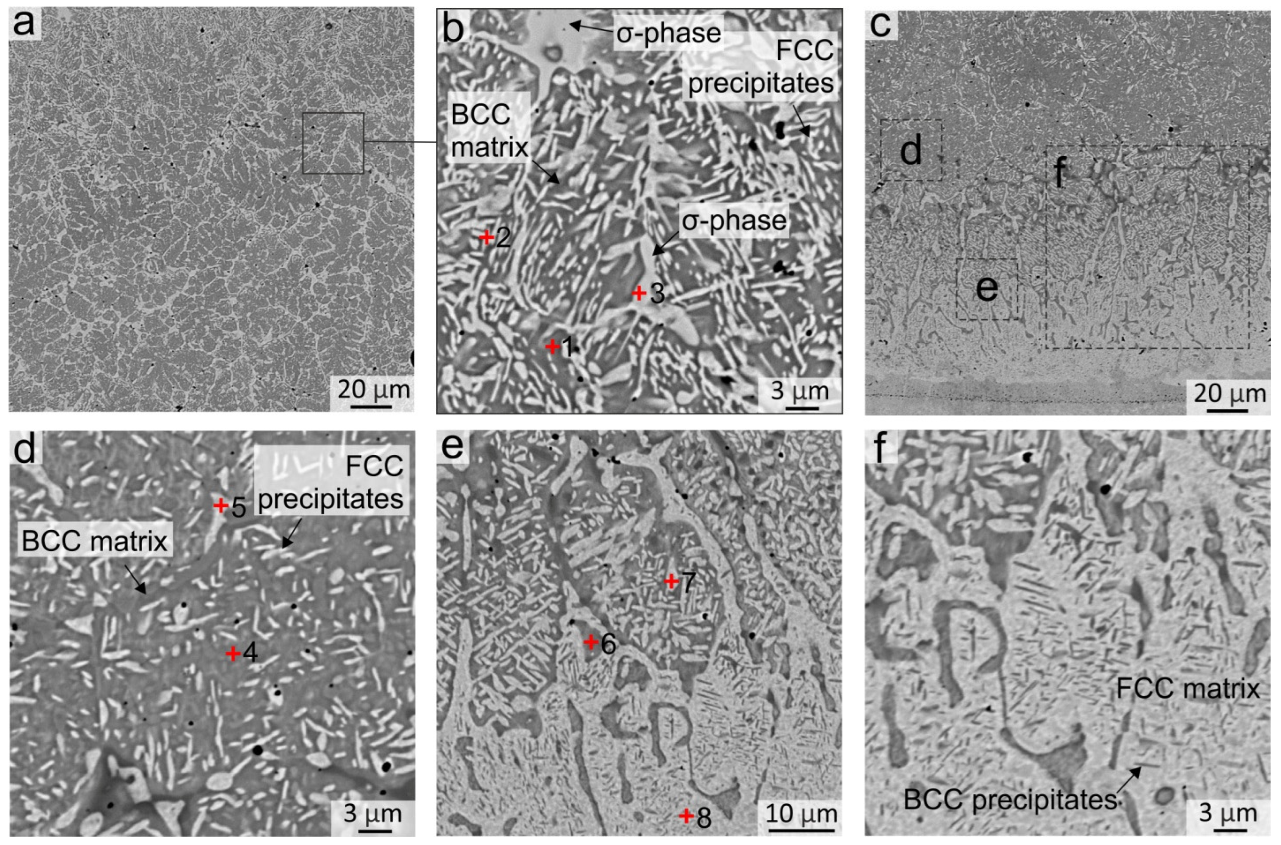
3.2. Evolution of the Coating Structure during Annealing at 900 °C

Al-Co-Cr-Fe-Ni alloys are promising candidates for high-temperature applications. However, the structure of the coatings can change due to long-term high-temperature exposure. As was mentioned before, the structural evolution were studied in detail only for equiatomic or AlxCoCrFeNi compositions, while the evolution in the structure of the Fe-depleted composition of the Al-Co-Cr-Fe-Ni alloy can have differences and its own features. To understand the structural transformations occurring in the coatings of the Al-Co-Cr-Fe-Ni system with reduced Fe content during operation at elevated temperatures, the obtained Al21Co22Cr22Fe13Ni22 samples were annealed at 900 °C for 5, 20 and 50 h.
The evolution of the structure in the samples is presented in the metallographic images in Figure 3. Figure 3(a1–a4) shows changes in the top and middle part of the coating, Figure 3(c1–c4) illustrates its scaled structure, Figure 3(b1–b4) corresponds to the bottom part of the coating, and Figure 3(d1–d4) demonstrates the changes in the “coating-substrate” interface. The structure of the samples annealed for 50 h was also studied by SEM.

3.2.1. Structural Transformations Occurring in the Top and Middle Part of the Coating

As shown above, the structure of the coating after cladding consisted of dendrites and interdendritic layers. The dendrites included the bcc phase, the interdendritic layers were mainly the fcc phase, and the concentration gradient in bcc grains was characterized by increasing Cr and Fe content and decreasing Al and Ni content closer to the interdendritic regions. The metallographic images of the sample are shown for convenient comparison with the annealed samples in Figure 3(a1,c1).
After 5 h of annealing at 900 °C, the concentration gradient between the dendrites and the interdendritic region disappears, and fcc phase precipitations begin to appear in these areas. In addition, the sizes of the interdendritic fcc phase zones increased (Figure 3(c2)). After 20 h of annealing, the nanosized fcc precipitations grew and became more visually distinguishable in metallographic images (Figure 3(c3)). During further annealing, the inclusions grew in length; their average thickness after 50 h of annealing was ~0.5 μm and the length varied from 1 to 5 μm (Figure 3(c4) and Figure 4b). The size of the precipitations after 50 h of annealing became sufficiently largefor their composition to be evaluated by EDX analysis and compared with the SXRD results. EDX-analysis showed that these inclusions differed from the matrix by the increased content of Cr and Fe and the decreased content of Ni and Al (EDX zones 1 and 2, Figure 4b and Table 4). The increase in the fcc volume fraction was also evidenced by the increase in intensity of fcc reflections in the SXRD patterns presented in Figure 5a (pattern # 1).
EDX analysis of the sample after 50 h of annealing showed that the element composition of the particles precipitated in the interdendritic regions is different. Some of them corresponded to the fcc phase (EDX point # 2 in Figure 4b and Table 4) and others had the composition which is typical of the σ-phase (EDX point # 3 in Figure 4b and Table 4). The formation of the σ-phase after 50 h of annealing was observed on SXRD patterns taken from the middle part of the coating (Figure 5a, pattern # 1). Large σ-phase precipitates have a rounded shape and are predominantly formed in the regions of former fcc grains at the boundary between several bcc grains, where Cr and Fe concentrations were initially higher.
When we analyze the transformations that occurred during annealing in the main part of the coating, it should be noted that according to the equilibrium phase diagrams the σ-phase is stable in the Al-Co-Cr-Fe-Ni system [32,33,34]. The phase equilibria calculations for the Al–Co–Cr–Fe–Ni system predicted the formation of the A1+A2+B2+σ-phase mixture in a wide concentration range from 10 to 20 at. % of Al [26]. Wang et al. [35] confirmed the phase transition of the A2+B2 bcc structure to the fcc+σ+B2 structure in Al0.9–Al1.2 AlxCoCrFeNi alloys by differential scanning calorimetry. Strumza et al. [36] found that a fcc phase started to precipitate from the B2 bcc matrix at ~590 °C and the high-energy interphase at the fcc/bcc boundary led to the σ-phase precipitation.
After electron-beam cladding, the structure of the coating is in a non-equilibrium state due to rapid heat removal from the melt pool towards the massive steel substrate. Furthermore, the dendritic liquation of the elements occurred during crystallization. When annealing, the alloy decomposed into a matrix with an increased Al and Ni content, and precipitations with higher Fe and Cr content. Therefore, during the annealing of Al-Co-Cr-Fe-Ni HEAs, the fcc and σ-phase precipitates as a result of homogenization.
The best-known studies on fcc and σ-phase precipitation during annealing are related to the equiatomic AlCoCrFeNi and AlxCoCrFeNi alloy. In the present research, the amount of Fe was smaller. Furthermore, the annealing regimes in most analyzed works are different, which makes comparison with other works complicated. Furthermore, some researche with close regimes of annealing can be compared with the present study. For instance, in the investigation of the AlCoCrFeNi alloy after 18 h of annealing at 900 °C, Strumza et al. [36] revealed the appearance of elongated fcc particles and rounded σ-phase particles, where the fcc and σ-phase were predominantly concentrated in the former interdendritic areas, and fine fcc precipitations were observed in the center of the former dendrites. However, the number and size of precipitates in the equiatomic alloy in [36] were noticeably larger than in the present work because of the higher concentration of Fe. According to the calculated data in [31], a decrease in the amount of Fe in the AlCoCrFeNi leads to an increase in the B2 bcc and a decrease in the fcc volume fraction.

3.2.2. Structural Changes Occurring at the Bottom of the Coating

In the bottom part of the coating, significant changes occurred in the bcc grains already after 5 h of annealing, in which many fcc labyrinth-like particles precipitated (Figure 3(b2)). This was due to a higher Fe concentration in the bottom part of the coating in comparison to the upper and central regions (EDX spectra # 4–7 in Figure 4d,e and Table 4). With an increase in the annealing time, the precipitates grew in size and after 50 h of annealing reached ~5 μm (Figure 3(b4)). Thus, the Fe-enriched bcc phase was decomposed into the bcc and fcc, in which the bcc matrix became depleted in the Fe (EDX spectra # 4 and 5 in Figure 4d, EDX spectra # 6 and 7 in Figure 4e and Table 4). In addition to fcc particles, inclusions of the σ-phase were formed locally in the bottom part of the coating. However, the Cr content in the bottom part of the coating was not sufficient for the formation of a great amount of the σ-phase; therefore, the presence of the σ-phase was not detected in the SXRD patterns. A similar structure was observed in [36] after 18 h of annealing at 900 °C in the regions, where the Fe concentration was higher.

3.2.3. Structural Transformations Occurring at the “Coating-Substrate” Interface

Figure 3(d1–d4) shows the evolution of the structure at the “coating-substrate” interface during annealing. After 5 h of annealing at 900 °C, a clear boundary between the substrate and the fcc interlayer was blurred due to the interdiffusion at elevated temperatures (Figure 3(d1,d2)). Fine nanosized inclusions appeared in fcc grains in the annealed structure. After 20 h of annealing, fine inclusions in the fcc interlayer grew and became more clearly visible in metallographic images (Figure 3(d3,d4)). The SEM images demonstrate that after 50 h of annealing, precipitations looked like thin plates up to 3 µm long with a strict ordered orientation in the matrix of fcc grains (Figure 4e,f). Because the particles were much smaller than the area of the EDX specter, it was not possible to estimate their elemental composition. However, the SEM images taken in the BSE mode indirectly indicated that the darker lamellar inclusions contain significantly more Al. The published works by other researchers give reason to believe that these particles were the B2 phase precipitations. According to the thermodynamic calculations of the AlxCoCrFeNi phase diagrams [32,33,34], the fcc-phase field on the diagram increases with the increasing temperature despite the fact that Al plays a contradictory role as a strong bcc stabilizer. With a decrease in the temperature below 1250 °C, the amount of Al in the fcc-solid solution reduces and the Ni-Al-enriched B2 phase precipitates.
For instance, it was shown in [12] that lamellar B2 bcc particles precipitated in the fcc phase during the annealing at 800 and 900 °C in an Al–Co–Cr–Fe–Ni alloy with a low Cr content. In [37,38,39], calculations in CALPHAD showed that Al–Co–Cr–Fe–Ni fcc alloys with a lack of Al tend to form B2 phase particles at temperatures above 580 °C. In [40], the above calculations were confirmed experimentally by TEM, where the appearance of B2 particles in the fcc matrix of the Al0.3CoCrFeNi alloy at 700 °C was observed. In [41], Gwalani et al. also detected B2 particles by TEM in the samples annealed at temperatures above 800 °C. In [38], B2 particles were precipitated after 5 h of homogenization at 1250 °C. In all these works, B2 particles were precipitated in the fcc of Al–Co–Cr–Fe–Ni HEAs mainly in the shape of nanosized plates.
It should be noted that the SXRD pattern recorded before annealing showed no peaks of the B2 structure at the “coating-substrate” interface. However, after 50 h of annealing, the SXRD patterns showed weak B2 reflections (scaled area in Figure 5a, pattern # 2). These reflections could belong both to B2 particles that appeared in the fcc interlayer, and to B2 particles above the fcc interlayer, where the decomposition into Al, Ni-rich and Fe, Cr-rich zones occurred in the former bcc grains.

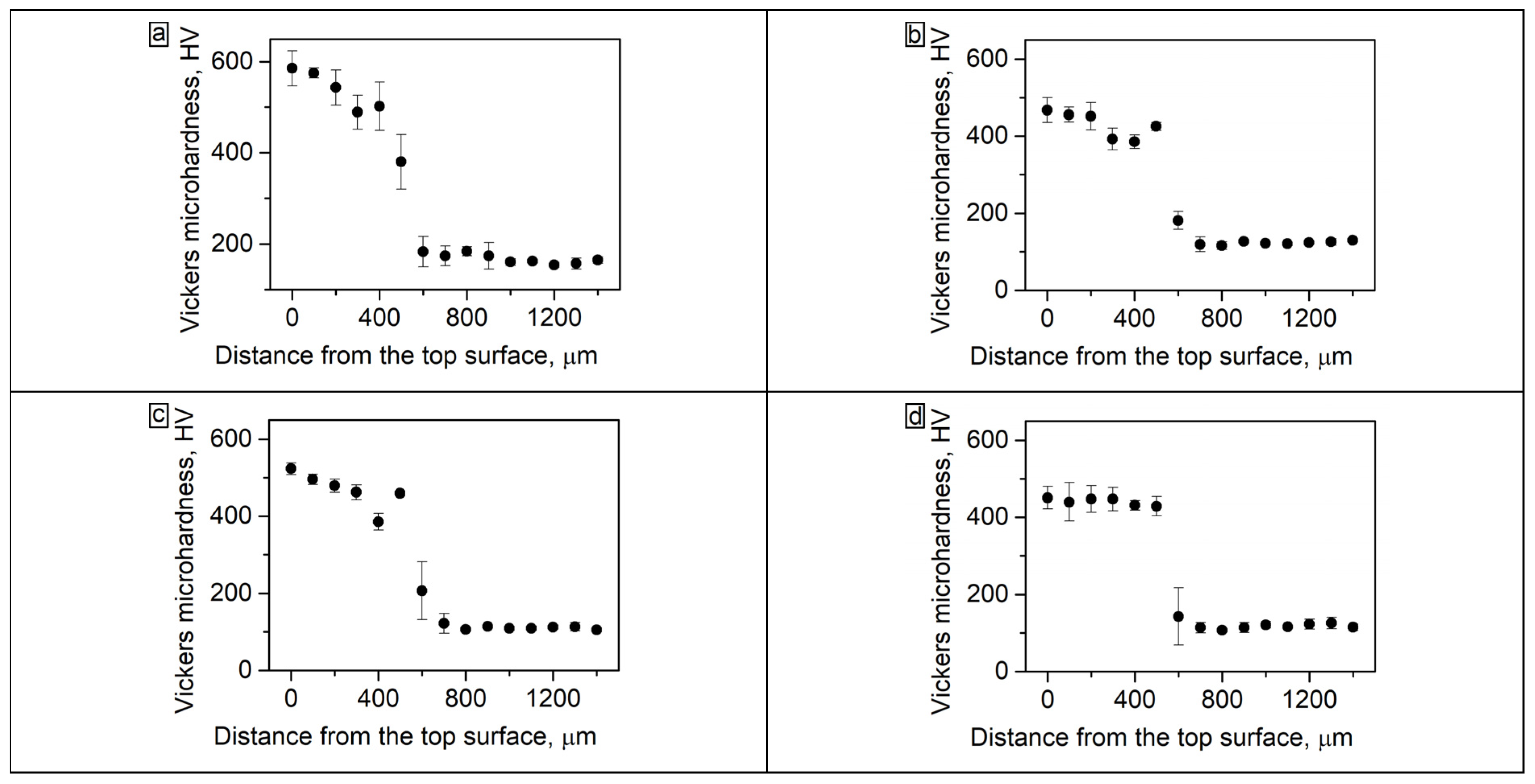
3.3. Microhardness of the Coating before and after Annealing

The microhardness test results after fabrication of the coatings and after annealing during 5, 20 and 50 h are shown in Figure 6. The average microhardness of the coating before annealing was 563 HV (Figure 6a). The fcc interlayer at the “coating-substrate” interface had a lower hardness; therefore, the graphs show a gradual decrease in hardness values when moving towards the substrate.
The precipitation of fcc particles and σ-phases in coating after 50 h of annealing promoted a decrease in microhardness to 441 HV (Figure 6d). The microhardness of the fcc interlayer after annealing, on the contrary, increased due to the precipitation of fine B2 particles. Thus, after 50 h of annealing, the microhardness level along the depth of the coating became more uniform.
A sharp drop in the microhardness pattern in the lower part of the coating after 5 and 20 h of annealing (Figure 6b,c, at ~350–400 µm from the top surface) should be noted. As was shown in the metallographic images, after 5 h of annealing at 900 °C a large amount of the fcc phase was precipitated in the bcc grains in the bottom part of the coating because of the high concentration of Fe at this distance. That was a reason for a local decrease in microhardness in these zones.
In the fcc interlayer, which is located under the above-mentioned Fe-rich zone at ~450 µm from the top surface, B2 particles were precipitated, which contributed to an increase in the fcc microhardness. Therefore, on the graphs corresponding to 5 and 20 h of annealing, a “tooth” was observed corresponding to the fcc interlayer hardened by B2 particles. However, after 50 h of annealing the microhardness of the main part of the coating and the fcc interlayer became approximately the same.

3.4. Oxidation of Coatings at 900 °C during 50 h

3.4.1. Composition of Oxide Films

Figure 7 shows maps of element distribution in the oxide layer, which formed after the oxidation of coatings in an air atmosphere for 50 h at 900 °C. The total thickness of the oxide film was approximately 12 μm. The mass gain after 50 h of oxidation was 0.6 mg/cm2. There were no publications found by other researchers on oxidation of the same composition under the same conditions, but the results were comparable to the oxidation behavior of the Al-Co-Cr-Cr-Ni HEAs [6,7,9,10]. In the cross-section of the oxide films, two clearly distinguishable sublayers can be seen: an upper sublayer with Fe, Co, and higher Cr content on top, and a lower sublayer containing mainly Al. The phase composition of oxide films after high-temperature oxidation of Al-Co-Cr-Fr-Ni alloys was studied in detail earlier [6,7,8,9,10,11]. As a rule, Cr2O3 oxide grows in the upper layer and Al2O3 forms in the lower sublayer.
According to EDX analysis, 5–6 at. % of Co and Fe were present in the upper sublayer of the oxide film; these elements tend to form spinels of the “MeMe2O4 type during oxidation of Al-Co-Cr-Cr-Ni alloys. EDX maps showed a higher concentration of Fe, Cr and Co in the bottom part of the sublayer; it can therefore be assumed that more spinel inclusions in the oxide layer grew in this region, and Cr2O3 mostly was formed on the top. According to the literature analysis, the composition of spinels can differ depending on the oxidation regimes and alloy composition. Thus, Butler et al. revealed the presence of a NiCr2O4 spinel after oxidation at 1050 °C of Al10Cr22.5Co22.5Ni22.5Fe22.5 [8] and Al15(CoCrFeNi)85 [7] alloys. Garg et al. [10] found CoFe2O4, FeCr2O4 and CoFe2O4 spinels after 100 h oxidation of an equiatomic AlCoCrFeNi alloy at 850 °C and 950 °C, and FeCr2O4, CoCr2O4 and FeCo2O4 spinels after 100 h oxidation at 1050 °C. Dąbrowa et al. [11] detected spinel reflections of the Fd-3m space group on X-ray diffraction patterns. In [6], the formation of a NiCr2O4 spinel was discovered using TEM after the oxidation of the AlCoCrFeNi alloy at 1050 °C for 50 h.
The absence of Ni should be noted in the composition of oxide films. This feature could be explained by the following. According to literature data, the main mechanism of growth of the outer Cr2O3 film was an active diffusion of Cr cations along the grain boundaries [10]. EDX analysis revealed that after annealing at 900 °C, Cr, Fe and Co were mainly concentrated at the grain boundaries, while Ni and Al were predominantly located in the bodies of the grains. The results obtained are in agreement with the above-described observations of other researchers, in which Ni-containing spinels were formed only at oxidation temperatures above 900 °C. The sublayer Al2O3 was formed due to the internal diffusion of O2− and external diffusion of Al3+ through the grain bodies of the coating. The same mechanism of the Al2O3 formation during oxidation is usually observed in B2 alloys based on NiAl [42,43,44]. According to EDX analysis, the Al-rich oxide sublayer practically did not contain spinel-forming elements. The obtained results were in agreement with the scheme of oxide layer growth on the equiatomic AlCoCrFeNi presented in [10], in which spinels were formed only in the upper Cr2O3 sublayer.
Under the Al2O3 sublayer, a zone of the alloy ~20 µm in thickness containing a high concentration of Co, Cr, and Fe was formed as a result of the outer diffusion of elements along the drain boundaries. In this zone, dark inclusions with increased local concentration of Al and N and O were found. According to [7,8,10,11], these inclusions were internal oxides of Al2O3 and nitrides AlN, which appeared due to the inner diffusion of oxygen and nitrogen and outer diffusion of Al.

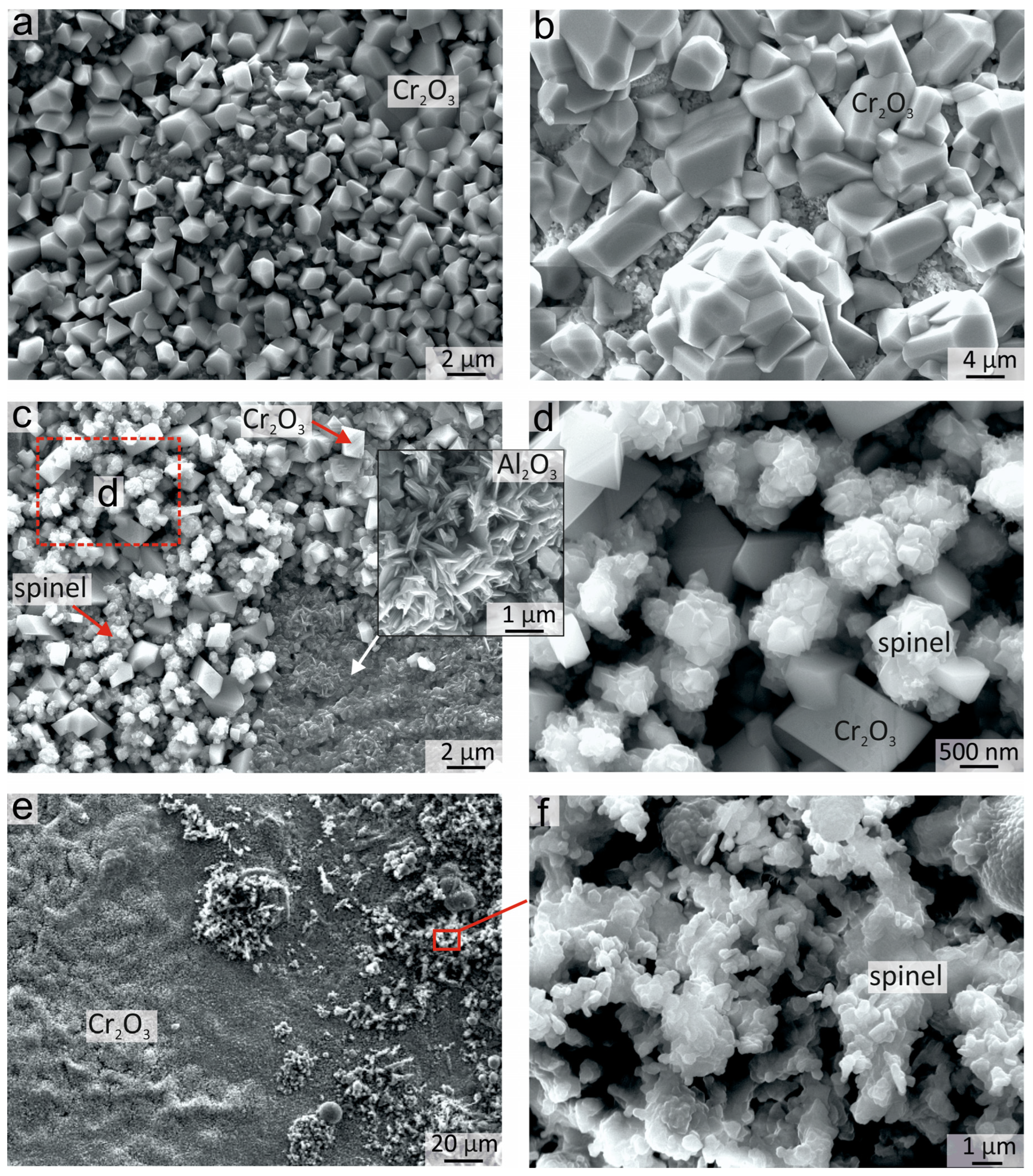
3.4.2. Surface Morphology of Oxide Films

In most works published to date on the oxidation of Al-Co-Cr-Fe-Ni HEAs, the observations of the surface morphology of oxidized coatings were quite poor. For more detailed consideration of this issue, the oxidized surface of the samples was studied by high-resolution SEM.
The surface morphology of the sample after oxidation for 50 h at 900 °C is shown in Figure 8. The morphology of the oxidized surface was not uniform, which was associated with the heterogeneous elemental and phase composition of coatings before as well as after annealing. The great surface area was occupied by rhomboid Cr2O3 crystals. This shape of crystals is typical for Cr2O3 formed after the oxidation of Al-Co-Cr-Fe-Ni HEAs [8,10]. The crystal sizes varied from 0.5 to 5 μm. Zones with both smaller (Figure 8a) and larger (Figure 8b) crystals could be observed on the top of the surface. The suggestion could be made that the regions with larger crystals correspond to areas with a thicker Cr2O3 oxide film, which started to form in the early stages of annealing in the Cr-rich areas of the coating, and further grew in size during the whole oxidation period.
Between the Cr2O3 crystals, the “rose-shaped” crystals can be seen on some parts of the surface (Figure 8c,d). Such morphology is typical for spinel crystals. A mixture of Cr2O3 and spinel crystals can also be observed in the lower part of the Cr2O3 layer when the upper part of the Cr2O3 oxide film is exfoliated. The formation of spinels predominantly in the lower part of Cr2O3 was due to higher Fe and Co content in this area of the oxide film. In some parts of the sample, the whole thickness of the Cr2O3 layer peeled off and exposed the needle-shaped sublayer of Al2O3 crystals (Figure 8c). Furthermore, the oxide film containing Cr2O3 and spinel crystals was also formed in the fcc area of the coating where the concentration of Fe and Co was higher.
Clusters of spinel crystals with rounded edges of the plates could also be observed on the surface of the Cr2O3 oxide film (Figure 8e,f). The spinels with different morphologies in Figure 8d,f probably had different compositions, but it was not possible to determine the composition precisely by EDX due to the very small size of the crystals.

4. Conclusions

Bcc (A2 + B2) + fcc (A1) high-entropy coating Al21Co22Cr22Fe13Ni22 with the fcc interlayer at the “coating-substrate” interface were formed on a low-carbon steel substrate using non-vacuum electron-beam cladding of powders. After annealing at 900 °C, elongated fcc particles and rounded particles of the σ-phase precipitated in the coating. In the fcc interlayer, annealing promoted the precipitation of the B2 bcc nanoscale plates. The precipitation of the fcc and σ-phase led to a decrease in the microhardness of the coating from 563 HV to 441 HV; however, the microhardness level over the cross-section of the coating became more uniform.
The oxidation of the coatings in the air at 900 °C during 50 h promoted the formation of oxide films consisting of two sublayers. The top sublayer contained large rhomboid crystals of Cr2O3 and spinel crystals of a branched rose-like morphology. The lower sublayer mainly contained needle-like crystals of Al2O3.
Due to high corrosion resistance, such alloys could replace more brittle intermetallic compounds as protective coatings for Fe-based alloys. For further investigations, the effect of composition on mechanical properties of the coatings should be considered. In addition, when cladding the powder mixtures with different compositions, the amount of Fe transferred from the substrate can vary, which is also an interesting issue for future studies.

Author Contributions

Conceptualization, T.O.; methodology, A.R., E.D. and I.C.; investigation, K.E., Y.M., A.R., P.R., A.Y., I.B. and T.O.; writing—original draft preparation, T.O. and I.B.; writing—review and editing, T.O. and I.B.; supervision, T.O.; project administration, T.O.; funding acquisition, T.O. All authors have read and agreed to the published version of the manuscript.

Funding

This research was supported by a grant from the Russian Science Foundation, No. 22-23-20192, https://rscf.ru/project/22-23-20192/, and grant No. p-31 from the Government of the Novosibirsk Region.

Data Availability Statement

The data that support the findings of this study are available from the corresponding author upon reasonable request.

Acknowledgments

Research was conducted at the core “Structure, mechanical and physical properties of materials” facility of Novosibirsk State Technical University (agreement with the Ministry of Science and Higher Education of the Russian Federation, No. 13.CKP.21.0034, 075-15-2021-698).

Conflicts of Interest

The authors declare no conflict of interest.

References

  1. Yeh, J.; Chen, S.; Lin, S.; Gan, J.; Chin, T.; Shun, T.; Tsau, C.; Chang, S. Nanostructured High-entropy Alloys with Multiple Principal Elements: Novel Alloy Design Concepts and Outcomes. Adv. Eng. Mater. 2004, 6, 299–303. [Google Scholar] [CrossRef]
  2. Wang, S.; Ren, C.; Tian, H.; Yu, J.; Sun, M. MoS2/ZnO van Der Waals Heterostructure as a High-Efficiency Water Splitting Photocatalyst: A First-Principles Study. Phys. Chem. Chem. Phys. 2018, 20, 13394–13399. [Google Scholar] [CrossRef] [PubMed]
  3. Wang, S.; Tian, H.; Ren, C.; Yu, J.; Sun, M. Electronic and Optical Properties of Heterostructures Based on Transition Metal Dichalcogenides and Graphene-like Zinc Oxide. Sci. Rep. 2018, 8, 12009. [Google Scholar] [CrossRef] [PubMed]
  4. Gautam, S.; Agrawal, H.; Thakur, M.; Akbari, A.; Sharda, H.; Kaur, R.; Amini, M. Metal Oxides and Metal Organic Frameworks for the Photocatalytic Degradation: A Review. J. Environ. Chem. Eng. 2020, 8, 103726. [Google Scholar] [CrossRef]
  5. Grilli, M.L. Metal Oxides. Metals 2020, 10, 820. [Google Scholar] [CrossRef]
  6. Butler, T.M.; Weaver, M.L. Oxidation Behavior of Arc Melted AlCoCrFeNi Multi-Component High-Entropy Alloys. J. Alloys Compd. 2016, 674, 229–244. [Google Scholar] [CrossRef]
  7. Butler, T.M.; Weaver, M.L. Influence of Annealing on the Microstructures and Oxidation Behaviors of Al8(CoCrFeNi)92, Al15(CoCrFeNi)85, and Al30(CoCrFeNi)70 High-Entropy Alloys. Metals 2016, 6, 222. [Google Scholar] [CrossRef]
  8. Butler, T.M.; Alfano, J.P.; Martens, R.L.; Weaver, M.L. High-Temperature Oxidation Behavior of Al-Co-Cr-Ni-(Fe or Si) Multicomponent High-Entropy Alloys. Jom 2015, 67, 246–259. [Google Scholar] [CrossRef]
  9. Veselkov, S.; Samoilova, O.; Shaburova, N.; Trofimov, E. High-Temperature Oxidation of High-Entropic Alloys: A Review. Materials 2021, 14, 595. [Google Scholar] [CrossRef]
  10. Garg, M.; Grewal, H.S.; Sharma, R.K.; Arora, H.S. Improving the High Temperature Oxidation Resistance of High Entropy Alloy by Surface Modification. Corros. Rev. 2023, 41, 39–56. [Google Scholar] [CrossRef]
  11. Dąbrowa, J.; Cieślak, G.; Stygar, M.; Zajusz, M.; Jawańska, M.; Gil, A.; Jedliński, J.; Mroczka, K.; Matsuda, K.; Kulik, T.; et al. Oxidation Behavior of Alx(CoCrFeNi)100−x High-Entropy Alloys Under Thermal-Cycling Conditions. Oxid. Met. 2021, 96, 307–321. [Google Scholar] [CrossRef]
  12. Shen, Q.; Kong, X.; Chen, X. Significant Transitions of Microstructure and Mechanical Properties in Additively Manufactured Al–Co–Cr–Fe–Ni High-Entropy Alloy under Heat Treatment. Mater. Sci. Eng. A 2021, 815, 141257. [Google Scholar] [CrossRef]
  13. Niu, S.; Kou, H.; Guo, T.; Zhang, Y.; Wang, J.; Li, J. Strengthening of Nanoprecipitations in an Annealed Al0.5CoCrFeNi High Entropy Alloy. Mater. Sci. Eng. A 2016, 671, 82–86. [Google Scholar] [CrossRef]
  14. Chen, L.; Bobzin, K.; Zhou, Z.; Zhao, L.; Öte, M.; Königstein, T.; Tan, Z.; He, D. Effect of Heat Treatment on the Phase Composition, Microstructure and Mechanical Properties of Al0.6 Crfeconi and Al0.6 Crfeconisi0.3 High-Entropy Alloys. Metals 2018, 8, 974. [Google Scholar] [CrossRef]
  15. Butler, T.M.; Weaver, M.L. Investigation of the Phase Stabilities in AlNiCoCrFe High Entropy Alloys. J. Alloys Compd. 2017, 691, 119–129. [Google Scholar] [CrossRef]
  16. Zhang, C.; Zhang, F.; Diao, H.; Gao, M.C.; Tang, Z.; Poplawsky, J.D.; Liaw, P.K. Understanding Phase Stability of Al-Co-Cr-Fe-Ni High Entropy Alloys. Mater. Des. 2016, 109, 425–433. [Google Scholar] [CrossRef]
  17. Munitz, A.; Salhov, S.; Hayun, S.; Frage, N. Heat Treatment Impacts the Micro-Structure and Mechanical Properties of AlCoCrFeNi High Entropy Alloy. J. Alloys Compd. 2016, 683, 221–230. [Google Scholar] [CrossRef]
  18. Wang, R.; Zhang, K.; Davies, C.; Wu, X. Evolution of Microstructure, Mechanical and Corrosion Properties of AlCoCrFeNi High-Entropy Alloy Prepared by Direct Laser Fabrication. J. Alloys Compd. 2017, 694, 971–981. [Google Scholar] [CrossRef]
  19. Zimogliadova, T.A.; Bataev, A.A.; Lazurenko, D.V.; Bataev, I.A.; Bataev, V.A.; Golkovskii, M.G.; Saage, H.; Ogneva, T.S.; Ruktuev, A.A. Structural Characterization of Layers Fabricated by Non-Vacuum Electron Beam Cladding of Ni-Cr-Si-B Self-Fluxing Alloy with Additions of Niobium and Boron. Mater. Today Commun. 2022, 33, 104363. [Google Scholar] [CrossRef]
  20. Ruktuev, A.A.; Golkovski, M.G.; Lazurenko, D.V.; Bataev, V.A.; Ivanov, I.V.; Thömmes, A.; Bataev, I.A. TiTaNb Clads Produced by Electron Beam Surface Alloying in Regular Air at Atmospheric Pressure: Fabrication, Structure, and Properties. Mater. Charact. 2021, 179, 111375. [Google Scholar] [CrossRef]
  21. Ruktuev, A.A.; Lazurenko, D.V.; Ogneva, T.S.; Kuzmin, R.I.; Golkovski, M.G.; Bataev, I.A. Structure and Oxidation Behavior of CoCrFeNiX (Where X Is Al, Cu, or Mn) Coatings Obtained by Electron Beam Cladding in Air Atmosphere. Surf. Coatings Technol. 2022, 448, 128921. [Google Scholar] [CrossRef]
  22. Ogneva, T.; Ruktuev, A.; Girsh, A. Non-Vacuum Electron Beam Cladding of Ti-Ni-Al Intermetallics on Titanium Alloy. Mater. Today Proc. 2019, 11, 191–196. [Google Scholar] [CrossRef]
  23. Ogneva, T.S.; Ruktuev, A.A.; Lazurenko, D.V.; Emurlaev, K.I.; Malyutina, Y.N.; Golkovsky, M.G.; Egoshin, K.D.; Bataev, I.A. Structure and Oxidation Behavior of NiAl-Based Coatings Produced by Non-Vacuum Electron Beam Cladding on Low-Carbon Steel. Metals 2022, 12, 1679. [Google Scholar] [CrossRef]
  24. Chen, R.; Xie, T.; Wu, B.; Weng, L.; Ali, H.; Yang, S.; Zhao, Y.; Zhao, P.; Zhang, C.; Cao, R.; et al. A General Approach to Simulate the Atom Distribution, Lattice Distortion, and Mechanical Properties of Multi-Principal Element Alloys Based on Site Preference: Using FCC_CoNiV and CoCrNi to Demonstrate and Compare. J. Alloys Compd. 2023, 935, 168016. [Google Scholar] [CrossRef]
  25. Silvello, A.; Torres Diaz, E.; Rúa Ramirez, E.; Garcia Cano, I. Microstructural, Mechanical and Wear Properties of Atmospheric Plasma-Sprayed and High-Velocity Oxy-Fuel AlCoCrFeNi Equiatomic High-Entropy Alloys (HEAs) Coatings. J. Therm. Spray Technol. 2023, 2023, 520. [Google Scholar] [CrossRef]
  26. Stryzhyboroda, O.; Witusiewicz, V.T.; Gein, S.; Röhrens, D.; Hecht, U. Phase Equilibria in the Al–Co–Cr–Fe–Ni High Entropy Alloy System: Thermodynamic Description and Experimental Study. Front. Mater. 2020, 7, 270. [Google Scholar] [CrossRef]
  27. Guo, S.; Ng, C.; Lu, J.; Liu, C.T. Effect of Valence Electron Concentration on Stability of Fcc or Bcc Phase in High Entropy Alloys. J. Appl. Phys. 2011, 109, 103505. [Google Scholar] [CrossRef]
  28. Tian, F.; Delczeg, L.; Chen, N.; Varga, L.K.; Shen, J.; Vitos, L. Structural Stability of NiCoFeCrAlx High-Entropy Alloy from Ab Initio Theory. Phys. Rev. B 2013, 88, 85128. [Google Scholar] [CrossRef]
  29. Ma, Y.; Jiang, B.; Li, C.; Wang, Q.; Dong, C.; Liaw, P.K.; Xu, F.; Sun, L. The BCC/B2 Morphologies in AlxNiCoFeCr High-Entropy Alloys. Metals 2017, 7, 57. [Google Scholar] [CrossRef]
  30. Yang, T.; Xia, S.; Liu, S.; Wang, C.; Liu, S.; Zhang, Y.; Xue, J.; Yan, S.; Wang, Y. Effects of AL Addition on Microstructure and Mechanical Properties of AlxCoCrFeNi High-Entropy Alloy. Mater. Sci. Eng. A 2015, 648, 15–22. [Google Scholar] [CrossRef]
  31. Zhang, G.J.; Tian, Q.W.; Yin, K.X.; Niu, S.Q.; Wu, M.H.; Wang, W.W.; Wang, Y.N.; Huang, J.C. Effect of Fe on Microstructure and Properties of AlCoCrFexNi (X = 1.5, 2.5) High Entropy Alloy Coatings Prepared by Laser Cladding. Intermetallics 2020, 119, 722. [Google Scholar] [CrossRef]
  32. Sistla, H.R.; Newkirk, J.W.; Frank Liou, F. Effect of Al/Ni Ratio, Heat Treatment on Phase Transformations and Microstructure of AlxFeCoCrNi2−x (X = 0.3, 1) High Entropy Alloys. Mater. Des. 2015, 81, 113–121. [Google Scholar] [CrossRef]
  33. Kuwabara, K.; Shiratori, H.; Fujieda, T.; Yamanaka, K.; Koizumi, Y.; Chiba, A. Mechanical and Corrosion Properties of AlCoCrFeNi High-Entropy Alloy Fabricated with Selective Electron Beam Melting. Addit. Manuf. 2018, 23, 264–271. [Google Scholar] [CrossRef]
  34. Ostrowska, M.; Riani, P.; Bocklund, B.; Liu, Z.-K.; Cacciamani, G. Thermodynamic Modeling of the Al-Co-Cr-Fe-Ni High Entropy Alloys Supported by Key Experiments. J. Alloys Compd. 2022, 897, 162722. [Google Scholar] [CrossRef]
  35. Wang, W.-R.; Wang, W.-L.; Yeh, J.-W. Phases, Microstructure and Mechanical Properties of AlxCoCrFeNi High-Entropy Alloys at Elevated Temperatures. J. Alloys Compd. 2014, 589, 143–152. [Google Scholar] [CrossRef]
  36. Strumza, E.; Hayun, S. Comprehensive Study of Phase Transitions in Equiatomic AlCoCrFeNi High-Entropy Alloy. J. Alloys Compd. 2021, 856, 220. [Google Scholar] [CrossRef]
  37. Liu, K.; Komarasamy, M.; Gwalani, B.; Shukla, S.; Mishra, R.S. Fatigue Behavior of Ultrafine Grained Triplex Al0.3CoCrFeNi High Entropy Alloy. Scr. Mater. 2019, 158, 116–120. [Google Scholar] [CrossRef]
  38. Hou, J.; Shi, X.; Qiao, J.; Zhang, Y.; Liaw, P.K.; Wu, Y. Ultrafine-Grained Dual Phase Al0.45CoCrFeNi High-Entropy Alloys. Mater. Des. 2019, 180, 910. [Google Scholar] [CrossRef]
  39. Chen, M.; Lan, L.; Shi, X.; Yang, H.; Zhang, M.; Qiao, J. The Tribological Properties of Al0.6CoCrFeNi High-Entropy Alloy with the σ Phase Precipitation at Elevated Temperature. J. Alloys Compd. 2019, 777, 180–189. [Google Scholar] [CrossRef]
  40. Gwalani, B.; Soni, V.; Lee, M.; Mantri, S.A.; Ren, Y.; Banerjee, R. Optimizing the Coupled Effects of Hall-Petch and Precipitation Strengthening in a Al0.3CoCrFeNi High Entropy Alloy. Mater. Des. 2017, 121, 254–260. [Google Scholar] [CrossRef]
  41. Gwalani, B.; Soni, V.; Choudhuri, D.; Lee, M.; Hwang, J.Y.; Nam, S.J.; Ryu, H.; Hong, S.H.; Banerjee, R. Stability of Ordered L12 and B2 Precipitates in Face Centered Cubic Based High Entropy Alloys—Al0.3CoFeCrNi and Al0.3CuFeCrNi2. Scr. Mater. 2016, 123, 130–134. [Google Scholar] [CrossRef]
  42. Brumm, M.W.; Grabke, H.J.; Wagemann, B. The Oxidation of NiAl-III. Internal and Intergranular Oxidation. Corros. Sci. 1994, 36, 37–53. [Google Scholar] [CrossRef]
  43. Pint, B.A.; Treska, M.; Hobbs, L.W. The Effect of Various Oxide Dispersions on the Phase Composition and Morphology of Al2O3 Scales Grown on β-NiAl. Oxid. Met. 1997, 47, 369. [Google Scholar] [CrossRef]
  44. Miracle, D.B.B. Overview No. 104 The Physical and Mechanical Properties of NiAl. Acta Metall. Mater. 1993, 41, 649–684. [Google Scholar] [CrossRef]
Figure 1. (a) SXRD patterns of the Al21Co22Cr22Fe13Ni22 coating and interface zones; (b) The schematic location of the analyzed zones (1) and (2) on the sample.
Metals 13 01689 g001
Figure 2. (a,b) Structure of the Al21Co22Cr22Fe13Ni22 coating obtained by non-vacuum electron beam cladding; (c) Structure at the coating–substrate interface. EDX analysis results of specters 1–5 are presented in Table 2.
Metals 13 01689 g002
Figure 3. Evolution of the structure in the Al21Co22Cr22Fe13Ni22 coating obtained by non-vacuum electron beam cladding before and after annealing at 900 °C during 5, 20 and 50 h (optical microscopy): (a1a4,c1c4) General structure of the coating; (b1b4) The bcc zone of the coating near the “coating-substrate” interface; (d1d4) The structure of the “coating-substrate” interface.
Metals 13 01689 g003
Figure 4. The structure of the Al21Co22Cr22Fe13Ni22 coating obtained by non-vacuum electron beam cladding after annealing at 900 °C during 50 h (a,b) Structure in the middle of the coating; (c,d) Structure in the bottom part of the coating; (e,f) Structure of the fcc interlayer between the coating and the substrate. EDX analysis results of specters 1–8 are presented in Table 4.
Metals 13 01689 g004
Figure 5. (a) SXRD patterns of the Al21Co22Cr22Fe13Ni22 coating (1) and interface zones (2) after annealing at 900 °C during 50 h; dashed lines limit the pattern zones scaled ×16 by vertical axe; (b) The schematic location of the analyzed zones (1) and (2) on the sample.
Metals 13 01689 g005
Figure 6. (a) The microhardness of the Al21Co22Cr22Fe13Ni22 coating on low-carbon steel in the cross-section: (a) as-cladded; (b) 5 h annealing; (c) 10 h annealing; (d) 50 h annealing.
Metals 13 01689 g006
Figure 7. Distribution of elements after oxidation of the Al21Co22Cr22Fe13Ni22 sample at 900 °C during 50 h. The composition of the points is presented in Table 5. EDX analysis results of specters 1–6 are presented in Table 5.
Metals 13 01689 g007
Figure 8. The morphology of the oxide films formed on the Al21Co22Cr22Fe13Ni22 coating after oxidation for 50 h 900 °C: (a) Cr2O3 small crystals; (b) Cr2O3 coarse crystals; (c) zones of Cr2O3, Al2O3 and spinel; (d) zone of joint growth of Cr2O3 and spinel crystals; (e) Cr2O3 and spinel on the top surface; (f) agglomerates of spinel crystals on the top surface.
Metals 13 01689 g008
Table 1. Elemental composition of the substrate and powder mixture used for surfacing.
ElementAl, at. %Co, at. %Cr, at. %Ni, at. %Fe, at. %C, at. %Si, at. %Mn, at. %
Substrate material--0.25-98.720.20.280.55
Powder mixture25252525----
Table 2. Parameters of the cladding process.
Mass of Powder Mixture *, gMass of Flux *, gBeam Current, мATable Velocity, mm/sMass of Powder Mixture per Unit Area **, g/cm2Energy Density, kJ/cm2
15.757.225150.450.47
* mass distributed over the entire area of the substrate 100 × 50 mm. ** amount of powder mixture (metal powder and flux) per 1 cm2 of substrate.
Table 3. Composition and corresponding phases of the as-cladded sample. The points of measurements are shown in Figure 2b,c.
Point # Al, at. %Cr, at. %Fe, at. %Co, at. %Ni, at. %Si, at. %Mn, at. %Corresponding Phases
Overall21.021.912.721.921.90.6-bcc + fcc
127.6813.5011.2119.8027.380.44-bcc dendritic grains
29.2135.1017.9820.8016.250.66-fcc interdendritic
316.2412.1039.2413.8217.740.510.35bcc dendritic grains near substrate
49.837.5862.788.3110.410.660.42fcc interlayer
54.873.2586.48-4.210.680.51Martensite
Table 4. Local element composition and corresponding phases in the Al21Co22Cr22Fe13Ni22 coating after annealing at 900 °C during 50 h. The points of measurements are shown in Figure 4b–e.
No. of ZonesAl, at. %Cr, at. %Fe, at. %Co, at. %Ni, at. %Si, at. %Mn, at. %Corresponding Phase
134.470.3712.1815.4731.366.15-bcc dendritic grains
29.8029.0724.8619.1616.051.07-fcc interdendritic
34.2645.4325.0116.646.861.80-σ-phase
428.915.8720.0616.1428.070.550.40bcc matrix
57.0717.9740.9618.4414.710.86-fcc precipitates
627.816.1430.7511.9722.960.37-bcc matrix
77.248.8057.4913.1812.180.710.40fcc precipitates
814.7510.0449.8310.0214.440.490.44fcc interlayer
Table 5. EDX analysis of the oxide films on the coating Al21Co22Cr22Fe13Ni22 after oxidation at 900 °C during 50 h at local points in Figure 7 and corresponding phase composition.
No. of ZoneO, at. %Al, at. %Cr, at. %Fe, at. %Co, at. %Ni, at. %Si, at. %Mn, at. %Corresponding Phases
168.1913.225.046.335.110.910.790.41Cr2O3 + spinels
266.3626.216.180.410.410.43--Al2O3
314.6012.9222.4714.9126.019.09--fcc
441.5228.159.466.1210.963.80--Al2O3
5-3.7927.8720.9433.9713.44--fcc
6-32.339.1210.4423.9324.18--bcc
Disclaimer/Publisher’s Note: The statements, opinions and data contained in all publications are solely those of the individual author(s) and contributor(s) and not of MDPI and/or the editor(s). MDPI and/or the editor(s) disclaim responsibility for any injury to people or property resulting from any ideas, methods, instructions or products referred to in the content.

