Article

The Structural and Mechanical Properties of CrAlTiN-Si Nanostructured Coatings Deposited by the Means of High-Power Impulse Magnetron Sputtering

by
Andrés Felipe Ordóñez Jiménez
1,
Henry Samir Vanegas
2,
Carlos Mauricio Moreno
1,
Jhon Jairo Olaya
3,* and
Yaneth Pineda
1
1
Grupo de Integridad y Evaluación de Materiales, Departamento Ingeniería, Universidad Pedagógica y Tecnológica de Colombia, Tunja 150003, Colombia
2
Grupo de Investigación Fundamental y Aplicada en Materiales (GIFAM), Departamento de Física, Universidad Antonio Nariño, Bogotá 111511, Colombia
3
Departamento de Mecánica y Mecatrónica, Facultad de Ingeniería, Universidad Nacional de Colombia, Bogotá 111321, Colombia
*
Author to whom correspondence should be addressed.
Metals 2023, 13(10), 1691; https://doi.org/10.3390/met13101691
Submission received: 15 August 2023 / Revised: 18 September 2023 / Accepted: 22 September 2023 / Published: 4 October 2023
(This article belongs to the Section Metal Matrix Composites)

Abstract

:
CrAlTiN-Si coatings have demonstrated their ability to prolong the operational life and improve the performance of cutting tools, primarily attributable to their exceptional mechanical, thermal, and tribological properties. Consequently, this investigation focused on the deposition of CrAlTiN-Si coatings utilizing the high-power impulse magnetron sputtering (HiPIMS) technique. The chemical composition, morphology, and microstructure of these coatings, as well as their mechanical and tribological properties, were investigated. The obtained results revealed that the incorporation of silicon into the CrAlTiN matrix significantly influenced the chemical composition, microstructure, and mechanical properties of the coatings. Specifically, silicon contents ranging from 0 to 1.0 at.% led to the formation of a face-centered cubic (fcc) solid solution within the coatings, resulting in a reduction in the lattice parameter from 0.412 nm to 0.409 nm. However, when the silicon content reached 1.9 at.%, a nanocomposite phase comprising an fcc solid solution of CrAlTiSiN and an amorphous phase of SiNx was observed, along with an increase in the lattice parameter from 0.409 nm to 0.413 nm. An XPS analysis confirmed the presence of oxides in all the coatings, but only the sample with a silicon content of 1.9 at.% showed the presence of Si-N bonds. Furthermore, all the coatings exhibited a distinctive cauliflower-type morphology. The nano-hardness testing demonstrated that the incorporation of silicon resulted in coatings with high nano-hardness values, from 20.0 GPa for the sample without silicon to 22.2 GPa when the silicon content was 1.9 at.%. Moreover, as the Si content increased, the presence of silicon contributed to enhancements in the toughness and fracture resistance of the coating.

1. Introduction

Hard metals are widely used in the manufacturing of mechanical parts for various devices that require a high strength, durability, and resistance to wear and corrosion [1,2,3,4,5,6]. K20 is highly regarded among these hard metals due to its excellent mechanical properties, including a high tensile strength, hardness, and toughness, making it suitable for various applications, such as cutting tools, drills, and taps [1,2,3,4,5,6,7]. K20 is an alloy of tungsten carbide-cobalt (WC-Co), or essentially a composite consisting of tungsten carbide grains surrounded by a cobalt-based solid solution [1]. Its chemical composition consists of 90 wt.% WC and 10 wt.% Co. K20 is commonly used in cutting tools in a dry machining environment. However, during the machining process, the heat generated can cause the plastic deformation of the workpiece. Therefore, high-speed cutting tools require surface protection with coatings that have a high thermal stability and oxidation resistance, in order to maintain their performance and extend their lives [7,8,9].
One technology that has enabled improvements in the wear resistance of materials consists of hard coatings produced by the means of physical vapor deposition (PVD). Initially, titanium nitride (TiN) coatings deposited via sputtering were the first coatings used as material protection, due to their hardness, wear resistance, and thermal stability. However, TiN has a low oxidation resistance at 600 °C, which renders it unsuitable for high-temperature applications [10,11]. Several papers have reported that incorporating aluminum (Al) into a TiN matrix improves its oxidation resistance, hardness, and wear resistance at high temperatures, when the Al atomic content is less than the limit solution of 70% [10,11,12,13,14,15,16]. Finally, TiAlN coatings exhibit significantly augmented levels of both hardness and wear resistance, owing to the solid solution strengthening mechanism. This enhancement substantially contributes to the prolonged operational life of aerospace components, particularly in environments characterized by extreme conditions. Additionally, TiAlN coatings are used extensively as protective coatings for critical components such as aero-engine blades, tools, optical instruments, and biomedical implants [10,11,12,13,14,15,16]. Due to the solid solution strengthening mechanism, TiAlN films prepared through doping Al into TiN exhibit a significantly greater hardness and wear resistance than TiN coatings, extending the service life of aerospace components under extremely harsh conditions. In addition, TiAlN coatings feature an excellent high-temperature oxidation resistance and a good thermal stability [9,10,11]. These coatings are widely used as wear-resistant coatings on aero-engine blades, tools, optical devices, and biological implants [9,10,11,12,13,14,15,16].
Titanium aluminum nitride (TiAlN) coatings consist of solid solutions with a single-phase fcc-TiAlN structure, where Al atoms are substituted for Ti atoms in the face-centered cubic (fcc) TiN structure [10]. At 800 °C, the formation of Al2O3 oxide layers inhibits the oxidation and increases the wear resistance of TiAlN coatings, while at a temperature above 1000 °C, the mechanical properties and oxidation resistance deteriorate due to the transformation of fcc AlN into a hexagonal AlN phase [15].
In order to improve the properties of TiAlN coatings, a fourth element, such as chromium (Cr) or silicon (Si), is added. Research has shown that incorporating Cr into a TiAlN matrix stabilizes the fcc structure at a higher Al content, up 70 at.% [11]. Additionally, the incorporation of Cr generates refined grains and the formation of dense Cr2O3 and Al2O3 oxides, which improve the wear resistance and thermal stability of the coating [14,15,16]. Finally, TiAlCrN coatings consist of fcc solid solutions, where Al and Cr replace the Ti atoms in the fcc-TiN lattice [11].
On the other hand, adding Si to a TiAlN matrix enhances the mechanical properties and increases the oxidation stability of the coatings [17,18]. Various authors have demonstrated that TiAlN coatings with a Si content below 2 at.% consist of a solid solution with a single-phase fcc-TiAlSiN structure. For a Si content ranging from 2 to 17 at.%, the coatings have a nanocomposite structure, in which TiAlN nanograins are embedded into an amorphous Si3N4 phase, while the coatings are amorphous for a Si content higher than 17 at.% [15,17,19,20,21,22]. Further studies have found that the simultaneous incorporation of Si and Cr into a TiAlN matrix provides a better oxidation resistance and mechanical properties than those of the quaternary TiAlCrN and TiAlSiN, indicating that a TiAlCrSiN coating can prolong the life of tools [15,17,19,21].
Generally, the properties of hard coatings depend on their chemical composition, microstructure, morphology, and preparation technique. Various studies have shown that low ionized fluxes result in weak mechanical properties [23,24]. Thus, to enhance the quality of the hard coatings produced, a preferred choice is adopting a physical vapor deposition (PVD) technique known as high-power impulse magnetron sputtering (HiPIMS). This technique enables a high ionization level of the sputtered materials, thereby facilitating an improvement in the coating’s quality. The high ionization of sputtered atoms could provide a dense microstructure and surface smoothing, which improves the mechanical, adhesional, and tribological properties of coatings [24].
Although there have been several studies of TiAlCrN and TiAlCrSiN coatings, reports on the mechanical properties of TiAlCrN-Si coatings deposited via HiPIMS are scarce. Therefore, this study focuses on the deposition of CrAlTiN coatings with silicon (Si) below 2.0 at.% using HiPIMS. The aim is to investigate the chemical composition, structure, nanohardness, and Young’s modulus of these coatings.

2. Materials and Methods

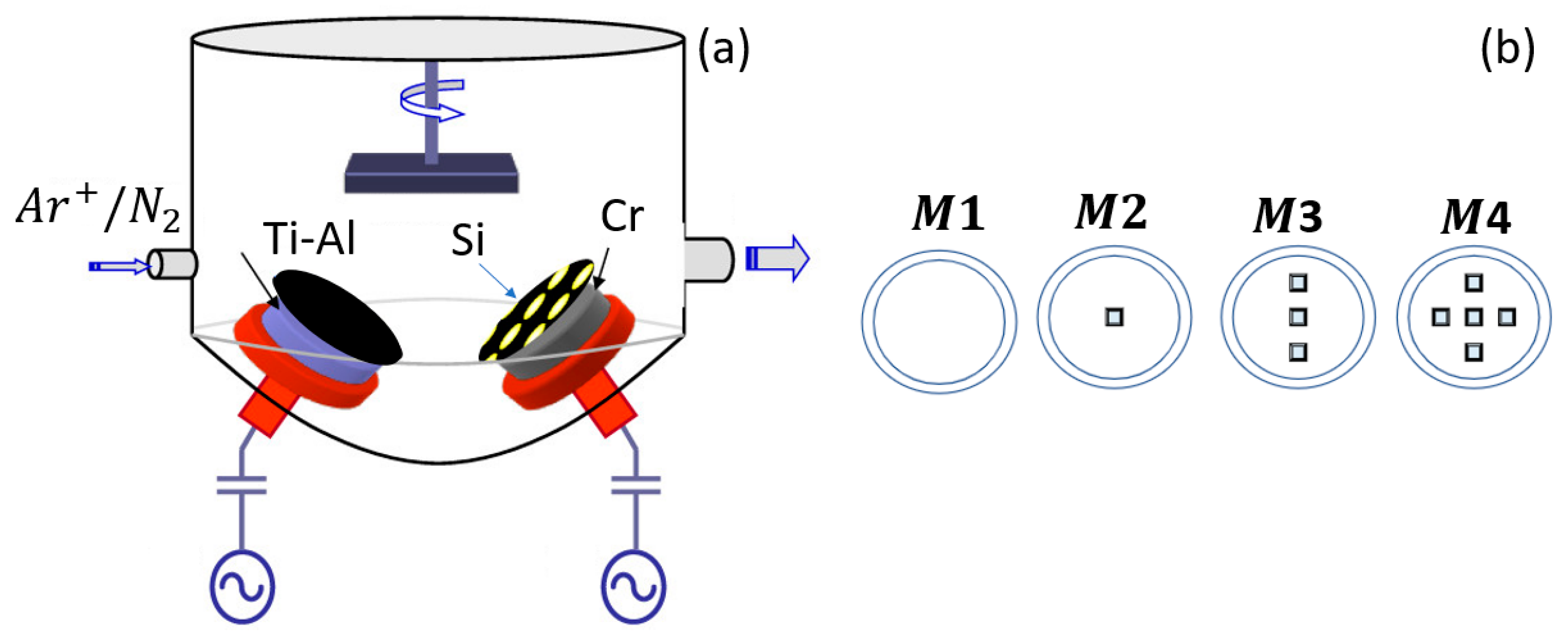
2.1. Coating Deposition

CrAlTiN coatings with different silicon contents were deposited using HIPIMS, equipped with one TiAl target (99.9%, TiAl = 50:50 wt.% with a diameter of 10.2 cm) and a Cr target (99.9% with a diameter of 10.2 cm). Figure 1 provides a schematic diagram of the deposition system employed in this study. Before deposition, the deposition chamber was evacuated to a pressure of 5 × 10⁻⁴ Pa. The substrates were heated and kept at a temperature of 200 °C, with the holder substrate rotating at 5.0 rpm. During the deposition process, the working pressure was maintained at a constant value of 0.5 Pa. The nitrogen flow ratio (N2) was controlled at 2 sccm using a mass-flow controller, while the flow of Ar gas was set to 14 sccm. The substrate-to-target separation was fixed at 10 cm, with a confocal angle of 60°. The substrate holder was electrically grounded and rotated at a speed of 13 rpm. A summary of the deposition conditions is presented in Table 1.
The deposition parameters used were constant for all the CrAlTiN samples obtained. The silicon content was adjusted by placing pieces distributed along the racetrack on the Cr target surface, which were 5 cubes of 4 mm × 4 mm × 4 mm. Three TiAlCrSiN coatings with Si contents of 0.0, 1.0, and 1.9 at.% were deposited. The number of deposition coatings was four, and they were named according to the number of Si pieces used: M1 (0.0 pieces), M2 (1.0 pieces), M3 (3.0 pieces), and M4 (5.0 pieces). The coatings’ thicknesses were measured at at least four points with a Bruker Contour GT optical profilometer (Bruker, Billerica, MA, USA) to obtain an average coating thickness. The deposition time was 40 min to achieve an approximate thickness of 1 micron. Finally, the CrAlTiN-Si coatings exhibited a single-layer structure.

2.2. Coating Characterization

The surface chemical composition was studied using XPS/UPS-ACenteno. The platform was equipped with a PHOIBOS 150 2D-DLD energy analyzer (SPECS group, Berlin, Germany), and for the measurements, a monochromatized Al Kα X-ray source (FOCUS 500, SPECS group, Berlin, Germany) operating at 100 W was utilized. The energy step of the hemispherical analyzer was adjusted to 100 eV for the general spectra and 20 eV for the high-resolution spectra. The carbon peak at 285 eV was used as a reference to correct any charge effects. Then, the samples were analyzed after Ar ion bombardment for 300 s. The ion beam current density was set at 1.66 μA/cm2. The deconvolution of the spectra was carried out using CasaXPS software (version 2.3.24, Casa Software Limited, Devon, UK), employing Gaussian–Lorentzian peak shapes and performing a Shirley-type background subtraction.
The microstructure was examined using a Bruker D8 advance diffractometer (Bruker, Billerica, MA, USA) with Cu-Kα radiation, a voltage of 40 mV, and a wavelength of 0.154 nm. The diffractograms were acquired using Bragg–Bretano geometry from 25° to 100°, and the crystalline sizes of the coatings were determined using the Debye–Scherrer equation [17]. The morphology of the coatings was investigated using a scanning electron microscope (SEM, Oxford X-act, Oxford Instruments, Abingdon, UK) with a secondary electron, and the chemical composition was determined with an energy-dispersive X-ray (EDX) spectroscopy probe using a Gifted Phenom microscope with EDX. The topography was determined using an atomic force microscope (AFM) in tapping mode (1 µ m × 1 µ m ) with a Nanowizard III for all coatings. Finally, the thicknesses of the coatings were measured by the means of a focused ion beam (FIB).
The nano-hardness (H) and elastic modulus (E) were evaluated with a Hysitron TriboIndenter nanoindenter (TI 750, Bruker, Billerica, MA, USA) equipped with a Berkovich-type diamond tip. An indentation force of 2.0 μ N was applied, and the indentation depth was limited to approximately 10% of the coatings’ thickness in order to avoid an influence of the substrate on the measurements. The H and E were determined by averaging the results of 20 indents on each coating and the ratios of H/E and H3/E2.

3. Results

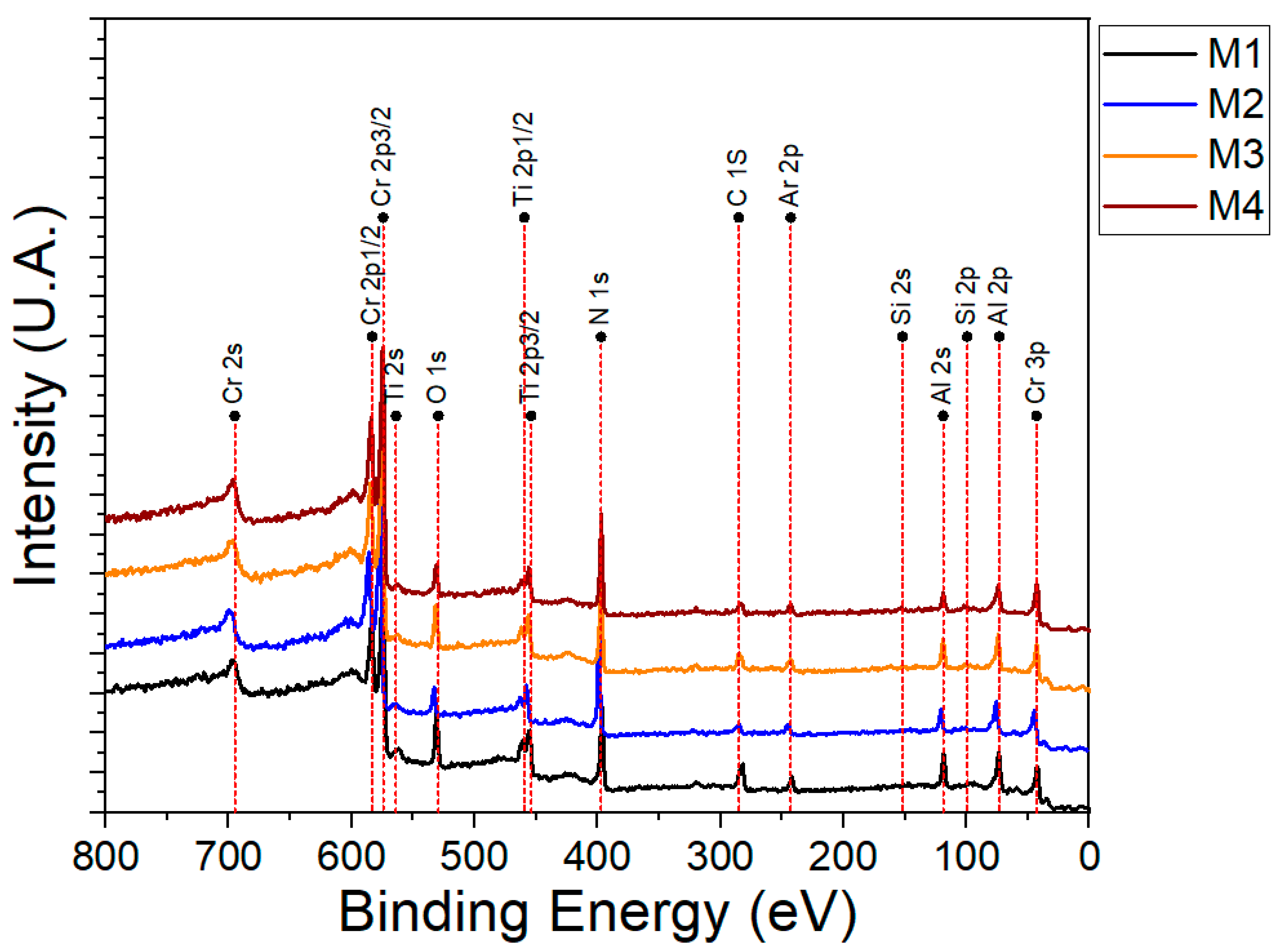
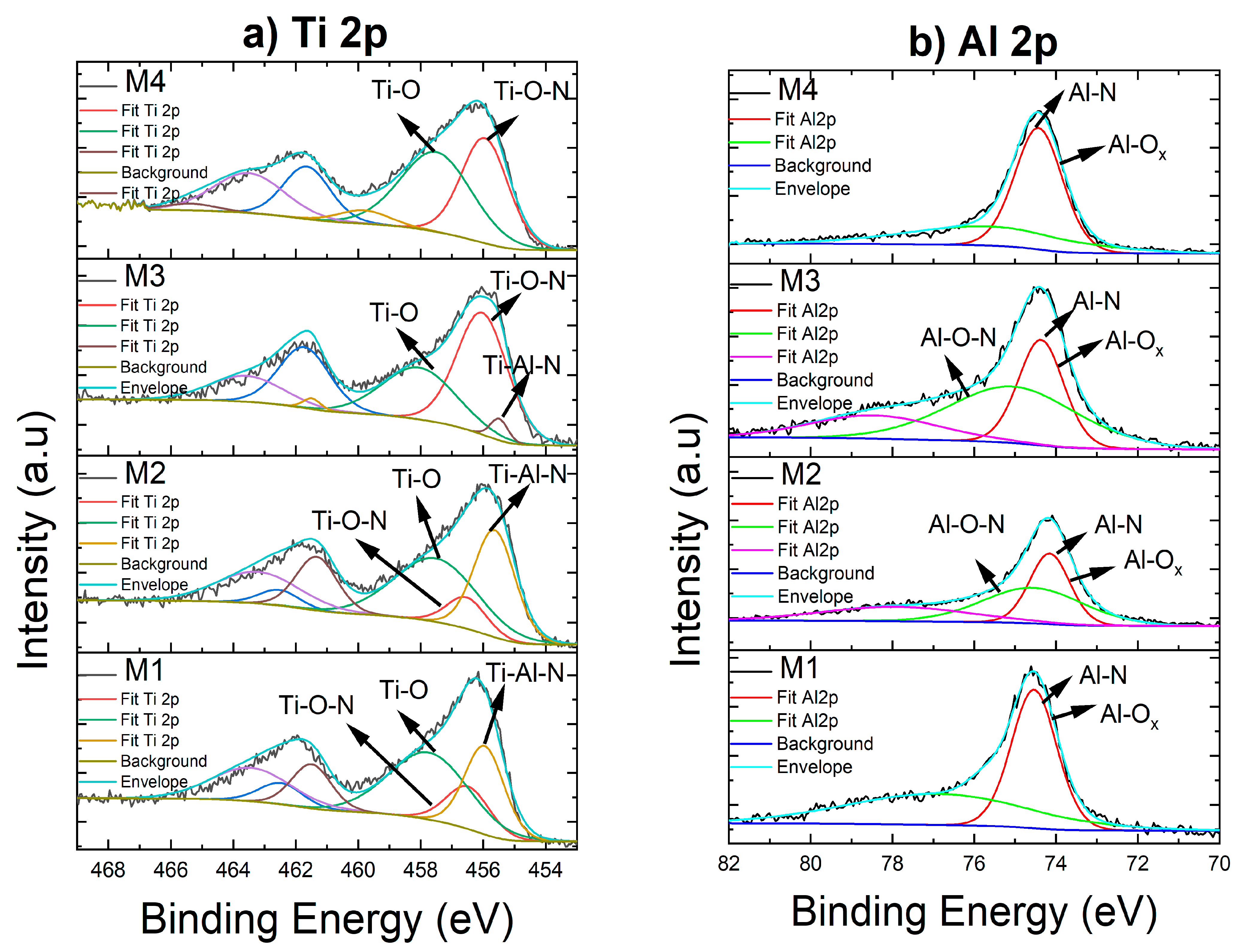
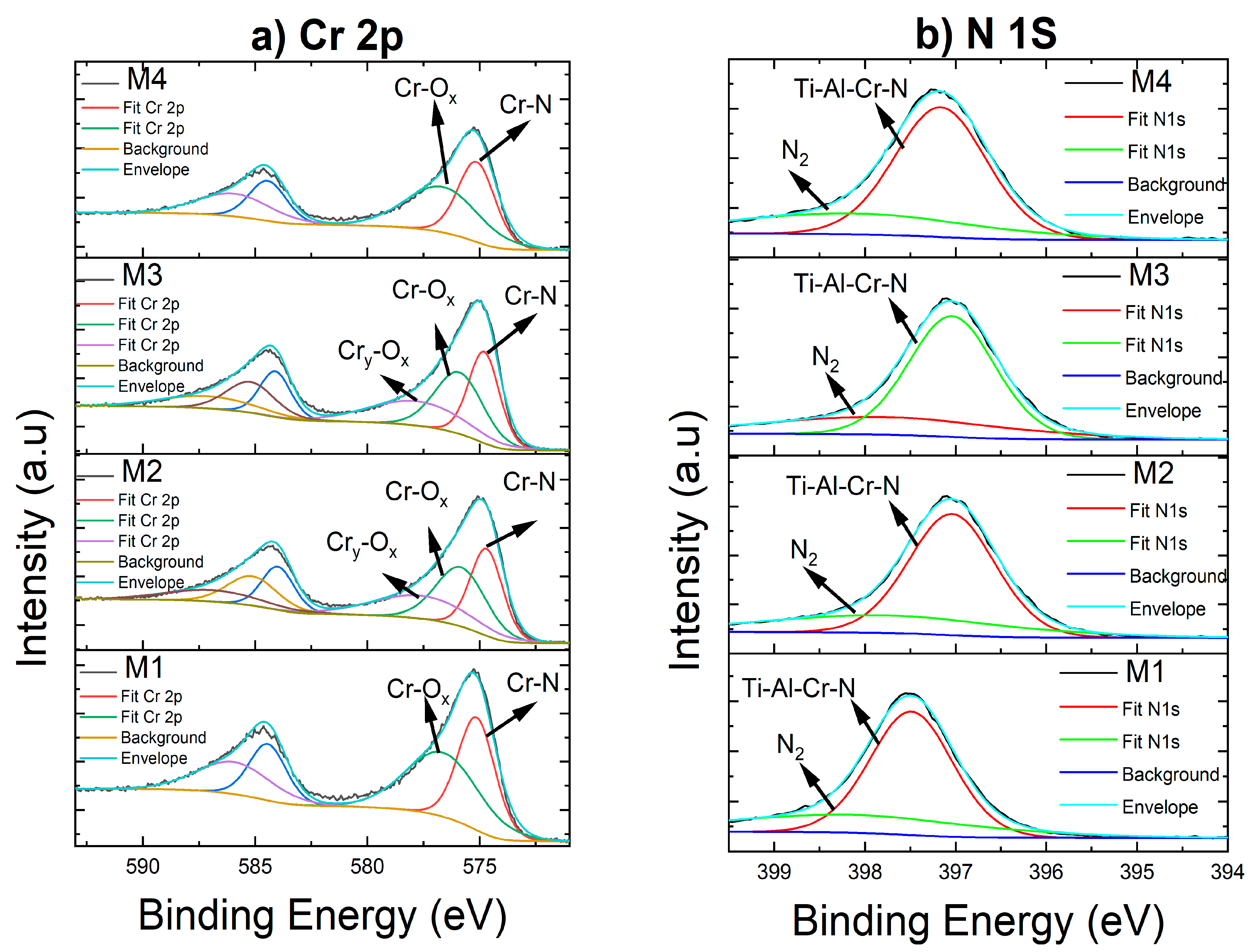
3.1. Chemical Composition

Table 2 shows the results of the characterization of the semiquantitative elemental chemical compositions of the deposited coatings, determined via EDS. The composition is presented with respect to the number of silicon pieces on the surface of the Cr target. As shown in Table 2, the elements titanium (Ti), aluminum (Al), chromium (Cr), silicon (Si), and nitrogen (N) could be distinguished in the coatings. The results revealed that the Si content in the coatings with 0.0, 1.0, 3.0, and 5.0 silicon pellets increased from 0.0 to 1.9 at.%. Additionally, the coatings demonstrated that the Ti and N contents remained constant with the Si incorporation, while the Al content increased from 15.7 to 17.2 at.%, accompanied by a reduction in the Cr content from 34.2 to 30.1 at.%. The absolute values of the N contents may not be accurate due to the limitation of EDS in measuring light elements.
The high amounts of Cr are associated with the use of a high-purity Cr target; however, the chromium concentration decreased as the Si pieces were placed on the target. This was due to the reduction in the area of greatest sputtering on the Cr target because of the location of the dopant material cubes in this area. A higher content of Al than that of Ti could also be seen in the coatings.
Sample M1 exhibited a high concentration of Cr due to the deposition parameters used, which involved high power being applied to the Cr target during the process and the higher sputtering yield of Cr compared to Ti and Al [25]. However, as the number of silicon pellets on the surface of the Cr target increased, the sputtering area decreased. Consequently, fewer Cr atoms were sputtered, increasing the Al content in the coatings. This resulted from the decrease in the sputtering area caused by the presence of the silicon pellets [26]. In addition, the difference in the composition of each element was seen as being due to the sputtering process, since it was strongly related to the sputtering yield (Cr > Al > Ti~Si) [27]. Finally, it is widely acknowledged that Si more readily reacted with nitrogen compared to Ti, Al, and Cr, because of its higher enthalpy formation values (−745.1 kJ/mol [28]) in contrast to TiN (−336.6 kJ/mol [28]), AlN (−318.6 kJ/mol), and CrN (−123.1 kJ/mol [28]). However, the literature on CrAlTiN-Si coatings [17,21] has shown that these elements form a face-centered cubic (fcc) substitutional solid solution structure of CrAlTiN embedded in an amorphous SiNx matrix.
The EDS technique has limitations in accurately detecting light elements such as carbon and oxygen. To address this, an X-ray photoelectron spectroscopy (XPS) analysis was conducted in order to investigate the surface chemical compositions of the CrAlTiN-Si coatings. The XPS survey spectrum of the coatings is presented in Figure 2. The results reveal the presence of Ti, Al, Cr, Ni, oxygen (O), and carbon (C) in the samples. Only the M4 coatings showed the presence of Si on their surfaces. It should be noted that the presence of O and C on the coatings’ surfaces was due to contamination from exposure to air.
The presence of oxygen can potentially lead to the formation of oxides, given the high tendency of Ti, Al, and Cr for oxide formation, as per their respective enthalpies of formation. After identifying the characteristic peaks in the spectra obtained from the survey, a quantitative analysis was performed, based on the relative peak intensity expressed by the peak areas. The results of this analysis are shown in Table 3. The compositional analysis, conducted through EDS and XPS, confirmed the presence of nitrogen in the coatings.
Hence, an analysis of the high-resolution XPS spectra was performed in order to verify the presence of these oxides on the surface. Figure 3, Figure 4 and Figure 5 show the high-resolution XPS core-level spectra of the Ti2p, Al2p, Cr2p, N1s, Si2p, and O1s of the CrAlTiN and CrAlTiN-Si coatings deposited. As shown in Figure 3a, all the Ti2p spectra can be fit to three spin-orbital doublet peaks ( T i 2 p 3 / 2 and T i 2 p 1 / 2 ) separated by 6.0 eV. The T i 2 p 3 / 2 peaks, located at about 456.2 ± 0.2 eV, 457.7 ± 0.2 eV, and 455.7 ± 0.2 eV, correspond to Ti-O-N bonds [13,29,30], Ti-O (TiO2) bonds [13,31], and Ti-Al-Cr-N (CrAlTiN solution solid) bonds [6,30], respectively. The presence of oxides and oxynitrides in the coatings can be attributed to the vacuum chamber and exposure to air [32], as titanium has a higher affinity for O atoms. Figure 3b displays the Al2p spectra of all the coatings deposited, which can be fit with three components at binding energies of 74.5 ± 0.1 eV, 75.5 ± 0.4 eV, and 77.7 ± 0.6 eV. The peak at 74.5 ± 0.1 eV can be attributed to Al-N bonds (AlN), but could also be associated with Ti-Al-Cr-N bonds, as suggested by the Ti2p spectra [30]. The peak at 75.5 ± 0.4 eV corresponds to Al-N bonds (AlN), except for the M2 samples, which exhibit a peak at 74.1 eV, associated with the formation of non-stoichiometric AlNx compounds. The highest binding energy value was contributed by Al-O bonds [13,30].
The Cr2p spectra in Figure 4a show C r 2 p 3 / 2 and C r 2 p 1 / 2 peaks separated by 9.3 eV. The C r 2 p 3 / 2 peak located at 574.9 ± 0.2 eV can be related to Cr-N (CrN) bonds [31,33], while the peaks located at 576.1 ± 0.3 eV and 577.8 ± 0.3 eV are characteristic of Cr-O bonds [33]. Additionally, the N1s spectra, Figure 4b, of all the coatings reveal the presence of two peaks. All the samples exhibit a peak centered at 397.3 ± 0.2 eV, which can be attributed to nitrides such as TiN, AlN, or CrN, or a solid solution of CrAlTiN, due to the similarity in the binding energy values of these nitrides [18,32,34]. However, for the M1 sample, a second peak is located at 398.1 eV, which is associated with N2 surface absorbates [30], while for the M2, M3, and M4 samples, the second peak is located at 398.0 ± 0.2 eV, corresponding to Si-N bonds (Si3N4) [18].
For the Si2p spectra, Figure 5a, a single peak at a binding energy of 102.0 ± 0.1 eV was detected in the coatings with silicon (samples M3 and M4), which was assigned to Si3N4 [18,31,33]. In addition, the O1s peaks, Figure 5b, located at 531.7 ± 0.2 eV and 532.9 ± 0.2 eV, indicate the presence of oxides [13,35] and absorbed oxygen or water molecules on the surfaces, respectively [13]. The absence of metallic peaks suggests that the atoms’ surfaces reacted with nitrogen atoms during deposition. Finally, the XPS results show that, regardless of the silicon content of the coatings, the XPS spectra exhibit no shifts in the binding energy. The results agree with studies conducted by W. Tillmann et al. for Si-doped CrAlN coatings deposited using magnetron sputtering [30].

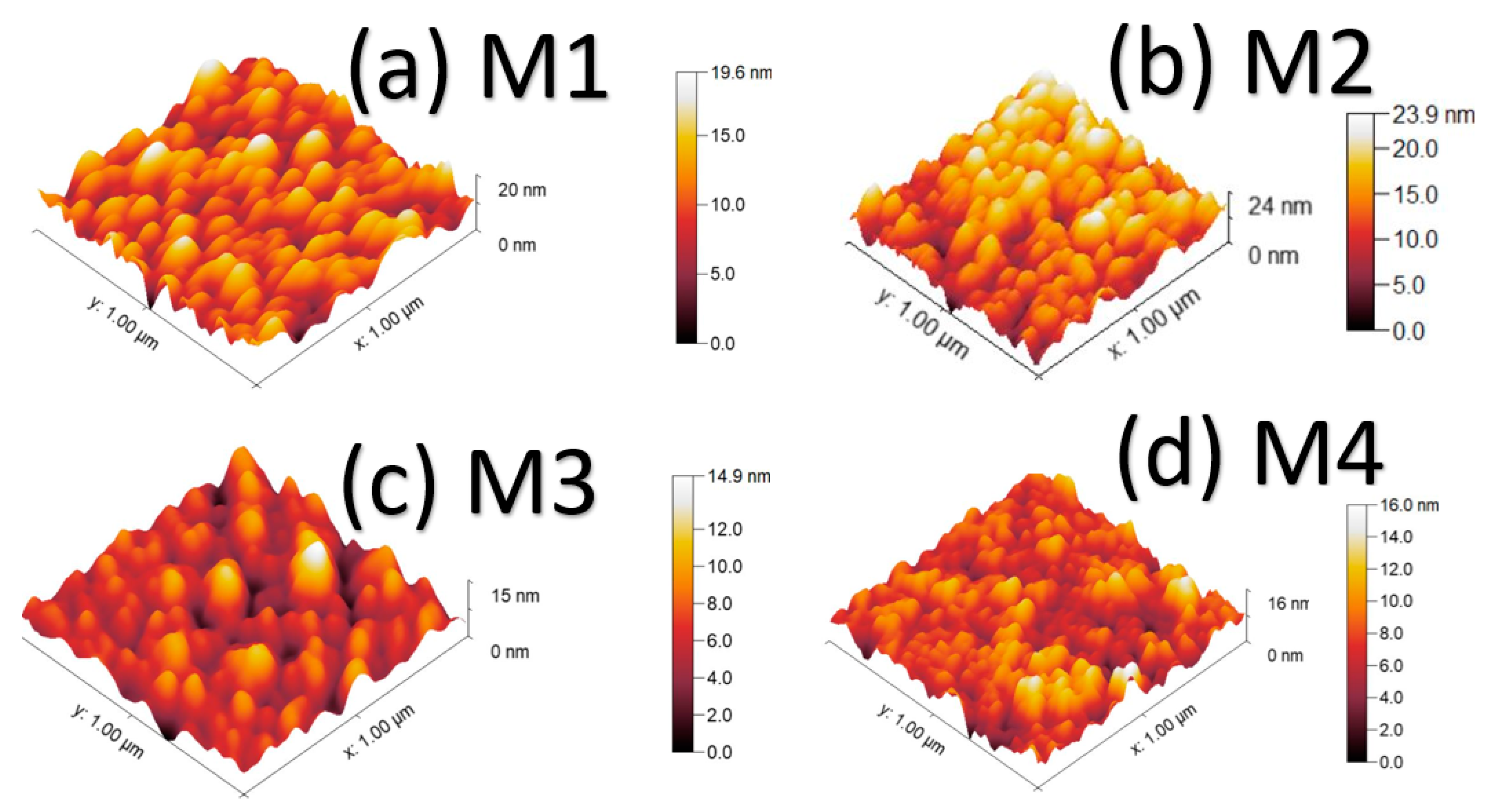
3.2. Morphological Characterization

In order to investigate the morphology of the deposited coatings, the SEM surface images of CrAlTiN with different Si contents are shown in Figure 6. All the deposited coatings showed very dense and smooth surfaces. In addition, it is possible to observe cauliflower-type morphology in all the coatings. These results are similar to those reported by other authors, where cauliflower-type morphology occurs when small grains combine to form a large column-size structure [24,36]. Furthermore, it has been reported that the HiPIMs technique generates a high degree of ionization flux, which improves the roughness and density of coatings [24]. Finally, no significant changes in the surface morphologies of the coatings were observed with the incorporation of silicon.
AFM images of the surfaces of the deposited coatings were taken in order to determine the surface roughness of the coatings, as shown in Figure 7. A granular morphology was evident across all the coatings [27]. The average surface roughness (Ra) values are presented in Table 4.
Overall, an observable reduction in roughness could be noted with an increasing Si content. This decrease in surface roughness is attributable to the refinement of the grain size, as will be demonstrated in the following XRD results [37].

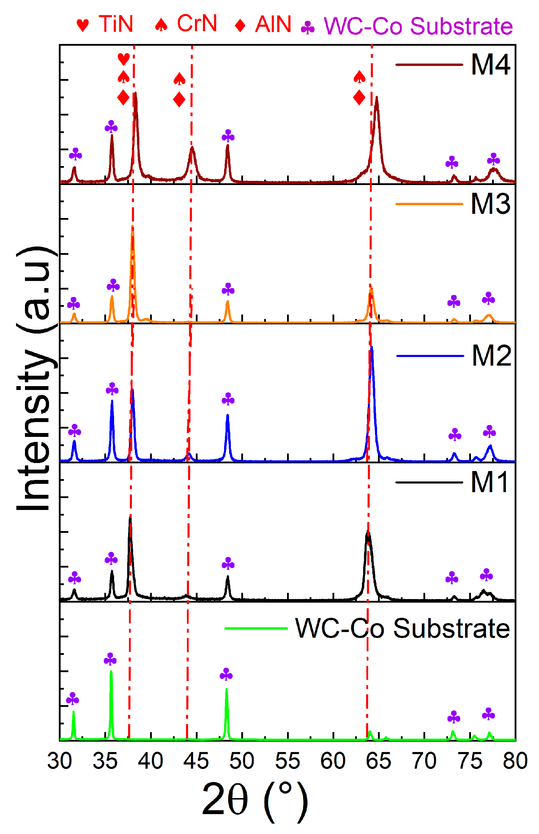
3.3. Structural Characterization

To analyze the microstructures, XRD patterns of the CrAlTiN-Si coatings deposited on WC-Co substrates are presented in Figure 8. For the M1 sample, excluding the substrate contribution, the XRD results showed that the coating exhibits two diffraction peaks, centered around 37.6° (with the highest intensity) and 43.9° (with lower intensity), which correspond to the positions between the angles for face-centered cubic TiN (JCPDS 00-38-1420), AlN (JCPDS 00-025-1495), and CrN (JCPDS 03-065-2899). These observations suggest the formation of an fcc solid solution [10,11,19,21]. The peak at 2 θ = 37.6° corresponds to the 111 plane, while the peak at 43.9° corresponds to the 200 plane of the fcc-NaCl-type structure. However, upon Si incorporation, a slight shift towards higher angles was observed in the diffraction peaks. The lattice parameters and crystallite sizes of the CrAlTiN coatings with varying silicon contents were determined from the XRD results and are presented in Table 5.
The lattice parameter of the M1 sample was determined to be 0.412 nm, which is lower than the lattice parameter of CrN (0.414 nm). The lattice parameter decreased to a minimum value of 0.409 nm for the M3 sample with the incorporation of Si. Moreover, when the Si content exceeded 1.0 at.%, the lattice parameter increased to 0.413 nm.
The coatings can be categorized into two groups according to the silicon content and lattice parameter. In the first group, the lattice parameter decreased from 0.412 nm to 0.409 nm as the Si content increased from 0.0 to 1.0 at.%. This change in the lattice parameter implied the incorporation of silicon atoms into the interstitial sites of the crystalline structure of CrAlTiN-Si. The variation in the lattice parameter can be attributed to the smaller atomic radius of Si (0.118 nm) compared to those of Ti (0.145 nm), Cr (0.125 nm), and Al (0.143 nm). Therefore, the substitution of Si atoms for Ti, Cr, and Al atoms led to a compression effect on the lattice of the CrAlTiN coatings. Furthermore, it may be attributed to the formation of a nanocomposite phase, where Si exists either within the CrAlTiN lattice or in the amorphous SiNx phase.
In the second group, as the silicon content increased from 1.0 at.% to 1.9 at.%, the lattice parameter of the CrAlTiN-Si coatings increased from 0.409 nm to 0.413 nm. The expansion of the lattice in these CrAlTiN-Si coatings can be attributed to the substitution of Cr atoms with more Al atoms [21].
Similar results were reported by Chang et al. [34], who deposited CrSiN coatings with different Si contents through reactive direct current magnetron co-sputtering. They found that the lattice parameters of the CrSiN coatings changed as the Si content increased from 0 to 12 at.%, indicating the substitution of Cr with Si in the CrN lattice. However, at 14 at.%, a nanocomposite phase formed and increased the lattice parameter. Additionally, the effect of the residual stress should also be considered. Y-C. Kuo et al. [21] researched CrTiAlN and CrTiAlSiN coatings with different silicon contents prepared using magnetron co-sputtering. They found that all the coatings exhibited a NaCl B1 crystal structure. Moreover, the authors reported that an increase in Si content resulted in an observed increase in the lattice parameter from 0.4193 nm to 0.4227 nm, accompanied by a reduction in the grain size from 12.4 nm to 5.8 nm.
Previous studies [10,24] with other coatings have shown that the introduction of doping elements can influence the intrinsic stress of compound coatings, resulting in a slight shift of = X-ray diffraction peaks towards higher angles as the dopant content increases. For example, Gui et al. [24] deposited TiAlCrN ceramic coatings with different Ti contents using a hybrid deposition technique involving HiPIMS and DC magnetron sputtering. They observed similar behavior upon the Ti incorporation into the AlCrN matrix. As the Ti content increased, the matrix underwent distortion, leading to a shift in the diffraction peaks towards higher angles, and, consequently, a higher intrinsic stress.
The M1 sample exhibited a crystallite size of 20.0 nm, as indicated in Table 5. With the incorporation of Si, the crystallite sizes increased, reaching 23.5 nm at a Si content of 1.0 at.%. However, as the Si content increased to 1.9 at.%, the crystallite size decreased to 17.2 nm. This reduction in crystallite size can be attributed to the distinctive microstructure present in the coating. Previous studies [18,21,38,39,40] have indicated that incorporating Si results in the formation of a nanocomposite coating, characterized by the presence of nanocrystallites of CrAlTiSiN embedded within an amorphous SiNx matrix. Moreover, it has been reported that, with an increase in Si content, the amorphous SiNx phase also increases, resulting in a decrease in the crystallite size of coatings.
Finally, no diffraction peaks from hcp-AlN, S i 3 N 4 , or hcp- C r 2 N were observed. However, the XPS results showed the presence of Si-N bonds, indicating that the SiNx phase was either amorphous in the coatings or the low silicon concentration could not be detected using the XRD technique, as reported by A. Miletic et al. [31].

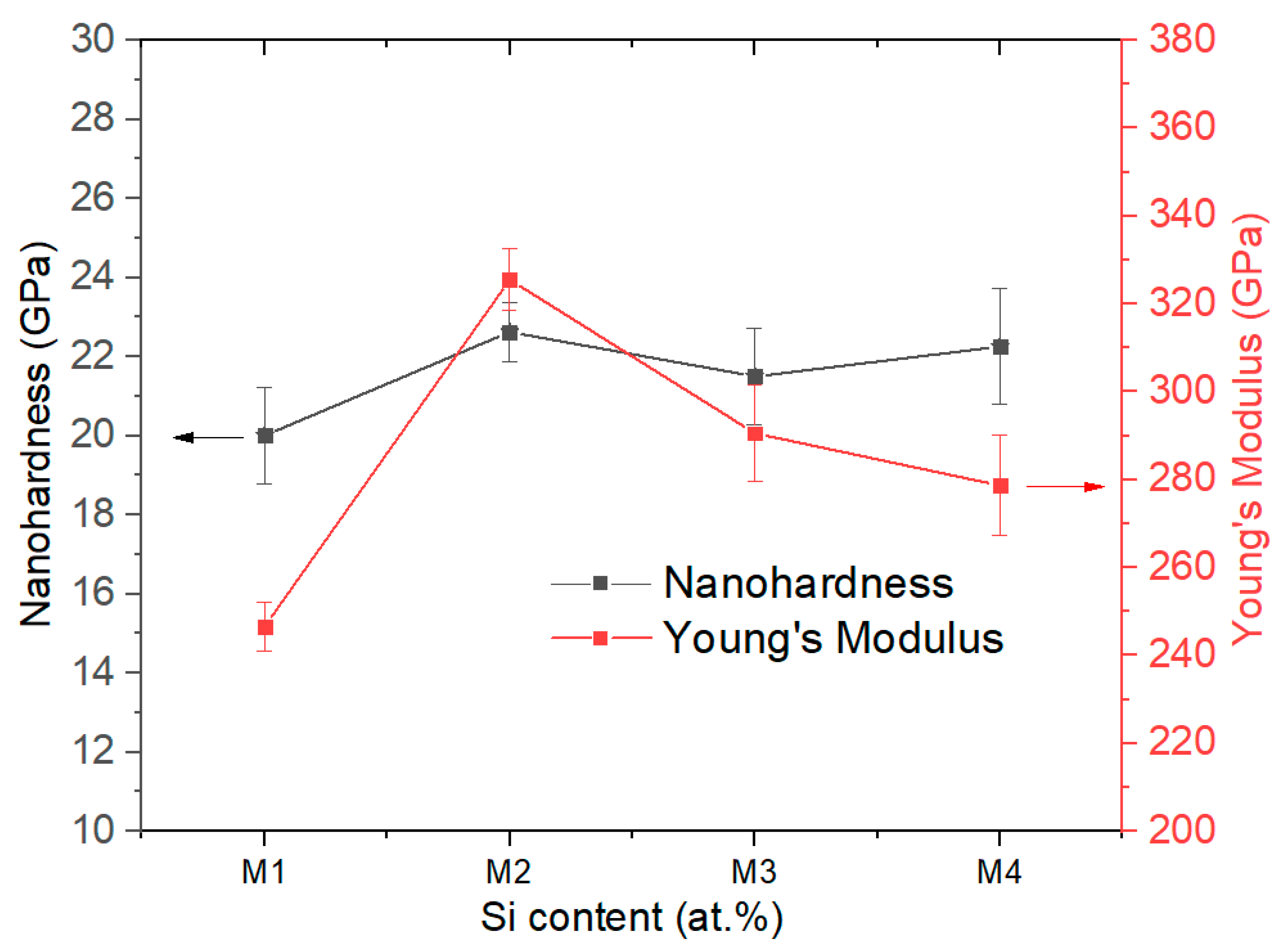
3.4. Mechanical Properties

The mechanical properties obtained from the nanoindentation tests are shown in Figure 9 and Table 6. The results demonstrate that incorporating silicon (Si) enhanced the nano-hardness (H) of the coatings. However, the H values of the three coatings containing silicon (samples M2, M3, and M4) exhibited a similar range, approximately 21.5–22.6 GPa. These higher nano-hardness values can be explained by the solid solution’s hardening effect, as suggested by the XRD diffraction result. This behavior can be attributed to the formation of a nanocomposite phase, where Si existed either within the CrAlTiN lattice or in the amorphous SiNx phase.
Introducing Si elements into the CrAlTiN matrix resulted in significant differences in atomic size, leading to lattice distortion and solid solution strengthening. This phenomenon is consistent with findings reported by B. Gui et al. [24], where Ti elements were doped into AlCrN crystal lattices. Moreover, Si incorporation also promoted the formation of an amorphous SINx phase, which, in turn, refined the grain structure and impacted the coatings’ density, ultimately contributing to enhancing their hardness. Another important effect observed in Figure 9 and Table 5 is the decrease in the Young’s modulus with an increasing silicon content. This phenomenon indicates that the presence of silicon led to a reduction in the coatings’ rigidity.
The elastic limit of strain (H/E) and the resistance to plastic deformation (H3/E2) were calculated based on the nano-hardness and Young’s modulus values, as presented in Table 5. The results indicated a decrease in the plastic deformation with the Si incorporation, specifically from 0.0 to 0.1 at.% of Si. However, as the Si content increased from 0.1 to 1.9 at.%, both the H / E and H 3 / E 2 ratios exhibited an increase. According to H.A. Macías et al. [41], higher H / E and H 3 / E 2 values indicate a better wear resistance. This observation suggests that the presence of Si effectively impeded crack propagation, consequently enhancing the toughness and fracture resistance of the coatings as the Si content increased.

4. Conclusions

We successfully deposited CrAlTiN-Si coatings with different silicon contents on commercial K20 steel substrates using the high-power impulse magnetron sputtering (HiPIMS) technique. By incorporating Si pellets onto the Cr target’s surface, coatings with silicon contents of 0 at.%, 0.1 at.%, 1.0 at.%, and 1.9 at.% were obtained. Analyses using EDS and XPS confirmed the presence of nitrogen within the coatings and nitrogen, oxygen, and carbon on the surfaces of the coatings. Additionally, an XPS analysis verified the formation of silicon nitride in the coatings when the silicon content was 1.9 at.%.
All the coatings exhibited a dense, smooth surface with the typical cauliflower-type morphology commonly observed in coatings deposited using HiPIMs. Furthermore, the roughness of the coatings decreased with an increasing Si content. The XRD analysis revealed that silicon contents ranging from 0 to 1.0 at.% resulted in the formation of a face-centered cubic (fcc) solid solution within the coatings. However, at a silicon content of 1.9 at.%, a nanocomposite phase consisting of an fcc solid solution of CrAlTiSiN and an amorphous phase of SiNx was observed. The nanoindentation test demonstrated that the incorporation of silicon improved the nano-hardness of the coatings, with values ranging from approximately 21.5 to 22.6 GPa, compared to the coatings without silicon, which exhibited a nano-hardness of 20.0 GPa. Additionally, as the Si content increased from 0.1 to 1.9 at.%, both the H / E and H 3 / E 2 ratios exhibited increases.

Author Contributions

Conceptualization, A.F.O.J., H.S.V., C.M.M., J.J.O. and Y.P.; methodology, A.F.O.J. and J.J.O.; investigation, A.F.O.J., C.M.M. and J.J.O.; resources, A.F.O.J., H.S.V., J.J.O. and Y.P.; writing—review and editing, A.F.O.J., H.S.V., C.M.M., J.J.O. and Y.P. All authors have read and agreed to the published version of the manuscript.

Funding

This investigation was carried out with financial support from MINCIENCIAS through the project with contract 808-2018.

Data Availability Statement

Not applicable.

Acknowledgments

The authors would like to thank CEIT-San Sebastian (Spain) for their continuing support for experimental activities and their instrumental assistance.

Conflicts of Interest

The authors declare no conflict of interest.

References

  1. Von Fieandt, L.; Larsson, T.; Lindahl, E.; Bäcke, O.; Boman, M. Chemical Vapor Deposition of TiN on Transition Metal Substrates. Surf. Coat. Technol. 2018, 334, 373–383. [Google Scholar] [CrossRef]
  2. Das, K.; Sen, S.; Joseph, A.; Ghosh, A.; Rane, R.; Biswas, K.; Mukherjee, S.; Ghosh, M. Investigation on the Effects of Pretreatment on the Surface Characteristics of Duplex Plasma-Treated AISI P20 Tool Steel. Materialia 2023, 27, 101679. [Google Scholar] [CrossRef]
  3. Beake, B.D.; Bird, A.; Isern, L.; Endrino, J.L.; Jiang, F. Elevated Temperature Micro-Impact Testing of TiAlSiN Coatings Produced by Physical Vapour Deposition. Thin Solid Film. 2019, 688, 137358. [Google Scholar] [CrossRef]
  4. Alhafian, M.R.; Chemin, J.B.; Valle, N.; El Adib, B.; Penoy, M.; Bourgeois, L.; Ghanbaja, J.; Barrirero, J.; Soldera, F.; Mücklich, F.; et al. Study of the Oxidation Mechanism at High Temperature of Nanofiber Textured AlTiCrN Coatings Produced by Physical Vapor Deposition Using High-Resolution Characterization Techniques. Corros. Sci. 2022, 201, 110226. [Google Scholar] [CrossRef]
  5. Beake, B.D.; Isern, L.; Endrino, J.L.; Fox-Rabinovich, G.S. Micro-Impact Testing of AlTiN and TiAlCrN Coatings. Wear 2019, 418–419, 102–110. [Google Scholar] [CrossRef]
  6. Fox-Rabinovich, G.S.; Kovalev, A.I.; Aguirre, M.H.; Beake, B.D.; Yamamoto, K.; Veldhuis, S.C.; Endrino, J.L.; Wainstein, D.L.; Rashkovskiy, A.Y. Design and Performance of AlTiN and TiAlCrN PVD Coatings for Machining of Hard to Cut Materials. Surf. Coat. Technol. 2009, 204, 489–496. [Google Scholar] [CrossRef]
  7. Guo, D.; Yu, D.; Zhang, P.; Song, W.; Zhang, B.; Peng, K. Laminar Plasma Jet Surface Hardening of P20 Mold Steel: Analysis on the Wear and Corrosion Behaviors. Surf. Coat. Technol. 2021, 415, 127129. [Google Scholar] [CrossRef]
  8. Yan, G.; Lu, S.; Zhang, M.; Wang, J.; Yang, X.; Zhang, Z.; Gu, J.; Li, C. Wear and Corrosion Behavior of P20 Steel Surface Modified by Gas Nitriding with Laser Surface Engineering. Appl. Surf. Sci. 2020, 530, 147306. [Google Scholar] [CrossRef]
  9. Shakerin, S.; Sanjari, M.; Pirgazi, H.; Amirkhiz, B.S.; Mohammadi, M. On the Bending of MS1-P20 Hybrid Steels Additively Manufactured Using Laser Powder Bed Fusion. Materialia 2022, 24, 101501. [Google Scholar] [CrossRef]
  10. Danek, M.; Fernandes, F.; Cavaleiro, A.; Polcar, T. Influence of Cr Additions on the Structure and Oxidation Resistance of Multilayered TiAlCrN Films. Surf. Coat. Technol. 2017, 313, 158–167. [Google Scholar] [CrossRef]
  11. Fernandes, F.; Danek, M.; Polcar, T.; Cavaleiro, A. Tribological and Cutting Performance of TiAlCrN Films with Different Cr Contents Deposited with Multilayered Structure. Tribol. Int. 2018, 119, 345–353. [Google Scholar] [CrossRef]
  12. Kovalev, A.I.; Wainstein, D.L.; Rashkovskiy, A.Y.; Fox-Rabinovich, G.S.; Yamamoto, K.; Veldhuis, S.; Aguirre, M.; Beake, B.D. Impact of Al and Cr Alloying in TiN-Based PVD Coatings on Cutting Performance during Machining of Hard to Cut Materials. Vacuum 2009, 84, 184–187. [Google Scholar] [CrossRef]
  13. Chen, J.T.; Wang, J.; Zhang, F.; Zhang, G.A.; Fan, X.Y.; Wu, Z.G.; Yan, P.X. Characterization and Temperature Controlling Property of TiAlN Coatings Deposited by Reactive Magnetron Co-Sputtering. J. Alloys Compd. 2009, 472, 91–96. [Google Scholar] [CrossRef]
  14. Liew, W.Y.H.; Lim, H.P.; Melvin, G.J.H.; Dayou, J.; Jiang, Z.T. Thermal Stability, Mechanical Properties, and Tribological Performance of TiAlXN Coatings: Understanding the Effects of Alloying Additions. J. Mater. Res. Technol. 2022, 17, 961–1012. [Google Scholar] [CrossRef]
  15. Lim, H.P.; Jiang, Z.T.; Melvin, G.J.H.; Nayan, N.; Chee, F.P.; Soon, C.F.; Hassan, N.; Liew, W.Y.H. A Systematic Investigation of the Tribological Behaviour of Oxides Formed on AlSiTiN, CrAlTiN, and CrAlSiTiN Coatings. Wear 2023, 512–513, 204552. [Google Scholar] [CrossRef]
  16. Huang, B.; Liu, L.T.; Du, H.M.; Chen, Q.; Liang, D.D.; Zhang, E.G.; Zhou, Q. Effect of Nitrogen Flow Rate on the Microstructure, Mechanical and Tribological Properties of CrAlTiN Coatings Prepared by Arc Ion Plating. Vacuum 2022, 204, 111336. [Google Scholar] [CrossRef]
  17. Bobzin, K.; Brögelmann, T.; Kruppe, N.C.; Carlet, M. HPPMS TiAlCrSiN—Influence of Substrate Bias and Pulse Frequency on Cutting Performance. Surf. Coat. Technol. 2020, 397, 126056. [Google Scholar] [CrossRef]
  18. Chen, H.; Zheng, B.C.; Li, Y.G.; Wu, Z.L.; Lei, M.K. Flexible Hard TiAlSiN Nanocomposite Coatings Deposited by Modulated Pulsed Power Magnetron Sputtering with Controllable Peak Power. Thin Solid Film. 2019, 669, 377–386. [Google Scholar] [CrossRef]
  19. Chen, W.; Wu, W.; Huang, Y.; Wu, D.; Li, B.; Wang, C.; Wang, Y.; Li, S.Y. Influence of Annealing on Microstructures and Mechanical Properties of Arc-Deposited AlCrTiSiN Coating. Surf. Coat. Technol. 2021, 421, 127470. [Google Scholar] [CrossRef]
  20. Fuentes, G.G.; Almandoz, E.; Pierrugues, R.; Martínez, R.; Rodríguez, R.J.; Caro, J.; Vilaseca, M. High Temperature Tribological Characterisation of TiAlSiN Coatings Produced by Cathodic Arc Evaporation. Surf. Coat. Technol. 2010, 205, 1368–1373. [Google Scholar] [CrossRef]
  21. Kuo, Y.C.; Wang, C.J.; Lee, J.W. The Microstructure and Mechanical Properties Evaluation of CrTiAlSiN Coatings: Effects of Silicon Content. Thin Solid Film. 2017, 638, 220–229. [Google Scholar] [CrossRef]
  22. Cao, F.; Munroe, P.; Zhou, Z.; Xie, Z. Mechanically Robust TiAlSiN Coatings Prepared by Pulsed-DC Magnetron Sputtering System: Scratch Response and Tribological Performance. Thin Solid Film. 2018, 645, 222–230. [Google Scholar] [CrossRef]
  23. Zhang, D.; Zuo, X.; Wang, Z.; Li, H.; Chen, R.; Wang, A.; Ke, P. Comparative Study on Protective Properties of CrN Coatings on the ABS Substrate by DCMS and HiPIMS Techniques. Surf. Coat. Technol. 2020, 394, 125890. [Google Scholar] [CrossRef]
  24. Gui, B.; Zhou, H.; Zheng, J.; Liu, X.; Feng, X.; Zhang, Y.; Yang, L. Microstructure and Properties of TiAlCrN Ceramic Coatings Deposited by Hybrid HiPIMS/DC Magnetron Co-Sputtering. Ceram. Int. 2021, 47, 8175–8183. [Google Scholar] [CrossRef]
  25. Xu, Y.X.; Riedl, H.; Holec, D.; Chen, L.; Du, Y.; Mayrhofer, P.H. Thermal Stability and Oxidation Resistance of Sputtered Ti-Al-Cr-N Hard Coatings. Surf. Coat. Technol. 2017, 324, 48–56. [Google Scholar] [CrossRef]
  26. Vanegas, P.H.S.; Calderon, V.S.; Alfonso, O.J.E.; Olaya, F.J.J.; Ferreira, P.J.; Carvalho, S. Influence of Silicon on the Microstructure and the Chemical Properties of Nanostructured ZrN-Si Coatings Deposited by Means of Pulsed-DC Reactive Magnetron Sputtering. Appl. Surf. Sci. 2019, 481, 1249–1259. [Google Scholar] [CrossRef]
  27. Lin, C.H.; Duh, J.G.; Yeh, J.W. Multi-Component Nitride Coatings Derived from Ti–Al–Cr–Si–V Target in RF Magnetron Sputter. Surf. Coat. Technol. 2007, 201, 6304–6308. [Google Scholar] [CrossRef]
  28. Daniel, R.; Musil, J. Novel Nanocomposite Coatings: Advances and Industrial Applications, 1st ed.; CRC Press: Boca Raton, FL, USA, 2013; ISBN 9789814411189. [Google Scholar]
  29. Zhou, B.; Wang, Y.; Liu, Z.; Zhi, J.; Sun, H.; Wang, Y.; Wu, Y.; Hei, H.; Yu, S. Effect of Modulation Ratio on Microstructure and Tribological Properties of TiAlN/TiAlCN Multilayer Coatings Prepared by Multi-Excitation Source Plasma. Vacuum 2023, 211, 111917. [Google Scholar] [CrossRef]
  30. Cao, H.S.; Liu, F.J.; Hao, L.I.; Luo, W.Z.; Qi, F.G.; Lu, L.W.; Nie, Z.H.; Ouyang, X.P. Effect of Bias Voltage on Microstructure, Mechanical and Tribological Properties of TiAlN Coatings. Trans. Nonferrous Met. Soc. China 2022, 32, 3596–3609. [Google Scholar] [CrossRef]
  31. Miletić, A.; Panjan, P.; Čekada, M.; Kovačević, L.; Terek, P.; Kovač, J.; Dražič, G.; Škorić, B. Nanolayer CrAlN/TiSiN Coating Designed for Tribological Applications. Ceram. Int. 2021, 47, 2022–2033. [Google Scholar] [CrossRef]
  32. Zhang, L.; Shen, Y.Q.; Zhao, Y.M.; Chen, S.N.; Ouyang, X.; Zhang, X.; Liang, H.; Liao, B.; Chen, L. Structure Control of High-Quality TiAlN Monolithic and TiAlN/TiAl Multilayer Coatings Based on Filtered Cathodic Vacuum Arc Technique. Surf. Interfaces 2023, 38, 102836. [Google Scholar] [CrossRef]
  33. Polcar, T.; Cavaleiro, A. High Temperature Properties of CrAlN, CrAlSiN and AlCrSiN Coatings—Structure and Oxidation. Mater. Chem. Phys. 2011, 129, 195–201. [Google Scholar] [CrossRef]
  34. Chang, L.C.; Sung, M.C.; Chen, Y.I. Effects of Bias Voltage and Substrate Temperature on the Mechanical Properties and Oxidation Behavior of CrSiN Films. Vacuum 2021, 194, 110580. [Google Scholar] [CrossRef]
  35. Wu, J.; He, N.; Li, H.; Liu, X.; Ji, L.; Huang, X.; Chen, J. Deposition and Characterization of TiAlSiN Coatings Prepared by Hybrid PVD Coating System. Surf. Interface Anal. 2015, 47, 184–191. [Google Scholar] [CrossRef]
  36. Cavaleiro, D.; Carvalho, S.; Cavaleiro, A.; Fernandes, F. TiSiN(Ag) Films Deposited by HiPIMS Working in DOMS Mode: Effect of Ag Content on Structure, Mechanical Properties and Thermal Stability. Appl. Surf. Sci. 2019, 478, 426–434. [Google Scholar] [CrossRef]
  37. Chang, L.C.; Liu, Y.H.; Chen, Y.I. Mechanical Properties and Oxidation Behavior of Cr-Si-N Coatings. Coatings 2019, 9, 528. [Google Scholar] [CrossRef]
  38. Bobzin, K.; Brögelmann, T.; Kruppe, N.C.; Carlet, M. Nanocomposite (Ti,Al,Cr,Si)N HPPMS Coatings for High Performance Cutting Tools. Surf. Coat. Technol. 2019, 378, 124857. [Google Scholar] [CrossRef]
  39. Vanegas, H.S.; Alfonso, J.E.; Olaya, J.J. Effect of Si Content on Functional Behavior of Nanostructured Coatings of Zr-Si-N. Mater. Res. Express 2019, 6, 115076. [Google Scholar] [CrossRef]
  40. Bobzin, K.; Brögelmann, T.; Kruppe, N.C.; Carlet, M. Wear Behavior and Thermal Stability of HPPMS (Al,Ti,Cr,Si)ON, (Al,Ti,Cr,Si)N and (Ti,Al,Cr,Si)N Coatings for Cutting Tools. Surf. Coat. Technol. 2020, 385, 125370. [Google Scholar] [CrossRef]
  41. Macías, H.A.; Yate, L.; Coy, L.E.; Olaya, J.J.; Aperador, W. Effect of Nitrogen Flow Ratio on Microstructure, Mechanical and Tribological Properties of TiWSiN × Thin Film Deposited by Magnetron Co-Sputtering. Appl. Surf. Sci. 2018, 456, 445–456. [Google Scholar] [CrossRef]
Figure 1. (a) Schematic diagram of the deposition system and (b) the arrangement of silicon pieces positioned atop the surface of the Cr target.
Metals 13 01691 g001
Figure 2. XPS survey spectrum of CrAlTiN-Si coatings.
Metals 13 01691 g002
Figure 3. (a) Ti2p, (b) Al2p, XPS spectra of CrAlTiN coatings with different silicon contents.
Metals 13 01691 g003
Figure 4. (a) Cr2p, (b) N1s XPS spectra of CrAlTiN coatings with different silicon contents.
Metals 13 01691 g004
Figure 5. (a) Si2p, (b) O1s XPS spectra of CrAlTiN coatings with different silicon contents.
Metals 13 01691 g005
Figure 6. Surface morphology of the CrAlTiN coatings with different Si contents: (a) M1 sample 0 at.% Si, (b) M2 sample 0.1 at.% Si, (c) M3 sample 1.0 at.% Si, and (d) M4 sample 1.9 at.% Si.
Metals 13 01691 g006
Figure 7. 3D AFM images of CrAlTiN-Si coatings deposited with (a) 0.0 at.% Si, (b) 0.1 at.% Si, (c) 1.0 at.% Si, and (d) 1.9 at.% Si.
Metals 13 01691 g007
Figure 8. XRD patterns of WC-Co substrate and CrAlTiN coatings with different Si contents: WC-Co bare substrate (green line), 0 at.% Si (black line), 0.1 at.% of Si (blue line), 1.0 at.% Si (orange line), and 1.9 at.% of Si (wine-colored line).
Metals 13 01691 g008
Figure 9. Nano-hardness and Young’s modulus of CrAlTiN coatings with different silicon contents.
Metals 13 01691 g009
Table 1. Coatings deposited with the hybrid systems used and the values of voltage (U), current (I), and peak current (Ipk).
SampleTargetU (V)I (mA)Ipk(A)Frequency (Hz)Pulse Width (µs)
(CrTiAlSi) NCr, Si651300.1253450060
Ti, Al749.75390.2545.2550060
Table 2. Characterization of the chemical composition of the CrAlTiN-Si coatings determined using EDS.
SampleSi PelletsTitanium (at.%)Aluminum (at.%)Chromium (at.%)Silicon (at.%)Nitrogen (at.%)
M10.07.116.734.90.041.3
M21.06.315.734.20.143.7
M33.06.316.631.21.044.9
M45.06.217.230.11.944.6
Table 3. XPS results: surface chemical composition.
ElementM1 (at.%)M2 (at.%)M3 (at.%)M4 (at.%)
Ti5.74.65.04.4
Al26.527.122.823.4
Cr21.329.627.033.4
N21.226.425.025.6
Si------1.5
C14.46.310.66.0
O9.44.87.95.7
Ar1.51.21.7--
Table 4. Average surface roughness (Ra) and thickness (D) of CrAlTiN-Si coatings.
SampleSi (at.%)Ra
(nm)
D (nm)
M10.02.0 ± 0.21273.0
M20.12.0 ± 0.2893.2
M31.01.2 ± 0.2669.9
M41.91.0 ± 0.1598.2
Table 5. Characteristics of CrAlTiN-Si coatings.
SampleSi Content (at. %)2θ (°)FWHM (°)Lattice Parameter (nm)Crystalline Size (nm)
M10.037.80.4390.41220.0
M20.137.80.4160.41221.1
M31.038.00.3730.41023.5
M41.938.30.5090.41317.2
Table 6. Nano-hardness, elastic modulus, H/E, and H 3 / E 2 of CrAlTiN coatings with different Si contents.
SampleSi (at.%)Nano-Hardness (GPa)Young’s Modulus (GPa)H/E (×10−2) H 3 / E 2 (×10−1 GPa)
M10.020.0 ± 1.2246.6 ± 5.58.111.32
M20.122.6 ± 0.7325.5 ± 7.06.951.09
M31.021.5 ± 1.2290.6 ± 11.17.401.18
M41.922.2 ± 1.5278.7 ± 11.47.981.42
Disclaimer/Publisher’s Note: The statements, opinions and data contained in all publications are solely those of the individual author(s) and contributor(s) and not of MDPI and/or the editor(s). MDPI and/or the editor(s) disclaim responsibility for any injury to people or property resulting from any ideas, methods, instructions or products referred to in the content.

