Article

Efficient Sintering of Mo Matrix Composites—A Study of Temperature Dependences and the Use of the Sinter Additive Ni

1
Institute of Materials and Joining Technology, Otto-von-Guericke University Magdeburg, Universitätsplatz 2, 39106 Magdeburg, Germany
2
National Institute of Materials Physics, Atomistilor 405 A, 077125 Magurele, Romania
*
Author to whom correspondence should be addressed.
Metals 2023, 13(10), 1715; https://doi.org/10.3390/met13101715
Submission received: 14 September 2023 / Revised: 29 September 2023 / Accepted: 6 October 2023 / Published: 8 October 2023
(This article belongs to the Special Issue New Advances in Powder Metallurgy Technology)

Abstract

:
Mo matrix composites (MMC) with Mo-9Si-8B inclusions were fabricated by pressure-less sintering (PLS) and spark plasma sintering (SPS) techniques at temperatures between 1200–1500 °C using 1 wt.% Ni sinter additive. The positive impact of the addition Ni addition on the sinterability and formation of a continuous Mo matrix of MMC with randomly distributed Mo3Si and Mo5SiB2 inclusions was determined. The Ni addition increased the shrinkage of MMC during PLS by almost a third. The continuous Mo matrix of MMC and a relative density of more than 98% was obtained after SPS at 1400–1500 °C. The composite with the maximum relative density of 98% showed a Vickers hardness of 482 ± 9 (HV20). The potential of using Ni-activated PLS and SPS to produce high-density MMC is shown.

1. Introduction

Currently, high-strength steels, Ni-based alloys and titanium-based materials are used as structural high-temperature materials, partly also in the form of metal–matrix composites (MMC) [1,2]. In addition, various new alloys and composites based on refractory metals such as Mo (Tm = 2623 °C), Nb (Tm = 2467 °C), and Cr (Tm = 1907 °C) are the subject of ongoing research. In particular, Co-based superalloys [3], new intermetallic systems Ni-Al-Mo and Ru-Ni-Al [4,5], and Mo-based multiphase materials [6] are in focus, as their properties partially go beyond those of reference alloys such as Ni-based superalloys.
Mo-based alloys show great potential for ultra-high-temperature applications [7], but insufficient strength at elevated temperatures, low-temperature brittleness, and poor oxidation resistance are the main concerns for their practical use [8].
The most promising Mo-based alloys are Mo-Si-B(-X) alloys, while X represents elements or compounds that improve specific key properties. Certain alloys of this class can be used up to 1370 °C in air due to their superior mechanical properties and good oxidation resistance [9].
Mo-Si-B alloys provide the best combination of properties with a three-phase microstructure consisting of a plastically deformable Mo solid solution phase (Moss) and two intermetallic phases Mo3Si (A15) and Mo5SiB2 (T2). However, the properties are highly dependent on the type of microstructure and size of the microstructural constituents. For optimum oxidation resistance, a fine-grained structure and a high proportion of intermetallic phases (>50%) are desirable. The best fracture toughness is achieved in alloys with a moss matrix containing large intermetallic grains [9].
It is known that the oxidation resistance and mechanical properties strongly depend on the grain size of Mo-Si-B alloys [10,11]. On the one hand, finer grains lead to higher strength, and the oxidation resistance of the substrate [9,12]. On the other hand, due to the low ability of small grains to accumulate dislocations, the ductility and toughness of the alloy are usually low [9].
Mo-Si-B alloys produced by traditional metallurgical melting technology usually have a heterogeneous coarse-grained microstructure [13]. Also, the microstructure has an intermetallic matrix, which leads to low fracture toughness and a high transition temperature from brittle to ductile behavior [14]. Coarse, inhomogeneously distributed moss grains also cause poor oxidation resistance [14]. Another disadvantage is that segregation can occur during fast solidification and undesirable phases such as MoB and Mo2B can form [9].
It is known that the fracture toughness increases with an increase in the volume fraction of moss. An increase in fracture toughness can be achieved if moss forms a continuous matrix rather than individual particles [6,15,16]. The oxidation resistance, on the other hand, increases with a decrease in the volume fraction of moss and the distribution of moss in the form of isolated particles instead of a continuous matrix.
Thus, a clear compromise between microstructure and phase composition is required to increase the fracture toughness at room temperature and oxidation resistance at intermediate and high temperatures. The use of traditional melting technology does not allow for strict control of these parameters [17]. At the same time, powder metallurgy technology allows for achieving a high level of control over the microstructure of materials, ensuring high homogeneity of the distribution of phase components [18,19]. It is also possible to modify the phase composition of the material in a wide range without significantly changing the microstructure of the material [19].
The production of Mo-based alloys by powder metallurgy is traditionally carried out by pressure-less sintering (PLS) [20,21] and by methods that involve the application of external pressure during sintering: spark plasma sintering (SPS) [22] and hot isostatic pressing (HIP) [23]. The sintering of Mo is dominated by the process of bulk diffusion with an associated activation energy of 405 kJ/mol [24]. The high activation energy requires a high sintering temperature of more than 1800 °C with a long holding time to obtain a residual porosity of less than 10%. The addition of small amounts of an element such as Ni activates the sintering kinetic and significantly reduces the sintering temperature to 1200–1400 °C [21,24,25].
Therefore, the aim of this work is to study a seminal approach of sintering Mo matrix composites reinforced with Mo-9Si-8B particles. In order to activate the sintering process, Ni was used and its effect on the chemical composition and microstructure of the Mo-(Mo-9Si-8B) composite was studied.

2. Materials and Methods

The starting powders were Mo (2–5 μm, >99.95% purity), Ni (<10 μm, >99.9% purity), and Mo-9Si-8B (oxygen content of about 2000 ppm), the morphology of which is shown in Figure 1. The solid raw materials (Mo > 99.95%, Si > 99.6% and B > 99.4% purity) are stacked into a zirconia crucible with a bottom pouring system. No pre-alloy was used. Using an inductive heating system the metals are molten and superheated. After reaching the desired temperature, the melt is atomized into powder using Ar gas.
The powder mixtures of 60 wt.% Mo + 40 wt.% Mo-9Si-8B (denoted as Mo-(Mo-9Si-8B)) and 60 wt.% (Mo + 1 wt.% Ni)+ 40 wt.%Mo-9Si-8B (denoted as Mo-Ni-(Mo-9Si-8B)) were mixed by sieving through a 50 µm mesh for 10 times. For PLS the green samples with 20 mm in diameter and 5 mm in height were obtained by uniaxial pressing of the powder mixture at 100 MPa. The green density of the samples after pressing was 61–62%. The pressed green samples were then sintered in an HTM Reetz LORA furnace under vacuum 10−4 mbar at 1200 °C, 1300 °C, 1400 °C and 1500 °C. The isothermal holding time was 2 h and the heating rate was 5 °C/min. Five samples were used for each sintering temperature. Spark plasma sintering of Mo-Ni-(Mo-9Si-8B) powder mixture was performed using FCT Systeme GmbH—HP D 5 (Effelder-Rauenstein, Germany) equipment. The powder mixture was wrapped in a graphite foil (0.1 mm thick) and loaded into a 20 mm diameter graphite die. The initial pressure of 5 MPa was used. The heating rate was 100 °C/min. Pressure 63 MPa was applied while the sample was heated and kept constant during the sintering process. The holding time at sintering temperatures 1300 °C, 1400 °C and 1500 °C was 10 min. The sintering process took place in flowing argon. In order to maximize the removal of oxygen from the chamber, it was evacuated three times with the chamber filled with argon after each operation. The microstructure and chemical composition of the polished composites were analyzed using a Zeiss EVO 15 scanning electron microscope equipped with EDS. Additionally, electron backscatter diffraction (EBSD) analysis was performed to identify the phases using a Dual Beam FEI Scios equipped with an EBSD camera and EDAX TEAM analytic software package. The bulk density of the samples was measured in ethanol by the Archimedes method. The theoretical calculated density of MMC was 9.47 g/cm3. The phase composition of sintered samples was analyzed by X-ray diffraction method using Bruker D8 Discover with Cu Kα radiation. Hardness was tested with the Vickers method. The Vickers hardness was measured with an indentation load of 20 kg and a dwell time of 10 s using the Buehler UH250 Vickers Hardness Tester (Leinfelden-Echterdingen, Germany).

3. Results and Discussion

3.1. Pressure-Less Sintering of Mo Matrix Composites

The volumetric shrinkage of the samples sintered at temperatures of 1200–1500 °C with an isothermal holding time of 2 h is shown in Figure 2. The curve of shrinkage versus temperature for samples of Mo-(Mo-9Si-8B) without the addition of a Ni sintering activator has an S-shaped character, which is typical for PLS. It can be noted that the sintering process intensifies after the temperature reaches 1400 °C. Further increase in temperature to 1500 °C leads to a slight increase in shrinkage (about 2%), and the curve falls to the shelf. The character of the curve of shrinkage versus temperature for samples of Mo-Ni-(Mo-9Si-8B) where Ni was used as an activator is radically different. At a sintering temperature of 1200 °C, the shrinkage is about 9%. At the same time, there is no S-shaped character and an almost linear dependence of shrinkage on temperature can be observed.
At a sintering temperature of 1500 °C, a slight flattening of the curve can be observed and the shrinkage value is about 19%. As a result of the analysis of shrinkage during sintering, it can be argued that the presence of a Ni sintering activator significantly increases the sinterability of the Mo-(Mo-9Si-8B) composite. The inset of Figure 2 shows a photo of samples sintered at 1400 °C without and with the addition of a sintering activator Ni. The difference in diameter indicates a higher degree of shrinkage during the activated sintering process, with all other sintering parameters being equal. The addition of 1 wt.% of Ni to the mixture of 60 wt.% Mo–40 wt.% (Mo-9Si-8B) powder increases the kinetics of the sintering process in the temperature range between 1200 °C and 1500 °C of the composite: the shrinkage changes from 8 to 19% while without the activator the shrinkage is in the range of 0.9–12%. It is expected that as the PLS temperature increases, the relative density of the samples increases (Table 1). At sintering temperatures between 1200–1500 °C, the relative density of samples with the addition of Ni is almost 10% higher compared to samples without Ni. Only at a sintering temperature of 1500 °C does the relative density have a smaller discrepancy of 7%. The maximum value of the relative density of samples without Ni reaches 82% at a PLS temperature of 1500 °C, while for samples with the addition of Ni, the maximum relative density is 89%.
The development of the microstructures of Mo-(Mo-9Si-8B) and Mo-Ni-(Mo-9Si-8B) samples depending on the sintering temperature are summarized in Figure 3. The Mo-(Mo-9Si-8B) sample has a highly porous microstructure at 1200 °C since the temperature (and time) is too low to start the sintering process. At a sintering temperature of 1300 °C (Figure 3c), the beginning of the sintering process and the formation of sintering necks between Mo particles are observed. In addition, it can be seen that a Mo-rich layer with a rim structure is formed at the surface of Mo-9Si-8B particles (Figure 3c,e,g), indicated by yellow arrows. Probably, this is the result of the onset of diffusion interaction between the Mo matrix of Mo-9Si-8B inclusion and the Mo matrix of the MMC. The low diffusion activity of Mo at sintering temperatures of 1300–1500 °C [24] can provide interaction only to a small depth of several micrometers. However, for samples of PLS with Ni activation (Figure 3b,d,f,h), the formation of such a layer on the surface of Mo-9Si-8B inclusion is not observed. Additional research is needed to understand this effect in more detail. Also, the formation of spherical defects in the form of pores can be observed on the surface of Mo-9Si-8B particles at a sintering temperature of 1400 °C (Figure 3e). This effect will be discussed in more detail later. An increase in the sintering temperature to 1400 °C (Figure 3e) is accompanied by the formation of a larger contact area (grown sintered necks) between Mo particles. At a sintering temperature of 1500 °C, the Mo particles already have close contact with the Mo-9Si-8B intermetallic particles, although a clear interface between the Mo matrix and inclusions remains (Figure 3g).
Compared to the sintering of Mo-(Mo-9Si-8B) samples, samples with the addition of 1 wt.% Ni already begin to sinter at a temperature of 1200 °C (Figure 3b). The microstructures of the samples with the addition of 1 wt.% Ni sintered at 1200 °C and 1300 °C (Figure 3b,d) are similar to the microstructure of the sample sintered at 1400 °C without Ni addition (Figure 3e). As for the samples Mo-(Mo-9Si-8B) without Ni, spherical pores can be observed on the edge of Mo-9Si-8B particles, the number of which increases up to a sintering temperature of 1400 °C (Figure 3f) and completely disappears at 1500 °C (Figure 3h). At a sintering temperature of 1400 °C, the beginning of contact formation between spherical Mo-9Si-8B particles can be observed (green arrows in Figure 3f). An increase in the sintering temperature to 1500 °C (Figure 3h) is accompanied by the disappearance of the boundaries between the spherical Mo-9Si-8B particles and the Mo matrix phase of the composite. At this temperature the pores are still irregularly shaped, although the process of spheroidization has already begun (Figure 3h) indicating the beginning of the final stage of the sintering [20]. Also, at this temperature, the coarsening of the structure of Mo-9Si-8B intermetallic particles can be observed. In order to determine the effect of the sintering temperature of 1500 °C on the phase composition, a Mo-Ni-(Mo-9Si-8B) sample sintered at this temperature was investigated by the EBSD method. EBSD studies confirmed the presence of the moss phase and the two intermetallic phases Mo3Si and Mo5SiB2 (Figure 4). It should be noted that the phase sizes of Mo belonging to intermetallic particles Mo-9Si-8B are somewhat larger than the phase sizes of Mo particles in the matrix. This is an example of the advantage of powder metallurgy technology in obtaining a finely dispersed structure. Since the matrix is formed by PLS, unlike intermetallic particles obtained by melt atomization.
In order to determine the effect of Ni on the sintering process of the Mo-(Mo-9Si-8B) metal matrix composite, the change in the microstructure at the interface between the Mo matrix and spherical Mo-9Si-8B particles was studied in detail (see Figure 5). As noted above, during the sintering process at a temperature of 1400 °C of the Mo-(Mo-9Si-8B) composite without the addition of Ni, significant porosity was observed at the edges of spherical Mo-9Si-8B particles (Figure 5a). The addition of 1 wt.% Ni increases the kinetics of the sintering process and, as a result, significantly reduces the porosity at the edges of Mo-9Si-8B particles. However, it is probably more correct to say that the porosity is located at the matrix–inclusion interface. According to the results of the analysis of the EDS mapping of the sample sintered at 1400 °C without the addition of Ni (Figure 5a), one can notice the formation of silicon oxide at the matrix–inclusion interface. In turn, the addition of Ni is accompanied by its appearance not only in the moss matrix phase but also inside the former Mo-9Si-8B particles. It should be noted that with an increase in the sintering temperature to 1500 °C, the absence of silicon oxide at the interface between the matrix and the inclusion is observed and Ni was no longer detected inside the Mo-9Si-8B particles.
Figure 6 schematically shows the mechanism of porosity formation at the matrix–inclusion interface, as well as the presence of Ni in the volume of Mo-9Si-8B particles and silicon oxide on their surface. Since the sintering process involves the interaction of Mo belonging to the matrix and Mo in spherical Mo-9Si-8B particles, there is a possibility of the Kirkendall effect [19,26]. This effect is most clearly observed at a sintering temperature of 1400 °C. The diffusion of silicon (JSi) from the Mo3Si and Mo5SiB2 phases in the direction of the Mo matrix of the MMC is accompanied by the reverse diffusion of Mo (JMo) and vacancies (Jv) (Figure 6a). Since the diffusion rates are different, the formation of porosity at the interface between the matrix and the inclusion, as well as the formation of silicon oxide, which is likely to result from the interaction of residual oxygen with silicon can be observed (Figure 6b). Increasing the sintering temperature to 1500 °C leads to a decrease in porosity due to pore filling and coalescence (Figure 6c). The absence of silicon oxide on the surface of Mo-9Si-8B particles after sintering at 1500 °C (Figure 5c and Figure 6c) is probably due to its evaporation [15].
The addition of 1 wt.% Ni promotes the activation of the sintering process of the Mo matrix composite (Figure 3 and Figure 4). Moreover, the presence of Ni somewhat changes the mechanism of interaction between Mo-9Si-8B intermetallic particles and the Mo matrix of the composite (Figure 6). Since Mo has a high diffusion rate and high solubility in Ni [25], about 50 at.% of Mo dissolves in the Ni particles. As a result, a stable intermetallic NiMo compound is formed, which is not soluble in the Mo matrix. This NiMo compound flows around the Mo particles and creates a very thin diffusive layer, as demonstrated in [25]. The diffusion coefficient of Mo into the NiMo compound at 1280 °C is approximately 3 × 10⁻¹⁰ cm2/s, which is about 26,000 times higher than the self-diffusion coefficient of pure Mo, 1.15 × 10⁻¹⁴ cm2/s [27]. This explains why a different microstructure at the interface between the Mo matrix and Mo-9Si-8B particles is observed (Figure 5 and Figure 6). A much higher diffusion rate of Mo in NiMo equalizes the concentration of atoms and vacancies at the interface and, as a result, only a small number of spherical pores are observed already at a temperature of 1400 °C (Figure 5b and Figure 6f). This can be evidenced by the presence of Ni inside Mo-9Si-8B particles (Figure 5b) after sintering at 1400 °C. A further increase in the sintering temperature to 1500 °C is likely accompanied by the removal of Ni through evaporation, as evidenced by the residual porosity in the middle of the Mo-9Si-8B particles (Figure 5d marked with red arrows). For complete removal of pores, longer holding times at the sintering temperature and/or an increase in the sintering temperature are required.
The analysis of microstructure changes during sintering with and without Ni activation indicates the problem of obtaining a homogeneous microstructure with a Mo matrix and the inclusion of Mo3Si and Mo5SiB2. Sintering MMC without Ni activation does not allow for solving the problem of residual porosity, as well as obtaining a homogeneous microstructure by forming a continuous Mo matrix. These disadvantages will lead to a significant decrease in oxidation resistance [12]. The Ni-activated PLS of MMC indicates the prospects of this approach for solving two problems: (1) obtaining samples with lower residual porosity and (2) obtaining a continuous Mo matrix with Mo3Si and Mo5SiB2 inclusions. However, increasing the sintering temperature to obtain a high-density structure will lead to a coarsening of the structure of both the Mo matrix and the inclusions. The beginning of this process can already be seen at a sintering temperature of 1500 °C (Figure 3h), where an increase in the size of Mo3Si and Mo5SiB2 inclusions is visible. In order to increase the relative density and preserve the initial grain size of both the matrix and inclusions SPS method of fabrication of MMC was applied.

3.2. Spark Plasma Sintering of Mo Matrix Composites

In order to obtain Mo matrix composites Mo-Ni-(Mo-9Si-8B) with a higher relative density, similar compositions as for PLS were compacted by the SPS method at temperatures between 1200–1500 °C. Figure 7 shows a typical punch displacement curve during the sintering of the sample, which reflects the change in shrinkage. It is worth noting that an applied pressure of about 63 MPa was used during the entire heating and isothermal holding time. Analyzing the change in shrinkage during sintering, three characteristic areas can be noted. Heating in the temperature range of 750–1000 °C is accompanied by a slight shrinkage (section I), which may be due to the reduction of molybdenum oxide on the surface of powder particles in the presence of active carbon [28,29], the source of which may be a graphite mold.
Similar to PLS (Figure 2), the graphical representation of shrinkage with SPS temperature also has an S-shaped curve. As can be seen from Figure 7, the shrinkage rate increases significantly with increasing temperature from 1000 °C to 1450 °C (section II). This is due to the activation of diffusion processes with increasing temperature. The temperature of the onset of intense compaction is almost 200 °C lower during SPS (Figure 7) compared to PLS (Figure 2), which is due to the application of external pressure, as well as sintering phenomena caused by the passage of electric current through the sample. Increasing the sintering temperature to 1500 °C (Section III) is accompanied by a slight change in shrinkage and relative density of the composite. The maximum value of relative density 98.1% was obtained at a SPS temperature of 1500 °C. Ohser-Wiedemann et al. [30] used SPS for densification of pure Mo powders with a size of 3–5 μm at temperatures between 1100–2000 °C and a pressure of 29–67 MPa. The highest relative density values of 95–96% were achieved at the highest pressure of 67 MPa and temperatures of 1600–2000 °C. In our work, due to activated sintering with nickel, it was possible to achieve a relative density of 98% at a SPS temperature of 1500 °C. Moreover, our particle size of Mo powder (see Figure 1a) was similar to [30], but the Mo-9Si-8B intermetallic powder was quite large (see Figure 1b), which did not contribute to the sintering process. It should be noted that, according to XRD analysis, no changes in the phase composition of the composite after sintering were recorded. The formation of molybdenum carbide and free carbon during SPS was also not observed, although this often occurs as a result of carbon diffusion from the mold into the sample [30]. The absence of the formation of new phases indicates the diffusion nature of the sintering process. Therefore, it was possible to achieve high values of the relative density of the composite only due to nickel activation.
The results of the investigation of the microstructure of samples after SPS are shown in Figure 8. Along with the coarsening of the intermetallic structure of Mo-9Si-8B particles, a decrease in porosity and the formation of almost spherical black inclusions are observed (Figure 8b,c). At first glance, they can be identified as residual porosity, but analyzing the microstructure using SEM-EDS mapping (Figure 9), it can be seen that most of these inclusions are characterized by silicon and oxygen (Figure 8 and Figure 9 (marked with blue arrows)). Presumably, the formation of silicon oxide in SPS samples has a different mechanism than for PLS samples (Figure 5a and Figure 6b). In ref [31], the formation of silicon oxide during the SPS of Mo-Si-B powders was also detected and explained by the interaction of the molybdenum silicide phase with oxygen impurities in the argon atmosphere during the SPS. In our earlier work [6] on sintering Mo-Si-B alloys by hot isostatic pressing, a small amount of silica was detected, indicating non-optimized de-oxidation during sintering in H2. However, in this work, the XRD analysis did not detect silicon oxide, probably due to its small amount. At the same time, some dark areas are likely to have residual porosity after sintering (Figure 8 (marked with yellow arrows)). It should be noted that the distribution of porosity across the structure is similar to that of PLS (Figure 3e,f)), namely, the location of pores at the interface between the Mo matrix and Mo-9Si-8B particles. This effect is most evident at a sintering temperature of 1300 °C (Figure 8a). The mechanism of formation of such porosity is presented above (Figure 6). Moreover, a high heating rate of 100 °C/min and a short isothermal holding time of 10 min do not contribute to the removal of pores by diffusion at a temperature of 1300 °C, even when additional pressure is applied. Increasing the temperature of the SPS to 1400 °C and 1500 °C leads to a gradual disappearance of the visible interfaces between the Mo matrix and Mo-9Si-8B inclusions.
The measured average values of the Vickers hardness show the effect of SPS temperature (Table 2). Thus, with an increase in the SPS temperature from 1300 °C to 1500 °C, an increase in HV20 from 385 ± 8 to 482 ± 9 is observed, which is fully correlated with an increase in the relative density of the composite with an increase in the SPS temperature (Figure 7). It should be noted that during the hardness measurement at a load of 20 kg, no cracks were observed propagating from the sides or tops of the impressions.

4. Conclusions

The influence of Ni addition on the sintering process at temperatures between 1200–1500 °C of a Mo matrix composite with Mo-9Si-8B inclusions was studied. As a result of sintering, a continuous Mo matrix with inclusions of Mo-Si-B intermetallic particles was obtained. The following conclusions can be made based on the results of microstructure, chemical and phase composition studies:
(1)
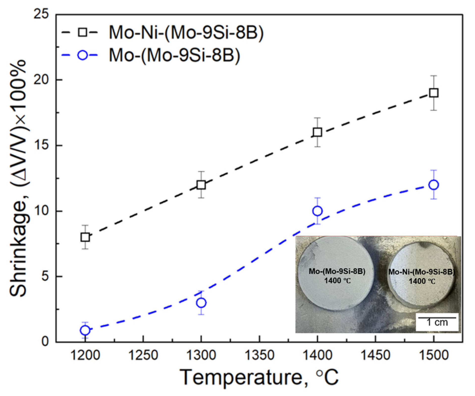
The addition of 1 wt.% of Ni to the mixture of 60 wt.% Mo—40 wt.% (Mo-9Si-8B) powder increases the kinetics of the PLS process in the temperature range between 1200 °C and 1500 °C of the composite: the shrinkage changes from 8 to 19%, while without the activator the shrinkage is in the range of 0.9–12%.
(2)
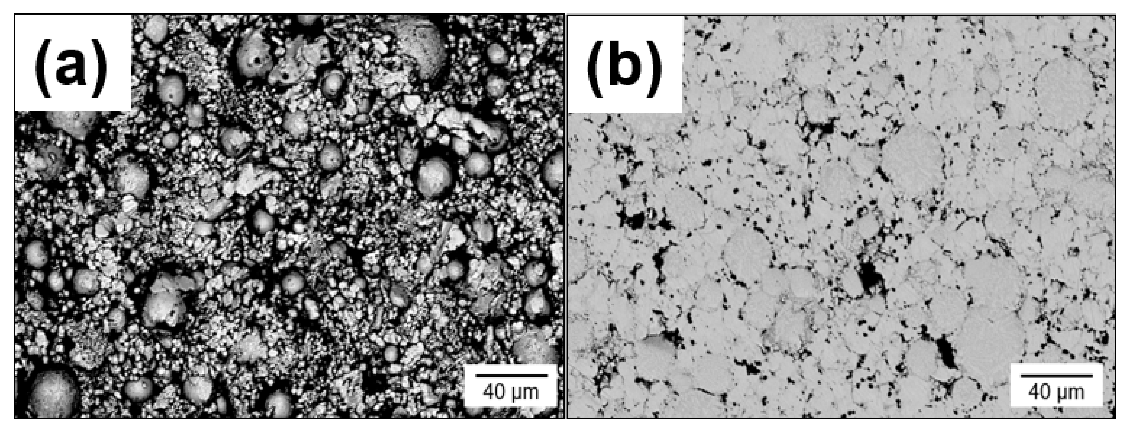
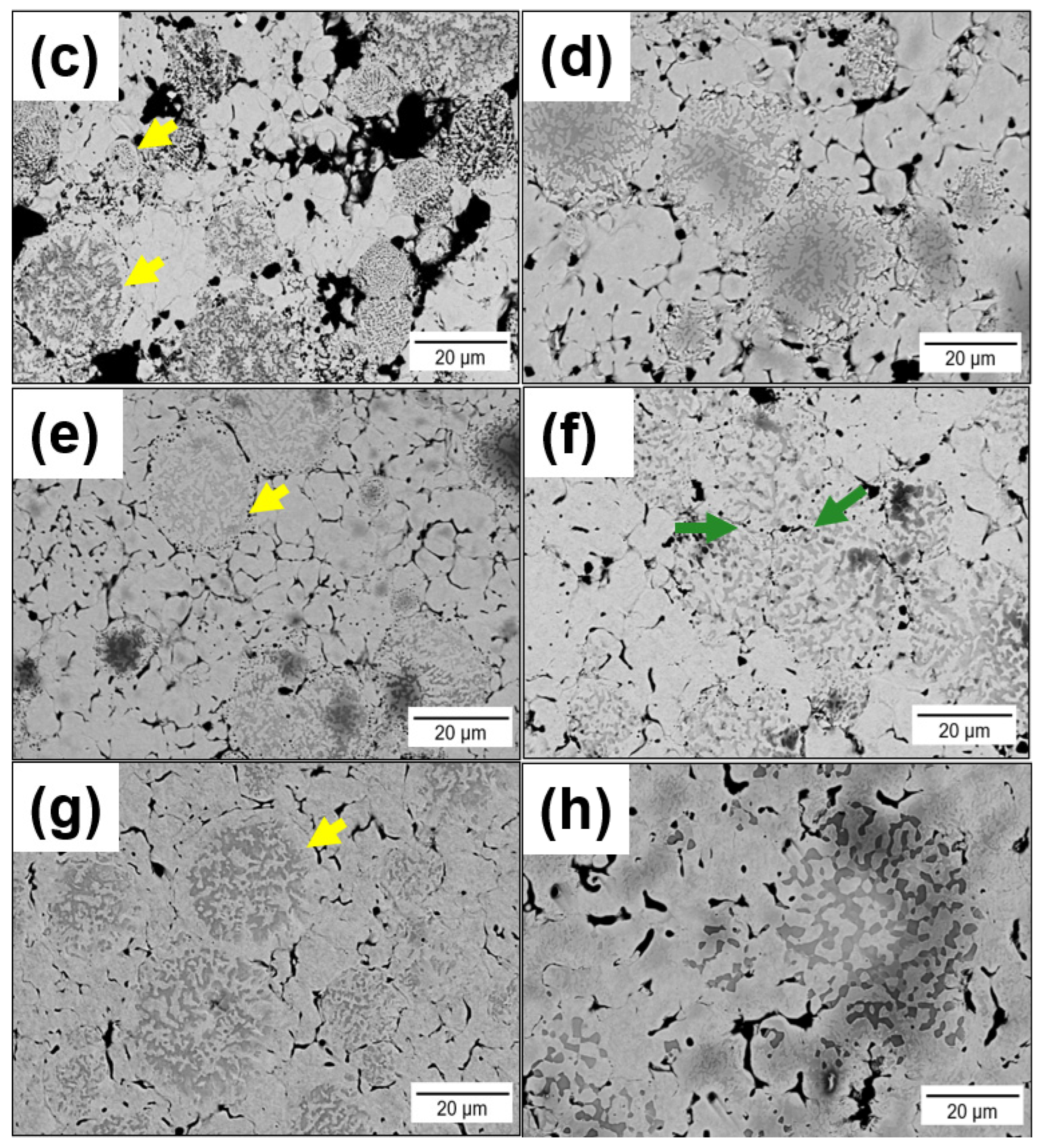
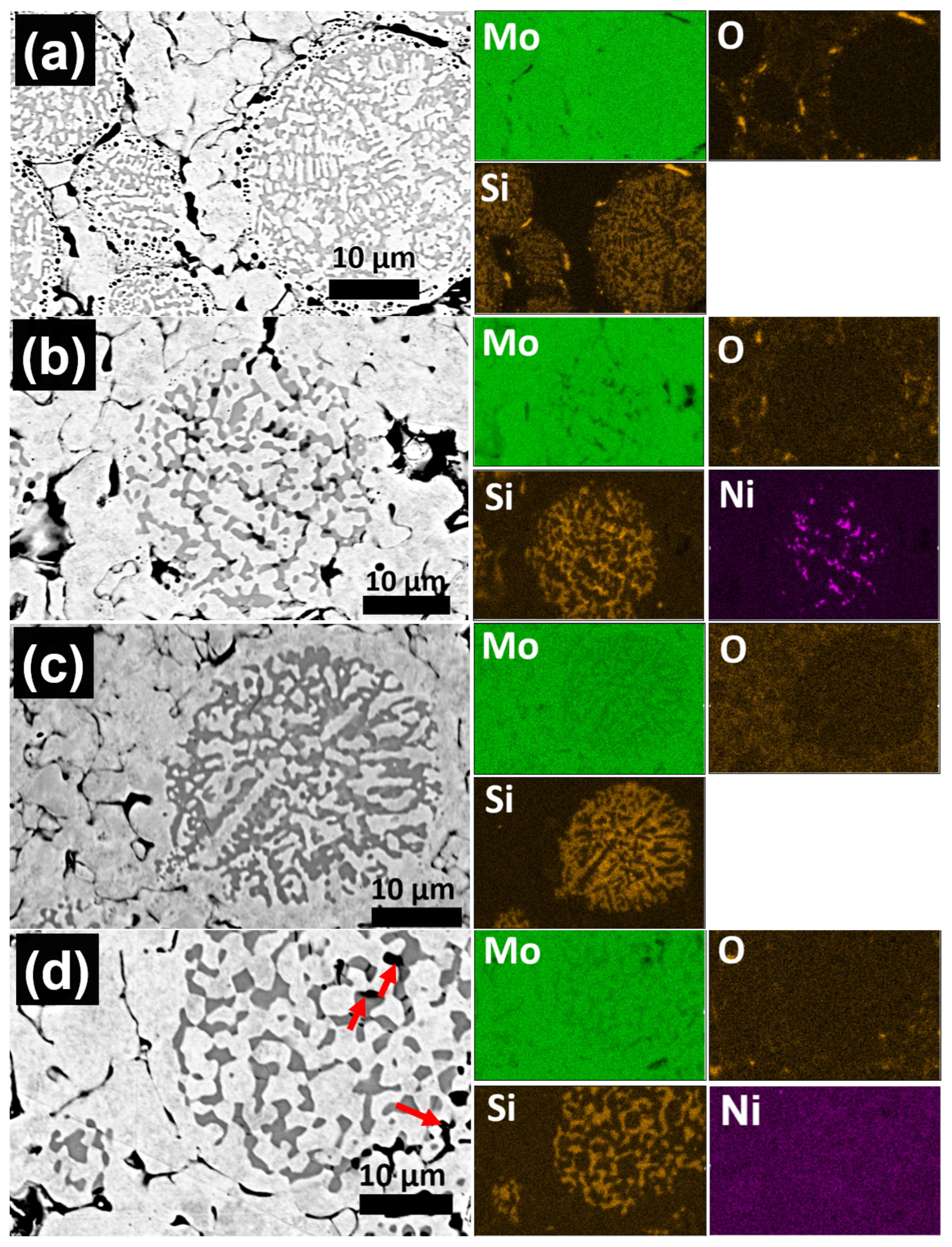
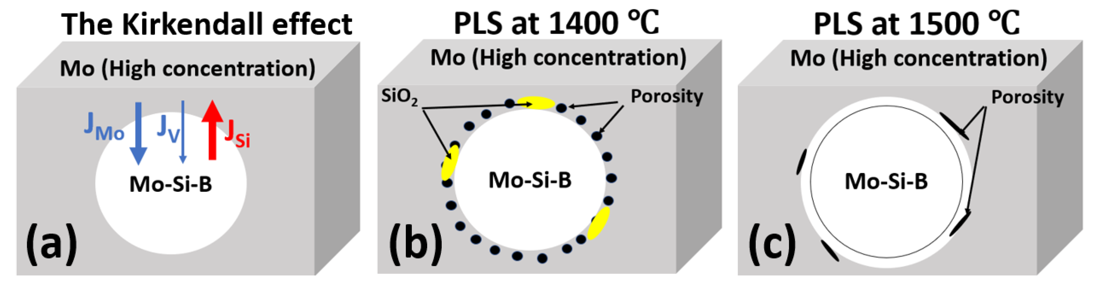
During PLS at temperatures between 1200–1400 °C, a significant Kirkendall effect occurs in the composite Mo-(Mo-9Si-8B), which leads to the formation of porosity at the interface between the Mo matrix and Mo-9Si-8B particles.
(3)
The addition of 1 wt.% Ni increases the diffusion rate of Mo both in the matrix and in the Mo-9Si-8B particles, which reduces the influence of the Kirkendall effect at a sintering temperature of 1400 °C. Moreover, there is no diffusion of Si from the volume of Mo-9Si-8B particles to their surface with the subsequent formation of silicon oxide.
(4)
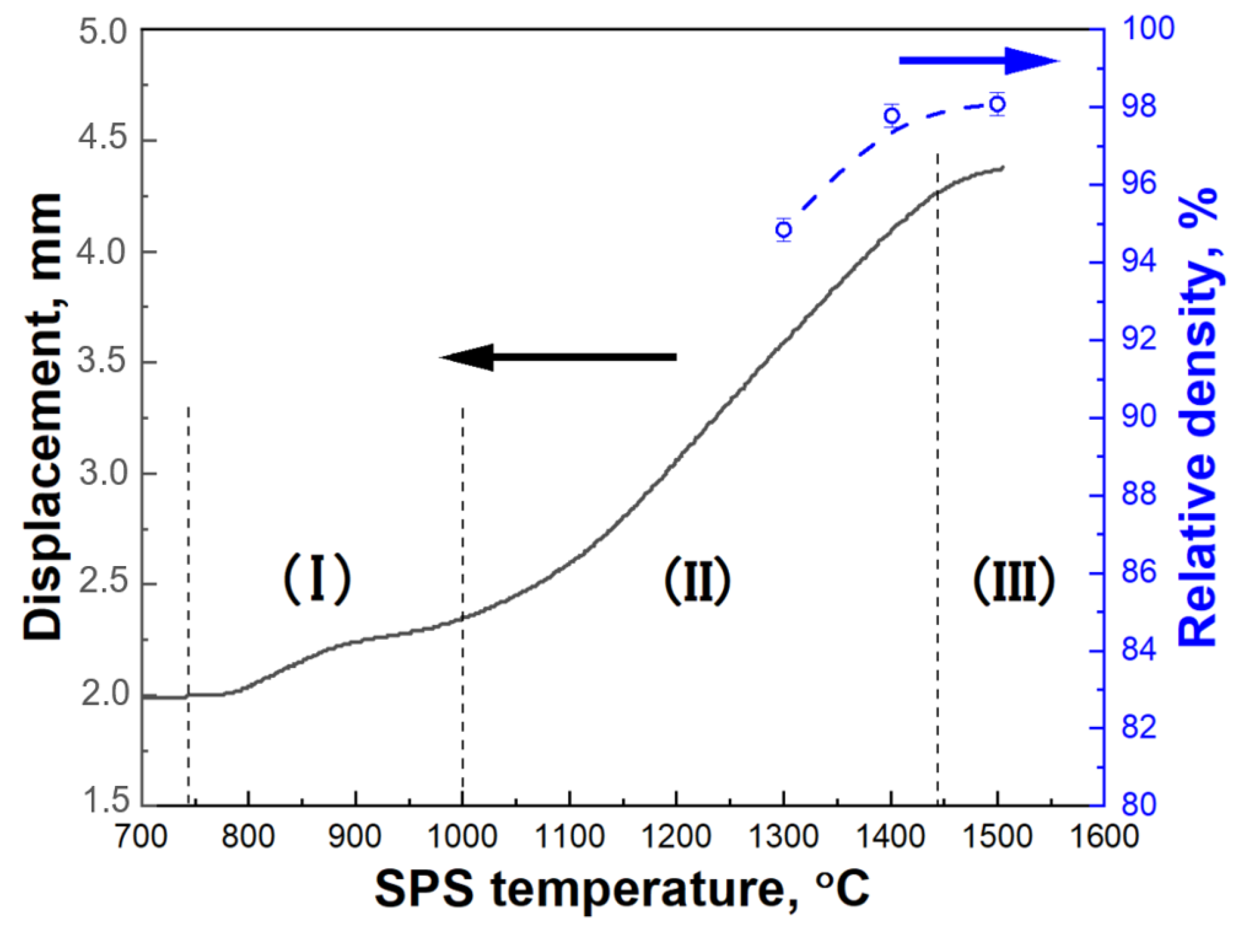
It is possible to fabricate the high-density Mo matrix composites by PLS by increasing the sintering temperature and/or holding time.
(5)
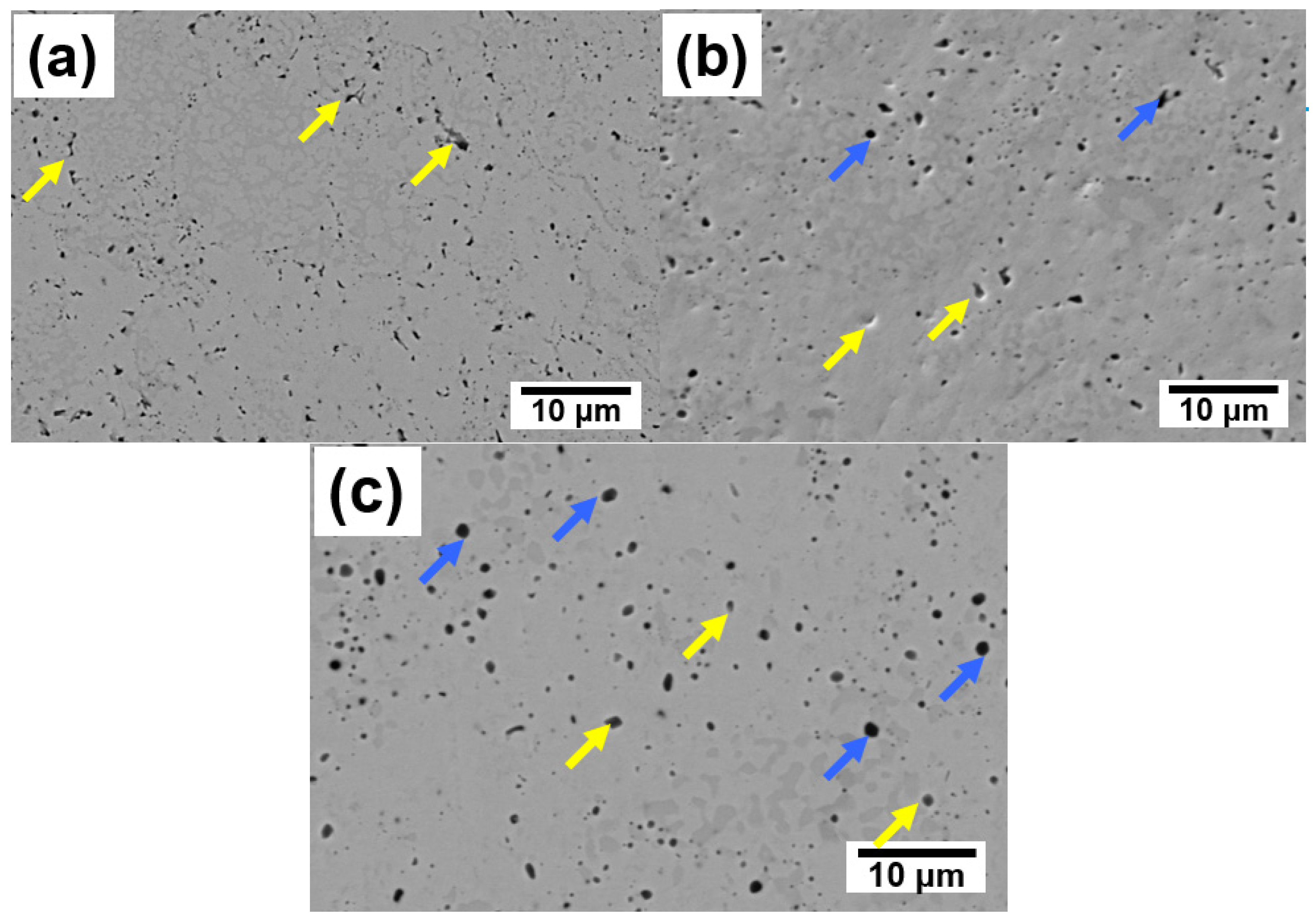
The use of SPS at temperatures of 1300–1500 °C allows to obtain high-density composites with a relative density of 95–98%. At the same time, no changes in the phase composition and formation of carbides are observed. A small amount of fine silica is formed at sintering temperatures of 1400 °C and 1500 °C.
(6)
Comparison of the relative density of the sintered composites with data from the literature indicates a positive effect of activated Ni sintering, since the relative density is several percent higher, while the sintering temperature was significantly lower [30].
(7)
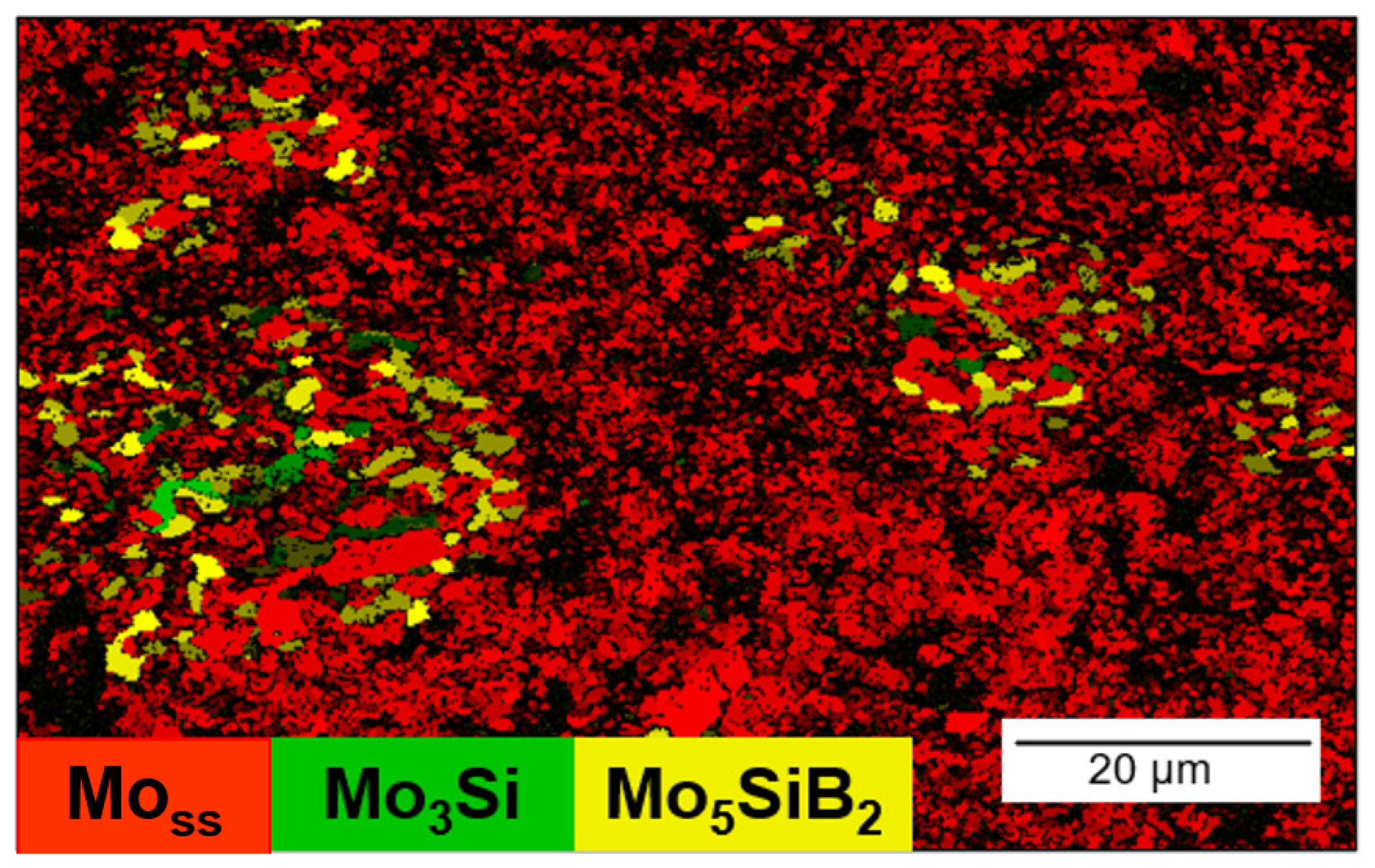
The result of Ni-activated PLS of MMC indicates the prospects of this approach for solving two problems: (1) obtaining samples with lower residual porosity and (2) obtaining a continuous Mo matrix with Mo3Si and Mo5SiB2 inclusions. Moreover, the Ni-activated SPS of MMC allowed us to obtain a high-density and homogeneous structure. Therefore, further work could be aimed at obtaining high-density samples by PLS and SPS methods for further measurement of mechanical characteristics and oxidation resistance of MMC.

Author Contributions

Conceptualization, I.S. and M.K.; methodology, I.S., V.P., G.H., J.S., U.B. and P.B. and M.A.G.; investigation, I.S., V.P. and U.B.; resources, P.B. and M.K; writing—original draft preparation, I.S.; writing—review and editing, I.S. and M.K.; supervision, M.K. All authors have read and agreed to the published version of the manuscript.

Funding

The Federal Ministry of Education and Research (BMBF) funded the project “Optimized Powder Metallurgy Solutions for Metallic High-temperature Materials (OPOS)”, funding grant number 01DK20072, which mostly contributed to the results presented in this paper. I.S. acknowledges support from the Philipp Schwartz Initiative of the Alexander von Humboldt Foundation. Support from the DFG, German Research Foundation, as part of the “Major Research Instrumentation Program” is gratefully acknowledged (grant INST 272/281-1 FUGG; Bruker D8 Discover XRD). I.S. acknowledges support from the Philipp Schwartz Initiative of the Alexander von Humboldt Foundation. P.B. and M.G. acknowledge the financial support from UEFISCDI through Core Program PC2-PN23080202.

Data Availability Statement

Not applicable.

Conflicts of Interest

The authors declare no conflict of interest. The funders had no role in the design of the study; in the collection, analyses, or interpretation of data; in the writing of the manuscript; or in the decision to publish the results.

References

  1. Jiang, L.; Zheng, B.; Wu, C.; Li, P.; Xue, T.; Wu, J.; Han, F.; Chen, Y. A Review of Mo-Si Intermetallic Compounds as Ultrahigh-Temperature Materials. Processes 2022, 10, 1772. [Google Scholar] [CrossRef]
  2. Yamaguchi, M.; Inui, H.; Ito, K. High-temperature structural intermetallics. Acta Mater. 2000, 48, 307–322. [Google Scholar]
  3. Seif, E.; Rösler, J. Reassessment of the Matrix Composition of Co-Re-Cr-Based Alloys for Particle Strengthening in High-Temperature Applications and Investigation of Suitable MC-Carbides. Materials 2023, 16, 4443. [Google Scholar] [CrossRef] [PubMed]
  4. Malcharcziková, J.; Skotnicová, K.; Kawulok, P.; Kawulok, R.; Szurman, I.; Růžička, J. Preparation and Properties of Directionally Solidified Ni-Al Based Alloys Modified by Molybdenum. Crystals 2022, 12, 215. [Google Scholar] [CrossRef]
  5. Wang, S.; Wang, L.; Meng, F.; Yu, H.; Sun, D. Quantitative study on Ru local atomic structure in Ni-Al-Ru ternary alloys. J. Alloys Compd. 2022, 909, 164766. [Google Scholar] [CrossRef]
  6. Krüger, M.; Franz, S.; Saage, H.; Heilmaier, M.; Schneibel, J.H.; Jéhanno, P.; Böning, M.; Kestler, H. Mechanically alloyed Mo-Si-B alloys with a continuous alpha-Mo matrix and improved mechanical properties. Intermetallics 2008, 16, 933–941. [Google Scholar] [CrossRef]
  7. Pan, K.; Yang, Y.; Wei, S.; Wu, H.; Dong, Z.; Wu, Y.; Wang, S.; Zhang, L.; Lin, J.; Mao, X. Oxidation behavior of Mo-Si-B alloys at medium-to-high temperatures. J. Mater. Sci. Technol. 2021, 60, 113–127. [Google Scholar] [CrossRef]
  8. Parthasarathy, T.A.; Mendiratta, M.G.; Dimiduk, D.M. Oxidation mechanisms in Mo-reinforced Mo5SiB2(T-2)-Mo3Si alloys. Acta Mater. 2002, 50, 1857–1868. [Google Scholar] [CrossRef]
  9. Lemberg, J.A.; Ritchie, R.O. Mo-Si-B alloys for ultrahigh-temperature structural applications. Adv. Mater. 2012, 24, 3445–3480. [Google Scholar] [CrossRef]
  10. Perepezko, J.H. The Hotter the Engine, the Better. Science 2009, 326, 1068–1069. [Google Scholar] [CrossRef]
  11. Krüger, M.; Jain, P.; Kumar, K.S.; Heilmaier, M. Correlation between microstructure and properties of fine grained Mo–Mo3Si–Mo5SiB2 alloys. Intermetallics 2014, 48, 10–18. [Google Scholar] [CrossRef]
  12. Majumdar, S.; Dönges, B.; Gorr, B.; Christ, H.-J.; Schliephake, D.; Heilmaier, M. Mechanisms of Oxide Scale Formation on Yttrium-Alloyed Mo–Si–B Containing Fine-Grained Microstructure. Corros. Sci. 2015, 90, 76–88. [Google Scholar] [CrossRef]
  13. Yakang, K.; Wang, C.; Chen, X.; Qu, Y.; Yu, J.; Ju, H.; Yilei, X. Review of Research Progress on Mo–Si–B Alloys. Materials 2023, 16, 5495. [Google Scholar] [PubMed]
  14. Schneibel, J.H. High temperature strength of Mo-Mo3Si-Mo5SiB2 molybdenum silicides. Intermetallics 2003, 11, 625–632. [Google Scholar] [CrossRef]
  15. Schneibel, J.; Kramer, M.; Easton, D. A Mo–Si–B intermetallic alloy with a continuous α-Mo matrix. Scr. Mater. 2002, 46, 217–221. [Google Scholar] [CrossRef]
  16. Becker, J.; Breuer, D.; Bogomol, I.; Krüger, M. Enhanced Fracture Toughness and High-Temperature Strength of Directionally Solidified Mo-XC Alloys. Crystals 2022, 12, 1534. [Google Scholar] [CrossRef]
  17. Xing, H.; Hu, P.; He, C.; Zhang, X.; Han, J.; Yang, F.; Bai, R.; Zhang, W.; Wang, K.; Volinsky, A.A. Design of high-performance molybdenum alloys via doping metal oxide and carbide strengthening: A review. J. Mater. Sci. Technol. 2023, 160, 161–180. [Google Scholar]
  18. Baroch, E.F.; Ostermann, M.; Patrick, G. Applications of powder metallurgy molybdenum in the 1990s. Adv. Powder Metall. 1991, 5, 321–331. [Google Scholar]
  19. Deschamps, I.S.; dos Santos Avila, D.; Vanzuita Piazera, E.; Dudley Cruz, R.C.; Aguilar, C.; Klein, A.N. Design of In Situ Metal Matrix Composites Produced by Powder Metallurgy—A Critical Review. Metals 2022, 12, 2073. [Google Scholar]
  20. Panichkina, V.V.; Skorohod, V.V.; Khrienko, A.F. Activated sintering of tungsten and molybdenum powders. Sov. Powder Metall. Met. Ceram. 1967, 6, 558–560. [Google Scholar] [CrossRef]
  21. Smith, J.T. Diffusion Mechanism for the Nickel-Activated Sintering of Molybdenum. J. Appl. Phys. 1965, 36, 595–598. [Google Scholar] [CrossRef]
  22. Mouawad, B.; Soueidan, M.; Fabrègue, D.; Buttay, C.; Bley, V.; Allard, B.; Morel, H. Full Densification of Molybdenum Powders Using Spark Plasma Sintering. Metall Mater Trans A. 2012, 43, 3402–3409. [Google Scholar] [CrossRef]
  23. Flem, M.L.; Allemand, A.; Urvoy, S.; Cédat, D.; Rey, C. Microstructure and thermal conductivity of Mo–TiC cermets processed by hot isostatic pressing. J. Nucl. Mater. 2008, 380, 85–92. [Google Scholar] [CrossRef]
  24. German, R.M.; Munir, Z.A. Heterodiffusion model for the activated sintering of molybdenum. J. Less-Common. Met. 1878, 58, 61–74. [Google Scholar] [CrossRef]
  25. Hwang, K.S.; Huang, H.S. Identification of the segregation layer and its effect on the activated sintering and ductility of Ni-doped molybdenum. Acta Mater. 2003, 51, 3915–3926. [Google Scholar] [CrossRef]
  26. Smigelskas, A.D.; Kirkendall, E.O. Zinc Diffusion in Alpha Brass, Trans. AIME 1947, 17, 130–142. [Google Scholar]
  27. Askill, J. Tracer Diffusion Data for Metals, Alloys, and Simple Oxides; Plenum Press: New York, NY, USA, 1970. [Google Scholar]
  28. Lee, G.; Manière, C.; McKittrick, J.; Gattuso, A.; Back, C.; Olevsky, E.A. Oxidation effects on spark plasma sintering of molybdenum nanopowders. Am. Ceram. Soc. 2019, 102, 801–812. [Google Scholar] [CrossRef]
  29. Chen, Y.; Zhang, R.; Hao, Z.; Shu, Y.; He, J. Study on reduction of MoO2 by carbon diffusion to prepare molybdenum powder. J. Today Commun. 2023, 35, 105643. [Google Scholar] [CrossRef]
  30. Ohser-Wiedemann, R.; Martin, U.; Seifert, H.J.; Müller, A. Densification behaviour of pure molybdenum powder by spark plasma sintering. Int. J. Refract. Hard Met. 2010, 28, 550–557. [Google Scholar] [CrossRef]
  31. Wen, S.H.; Zhou, C.G.; Sha, J.B. Improvement of oxidation resistance of a Mo-62Si-5B (at.%) alloy at 1250 °C and 1350 °C via an in situ pre-formed SiO2 fabricated by spark plasma sintering. Corros. Sci. 2017, 127, 175–185. [Google Scholar] [CrossRef]
Figure 1. Morphology of raw powder materials (SE images): (a) Mo, (b) gas atomized Mo-9Si-9B, (c) Ni.
Metals 13 01715 g001
Figure 2. Dependence of shrinkage on the PLS temperature of samples with Mo-Ni-(Mo-9Si-8B) and without Mo-(Mo-9Si-8B) addition of Ni as a sintering activator.
Metals 13 01715 g002
Figure 3. BSE SEM images of microstructures of Mo-(Mo-9Si-8B): (a) 1200 °C, (c) 1300 °C, (e) 1400 °C, (g) 1500 °C; and Mo-Ni-(Mo-9Si-8B): (b) 1200 °C, (d) 1300 °C, (f) 1400 °C, (h) 1500 °C sintered by PLS at different temperatures. Green arrows indicate the beginning of contact formation between spherical Mo-9Si-8B particles. Yellow arrows indicate Mo-rich layer with a rim structure which formed at the surface of Mo-9Si-8B particles.
Metals 13 01715 g003aMetals 13 01715 g003b
Figure 4. EBSD scan of Mo-Ni-(Mo-9Si-8B) samples sintered by PLS at 1500 °C.
Metals 13 01715 g004
Figure 5. BSE SEM-EDS mapping: (a) Mo-(Mo-9Si-8B) sample PLSed at 1400 °C, (b) Mo-Ni-(Mo-9Si-8B) sample PLSed at 1400 °C, (c) Mo-(Mo-9Si-8B) sample PLSed at 1500 °C, (d) Mo-Ni-(Mo-9Si-8B) sample PLSed at 1500 °C. Red arrows indicate residual porosity in the middle of the Mo-9Si-8B by the removal of Ni through evaporation.
Metals 13 01715 g005
Figure 6. Schematic representation of the structure formation during Mo-(Mo-9Si-8B) (ac) and Mo-Ni-(Mo-9Si-8B) (df) composite PLS.
Metals 13 01715 g006aMetals 13 01715 g006b
Figure 7. The punch displacement for SPS of Mo-Ni-(Mo-9Si-8B) sample and relative density of SPSed at different samples. Sections I, II, III indicate the stages of the shrinkage.
Metals 13 01715 g007
Figure 8. SE SEM images of microstructures of Mo-Ni-(Mo-9Si-8B) SPSed at different temperatures and isothermal holding time of 10 min: (a) 1300 °C, 10 min, (b) 1400 °C, (c) 1500 °C. Blue arrows indicate inclusions which characterized by silicon and oxygen according to SEM-EDS mapping (Figure 9). Yellow arrows indicate dark areas which probably be atributed to residual porosity after sintering.
Metals 13 01715 g008
Figure 9. BSE SEM-EDS mapping sample SPSed at 1500 °C. Blue arrows indicate inclusions which characterized by silicon and oxygen.
Metals 13 01715 g009
Table 1. Relative density of samples with Mo-Ni-(Mo-9Si-8B) and without Mo-(Mo-9Si-8B) addition of Ni as a sintering activator obtained by PLS.
TSPS, °CRelative
Density (%)
Mo-(Mo-9Si-8B)Mo-Ni-(Mo-9Si-8B)
120066 ± 2.176 ± 1.5
130071 ± 1.981 ± 1.6
140077 ± 1.786 ± 1.8
150082 ± 1.889 ± 1.8
Table 2. Vickers Hardness of MMC obtained by the SPS method.
TSPS, °CHV20
1300385 ± 8
1400435 ± 9
1500482 ± 9
Disclaimer/Publisher’s Note: The statements, opinions and data contained in all publications are solely those of the individual author(s) and contributor(s) and not of MDPI and/or the editor(s). MDPI and/or the editor(s) disclaim responsibility for any injury to people or property resulting from any ideas, methods, instructions or products referred to in the content.

