Article

Effect of Machine Hammer Peening Conditions on β Grain Refinement of Additively Manufactured Ti-6Al-4V

1
Welding and Additive Manufacturing Centre, Cranfield University, Cranfield MK43 0AL, UK
2
Department of Materials, University of Manchester, Manchester M13 9PL, UK
*
Author to whom correspondence should be addressed.
Now at Institut Jean Lamour, 54011 Nancy, France.
Metals 2023, 13(11), 1888; https://doi.org/10.3390/met13111888
Submission received: 11 October 2023 / Revised: 7 November 2023 / Accepted: 9 November 2023 / Published: 14 November 2023

Abstract

:
Ti-6Al-4V components built with wire plus arc additive manufacturing (WAAM) generally have long columnar β grains that cause anisotropic behavior when the material undergoes static and cyclic failure. Recently, machine hammer peening (MHP) has been proved to induce prior-β grain refinement in WAAM resulting in isotropic properties and increased strength. In this study, MHP was investigated for WAAM walls to establish the dependency of the β grain refinement on peening parameters, such as energy, tool radius, and distance between impact steps. All combinations of parameters investigated resulted in grain-refined microstructures. The plastic strain theory failed to explain these results, as the microstructure refinement achieved did not match the strain distribution obtained. Thus, a new theory of accumulated energy was proposed in which the dynamic deformation of the MHP process should also be taken into consideration. The mechanical properties for the MHP conditions showed higher strength and decreased anisotropy as the energy per length increased. This was attributed to the reduction in texture in the WAAM walls. Thus, when applying MHP, the energy per unit length is controlling the grain size obtained and improved mechanical properties can be achieved.

1. Introduction

Additive manufacturing (AM) processes offer near-net-shape manufacturing and a reduction in lead time [1]. Therefore, they are an appealing option for the manufacturing of expensive materials, such as the Ti-6Al-4V [2]. This α + β titanium alloy is widely used in various sectors such as biomedical, aerospace, defense, and energy, due to its unique properties. If offers great mechanical properties, high static and fatigue strength, specific strength, corrosion resistance, and biocompatibility. Thus, there is a high demand to produce components with Ti-6Al-4V that are usually manufactured with traditional methods (e.g., forging, casting, machining, among others). However, long lead times, and high material wastage and costs are limiting the applications titanium to wider activities [3,4,5]. To satisfy the need for medium to large manufacturing of titanium components (e.g., airframes), wire plus arc additive manufacturing (WAAM) is one of the most cost-effective options due to its high deposition rate (several kg/h), low equipment investment, and increased design flexibility for meter-long components [6]. However, due to the solidification conditions during AM processing of Ti-6Al-4V, highly textured coarse columnar prior-β grains are often observed in WAAM structures [7]. For WAAM, the β grains can be several centimeters long and extend through the entire height of the wall [8], and large detrimental single-variant α colonies nucleate at the prior-β grain boundaries, spanning much of their length in the build direction [9]. This results in anisotropic strength and elongation scatter in the material [10] as the α phase inherits the strong β texture [11], and the prior-β boundaries act as stress concentrators when loaded in a perpendicular orientation to their length [12]. Thus, equiaxed β grains should be achieved to eliminate these detrimental mechanical effects.
The control of process and thermal conditions would be ideal for in-process manipulation of grain structure for Ti-6Al-4V. Sequeira Almeida and Williams [13] demonstrated that smaller grains could be achieved by using the cold metal transfer (CMT) process, and Wang et al. [14] further demonstrated the same concept by increasing the wire feed speed above a certain threshold that cooled the melt pool and changed the solidification conditions. However, in both cases, grain refinement was achieved only for a very narrow range of processing conditions, limiting their application when building WAAM components. Alloying by adding nucleant particles into the melt pool is another method for microstructure control during deposition which can refine grains. Promising results have been achieved by adding nucleant particles La2O3 [15], and carbon [16]. Bermingham et al. [17] also achieved solutal growth restrictions by adding boron and more recently, Kennedy et al. [18] further showed that TiN particles are highly effective for microstructural refinement. However, the wide application of new titanium alloys relies on a challenging qualification process for a feasible industrial application and requires accurate particle concentration calibration for a homogeneous microstructure through the build. Furthermore, the additional elements would hinder the recycling process of Ti-6Al-4V by adding complexity and restricting its use. Mechanical work, particularly cold rolling, has proved to be an effective method for obtaining equiaxed β grains [6,19]. Cold rolling consists of deforming the material using a roller with a specific load. When applied between each deposited layer, equiaxed β grains and reductions in α lamellae thickness are obtained, with strains between ~8% and 20% [6]. Donoghue et al. [20] correlated the plastic strain distribution with the grain refinement achieved. It was proposed that the application of plastic deformation generates new β orientations through annealing twinning, in which new β orientation grew from the faults induced in the deformed lamellar microstructure during the α-β transformation upon reheating. A recent publication by Donoghue et al. [21] further strengthened this theory. Although cold rolling has been proven to be an effective method to induce grain refinement, it requires a stiff gantry to apply loads up to 100 kN, which is costly and limits the design freedom of WAAM [19]. Thus, peening was suggested as an alternative, to regain the design freedom, at the cost of a reduced applied load. This leads to concerns about its possible applications as the plastic strain induced might not be sufficient for grain refinement [20].
Machine Hammer Peening (MHP) consists of an oscillating tool insert with a defined frequency that impacts the material and deforms it [22]. The tool can be easily used with a robotic arm, which offers the possibility of applying cold work to potentially any geometry [23]. Inter-pass MHP was first studied by Byun et al. [24]. An average β grain size of 460 µm was obtained, and the α laths size decreased by ~40% from the as deposited condition, which increased the mechanical properties. However, it is not clear how this effect was achieved and how it can be controlled. It is known that the inter-pass temperature affects the properties and the α laths thickness which may have been the cause, unrelated to the MHP process [25]. Neto et al. [26] obtained similar mechanical properties to the previous study and achieved β grain refinement for thick deposited structures (>15 mm), further demonstrating the possibility of applying MHP to several WAAM geometries. However, the β grain size varied from ~1 to 2 mm, which is considerably larger than the previous study. Hönnige et al. [27] observed that the depth of plastic strain obtained for MHP was less than the re-melting depth of the subsequent layer. Thus, the peening effect should be eliminated during deposition, as predicted by Donoghue et al. [20]. However, this was not observed in the experiments, where grains are refined despite the lower depth of strain than remelting. Hönnige et al. [28] carried out a time-resolved observation of the grain structure for inter-pass MHP. It was found that β recrystallization appeared ahead of the melt pool and, as the melt pool moved forward, grain growth would occur to a deeper depth than the re-melting depth and survive the re-melting process. This theory potentially explains why grain refinement was achieved for different geometries tested with inter-pass MHP (single-pass and oscillated walls [26]) and opens the possibility for a wider scope of applications.
Most of the work in MHP concerns improvement of fatigue life, corrosion, and wear resistance. The quantification of residual stresses, work hardening, roughness, and microstructural changes are the most often quantified aspects by changing the energy, distance between impacts, and tool radius of the peening process, as reviewed by Schulze et al. [29]. Conclusions taken from these studies are challenging to correlate for inter-pass MHP applications as the amount of deformation or plastic strain induced to the material is not considered. Also, surface modification methods typically use a large tool radius and low impact energy to obtain smooth surfaces [30], which is not necessarily the goal for inter-pass MHP application to WAAM. The present study aims to evaluate the influence of parameters, such as tool radius, distance between impacts and impact energy on the prior-β grain structure for inter-pass MHP. The tensile properties are also evaluated, to link the MHP parameters with the response of the material.

2. Materials and Methods

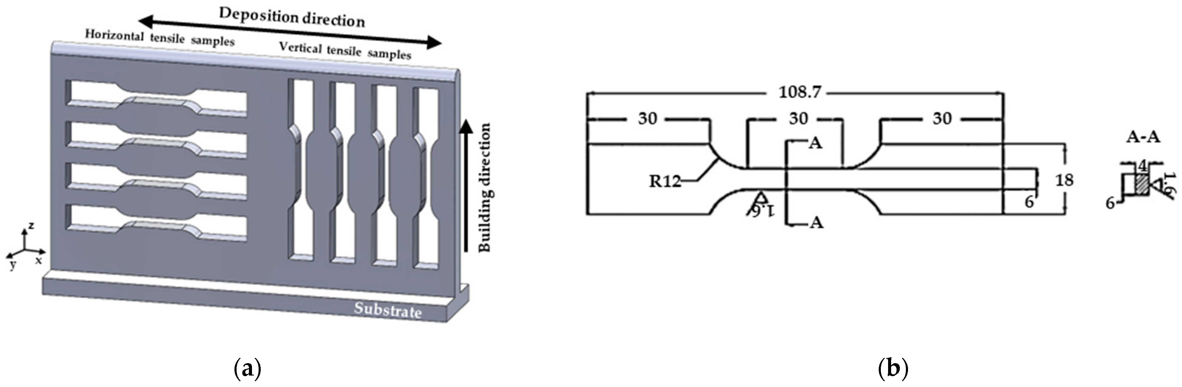
2.1. Deposition Procedure

To build a series of WAAM Ti-6Al-4V walls, an EWM T552 Tetrix Plasma power source was used to melt 1.2 mm diameter wire with the chemical composition shown in Table 1. The substrates used were of the same alloy and were cut to the dimensions of 66 × 310 × 8 mm. A local shielding device [31] was used to prevent oxidation of the molten material with a gas flow rate of 70 L/min of pure-shield argon (99.99%) (Figure 1a). After each layer of deposition, this device was not moved from the wall until the material was below the oxidation contamination temperature of 550 °C (maximum of 20 s, varying with the deposition height). The inter-pass temperature was also controlled and measured with a touch probe and kept at approximately 110 °C.
Single-pass walls were deposited to 15 layers high for a length of 285 mm and two different MHP conditions were tested in the same wall on separate 100 mm sections on either end of the wall, leaving 85 mm for the study of the as deposited condition, i.e., without any peening (Figure 1b). The deposition parameters are shown in Table 2 and the deposition direction (x-axis) is reversed after each deposited layer to guarantee the compensation of the deposit ends and avoid collapse. Four walls were deposited up to 130 mm in height (approximately 110 layers), and 315 mm in length with the goal of extracting tensile test coupons for the as deposited condition and peened conditions, highlighted with “*” in Table 3. The substrates used for these were 350 × 90 × 8 mm in size.

2.2. Machine Hammer Peening Procedure

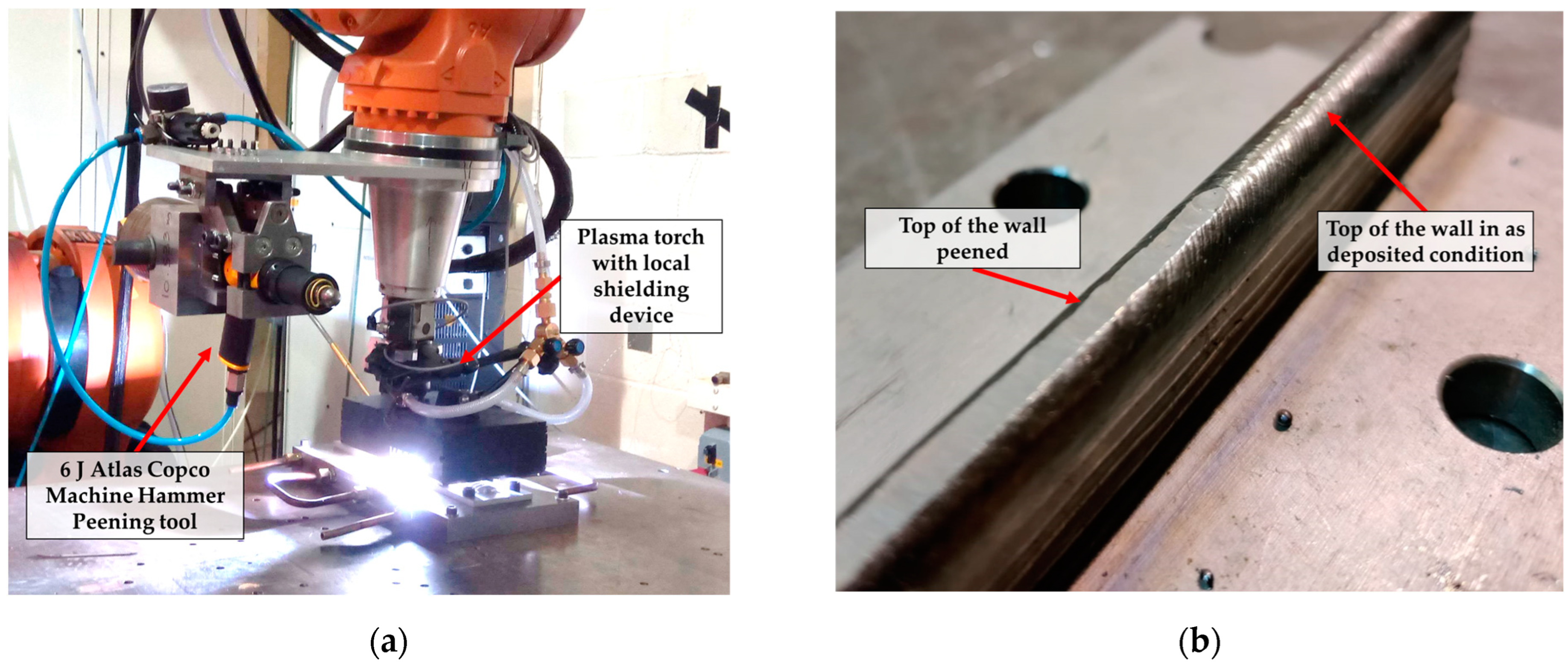
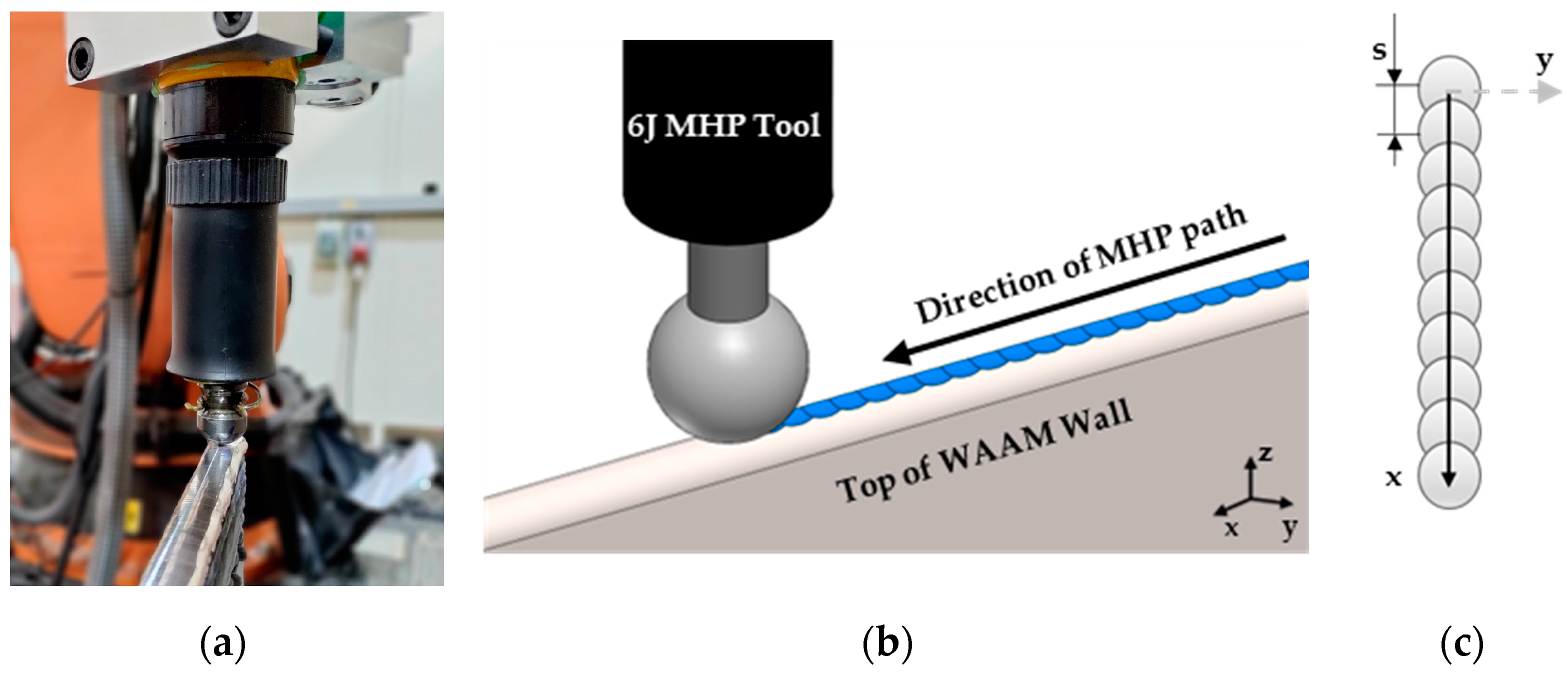
2.2.1. Experimental Setup and Parameters

To apply inter-pass MHP, the set-up was designed to only use one robotic arm for both deposition and peening. After each deposited layer, the robotic arm would rotate 90 degrees in the x–z axis allowing the vertical position of the MHP tool. Once the peening step is concluded, the robot can rotate back to its initial position and carry on depositing the subsequent layer. This procedure is repeated until the desired height of the walls was achieved [26]. The inter-pass MHP temperature was also kept constant at an average value of 150 °C.
During this parametric study, MHP was applied with two different energy tools. An ECOPeen-C tool is an electro-driven tool developed by ECOROLL AG (Celle, Germany), which has a maximum impact energy (IE) of 0.7 J with a frequency (f) of 225 Hz. It has proven to be very suitable for WAAM applications, as it has a 4 mm stroke that allows the tool to adapt to the slightly uneven surfaces from deposition. The second tool tested is a pneumatic riveting tool designed by Atlas Copco (Hemel Hempstead, UK) that has an impact energy of 6 J with a frequency of 36 Hz. As this tool is intended to be handheld, a robotic holder was designed to guarantee that the tool insert was always in contact with the workpiece and behaved as if manually operated. The holder design allowed a stroke of up to 50 mm. Furthermore, the tool radius provided by the tool manufacturer was a flat surface. To carry out the parametric study, additional tools with the radius (R) varying from 25 to 4 mm were manufactured. Notably, the frequency and impact energy values are given by the tool manufacturers and were not measured in the scope of the present work.
A single MHP line path was used for all the walls as shown in Figure 2a. The distance between subsequent individual impacts in one line is named step distance (s), and it is defined by the frequency (f) of the tool and travel velocity (v) of the robot by f = v/s, shown in Figure 2b. All the MHP parameters tested are shown in Table 3.
Radiuses of 6 and 4 mm (R6 and R4) have been tested in the present work, but two practical problems emerged. R6 had a high sensitivity to the curvature of the top of the wall. When the peening motion started the tool slipped and impacted the wall on the side (Figure 3a). For R 4, the radius proved to be too small and produced very deep deformations on the material, which caused the insert to become stuck in the material and prevented it from moving forward (Figure 3b). Therefore, only effects of the radius above 6 mm are reported in this paper.

2.2.2. Characterization of Material Response to Machine Hammer Peening

To normalize the two energies used for this study, quantification of impact energy (IE) per unit length was defined by the following equation:
E n e r g y   p e r   u n i t   l e n g t h J / m m = f v × I E = 1 s × I E
where energy per unit length (EPL) corresponds to a single line MHP path, and the significance of step distance with the impact energy of the tool can be evaluated.

2.3. Material Characterisation and Testing

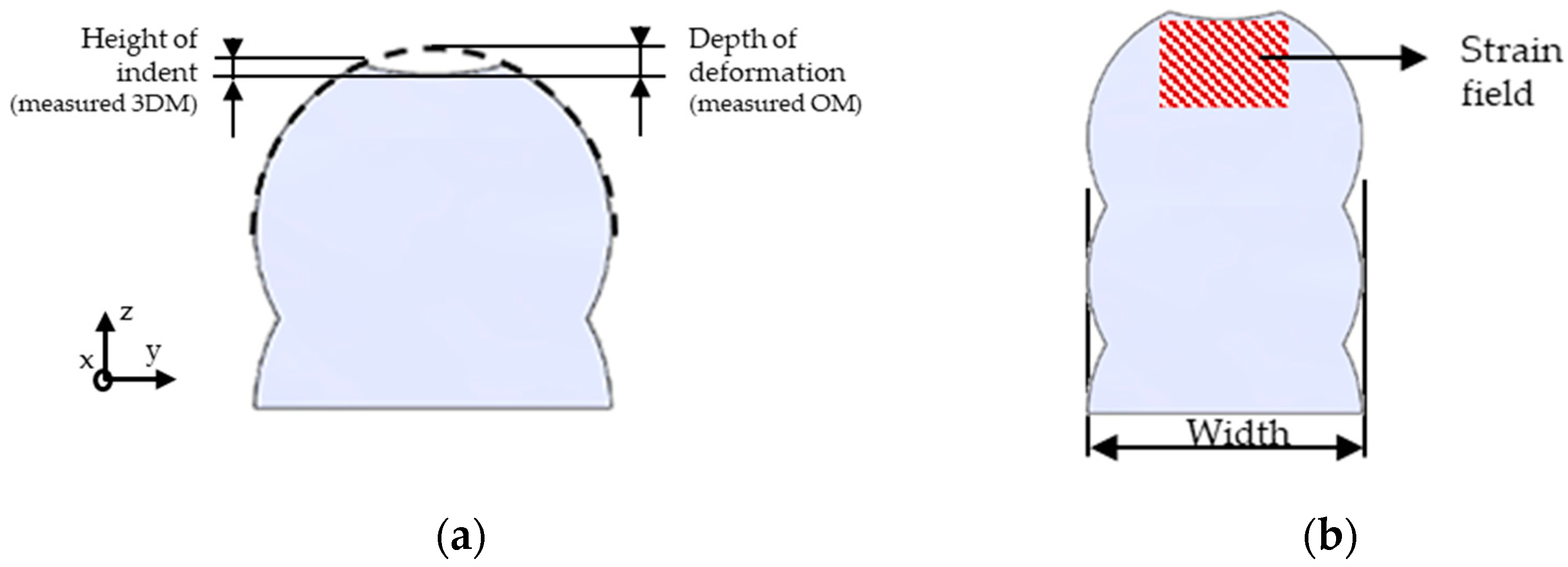
2.3.1. Evaluation of Macrostructure and Shape Alteration

For each condition tested, one section along the Y–Z plane (cross-section) was hot mounted and polished to a mirror-like finish. All sections were extracted from the middle of the wall length of each condition to guarantee that a stable deposition and peening process was examined. For IE6_R10_s4 and IE0.7_R10_s0.5, a section along the X–Z axis (longitudinal section) was also mounted in the middle of the thickness of the sample. These were taken from the top of the wall to approximately 10 layers of deposition, for which the height changed slightly for each MHP condition due to deformation. For metallographic analysis, etching with a diluted hydrofluoric acid solution was used until the macrostructure of the alloy was visible (approximately 10 s) and analyzed in an optical microscope (OM).
To quantify macrostructural changes induced by MHP, the β grain size was quantified by applying the mean linear intercept method to four different macrographs at different heights of each sample equally spaced. The grains of the first five layers of each wall were not measured due to the heat sinking influence of the substrate that affects the resulting macrostructure [6]. For the average values, 95% confidence intervals were given, considering four micrographs that were analyzed. To quantify the α lamellae thickness, the mean linear intercept method was used for 12 scanning electron microscope (SEM) images located in between the Heat Affect Zone (HAZ) bands to guarantee uniform quantification of the α size.
During the experimental work, assessing the layer height change between each deposited and peened pass proved challenging due to its minimal difference and the complexity of considering the concave deformed area beneath the peened surface (Figure 4). As an alternative, the 3D microscope (3DM) Hirox 2500 × (Tokyo, Japan) was employed to evaluate the deformed contact area and displacement volume resulting from MHP. The top wall bead was scanned, allowing for measurements of the indent’s width, length, and depth of deformation. However, it is important to note that the depth of deformation, as determined by this method, does not represent the height difference in the wall before and after peening. In cases where the MHP indents overlapped, the depth was solely considered based on Figure 4a (3DM depth of deformation). To address this limitation, the depth of deformation was also evaluated using microscopic images of the cross-section (OM deformation depth). By extrapolating the profile of the wall prior to deformation and fitting the diameter of the bead curvature, the depth was measured until the bottom of the arc of the peening indent, as depicted in Figure 4a. Furthermore, to assess the variation in wall width between the as deposited and peened conditions, five width measurements were taken for accurate comparison. These were obtained by measuring the longest distance between both sides of the wall (Figure 4b) for different heights of the same cross-section. As 10 layers were considered, a measurement was made every 2 layers.

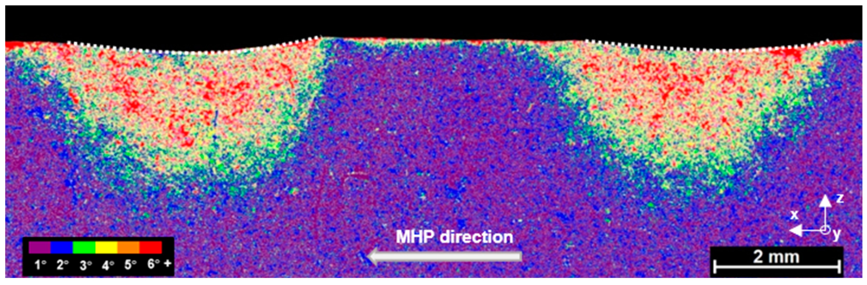
2.3.2. Use of Electron Backscatter Diffraction for Grain Size and Plastic Strain Measurement

As the grain refinement achieved by MHP is crucial to quantify the effectiveness of the parameters used, electron backscatter diffraction (EBSD) maps were carried out and compared with the OM measurements. Due to the large number of conditions tested, EBSD was only carried out for a few selected samples, as a validation method. The difference in the average grain diameter measurements between the OM and EBSD was approximately 15 to 3%, which was considered acceptable. To obtain the β grain size from the EBSD maps, a method for reconstruction of the β phase was carried out. Due to the limited and extremely fine residual β phase found in Ti-6Al-4V WAAM material [32], directly indexing it from EBSD data presents a significant challenge. Therefore, Davies et al. [33,34] developed a method (based on [35,36]) that allows the calculation of the parent β orientation for each α variant through the Burgers Orientation Relationship (BOR) [9] and determines the most likely prior β orientation for neighboring α-lath variants. In the present work, neighboring α were considered the same variant for misorientations of up to 2 ° and maximum angular deviation from the ideal BOR of up to 3 ° . The EBSD maps for this purpose were carried out using a Tescan Mira3 FEG-SEM (Kohoutovice, Czech Republic) with a 10–15 µm step size and a voltage of 20 kV. The system was equipped with a Symmetry 1 EBSD detector from Oxford Instruments and AZtec acquisition software (version 6.0). Grain size measurements were extracted from the EBSD maps using Channel 5and ATEX software (version 3.27) [37].
Further EBSD analysis was carried out to qualitatively measure the strain distribution induced by two individual peening impacts. A longitudinal section of the sample IE6_R10_s8 was prepared and the EBSD map was carried out with the equipment and conditions described in the previous paragraph. As the plastic strain is responsible for an increase in angular deviation of the α-laths from the ideal BOR to the β phase [38], by varying the maximum angular deviation from the BOR accepted during β reconstruction, from 1 ° to 6 ° , during post-processing of α EBSD data, and overlaying the resultant maps, a reliable qualitative representation of strain distribution was produced. Thus, large areas of strain can be mapped with large step size and relatively low resolution.
To quantify the magnitude and depth of strain for different peening strategies, EBSD maps with higher resolution and measurements with a step size of 2–2.5 µm were carried out. The local orientation data of the α-laths were used to calculate the average misorientation of neighboring α within an 11 × 11 kernel to produce LAM maps in Channel 5 software (version 5.0). A calibration method was used to convert LAM maps into a strain that is explained in detail elsewhere [39]. It is important to highlight that the maximum strain that can be determined by this method is 12% and the minimum is approximately 4%, due to the saturation and noise of the method, respectively. The strain field maps were captured in regions similar to the one represented in Figure 4b, and the captured areas varied depending on the geometry of the bead and MHP parameters. As the step size is smaller, the scanning time is significantly increased and consequently the map size is limited to more localized measurements.

2.3.3. Tensile Testing

Static tensile testing was carried out for both as deposited and inter-pass peened conditions highlighted in Table 3 following the BS EN 2002–1:2005 standard [40]. Four coupons were tested for both the vertical (along the building direction) and horizontal (along the deposition direction) directions, as shown in Figure 5. The dimensions of the coupons are shown in Figure 5b. During testing, an electromechanical Instron 5500R (High Wycombe, UK) frame was used with a load cell of 100 kN and strain rate of 1 mm/min.

3. Results

3.1. Microstructure

Prior-β grain refinement was achieved for all the inter-pass peened conditions. As shown in Figure 6, variation in grain size can be observed in the samples with different step distance, tool radius, and energy. Larger grains were obtained for the flat radius tool and for the larger step distance. It was observed that the two different energy tools can achieve the same grain size for very different conditions. These results will be further discussed in the following sections, isolating each parameter individually.

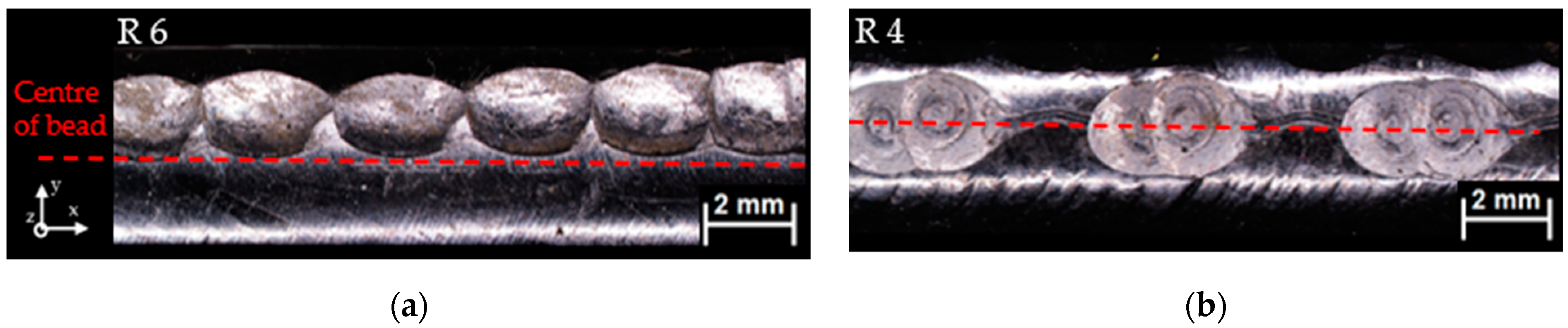
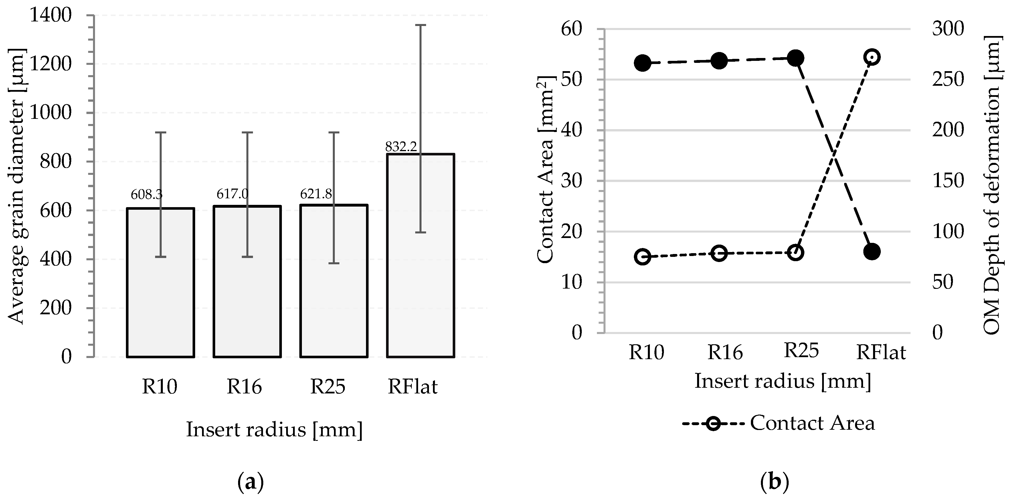
3.1.1. Varying Tool Radius

To determine the influence of the tool radius on the average grain diameter, depth of deformation, and indentation contact area, an impact energy of 6 J and step size of ~4 mm were used.
In Figure 7a, the grain size is larger for the R Flat condition when compared to R 25 to R 10. Figure 7b further shows that the contact area per impact is significantly greater for R Flat. This implies that the same amount of energy is spread across a larger area, leading to a more superficial depth of deformation of the material (Figure 8). Furthermore, when varying the radius from 25 and 10 mm, both the contact area and the depth of deformation are similar. Thus, the variation in grain size may be explained by the difference in energy distribution in the material and the resulting deformation. Notably, as the same amount of energy is applied, the total volume displaced is similar for all conditions and independent of the radius.

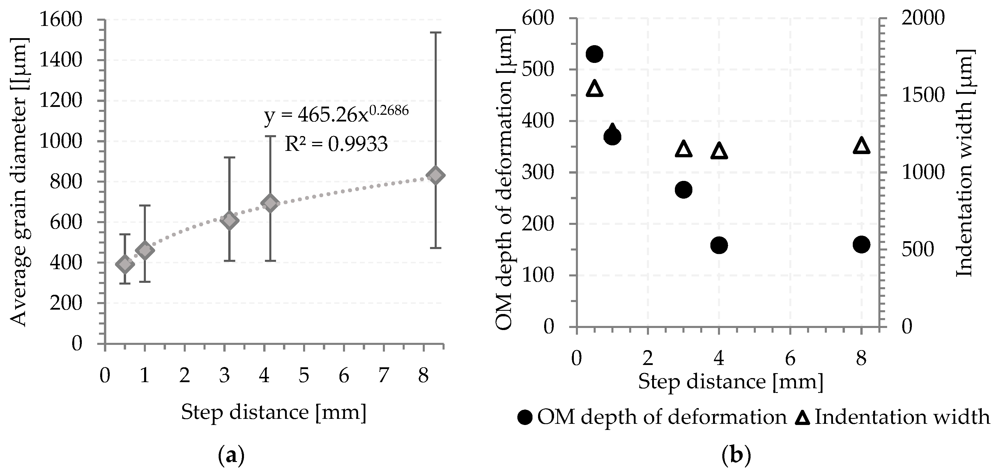
3.1.2. Varying Step Distance

When the energy and the radius are kept constant at 6 J and 10 mm, respectively, the overlap between impacts can be changed by varying the step distance, i.e., the speed of the robot for a fixed frequency of the tool.
Figure 9a shows that the grain diameter increases with greater step distance. When the step distance is larger, the material is becoming less impacted. For large step distances (8 and 4 mm), there is no cumulative effect on the depth of deformation or width, because the indentation from the second step is not influenced by the previous impact, i.e., they are isolated impacts. However, looking at the grain size, the grains are still considerably smaller for the 4 mm step distance than for the 8 mm. Considering the longitudinal plane, even if they are isolated impacts, there will be more plastic deformation applied in the material. When considering 3 mm step distance, there is only a small overlap between indents which resulted in a deeper penetration without significantly altering the indentation width. As the step distance is decreased, both the depth of deformation and the width increase (Figure 9b).

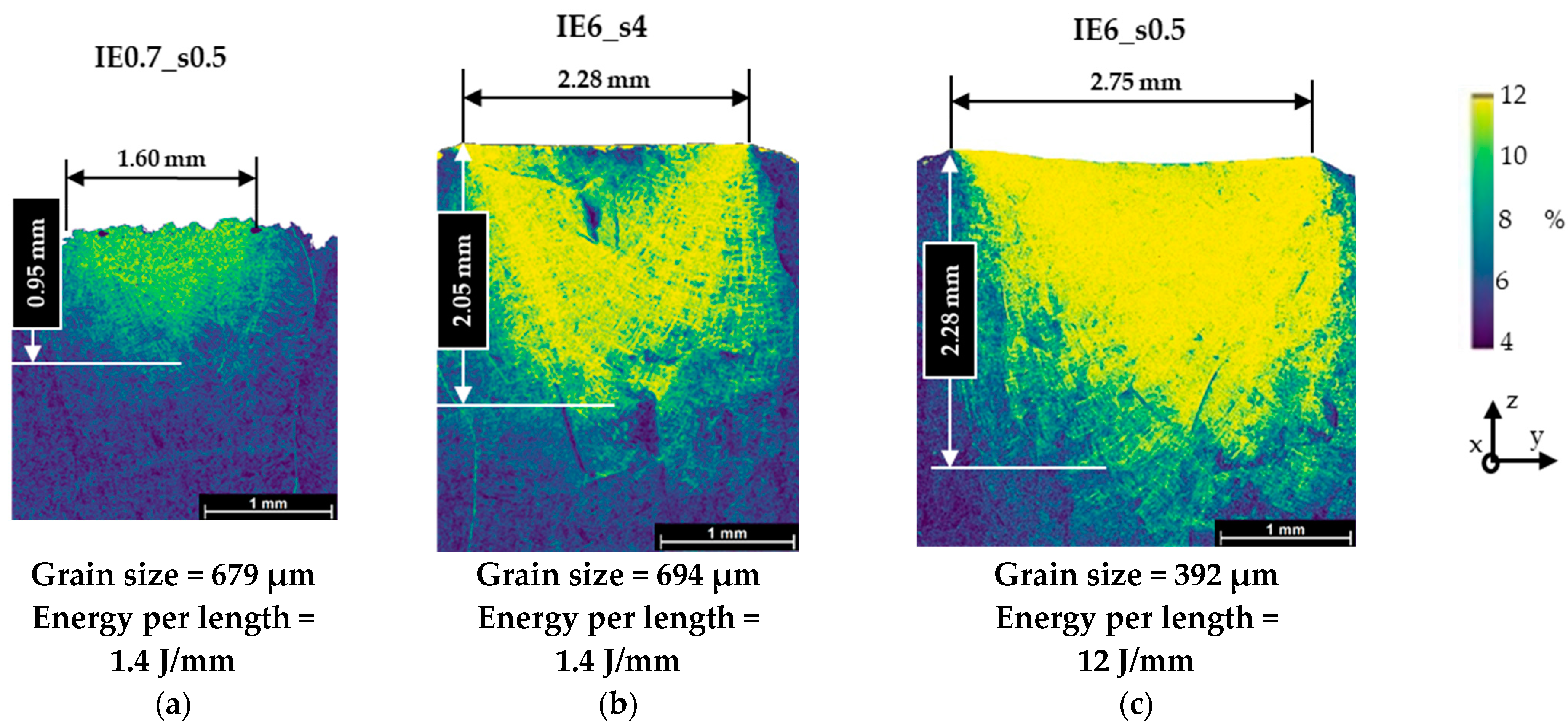
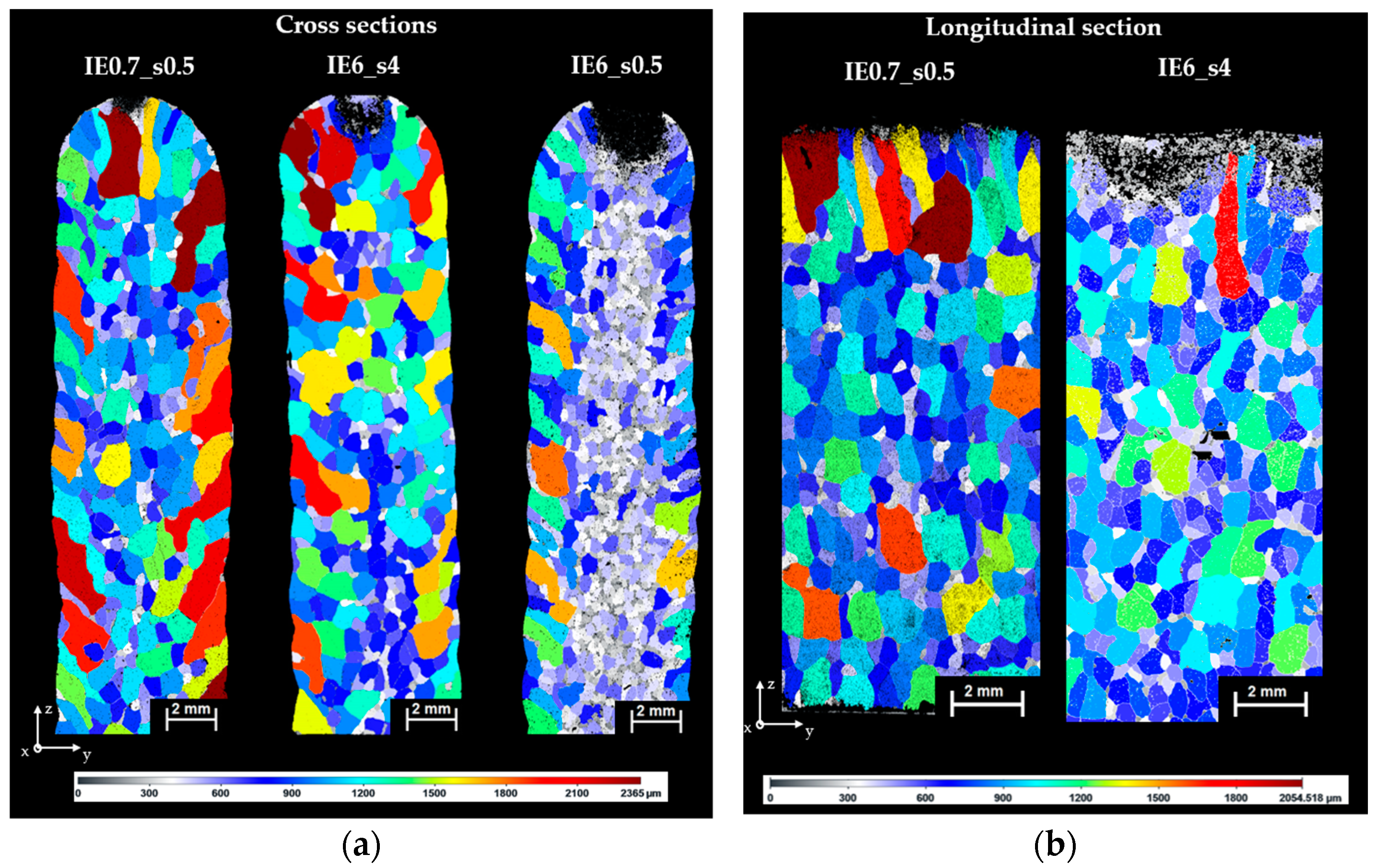
3.1.3. Varying Tool Energy

To compare the two tools with different energies of 0.7 and 6 J, the tool radius was kept constant. For the same step distance of 0.5 mm, the grain size of the 6 J energy is 40% smaller than that of the 0.7 J, while the deformation depth is considerably larger (Table 4). However, it can be observed that for very distinct parameters (IE6_4 and IE0.7_0.5), the grain size obtained is very similar, ~2% difference. Furthermore, when considering the depth of deformation for both conditions, the low energy tool shows a shallower value than the 6 J one.
To further understand the correlation between the plastic deformation and the grain size obtained, the strain maps in Figure 10 were obtained, as well as EBSD maps in the cross sectional and longitudinal plane in Figure 11. Figure 10 shows that, although IE6_s4 and IE0.7_s0.5 have different strain distributions, the grain sizes are the same. Not only does the depth of deformation double for the 6J tool, but also the intensity of the strain is considerably higher. Figure 11a shows that the distribution of the grains is similar in the cross section for these conditions. When looking at the longitudinal section, the top of the wall has columnar grains of approximately 1.2 mm maximum axis length for the 0.7 J tool, which is similar to the layer height of the newly deposited layer Figure 11b. However, for the 6 J tool, the microstructure shows small grains in the newly deposited layer.
For the same energy tool of 6 J, the strain distribution is similar for different step distances (Figure 10b,c). Even though the material is impacted eight times more, the strain depth only increases by the small amount of ~0.2 mm. However, it is shown that the increased number of impacts are causing a considerable change in the width of the wall and of the indentation. Both increase and, thus, the strain distribution is impacting a wider, but not much deeper, area for the lower step distance. The cross section a3 in Figure 11 further shows that the smaller grains become more clustered under the peening contact area where the strain obtained has higher magnitude.

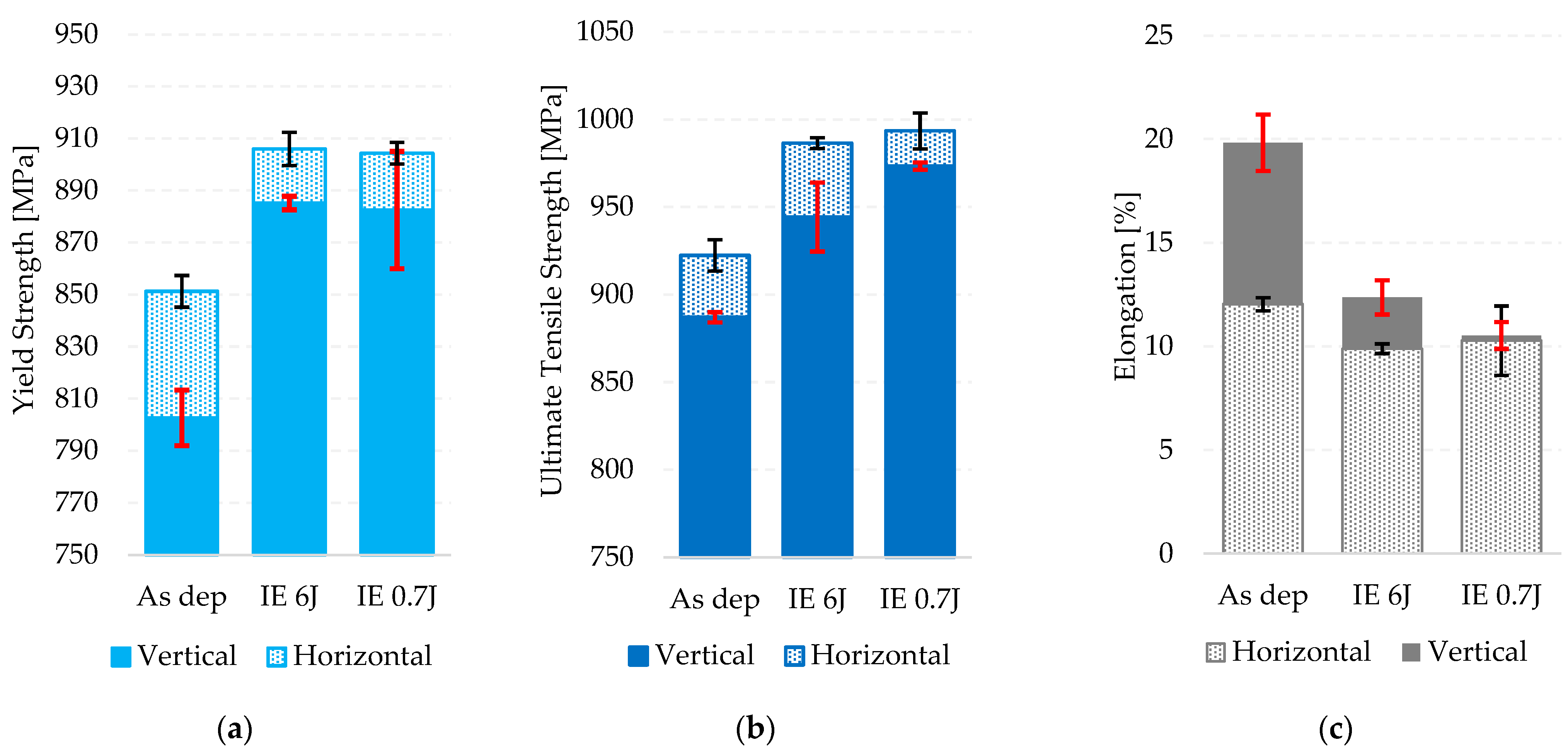
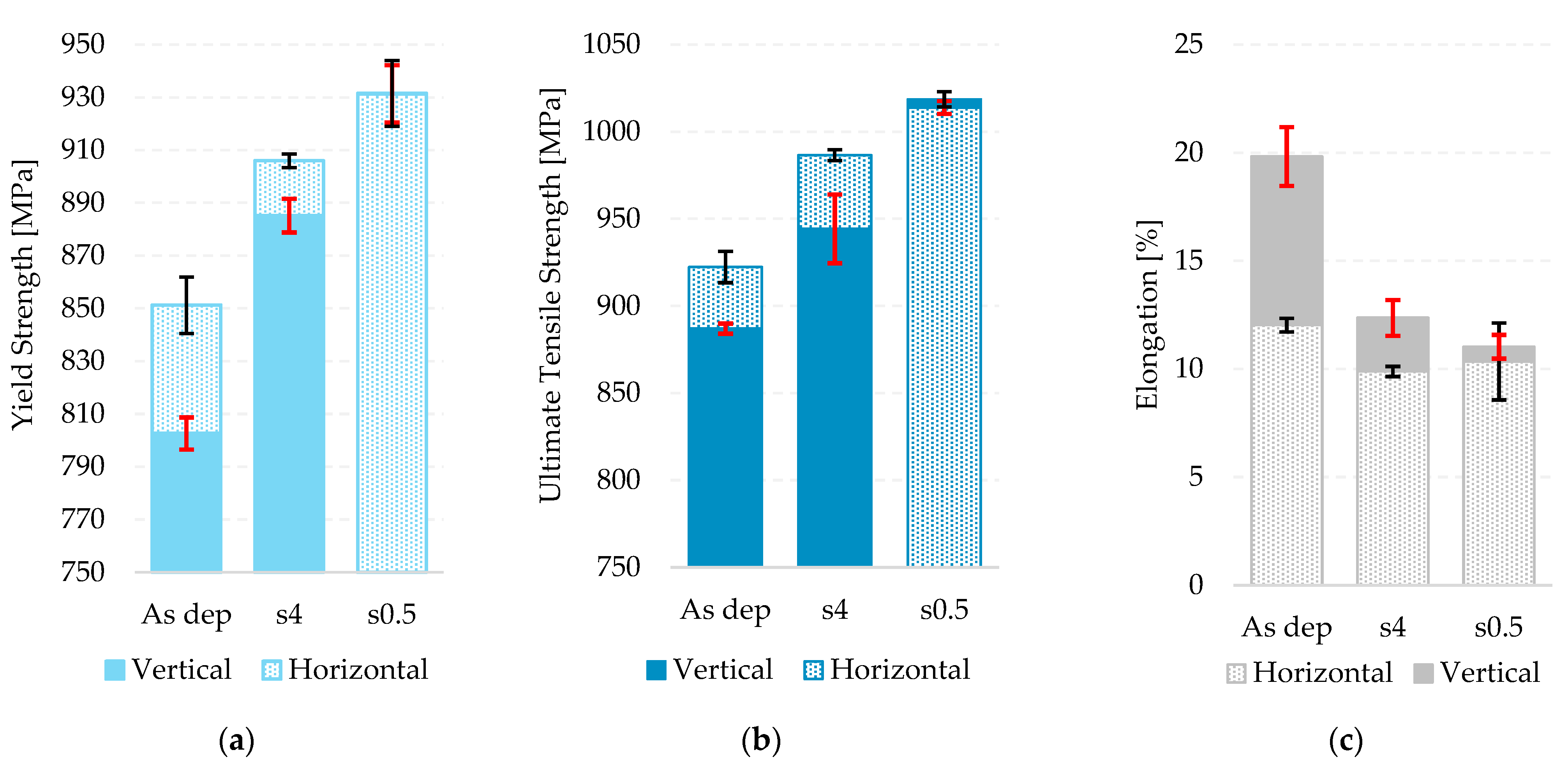
3.2. Tensile Properties

To further understand the impact of peening, the mechanical properties of the material were measured for the as deposited condition and compared to the MHP samples with the same grain size and tool radius.
MHP conditions have higher Yield Strength (YS) and Ultimate Tensile Strength (UTS), while the elongation is reduced (Figure 12 and Figure 13). Figure 12 shows that, for IE6_s4 and IE0.7_s0.6, a similar YS was obtained in both directions for both energy tools. The UTS for the 6 J tool is similar in the horizontal direction to the 0.7 J, but the value for the vertical direction is lower. However, if the standard deviation is considered, the values spread over a similar range. Regarding the elongation, the values are again similar within experimental error. Thus, the same tensile properties could be achieved by two different peening tools with very different energy levels. Moreover, the anisotropic behavior shown for the as deposited condition is eliminated when peening is applied, i.e., the vertical and horizontal directions show similar properties. In addition, the 0.7 J tool showed an even better effect than the 6 J tool.
Figure 13 shows that by decreasing the step distance, the strength improves, and the elongation decreases. The difference in the YS and UTS is approximately 20 MPa from a 4 mm to a 0.5 mm step distance. Moreover, the material has a highly isotropic behavior for smaller step distance. Considering that the robot travel speed is significantly slower for the 0.5 mm step distance (150 mm/s to 18 mm/s), a trade-off between productivity and mechanical properties can be considered.

4. Discussion

The results showed that there is a strong correlation between the MHP parameters, such as tool radius, step distance and energy, and the resulting grain size and mechanical properties. However, there are inconsistencies when trying to rationalize the EBSD-based strain measurements and the resultant beta grain size and distribution (Figure 10 and Figure 11).
Previous studies suggest that the plastic strain applied is the most important parameter driving recrystallisation in WAAM Ti-6Al-4V material [20,41]. In Figure 14, all the data from Section 3.1. (Figure 7 and Figure 9 and Table 4) are re-plotted as a function of the depth of deformation. The depth of deformation here is used as an indication of the engineering plastic strain obtained during the deformation mechanism.
It is observed that, when there is no overlap between indents (step distance of 4 and 8 mm), much larger grains are obtained for the larger step distance, despite the same depth of plastic deformation. Notably, as the material is being more often impacted, there will be more strain applied overall for the smaller step distance, but the same local plastic strain is achieved. Also, the depth of deformation achieved with 0.7 J energy tool was considerably lower, yet the same grain size as the 6 J tool can be observed. Only when subsequent impacts started overlapping (s     4 mm) for the same energy tool did the depth of deformation and grain size follow a linear trend. This suggests that there are other crucial factors not being considered, such as energy accumulation and deformation dynamics.

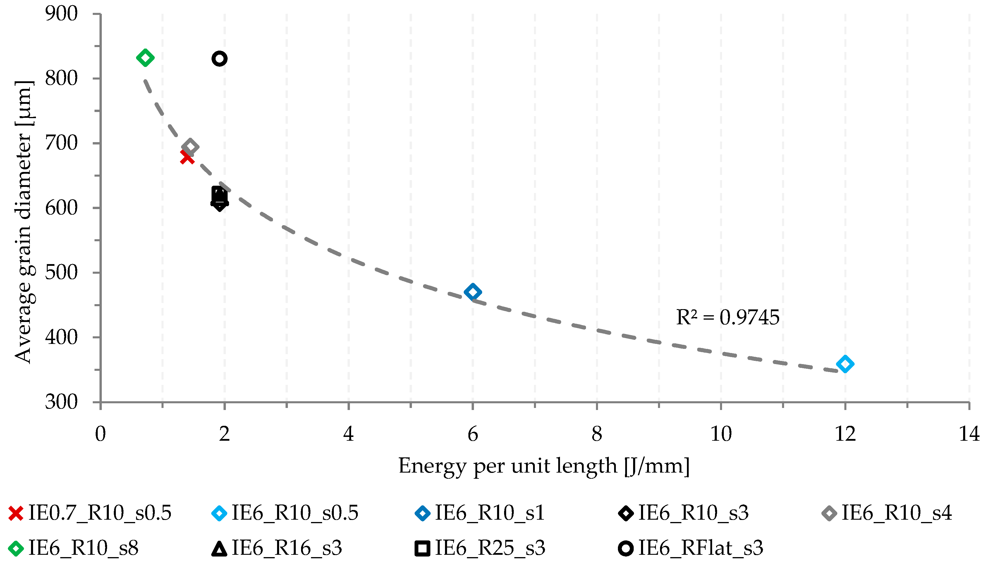
4.1. Contribution of Energy per Unit Length

In Figure 15, the average grain size for all conditions is shown as a function of energy per unit length (EPL). EPL is defined as the energy applied to the material resulting from the number of impacts and the energy supplied by the tool per unit length (Equation (1) in Section 2.2.2).
Apart from the flat tool, all the remaining cases follow the same trend, indicating the importance of EPL. The variation in grain size with EPL can be intuitively understood when comparing the same impact energy tool. In such case, the step distance is affecting the change in energy per unit length, and, as the step distance decreases, the material is more often impacted, which results in higher energy applied. Previously presented strain and EBSD maps (Section 3.1.3) of the 6 J tool with step sizes of 4 and 0.5 mm show very small variations in the strain depth and distribution (~0.3 mm). However, a decrease in average grain size of ~44% is observed. This shows discrepancies with the work conducted by Donoghue et al. [20] in which the plastic strain distribution correlates directly to the microstructural refinement achieved. If that was the case, the grain size of these two samples would be very similar, which is not shown in the present work. Thus, this highlights the importance of EPL and the role of energy accumulation in grain refinement. Further metallurgical analysis exceeds the scope of this paper and will be focus of a future publication by the authors.
EPL also allows the comparison of different energy tools. For the 0.7 and 6 J tools, the same grain size was achieved when the EPL was constant, despite a very different depth of deformation, strain depth and distribution. Both the strain depth on the strain maps and the depth of deformation for the low energy tool are approximately half of that achieved with the higher energy tool. These results agree with the simulations of MHP performed by Wied [42] in which the plastic strain depth and intensity are deeper and stronger for higher energies applied. However, it shows incoherences with the work of Donoghue et al. [20], as previously discussed.
For a low energy tool to achieve the same EPL as a high energy one, it must have a smaller step distance, i.e., it has to impact the material more often to compensate for the lack of impact energy. With a different number of impacts, the way the wall is being impacted changes considerably. Furthermore, it was noted that for the flat radius, even with the same energy tool, the grains obtained do not follow the trend (Figure 15). It was previously discussed that the contact area is much larger for the flat radius which affects the energy distribution of the impact and leads to a shallower depth of deformation. Thus, besides the EPL, the way the material is impacted is also relevant. In the following section, a different theory is suggested for the MHP impact into the material and its contribution to microstructural changes.

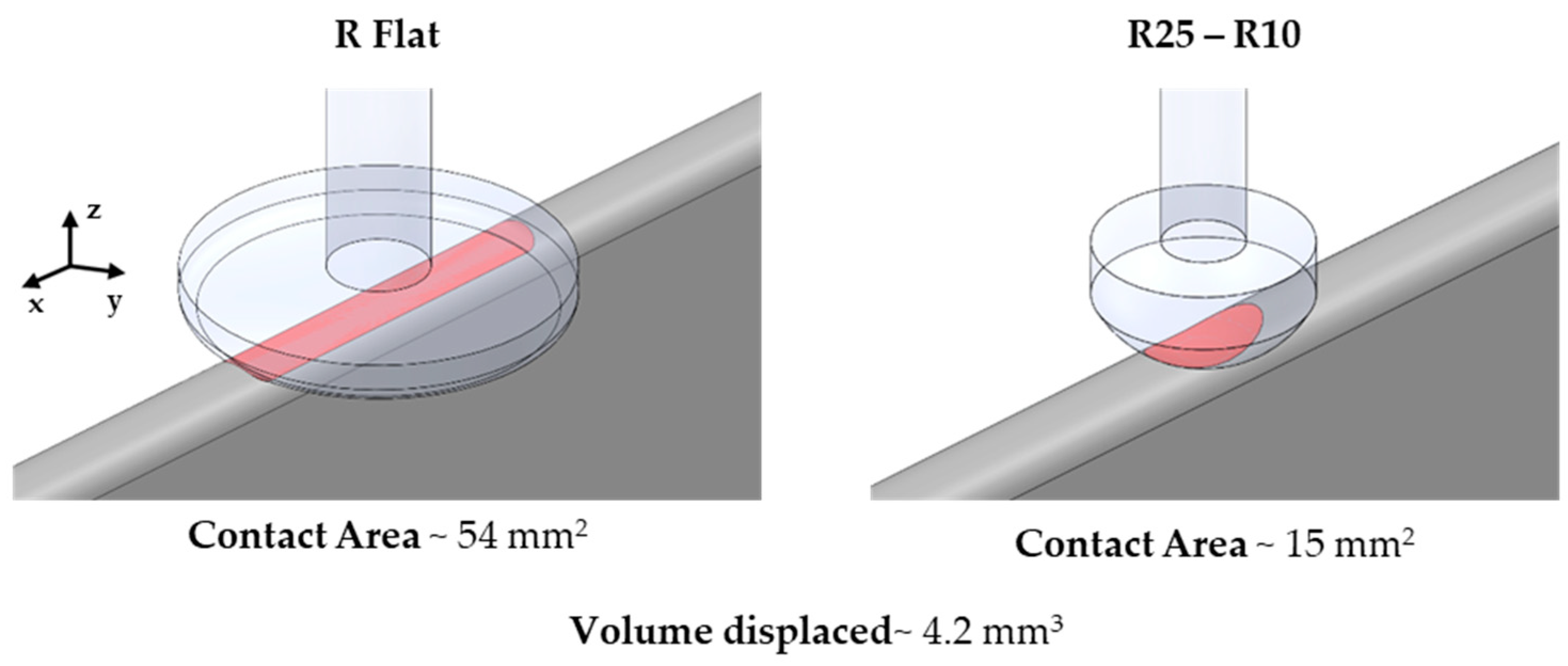
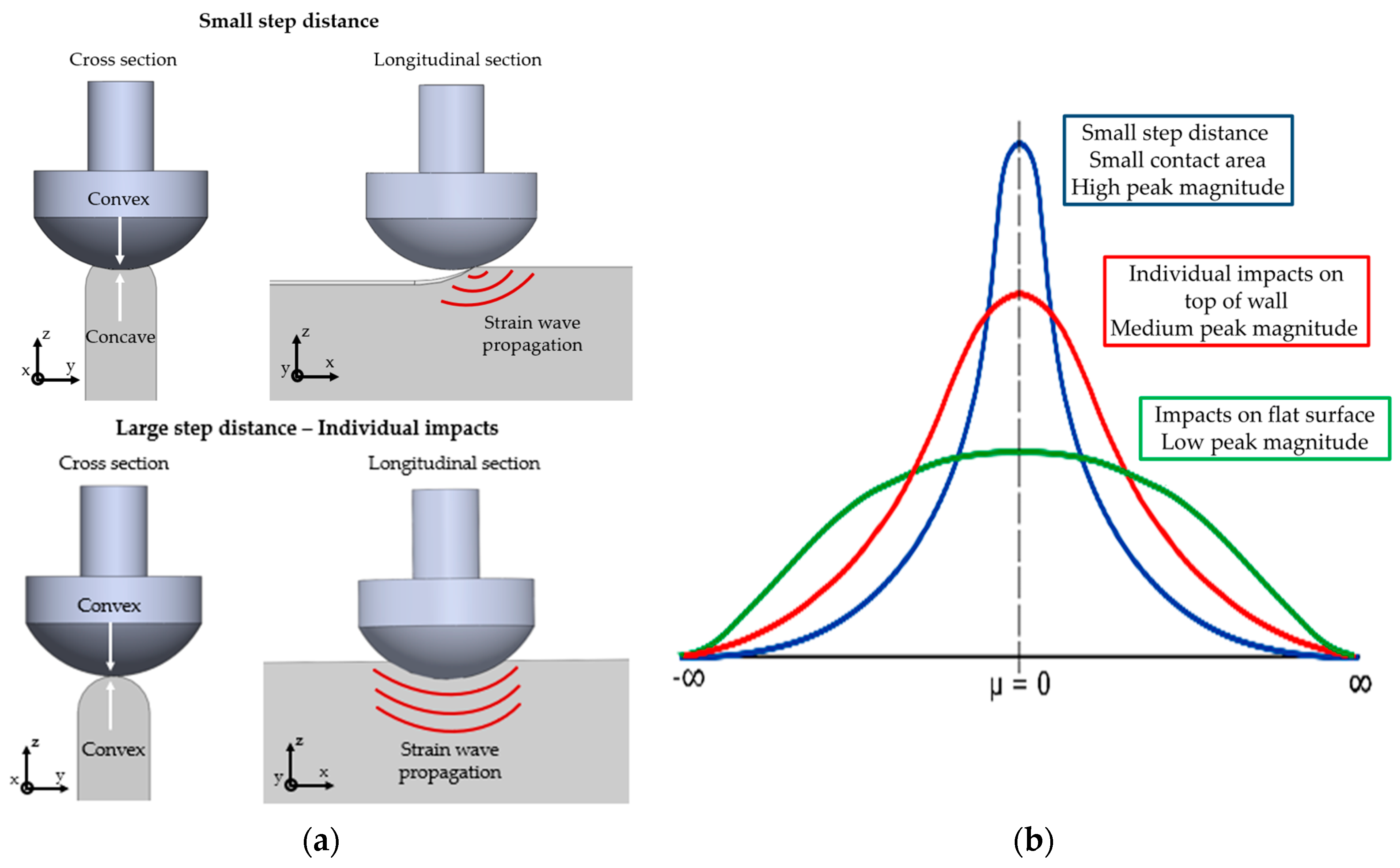
4.2. Dynamic Deformation of MHP

Neither the depth of deformation nor the EPL fully explain the results of the present paper. EPL was able to correlate very well most combination of parameters, but for the flat radius, a significant deviation from the trend line was observed. Also, the depth of deformation of similar EPL results with different energy tools was very distinct. In this case, to obtain the same EPL, the step distance of the lower energy tool is much smaller to compensate for the lack energy. The only thing changing, is the way the top of the wall is being deformed. Thus, an alternative explanation is proposed based on Vasu et al. [43] results on plasticity on different curvatures.
The interaction between the surface of the tool and the top of the wall changes according to the tool radius and step distance. The flat radius did not achieve the same grain size as the other radii, due to the much larger contact area with the top of the wall. This led to the distribution of the tool impact energy over a larger area and resulted in a shallower depth of deformation. Based on previous studies, it was expected that the smallest radius would achieve the deepest plastic deformation [42,44], but here it is shown that they all have similar values. This is attributed to the fact that, in MHP, deformation is 3-dimensional. When the material is deformed in a single bead wall, the lack of lateral restraint results in a change in width of the wall that accompanies the deformation applied vertically. Thus, when the same amount of energy is applied, the total volume displaced is similar for all conditions and independent of the radius, which agrees with Tabor [45] and Johnson [46] (Figure 8).
When the material is deformed with overlapping indents, i.e., small step distance, the top of the wall is similar to a concave surface (Figure 16a). Thus, it is expected that the strain wave distribution produced by the impact changes [43]. The peak magnitude increases and becomes more localized within the initial contact area between the tool and the wall, similar to the interaction of a convex shape with a concave one (Figure 16). If there is marginal or no overlap between the indents, the elastic–plastic strain wave between both surfaces should propagate elliptically through the material in all directions with approximately the same rate (Figure 16a and Figure 17), but some microstructural effects may affect this propagation [36]. This interaction is similar to two convex surfaces, such as the tool and the top of the wall. According to Vasu et al. [43], a concave shape obtains increased plasticity of the material when compared with convex shapes, which was attributed to the increase in the peak pressure magnitude of the wave.
In summary, a small step distance results in a small contact area which translates in a high peak of elastic-plastic strain wave. This represents a greater strain rate (inclination of the wave form-derivative of the curve) and narrower profile with higher intensity (Figure 16b). When the step distance increases but is still applied to a curved surface (top of the single bead wall), the magnitude of the wave form reduces, and when applied to a flat surface is the even lower (e.g., flat radius with top of wall). Thus, considering the changes to the top wall morphology during MHP, another contributing factor for the elastic–plastic strain wave propagation and its effect on the grain refinement of the material can be attributed to the dynamic deformation and wave propagations within the material.

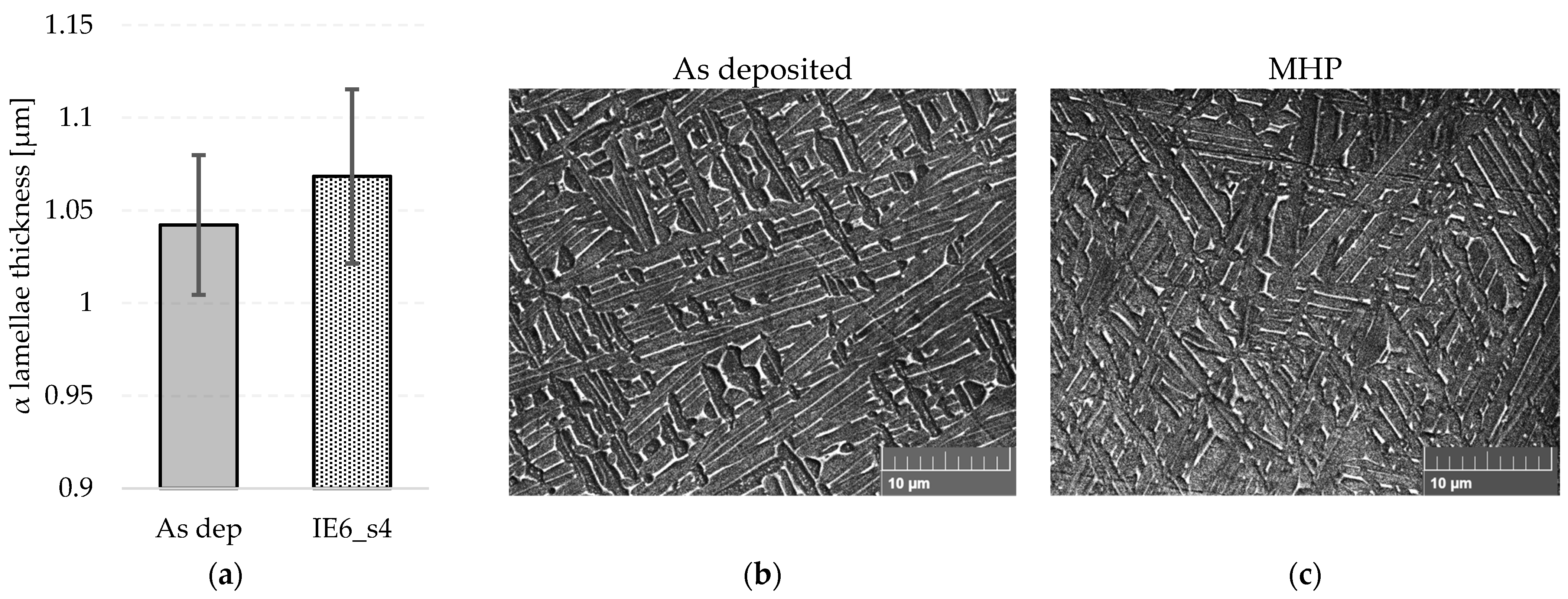
4.3. Mechanical Properties and Prior-β Grain Refinement

When inter-pass MHP was applied, both YS and UTS increased compared to the reference as deposited specimen. It is commonly known that in Ti-6Al-4V, tensile properties are mainly controlled by the α lamellae size and texture [11]. However, the measurements of α in the current work showed only a small change between the as deposited and peened conditions, and this difference is known to not produce any significant variation in material strength (Figure 18) [47,48]. These findings are in disagreement with works by Martina et al. [6], who showed that cold rolling induced a significant reduction in α lamellae size. This was also supported by Byun et al. [24], who found similar results for MHP. The methodologies of both studies were very different from the present work and variations on the equipment employed, deposition parameters, and control of inter-pass temperature are factors that affect the α lamellae size and, consequently, the mechanical properties [49]. In the present work, these variables were carefully controlled to ensure that the as deposited and peened samples could be reliably compared directly.
As the tensile properties do not seem to be influenced by the alpha lamellae size, the crystallographic and spatial orientation of the α lamellae should be taken in consideration. Although these were not studied in the present work, it is known that the orientation of the α variants is inherited from the β orientation through the BOR, during β→α transformation from the β-transus temperature [11]. Thus, EBSD texture maps are shown in Figure 19 and a significant reduction in texture of ~14 multiple of uniform density (MUD) can be seen for the β phase (Figure 19c). Furthermore, a reduction in α texture strength of ~6 MUD is also shown when comparing the as deposited and peened conditions in Figure 19b,d. This texture weakening inherently introduces more random crystallographic orientations into the transformation microstructure, including ‘harder’ low-Schmid-factor orientations, which may reduce the aggregate Schmid factor below that of columnar-grained structures that are known to be somewhat biased towards ‘softer’ orientations inherited through the strong β texture [12,20]. A lower aggregate Schmid factor in the MHP-refined samples would tend to require more stress to activate slip and would, therefore, increase the yield strength. To what degree texture weakening and randomization of the α lath major axis each contribute to the increase in tensile strength is not clear and cannot be ascertained from the current results.

5. Conclusions

In this study, two different energy MHP tools were tested and compared. Parameters such as radius and step distance were varied to understand their effect on the average grain diameter and mechanical properties of Ti-6Al-4V WAAM material. The following conclusions can be made:
  • For all MHP conditions tested, grain refinement was achieved;
  • For different energy tools, the depth of strain is different but very similar average grain size was obtained for the same energy per unit length. This demonstrates that the strain does sufficiently explain the level of grain refinement, which contradicts previous studies;
  • A newly suggested parameter, energy per unit length (EPL), is proposed and allows combining step distance and tool energy. Higher EPL leads to smaller grain diameter;
  • The level of grain refinement was found to depend on the applied energy per length irrespective of the energy of individual impacts;
  • An explanation was proposed for the dynamic deformation in the MHP process. The contact between the wall surface and the tool insert lead to different profiles of strain wave that are obtained at different strain rates;
  • An improvement of strength was achieved with inter-pass MHP, and the material became more isotropic with the increase in energy per unit length. The increase in the tensile properties could not be attributed to the α lamellae size difference, and it was proposed that texture weakening and randomization of the α lamellae spatial orientation with regards to the loading direction could be responsible.

Author Contributions

Conceptualization, L.N. and S.W.; Data curation, L.N., S.W., A.E.D. and J.R.K.; Formal analysis, L.N., S.W., A.E.D. and J.R.K.; Investigation, L.N., S.W., A.E.D. and J.R.K.; Methodology, L.N., S.W., A.E.D. and J.R.K.; Resources, L.N., S.W., A.E.D. and J.R.K.; Writing—original draft, L.N.; Writing—review and editing, L.N., S.W., A.E.D. and J.R.K. All authors have read and agreed to the published version of the manuscript.

Funding

This research was funded by the European Union’s Horizon 2020 research and innovation program in the project LASIMM (Large Additive Subtractive Integrated Modular Machine), grant number 723600. It also received funding from the Engineering and Physical Sciences Research Council (EPSRC) through the research project NEWAM (New Wire Additive Manufacturing), grant number EP/R027218/1, and from Innovate UK in the Industrial Strategy Challenge Fund (ISCF) through the OAAM (Open Architecture Additive Manufacturing), grant number 113164.

Data Availability Statement

The data presented in this study are openly available at https://doi.org/10.17862/cranfield.rd.24242437 (accessed on 8 November 2023).

Acknowledgments

The authors would like to thank several staff members of ECOROLL AG for providing the ECOpeen-C MHP tool and for the operational support, and to Flemming Nielsen, Nisar Shah, and Steve Pope for the technical support throughout the experiments carried at the WAMC and metallurgy laboratory of Cranfield University. Furthermore, the intellectual support by Filomeno Martina, Jan Hönnige, and Jialuo Ding was greatly appreciated.

Conflicts of Interest

The authors declare no conflict of interest.

References

  1. Guo, N.; Leu, M.C. Additive Manufacturing: Technology, Applications and Research Needs. Front. Mech. Eng. 2013, 8, 215–243. [Google Scholar] [CrossRef]
  2. Rodrigues, T.A.; Duarte, V.; Miranda, R.M.; Santos, T.G.; Oliveira, J.P. Current Status and Perspectives on Wire and Arc Additive Manufacturing (WAAM). Materials 2019, 12, 1121. [Google Scholar] [CrossRef] [PubMed]
  3. Repnin, A.; Borisov, E.; Emelianov, A.; Popovich, A. Fracture Toughness of Ti6Al4V/Cp-Ti Multi-Material Produced via Selective Laser Melting. Metals 2023, 13, 1738. [Google Scholar] [CrossRef]
  4. Lin, Z.; Song, K.; Yu, X. A Review on Wire and Arc Additive Manufacturing of Titanium Alloy. J. Manuf. Process. 2021, 70, 24–45. [Google Scholar] [CrossRef]
  5. Dutta, B.; Froes, F.H. The Additive Manufacturing (AM) of Titanium Alloys. Met. Powder Rep. 2017, 72, 96–106. [Google Scholar] [CrossRef]
  6. Martina, F.; Colegrove, P.A.; Williams, S.W.; Meyer, J. Microstructure of Interpass Rolled Wire + Arc Additive Manufacturing Ti-6Al-4V Components. Metall. Mater. Trans. A Phys. Metall. Mater. Sci. 2015, 46, 6103–6118. [Google Scholar] [CrossRef]
  7. Liu, S.; Shin, Y.C. Additive Manufacturing of Ti6Al4V Alloy: A Review. Mater. Des. 2019, 164, 107552. [Google Scholar] [CrossRef]
  8. Martina, F.; Mehnen, J.; Williams, S.W.; Colegrove, P.; Wang, F. Investigation of the Benefits of Plasma Deposition for the Additive Layer Manufacture of Ti-6Al-4V. J. Mater. Process. Technol. 2012, 212, 1377–1386. [Google Scholar] [CrossRef]
  9. Lutjering, G. Titanium. In Encyclopedia of Toxicology, 3rd ed.; Elsevier: Amsterdam, The Netherlands, 2014; pp. 584–585. [Google Scholar] [CrossRef]
  10. Wang, F.; Williams, S.; Colegrove, P.; Antonysamy, A.A. Microstructure and Mechanical Properties of Wire and Arc Additive Manufactured Ti-6Al-4V. Metall. Mater. Trans. A Phys. Metall. Mater. Sci. 2013, 44, 968–977. [Google Scholar] [CrossRef]
  11. Lütjering, G. Influence of Processing on Microstructure and Mechanical Properties of (α + β) Titanium Alloys. Mater. Sci. Eng. A 1998, 243, 32–45. [Google Scholar] [CrossRef]
  12. Lunt, D.; Ho, A.; Davis, A.; Harte, A.; Martina, F.; Prangnell, P. The Effect of Loading Direction on Strain Localisation in Wire Arc Additively Manufactured Ti–6Al–4V. Mater. Sci. Eng. A 2020, 788, 139608. [Google Scholar] [CrossRef]
  13. Sequeira Almeida, P.M.; Williams, S. Innovative Process Model of Ti-6Al-4V Additive Layer Manufacturing Using Cold Metal Transfer (CMT). In Proceedings of the 21st Annual International Solid Freeform Fabrication Symposium—An Additive Manufacturing Conference, SFF 2010, Austin, TX, USA, 9–11 August 2010; pp. 25–36. [Google Scholar]
  14. Wang, F.; Williams, S.; Rush, M. Morphology Investigation on Direct Current Pulsed Gas Tungsten Arc Welded Additive Layer Manufactured Ti6Al4V Alloy. Int. J. Adv. Manuf. Technol. 2011, 57, 597–603. [Google Scholar] [CrossRef]
  15. Bermingham, M.J.; Stjohn, D.H.; Krynen, J.; Tedman-jones, S.; Dargusch, M.S. Promoting the Columnar to Equiaxed Transition and Grain Refinement of Titanium Alloys during Additive Manufacturing. Acta Mater. 2019, 168, 261–274. [Google Scholar] [CrossRef]
  16. Mereddy, S.; Bermingham, M.J.; Kent, D.; Dehghan-Manshadi, A.; StJohn, D.H.; Dargusch, M.S. Trace Carbon Addition to Refine Microstructure and Enhance Properties of Additive-Manufactured Ti-6Al-4V. JOM 2018, 70, 1670–1676. [Google Scholar] [CrossRef]
  17. Bermingham, M.J.; Kent, D.; Zhan, H.; Stjohn, D.H.; Dargusch, M.S. Controlling the Microstructure and Properties of Wire Arc Additive Manufactured Ti-6Al-4V with Trace Boron Additions. Acta Mater. 2015, 91, 289–303. [Google Scholar] [CrossRef]
  18. Kennedy, J.R.; Davis, A.E.; Caballero, A.E.; Williams, S.; Pickering, E.J.; Prangnell, P.B. The Potential for Grain Refinement of Wire-Arc Additive Manufactured (WAAM) Ti-6Al-4V by ZrN and TiN Inoculation. Addit. Manuf. 2021, 40, 101928. [Google Scholar] [CrossRef]
  19. Colegrove, P.A.; Donoghue, J.; Martina, F.; Gu, J.; Prangnell, P.; Hönnige, J. Application of Bulk Deformation Methods for Microstructural and Material Property Improvement and Residual Stress and Distortion Control in Additively Manufactured Components. Scr. Mater. 2016, 135, 111–118. [Google Scholar] [CrossRef]
  20. Donoghue, J.; Antonysamy, A.A.; Martina, F.; Colegrove, P.A.; Williams, S.W.; Prangnell, P.B. The Effectiveness of Combining Rolling Deformation with Wire-Arc Additive Manufacture on β-Grain Refinement and Texture Modification in Ti-6Al-4V. Mater. Charact. 2016, 114, 103–114. [Google Scholar] [CrossRef]
  21. Donoghue, J.; Davis, A.E.; Daniel, C.S.; Garner, A.; Martina, F.; Quinta da Fonseca, J.; Prangnell, P.B. On the Observation of Annealing Twins during Simulating β-Grain Refinement in Ti–6Al–4V High Deposition Rate AM with in-Process Deformation. Acta Mater. 2020, 186, 229–241. [Google Scholar] [CrossRef]
  22. Bleicher, F.; Lechner, C.; Habersohn, C.; Kozeschnik, E.; Adjassoho, B.; Kaminski, H. Mechanism of Surface Modification Using Machine Hammer Peening Technology. CIRP Ann. Manuf. Technol. 2012, 61, 375–378. [Google Scholar] [CrossRef]
  23. Hacini, L.; Van Lê, N.; Bocher, P. Evaluation of Residual Stresses Induced by Robotized Hammer Peening by the Contour Method. Exp. Mech. 2009, 49, 775–783. [Google Scholar] [CrossRef]
  24. Byun, J.-G.; Yi, H.; Cho, S.-M. The Effect of Interpass Peening on Mechanical Properties in Additive Manufacturing of Ti-6Al-4V. J. Weld. Join. 2017, 35, 6–12. [Google Scholar] [CrossRef]
  25. Lee, W.-S.; Lin, C.-F. Plastic Deformation and Fracture Behaviour of Ti–6Al–4V Alloy Loaded with High Strain Rate under Various Temperatures. Mater. Sci. Eng. A 1998, 241, 48–59. [Google Scholar] [CrossRef]
  26. Neto, L.; Williams, S.; Ding, J.; Hönnige, J.; Martina, F. Mechanical Properties Enhancement of Additive Manufactured Ti-6Al-4V by Machine Hammer Peening. In Proceedings of the International Conference on Advanced Surface Enhancement, Singapore, 10–12 September 2019; pp. 121–132. [Google Scholar]
  27. Hönnige, J.R.; Colegrove, P.; Williams, S. Improvement of Microstructure and Mechanical Properties in Wire + Arc Additively Manufactured Ti-6Al-4V with Machine Hammer Peening. Procedia Eng. 2017, 216, 8–17. [Google Scholar] [CrossRef]
  28. Hönnige, J.R.; Davis, A.E.; Ho, A.; Kennedy, J.R.; Neto, L.; Prangnell, P. The Effectiveness of Grain Refinement by Machine Hammer Peening in High Deposition Rate Wire-Arc AM Ti-6Al-4V. Metall. Mater. Trans. A 2020, 51A, 3692–3703. [Google Scholar] [CrossRef]
  29. Schulze, V.; Bleicher, F.; Groche, P.; Guo, Y.B.; Pyun, Y.S. Surface Modification by Machine Hammer Peening and Burnishing. CIRP Ann. Manuf. Technol. 2016, 65, 809–832. [Google Scholar] [CrossRef]
  30. Oechsner, M.; Wied, J.; Stock, J. Influence of Machine Hammer Peening on the Tribology of Sheet Forming. Adv. Mater. Res. 2014, 966–967, 397–405. [Google Scholar] [CrossRef]
  31. Ding, J.; Colegrove, P.; Martina, F.; Williams, S.; Wiktorowicz, R.; Palt, M.R. Development of a Laminar Flow Local Shielding Device for Wire+arc Additive Manufacture. J. Mater. Process. Technol. 2015, 226, 99–105. [Google Scholar] [CrossRef]
  32. Zhao, H.; Ho, A.; Davis, A.; Antonysamy, A.; Prangnell, P. Automated Image Mapping and Quanti Fi Cation of Microstructure Heterogeneity in Additive Manufactured Ti6Al4V. Mater. Charact. 2019, 147, 131–145. [Google Scholar] [CrossRef]
  33. Davies, P.S. An Investigation of Microstructure and Texture Evolution in the Near-Alfa Titanium Alloy Timetal 834; The University of Sheffield: Sheffield, UK, 2009. [Google Scholar]
  34. Davies, P.S.; Wynne, B.P.; Rainforth, W.M.; Thomas, M.J.; Threadgill, P.L. Development of Microstructure and Crystallographic Texture during Stationary Shoulder Friction Stir Welding of Ti-6Al-4V. Metall. Mater. Trans. A Phys. Metall. Mater. Sci. 2011, 42, 2278–2289. [Google Scholar] [CrossRef]
  35. Gey, N.; Humbert, M. Specific Analysis of EBSD Data to Study the Texture Inheritance Due to the β → α Phase Transformation. J. Mater. Sci. 2003, 8, 1289–1294. [Google Scholar] [CrossRef]
  36. Humbert, M.; Gey, N. The Calculation of a Parent Grain Orientation from Inherited Variants for Approximate (b.c.c. ± h.c.p.) Orientation Relations. J. Appl. Crystallogr. 2002, 35, 401–405. [Google Scholar] [CrossRef]
  37. Beausir, B.; Fundenberger, J.J. Analysis Tools for Electron and X-ray Diffraction, ATEX–Software, Software version 3.17; University of Lorraine: Lorraine, France, 2017.
  38. Buchheit, T.E.; Wellman, G.W.; Battaile, C.C. Investigating the Limits of Polycrystal Plasticity Modeling. Int. J. Plast. 2005, 21, 221–249. [Google Scholar] [CrossRef]
  39. Davis, A.E.; Martina, F.; Prangnell, P.B.; Hönnige, J.R. Quantification of Strain Fields and Grain Refinement in Ti-6Al-4V Inter-Pass Rolled Wire-Arc AM by EBSD Misorientation Analysis. Mater. Charact. 2020, 170, 110673. [Google Scholar] [CrossRef]
  40. BS EN 2002-1:2005; Metallic Materials—Test Methods—Part1: Tensile Testing at Ambient Temperature. European Committee for Standardization: Brussels, Belgium, 2005.
  41. Davis, A.E.; Caballero, A.; Prangnell, P.B. Confirmation of Rapid-Heating Beta Recrystallization in Wire-Arc Additively Manufactured Ti-6Al-4V. Materialia 2020, 13, 100857. [Google Scholar] [CrossRef]
  42. Wied, J. Oberflächenbehandlung von Umformwerkzeugen durch Festklopfen; TU: Darmstadt, Germany, 2011. [Google Scholar]
  43. Vasu, A.; Hu, Y.; Grandhi, R.V. Differences in Plasticity Due to Curvature in Laser Peened Components. Surf. Coat. Technol. 2013, 235, 648–656. [Google Scholar] [CrossRef]
  44. Hertz, H. Ueber Die Berührung Fester Elastischer Körper. J. Für Die Reine Und Angew. Math. 1882, 92, 156–171. [Google Scholar]
  45. Tabor, D. The Hardness of Metals; Oxford University Press: Oxford, UK, 1951. [Google Scholar]
  46. Johnson, K.L. Contact Mechanics; Cambridge University Press: Cambridge, UK, 1987. [Google Scholar]
  47. Keist, J.S.; Palmer, T.A. Development of Strength-Hardness Relationships in Additively Manufactured Titanium Alloys. Mater. Sci. Eng. A 2017, 693, 214–224. [Google Scholar] [CrossRef]
  48. Zuback, J.S.; DebRoy, T. The Hardness of Additively Manufactured Alloys. Materials 2018, 11, 2070. [Google Scholar] [CrossRef]
  49. Nguyen, H.D.; Pramanik, A.; Basak, A.K.; Dong, Y.; Prakash, C.; Debnath, S.; Shankar, S.; Jawahir, I.S.; Dixit, S.; Buddhi, D. A Critical Review on Additive Manufacturing of Ti-6Al-4V Alloy: Microstructure and Mechanical Properties. J. Mater. Res. Technol. 2022, 18, 4641–4661. [Google Scholar] [CrossRef]
Figure 1. Image of (a) the deposition and MHP step up and of (b) the top of the wall with the as deposited and one of the peened conditions showing.
Metals 13 01888 g001
Figure 2. Image of (a) the 6J Atlas Copco MHP tool impacting the top of a wall. Schematic representation of (b) peening deformation on top of a single-pass wall created by the 6J Atlas Copco tool with the overlapped indents highlighted in blue. Top view of the overlapped indents (c) in a line with a defined step distance (s).
Metals 13 01888 g002
Figure 3. Top view of the walls deformed with inter-pas MHP with radiuses (a) R 6 and (b) R 4. The center line of the bead is highlighted in red for reference.
Metals 13 01888 g003
Figure 4. Cross-section view of (a) the measured depth of deformation with the 3D microscope (3DM) and the depth of deformation obtained through optical microscope (OM) for a single-pass wall. Representation of (b) the location of the strain field analyzed for Local Average Misorientation (LAM) EBSD strain mapping.
Metals 13 01888 g004
Figure 5. Tensile coupons (a) position and (b) dimensions (all units in mm).
Metals 13 01888 g005
Figure 6. Optical macroscopy images of (a) the cross-section of as deposited and inter-pass MHP with R Flat, and the variation in grain size of the red area highlighted when changing, (b) the tool radius, (c) the step distance, and (d) the impact energy of the tool.
Metals 13 01888 g006
Figure 7. Plot of the (a) average grain diameter according to tool radius and (b) the contact area and depth of deformation (height reduction) for each respective radius.
Metals 13 01888 g007
Figure 8. Schematic representation of the indent contact area for R Flat and smaller radiuses with the same volume displaced.
Metals 13 01888 g008
Figure 9. Plot of the (a) average grain diameter vs. the step distance and (b) depth of deformation measured through optical microscopy and wall width difference for each step distance.
Metals 13 01888 g009
Figure 10. Strain map using the EBSD-LAM technique for (a) 0.7 J and 0.5 mm step distance, (b) 6 J and 4 mm step distance, and (c) 6 J and 0.5 mm step distance.
Metals 13 01888 g010
Figure 11. Grain size distribution maps for (a) cross-sections and (b) longitudinal sections the of different MHP conditions taken in the middle of the walls, as described in Section 2.3.1.
Metals 13 01888 g011
Figure 12. Comparison of the tensile properties for the as deposited and inter-pass peened walls with the same grain size and radius of 10 mm, but different tool energies of 0.7 J and 6 J for (a) Yield Strength, (b) Ultimate Tensile Strength and (c) Elongation. Corresponding standard deviation is indicated for each value, where the red coloring refers to the vertical error bars, while the black to the horizontal ones.
Metals 13 01888 g012
Figure 13. Comparison of the tensile properties for the as deposited and inter-pass peened walls with the step distance of 4 mm (s4) and 0.5 mm (s0.5) with the same tool energy of 6 J and radius of 10 mm for (a) Yield Strength, (b) Ultimate Tensile Strength and (c) Elongation. Corresponding standard deviation is indicated for each value, where the red coloring refers to the vertical error bars, while the black to the horizontal ones.
Metals 13 01888 g013
Figure 14. Average grain diameter as a function of the depth of deformation (replotted data from Section 3.1).
Metals 13 01888 g014
Figure 15. Average grain diameter as a function of the energy per unit length applied to all the conditions tested. The trend line does not include the values for R Flat.
Metals 13 01888 g015
Figure 16. Schematic representation of the wall being deformed for (a) small step distance and large step distance (individual impacts), in the longitudinal direction. The peak magnitude distribution (b) is represented for the different deformation interactions in MHP.
Metals 13 01888 g016
Figure 17. Overlaid β-reconstructed EBSD maps accepting increasing deviation from the ideal BOR ( 1 6 ° ) to infer the plastic strain distribution of two impacts for peening step size of 8 mm and radius of 10 mm.
Metals 13 01888 g017
Figure 18. Plot of the (a) α lamellae thickness for the as deposited and MHP conditions with 6 J and 4 mm step distance. SEM imaging of the (b) as deposited and (c) MHP conditions.
Metals 13 01888 g018
Figure 19. EBSD maps of (a) reconstructed β orientation and (b) α orientation for the as deposited and MHP sample with impact energy of 6 J and step distance of 4 mm. Inverse pole figures are shown for the same conditions for the (c) β and (d) α.
Metals 13 01888 g019
Table 1. Chemical composition of wire used for all walls [wt%].
TiAlVFeOCNOthers
Balance6.14–6.153.91–3.940.17–0.180.150.0210.007–0.0080.0172
Table 2. Deposition parameters.
Current [A]Wire Feed Speed [m/min]Travel Speed [mm/s]Wire
Diameter [mm]
Work Piece Distance [mm]Plasma Gas Flow [L/min]Shielding Gas Flow [L/min]
1452.451.280.88
Table 3. Parameters used for inter-pass MHP of single pass deposition.
Impact Energy–IE [J]Tool Radius–R [mm]Step Distance–s [mm]Peening Velocity–v [mm/s]Sample Name
0.7
(F = 225 Hz)
100.5112.5IE0.7_R10_s0.5 *
6 J
(F = 36 Hz)
108.33300IE6_R10_s8
4.16150IE6_R10_s4 *
3.13112.5IE6_R10_s3
136IE6_R10_s1
0.518IE6_R10_s0.5 *
Flat 3.13112.5IE6_Flat_s3
25IE6_R25_s3
16IE6_R16_s3
6IE6_R6_s3
4IE6_R4_s3
* Conditions tested to obtain tensile properties.
Table 4. Summary of the average grain diameter and OM depth of deformation for three different conditions, to compare the effect of tool energy with a constant radius of 10 mm.
Average Grain Diameter [µm]OM Depth of Deformation [µm]
IE0.7_s0.567970.2
IE6_s4694158.5
IE6_s0.5392530.0
Disclaimer/Publisher’s Note: The statements, opinions and data contained in all publications are solely those of the individual author(s) and contributor(s) and not of MDPI and/or the editor(s). MDPI and/or the editor(s) disclaim responsibility for any injury to people or property resulting from any ideas, methods, instructions or products referred to in the content.

