Article

Understanding Mold Wear Mechanisms and Optimizing Performance through Nico Coating: An In-Depth Analysis

Department of Metal Materials, College of Materials Science and Engineering, Dongguan University of Technology, Dongguan 523000, China
*
Author to whom correspondence should be addressed.
Metals 2023, 13(12), 1933; https://doi.org/10.3390/met13121933
Submission received: 19 October 2023 / Revised: 18 November 2023 / Accepted: 21 November 2023 / Published: 24 November 2023

Abstract

:
This research investigates the wear mechanism of molds and examines the worn areas using high power microscopes and SEM (Scanning Electron Microscopy). In addition, EDS (Energy Dispersive Spectroscopy) and XRF (X-ray fluorescence) techniques are used to compare the worn areas with the normal areas. The results indicate that the wear mechanism of the molds is similar to adhesive wear. To address the issue of die wear, the application of Nico coating to the copper substrate surface is investigated. Two sample preparation methods, namely DC power supply and dual pulse power supply, are employed. SEM analysis shows that the sample group prepared using the dual pulse power supply has a relatively dense surface coating. The samples with a 60:40 weight ratio of Nico exhibit the highest average hardness and thickness, with minimal dispersion as indicated by the low standard deviation. The samples also show minimal roughness. Repeat tests under the same conditions confirm that the coating surface remains dense and uniform with a hardness of 467.628 hv, a thickness of 43.0665 μm and a roughness of 4.331 nm. The nanoindenter test results show that the coating has improved wear resistance (−28.7 nm) compared to the original mold (−142.4 nm), an increase of 80%.
Keywords:
mold; wear; coating

1. Introduction

Die casting molds are essential for the production of die castings, and their longevity greatly influences cost. To meet heightened performance demands, as well as reduce the expense of low-pressure casting and enhance overall societal benefits, the mechanical properties and durability of die-casting molds need to fulfil increasing standards. Numerous factors impact the lifespan of metal die casting molds, with wear being a crucial element. Friction results in the wear, consumption or deformation of material in relative motion. This not only causes material consumption, but also affects mold lifespan.
The interdisciplinary nature of this process presents challenges to fully understanding its laws. Numerous scientists have conducted extensive research on wear. EI Nagar and EI Sayed [1] summarized different sliding wear mechanisms, which included adhesive wear, abrasive wear, fatigue wear, corrosion wear, and thermal wear. Additionally, the article discusses various factors that impact sliding wear, such as surface roughness, material properties, environmental conditions, load and speed.
N. Nemat-AllaWang, Zhang, and Li [2] investigated the wear mechanism in sliding contact by numerical simulation. It was found that contact pressure, sliding velocity and material properties have important effects on wear.examined the tribological performance of sliding bearings and modelled the wear process of sliding bearings using finite element analysis (FEA). The significance of Finite Element Analysis (FEA) as a predictive tool in comprehending the wear mech-anism of sliding bearings is emphasized in this article.
The studies of A. Khoshnevisan and M. Rezaei [3] focused on the wear mechanisms of low carbon martensitic steels un-der sliding conditions. They found that the microstructure and hardness of the material surface have an important in-fluence on the wear resistance under sliding friction conditions. In addition, they found that the wear resistance of low carbon martensitic steels is affected by factors such as the coefficient of friction, the effect of lubricant, and thermal load. The studies of P. Gupta and A. Gupta [4] were mainly focused on the wear mechanism of friction partner in reciprocat-ing motion. They found that the wear of the friction pair is influenced by factors such as material properties, lubrication conditions and surface roughness. In addition, they found that different lubrication conditions can significantly affect the wear resistance of the friction pair. S. Zhang, H. Wang and C. Wang [5] focused on the relationship between surface integrity and wear mechanism of bearing steel in rolling contact fatigue failure. They found that surface integrity has an important effect on fatigue life and wear. In addition, they found that surface integrity can influence the rolling contact fatigue failure process by affecting the mechanical properties and wear resistance of the material.
As shown in Figure 1, the general wear process can be roughly divided into three stages [6]. Normal operation of molds tends to occur during the steady wear stage [7,8], which is considered from the perspective of changes in the wear process. Therefore, to prolong the mold life, it is crucial to extend the steady wear phase for as long as possible. A large number of studies [9,10] have shown that wear is the main factor in 75% of mold failures and is the main cause of mold failure. Therefore, wear should be avoided as it is often considered dangerous. Understanding and managing wear and extending mold life requires an understanding of the laws of wear. Wear is a complex process controlled by many variables. It is not possible to include all the microscopic wear mechanisms in a single equation, as there are many mechanisms that can lead to deterioration of the surface layer. To better understand wear mechanisms, wear is often classified. Three factors are considered when classifying general wear:
(1)
Surface interactions, which include mechanical movement (sliding or rolling) and the type of molecular interactions occurring at the surface.
(2)
Changes in the surface layer: differences in composition, e.g., the amount of carbon in the steel, changes in physical properties, e.g., hardness, changes in chemical properties, e.g., changes in the action of the chemical coatings, and changes in the structure of the surface layer (deformation or non-deformation).
(3)
Types of damage: The main manifestations are abrasive and surface wear. Although different interpretations of wear phenomena describe specific features of wear from different perspectives, it is still difficult to provide a thorough explanation of the variations in wear phenomena. With the emergence of tools for surface microanalysis and electronic machining techniques, the study of wear has moved from macroscopic through submicroscopic to microscopic, from static to dynamic, and from qualitative to quantitative. Wear rate refers to the degree and extent of wear, which is measured by the amount of material removed from a surface per unit of sliding distance, work done, rotation or oscillation. Mass, volume or thickness measurements can be used to determine the degree of wear that has occurred.
Mold wear is inevitable during production and processing. Research has focused on finding ways to delay the severe wear, extend the period of steady wear, and minimize the break-in period. In addition to traditional theoretical studies on wear mechanisms, many modern scholars have conducted extensive research on die wear, especially in dies with copper alloy base materials. S.S. Pai, S.P. Naik. [11] investigated the wear mechanism of copper alloy moulds. It was found that the wear of moulds is influenced by material hardness, strength and fatigue re-sistance. In addition, the friction conditions and the surface treatment of the mould also have an important influence on the wear resistance of the mould. W. Zhang, Y. Li. [12] investigated the wear mechanism of copper alloy moulds at different temperatures. It was found that temperature has a significant effect on the wear resistance of the moulds. As the temperature increases, the wear of the die increases. In addition, the material composition and microstructure also affect the wear resistance of the mould. X. Wang, J. Zhang. [13] analyzed the wear mechanism of copper alloy moulds by numerical simulation. It was found that the wear of moulds is influenced by factors such as friction conditions, material properties and thermal effects. In addition, the structural design and surface treatment of the moulds also have an important influence on the wear resistance. J. Yang, Q. Liu. [14] investigated the wear mechanism of copper alloy moulds under high ve-locity impact conditions. It was found that the impact velocity has a significant effect on the wear of the mould. As the impact velocity increases, the wear of the mould increases. In addition, material hardness and toughness also have an important effect on the wear re-sistance of the mould.
Copper alloys have excellent physical and mechanical properties such as high electrical conductivity, good thermal conductivity, high strength and good corrosion resistance. Therefore, copper alloys are widely used in various industrial applications, including electronics, construction, machinery and transportation. However, during the production and processing of copper alloys, mold wear is a frequent occurrence that adversely affects productivity and product quality.
Therefore, it is of great significance to study the causes and solutions of copper alloy mold wear. A.R. Pinto. [15] investigated the wear mechanism of copper alloy moulds during the injec-tion moulding process. It was found that the wear of the mould is mainly affected by the injection pressure, the hardness of the plastic material and the temperature of the mould. L. Zhang, Y. Li. [16] analyzed the wear mechanisms of copper alloy moulds during plastic injection moulding. It was found that the wear of the moulds is mainly affected by factors such as the type of plastic material, the injection speed and the surface treatment of the moulds. J. Yang, Z. Wang. [17] investigated the wear mechanisms of copper alloy moulds during medical injection moulding. It was found that the wear of the moulds was mainly affected by the biocompatibility of the plastic material, the injection temperature and the design of the mould structure. W. Zhou, X. Zhang. [18] found that the hardness of the mould has an important influence on the wear resistance, and harder mould materials have better wear resistance. In addition, the coefficient of friction and lubrication condi-tions also have an effect on the wear of the mould, the higher the coefficient of friction and the worse the lubrication conditions, the more serious the wear of the mould.The wear of copper alloy molds is caused by a variety of factors, including mechanical stress, thermal stress, oxidation, and so on. At present, the research on the causes of copper alloy molds mainly focuses on the following aspects: (1) Mechanical wear, which is mainly caused by the friction between the machinery during the processing of molds and workpieces. This kind of wear usually occurs in high-speed cutting, grinding and forming processes. When the mechanical force exceeds the yield strength of the copper alloy, plastic deformation occurs inside the mold, resulting in local stress concentration and micro cracks sprouting and expanding. With the continuous action of mechanical force, micro-cracks will gradually expand, eventually leading to mold wear. (2) Thermal wear, which is mainly caused by the cyclic change of temperature during processing.
When the temperature changes, the copper alloy mold expands and contracts, resulting in thermal stress. If the temperature difference is too large, the mold may experience local softening or even melting. Additionally, repeated heating and cooling can cause fatigue cracks to form and expand in the mold, ultimately leading to mold wear. (3) Oxidative wear, which occurs mainly due to the reaction between the copper alloy mold and oxygen in the air at high temperatures. When the copper alloy mold is heated to a high temperature, the surface of the mold oxidizes, forming an oxide layer that reduces the hardness and strength of the mold surface. Furthermore, when the oxide layer is subjected to cyclic stress or thermal shock, it separates from the mold surface, leading to wear.
Copper alloy mold wear is a common issue in material processing, and numerous studies have been conducted to address this problem. Al Sayed et al. [19] investigated the wear behavior of copper alloy molds during plastic injection molding and found that the wear behavior of molds is influenced by various factors, including material properties, mold surface treatment, and injection molding process parameters. Zhou and Wang [20] studied the mechanism of sliding wear using a combination of experimental and numerical simulations and found that the mechanisms of sliding wear include adhesive wear, abrasive wear, and fatigue wear, which are influenced by various factors. Li et al. [21] studied the prevention and repair of copper alloy mold wear during plastic injection molding. The article summarizes various prevention and repair measures, including optimizing injection molding processes and using wear-resistant coatings. Gupta et al. [22] investigated the influence of process parameters on copper alloy mold wear during plastic injection molding and found that parameters such as injection speed and injection pressure significantly impact mold wear. Optimizing these process parameters can lessen the degree of mold wear. In summary, there are several methods to prevent copper alloy mold wear: (1) Optimization of material properties: Selecting high-performance copper alloys with good mechanical, thermal, and antioxidant properties is an effective method to prevent copper alloy die wear. (2) Improvement of processing technology: Improving processing technology is also an effective way to prevent copper alloy mold wear. (3) Surface treatment technology: Surface treatment technology can effectively improve the wear resistance of copper alloy molds. Through electroplating or PVD/CVD thin film deposition and other surface coating techniques, it can also effectively protect the copper alloy mold from oxidative wear. Among them, the use of electrodeposition method to prepare Ni-Co alloy coating is an effective method to increase the wear resistance on the surface of copper alloy molds. In recent years, research in this field has made remarkable progress.
Preparing Ni-Co alloy coatings by electrodeposition is a commonly used method, and alloy coatings with different compositions and properties can be obtained by controlling parameters such as current, time, and electrolyte concentration [23,24]. Preparing Ni-Co alloy coatings on the surface of copper alloy molds can significantly improve their wear resistance. In friction wear tests, the wear resistance of Ni-Co alloy plating is closely related to the Co content [25,26].
As the Co content increased, the hardness, hardness, and toughness properties of the plating layer were enhanced, thereby improving the wear resistance. The properties of Ni-Co alloy coatings can be further optimized by optimizing the electrodeposition process parameters and post-treatment processes. Therefore, using the electrodeposition method to prepare Ni-Co alloy coating to improve the wear resistance of copper alloy molds is a highly effective technical approach.
Although significant progress has been made in the study of Ni-Co alloy coatings produced by electrodeposition, there are still numerous issues that require further exploration [27]. For instance, an in-depth investigation of the formation mechanism and tribological properties of Ni-Co alloy coatings, exploration of novel electrodeposition processes and post-treatment methods to enhance the overall performance of the coatings, and more. Additionally, the tribological behavior and failure mechanisms of Ni-Co alloy coatings in diverse application environments need to be further examined to better meet the practical demands. Besides optimizing material properties, surface treatments, and processing advancements mentioned above, it is also crucial to judiciously select materials and processes based on specific application conditions. Therefore, it is imperative to conduct an in-depth investigation on the wear mechanism of copper alloy molds and take appropriate technical measures based on the actual situation in order to enhance the wear resistance of copper alloy molds. The mode of relative motion of interacting surfaces (sliding, rolling, reciprocating, impact), the magnitude of load and speed, the type, structure, mechanical and physicochemical properties of surface materials, various surface treatment processes, surface geometrical properties (roughness, machining texture and method), environmental conditions (temperature, humidity, vacuum, radiation intensity and media properties) and operational factors are only some of the many variables that affect wear. These are just a few of the many variables that affect wear. The combination of these variables has both favorable and unfavorable effects on wear, further complicating the process. In this paper, based on the studies in the above references, we analyzed the wear mechanisms generated during the production of specific copper alloy molds and used electrodeposition to prepare copper-based Ni-Co alloy coatings to improve the wear resistance of the molds and to increase the service life of the molds.

2. Materials and Methods

To further investigate the mechanism of mold wear, a worn mold with a copper base shown in Figure 2 was obtained at the mold production site where it was used in the production of hot runner needle valve nozzles for automotive parts, was selected and its wear mechanism was analyzed. Hot runner needle valve is an important part of the whole mold, the main role is to control the opening and closing of the plastic runner, maintain the smooth flow of plastics, and ensure the quality of injection molding. The operating temperature is between 200–300 °C, the injection pressure is between 300 and 1500 bar, and oil-based lubricants are used. The wear area is in the upper rounded part.
The wear surface was microscopically inspected using VHX-6000 High magnification microscopic, Keyence Co. Ltd., Osaka, Janpan; SEM, Zeiss Supra 55, Zeiss Co. Ltd., Oberkochen, Germany, and the morphology of the wear was observed at different magnifications. To further investigate the different types of adhesive wear, the worn area was subjected to elemental analysis using SEM-EDS (Scanning Electron Microscopy-Energy-Dispersive X-ray Spectroscopy). The EDS analysis was carried out on the worn area captured in the SEM images and a comparative study was carried out on the normal area to assess variations in elemental composition and distribution. These investigations were intended to provide valuable insights into the origin and effect of the adhesive material. To detect and analyze the causes of mold wear in parts and the chemical composition of the mold was measured using an energy-dispersive X-ray fluorescence spectrometer (EDX-XRF), EDX-LE plus (ID: 61-0069-00002), Shimadzu Co., Ltd., Kyoto, Japan. The purpose of the detection was a qualitative and semi quantitative analysis of the elemental components in the sample. The detection method involved placing the sample in a sample cup and testing it using the EDX-XRF instrument, and the results were analyzed.
For the experiment, we used the SMD-500 CNC double pulse plating power supply from Dashun Plating Equipment Co., Ltd., Handan, China. The current of the DC and the peak current of pulse power were both set at 1.5 A. Ton was set to 0.2 ms and Toff was set to 0.8 ms [28]. The electroplating process was carried out for 10 min.
The electroplating solution was prepared by adding Nickel sulfate heptahydrate, Nickel chloride hexahydrate, cobalt sulphate heptahydrate, boric acid, sodium dodecyl sulphate, 1,4-butanediol and saccharin deionized water. The mixture was heated and stirred in a constant temperature water bath (at 60 °C) until all solutes in the electroplating solution were dissolved. A 10% sodium hydroxide solution was added to adjust the pH to 3.
The test conditions for hardness use DUH-211S dynamic ultra-micro indenter, Shimadzu Co., Ltd. Kyoto, Japan., load range: 50 gf (0.1–1961 mN); Measuring range: 0.1–10 µm; HV range: 100–900, Max. permissible error: 4–12%. The hardness tester detects the position of the specimen surface at the moment of contact of the indenter with the specimen surface, then applies a certain load (50 g) to the Vickers indenter with an increasing test load, holds the test load for a certain period of time, and then releases the load. The indentation dimensions are measured using a microscope. The hardness can be judged from the diagonal lengths of an indent. The hardness of the dual pulse group was generally higher than that of the DC group, and the variation was generally smaller.
The test conditions for thickness and roughness: use the NV 7300, 3D Optical Profiling System, Zygo Co., Ltd., Middlefield, CT, USA. Thickness test principle as shown in Figure 3a, and roughness test as shown in Figure 3b. This includes activating all components and MetroPro software Mx, homing the Z-axis, selecting an appropriate objective and zoom based on sample size, adjusting the light level, focusing the sample until fringes appear, and adjusting the tilt to nullify the fringes (i.e., minimize the number of fringes). The appropriate scan length and back scan are then set based on the sample’s approximate PV value. The sample surface is scanned to obtain its surface feature profile, 3D plot, and numeric data. If necessary, a mask (part area analysis) or test/reference area (step height) is set up and the sample surface is rescanned. Finally, the data is analyzed.

3. Discussion

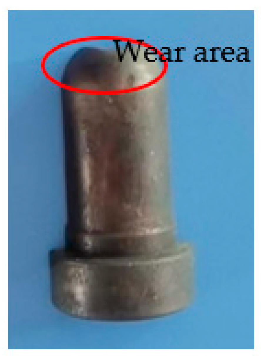
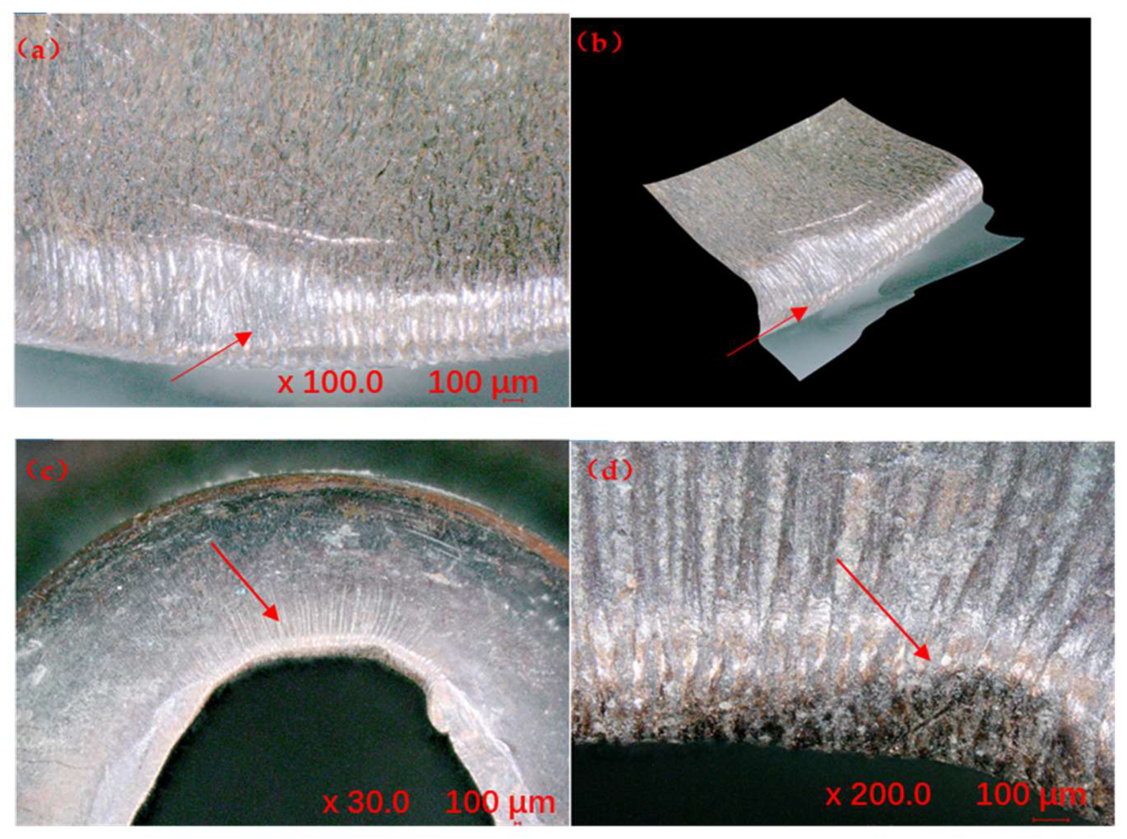
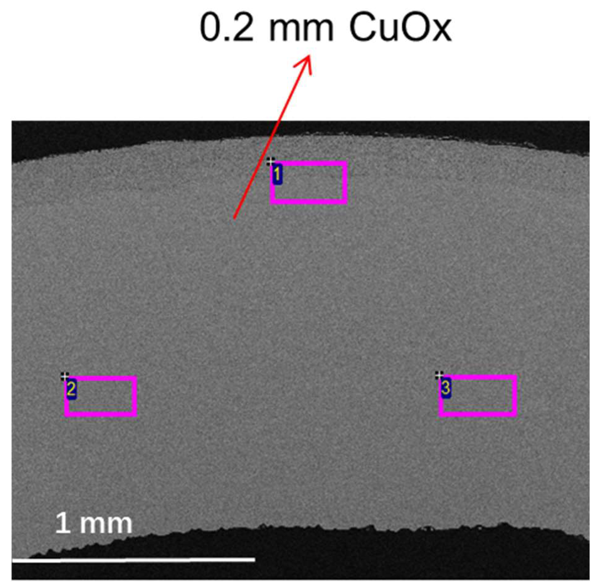
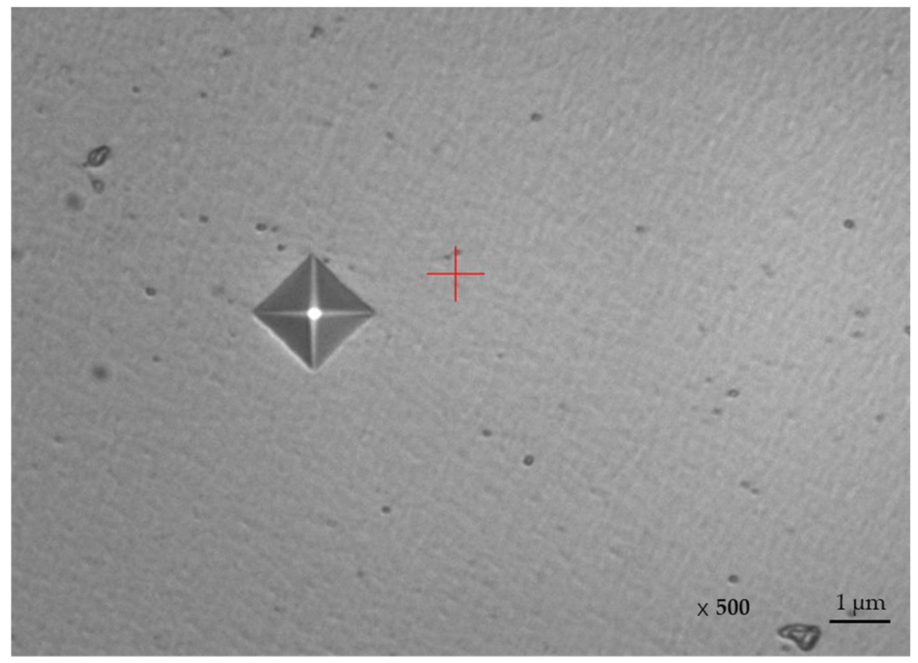
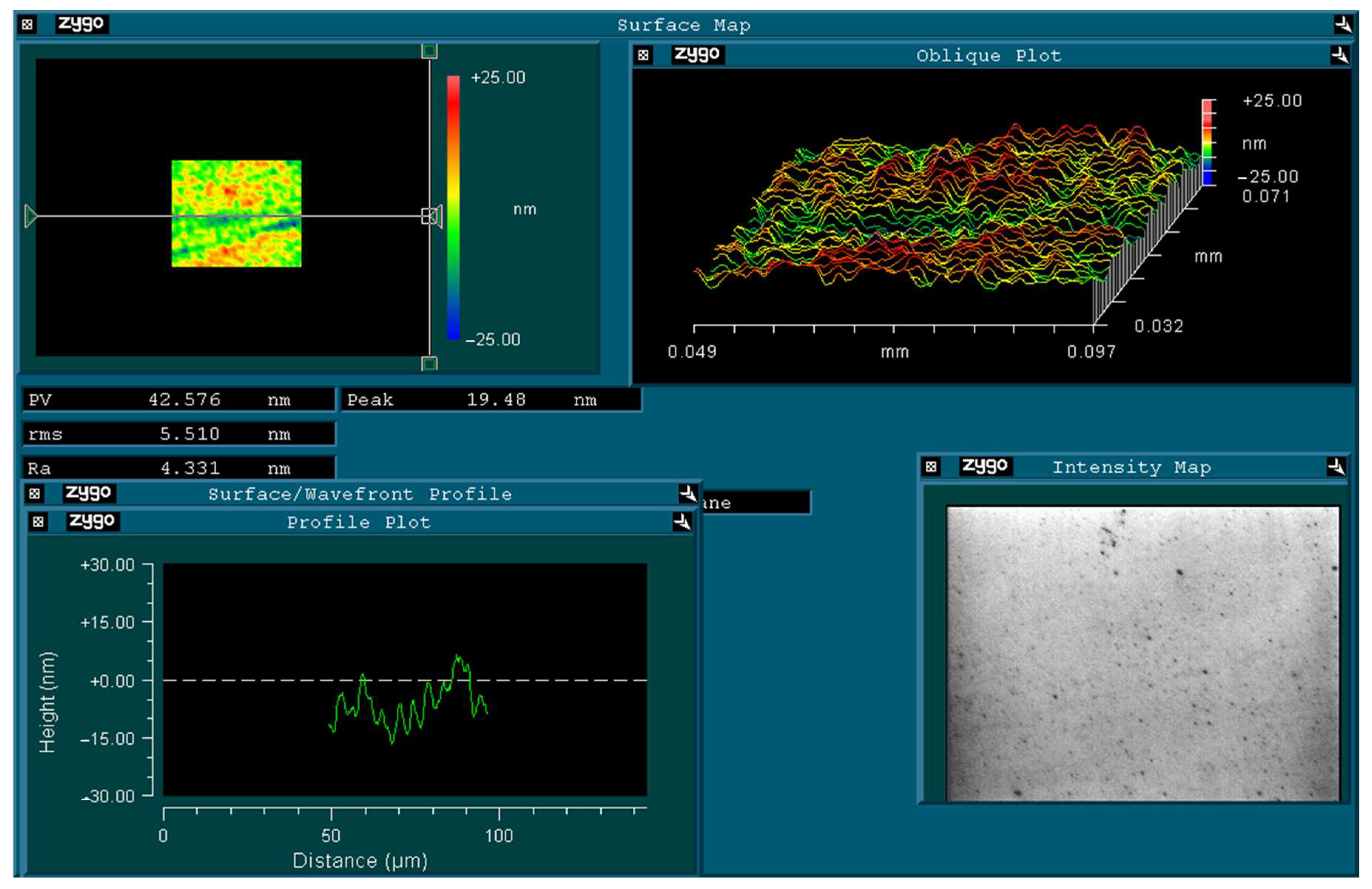
3.1. Detection and Analysis of Mold Wear Causes

High magnification microscopic images of the mold wear area are shown in Figure 4. Figure 4a shows the morphology of the mold wear area at 100 times magnification, while Figure 4b shows an overall view of the corresponding mold wear area. Figure 4c shows a 30× magnification of the wear area and Figure 4d shows a further 200× magnification. The optical microscope images show irregularities on the mold surface characterized by raised and recessed areas, streaks and arcuate patterns. The wear area shows significant expansion, pronounced local depressions or deeper regions and pronounced wear marks. In addition, the wear area appears to be relatively long.
During the wear process, observing the surface and subsurface characteristics of the mold plays a key role in understanding the wear mechanism. It can be seen from Figure 4 that the depth of the wear area is deep and shallow, which not only reflects the degree of wear of the mold material, but also reveals the nature of the wear mechanism. The shallower wear may be more due to surface wear caused by friction, while the deeper wear may involve the removal or plastic deformation of the mold material. For the surface wear caused by friction, the depth is usually shallow, mainly focused on the microscopic roughness of the mold surface. This type of wear is usually caused by friction and interaction between the mold and the workpiece, which results in a small amount of removal of the material on the mold surface. On the other hand, for wear that involves the removal of mold material or plastic deformation, the depth is usually deeper and may go deep into the subsurface of the mold. This type of wear can be caused by high stress, high thermal stress, or fatigue, which can lead to plastic flow, microcracks, or fractures in the mold material.
By observing the morphology of the wear surface, it is found that the wear surface presents scratches, furrows, plastic deformation and other characteristics, which may be caused by friction and adhesion. It is suggested that the microstructure may change in grain size and phase composition, which may be related to the high temperature behavior and heat treatment process of the material. A change in composition may appear as a change in element concentration or the formation of a new phase, which may be caused by corrosion, oxidation, or a phase transition of the material. In order to determine the type of wear, an SEM analysis of the worn area was carried out as shown in Figure 5. Figure 5a shows the image of the wear area magnified 17 times, while Figure 5b shows a magnification of 500 times.
The SEM images show clear evidence of melting in the wear area, indicating that the wear may be the result of melting or fusion of the material surface caused by high temperatures [29,30,31]. Figure 5a provides a 17× magnification, while Figure 5b provides a 500× magnification of the worn area. These images show that the worn area of the mold is uneven, with noticeable raised and recessed areas that form an adhesive shape. An adhesive shape refers to a type of shape deformation that occurs when a material is adhered to another surface. This deformation is typically caused by the application of a mechanical force that presses the material onto the other surface. It is speculated that there may be adhesive material or traces of melting on the surface [32,33,34,35]. In addition to melting, mold wear may also be affected by other factors. The following are other causes that may cause mold wear: (1) Surface fatigue: Under the action of cyclic load or alternating stress, the mold surface may produce fatigue cracks, which will lead to material peeling. This fatigue crack may be caused by internal defects of the material, stress concentration, improper heat treatment, and other factors. (2) Adhesive wear: Adhesive wear is caused by the adhesive force generated between two contact surfaces. When two contact surfaces are in relative motion, the adhesive force generated between them may cause one surface to be pulled onto the other, resulting in minor damage. This type of wear mainly depends on the difficulty of alloying and solid solution between the contact surfaces. In the process of friction between the mold and the workpiece, due to the action of friction, the mold surface may stick to the workpiece material, resulting in mold wear. The degree of adhesive wear may be affected by factors such as friction coefficient, workpiece material properties, die surface treatment, etc. (3) Impact wear: Under the action of impact or vibration, the mold surface may be subjected to impact wear. This impact wear may be caused by factors such as uneven hardness of the workpiece, unreasonable mold design, and unstable operating conditions. (4) Oxidative wear: under high temperature environment, oxidation reaction may occur on the mold surface to form an oxide layer. This oxide layer may reduce the wear resistance of the die surface, leading to increased wear. The degree of oxidative wear may be affected by the temperature, oxygen concentration, oxidation resistance of mold materials and other factors. The depth of the wear area varies, with noticeable localized depressions or deeper regions, indicating removal or frictional wear of the surface material. The length of the wear area is also significant and follows the path of movement of the adhesive material or worn surface, indicating the possibility of adhesive wear. (5) Abrasive wear: Abrasive wear is caused by hard particles or uneven surfaces. When the mold comes into contact with hard particles or uneven surfaces of the workpiece, these hard particles or uneven surfaces will produce scratches or cutting phenomena, which will wear the mold. Generally speaking, the greater the load, the greater the wear amount; the higher the hardness, the less wear [36]. The presence of raised and recessed areas, which form an adhesive shape, as well as the length of the wear area following the path of movement of the adhering material or worn surface, are strong indicators of adhesive wear. It seems highly likely that the wear observed on the copper-based mold is due to adhesive wear. Adhesive wear typically occurs when two surfaces come into contact and adhere to each other due to mechanical force or friction. In this case, the copper-based mold may have been subjected to sufficient mechanical force or friction during the molding process to cause the material to adhere to the mold surface. The resulting wear pattern, with raised and recessed areas along the length of the wear area, is a classic characteristic of adhesive wear. Given the above analysis, it is highly likely that the wear observed is adhesive wear [37,38].
When two contact surfaces of a tribological pair come into contact, there is point contact due to surface irregularities. With relative sliding and a certain load, plastic deformation or shearing occurs at the contact point, causing the surface films to break and the friction surface temperature to increase. In severe cases, the surface metal can soften or melt, resulting in adhesion at the contact point. This process leads to a cyclic occurrence of adhesion, shearing, re-adhesion and re-shearing, ultimately causing adhesive wear. In the presence of lubrication, adhesion can only occur when the oil film breaks down. On unlubricated surfaces, direct metal-to-metal adhesion can only occur when the surface contaminant films fail. The different degrees of adhesion give rise to different types of adhesive wear. When shearing occurs at the adhesive contact interface, minimal material transfer occurs, resulting in light wear. “Smearing” occurs when shearing occurs within the shallow layer of a soft metal and is transferred to the surface of a hard metal. “Scoring” refers to the scratching of the hard surface when shearing occurs in the near surface region of a soft metal. The term “delamination” is used when shearing occurs in the deeper regions of one or both metals in the tribological pair. When the tribological pair is locked and cannot move relative to each other, the term “seizure” is used [39,40].
Figure 6a shows the EDS examinations carried out on two points at a magnification of 2 mm: Point 1 represents the worn area, while point 2 characterizes the normal region. The elemental distribution is shown visually in Figure 7a,b and the measured results are documented in Table 1.
A comparison between the two data sets revealed changes in the elemental composition of the material throughout the wear process. In particular, a significant decrease in copper content was observed in the worn region, accompanied by an increase in carbon and oxygen content. In addition, the presence of several trace elements was detected, suggesting their relationship to the adhesive material under investigation. In order to gain a more complete understanding of the elemental composition within the worn area, three points were selected for EDS analysis at a higher magnification of 900× within the region of point 1 in Figure 6a, as shown in Figure 6b. Point 1 represents a sampled area of the worn edge depression, point 2 corresponds to the sampled area of the edge protrusion and point 3 represents a sampled area within the worn region. By taking measurements at these different points within the worn area and examining the possible composition of the bonding material, the results are summarized in Table 2, while the elemental distribution is shown in Figure 8a–c. It was observed that the copper content gradually decreased from point 1 to point 3, while the carbon content showed a corresponding increase. There was also a slight decrease in oxygen content. In addition, the presence of magnesium was detected at the edge of both point 1 and point 2.
For the X-EDS scanning test, as shown in Figure 9, three points were taken in different regions of the sample. The measured spectra are shown in Figure 10, while points 1, 2, and 3 correspond to (a), (b) and (c), respectively. From the spectrum, the four elements C, O, Al, and Cu can be determined. From the peak intensity and relative abundance of each element in the spectrum, the percentage content of each element in the sample can be determined as shown in Table 3.
X-EDS performs elemental analysis by scanning the X-rays produced by the electron-beam excited sample. The depth of the scan is measured. The EDS spectra were observed and analyzed for the intensity of the fluorescence peak. According to the test results, the copper in the sample was the main component. It accounted for approximately 92.20% of the total composition. In addition to copper, small amounts of carbon, oxygen and aluminum were also detected. These elements could be impurities in the sample. Their presence may be caused by factors such as the source of the sample, the preparation process or contamination.
For further analysis and comparison, XRF (cross-sectional X-ray fluorescence) is a non-destructive surface analysis technique. It uses an X-ray fluorescence spectrometer on the cross-section of the material, typically measuring the elemental content near the surface of the sample. The measured results are shown in Table 4. The sample is estimated to contain 98% Cu and 1% Si, with trace amounts of Co and Ni, in terms of the relative abundance or content of each element.
Combining the results of Figure 9 and Figure 10 and Table 3 and Table 4, the elements detected include copper (Cu), carbon (C), oxygen (O), and aluminum (Al), of which copper is the major component. Impurities include carbon, oxygen and aluminum, which may originate from sample sources, or contamination. The influence of these elements on the relationship between sample wear and damage mechanism may be as follows:
Copper (Cu): Copper is a metallic element with good electrical and thermal conductivity, copper alloys have excellent physical and mechanical properties such as high electrical conductivity, good thermal conductivity, high strength, and good corrosion resistance, so it is widely used in electronic equipment and construction. The hardness of copper is relatively low, so the mold surface may undergo plastic deformation during friction, resulting in local stress concentration and micro-crack initiation inside the mold. These micro-cracks may cause the mold surface to become rough, further increasing wear. The wear of copper alloy die is caused by a variety of factors, including mechanical stress, thermal stress, oxidation, etc.
Silicon (Si): The content of silicon is lower, but its hardness is higher, which may exacerbate scratches and peeling on the mold surface. In addition, the silicon may also react with the copper to form a harder compound, which further affects the wear resistance of the mold.
Carbon (C): Carbon is one of the common impurities in metals that can reduce the toughness and wear resistance of metals. During wear, carbon can aggravate scratches and flaking on the surface of the mold.
Oxygen (O): Oxygen can react with metal elements at high temperatures, causing oxidative wear on the tool surface. In addition, oxygen can exacerbate thermal fatigue crack propagation in the die. When the copper alloy die is heated to a high temperature, the surface of the die is oxidized to form an oxide layer, which reduces the hardness and strength of the die surface. In addition, if the oxide layer is subjected to cyclic stress or thermal shock, it will separate from the die surface, resulting in wear.
Aluminum (Al): Aluminum is a light, high-strength metallic element, but it can reduce the toughness of the metal. During wear, aluminum can exacerbate scratches and flaking on the mold surface.
In addition, the XRF results also showed that the samples contained trace amounts of cobalt (Co) and nickel (Ni). Although neither element was detected in the EDS results, they both have a potential impact on the wear resistance of the mold. Both cobalt and nickel have a high hardness, they may form hard spots or tiny particles on the surface of the mold, causing the surface of the mold to scratch or flake more easily, which may exacerbate scratches or flaking on the die surface.
In summary, although the EDS and XRF results differ in the measurement of some elements, they all indicate that the copper, silicon, cobalt and nickel elements in this sample have an effect on the wear of the copper alloy die. Copper can form hard spots or hard phases in the material, making the mold surface more susceptible to scratching or flaking. Elements such as carbon and aluminum can increase the hardness of the material, further increasing wear and cracking. Oxygen can reduce the toughness of a material, making it more susceptible to cracking or fracture under impact or cyclic loading. Elements such as oxygen and copper can oxidize at high temperatures to form an oxide layer, which can cause the mold surface to become rough or peel, further increasing wear. Elements such as carbon, oxygen, and aluminum can be present in the material as impurities, perhaps from the materials being cast, and these impurities can form tiny defects in the material, such as micro-cracks or holes, which can expand into larger cracks.

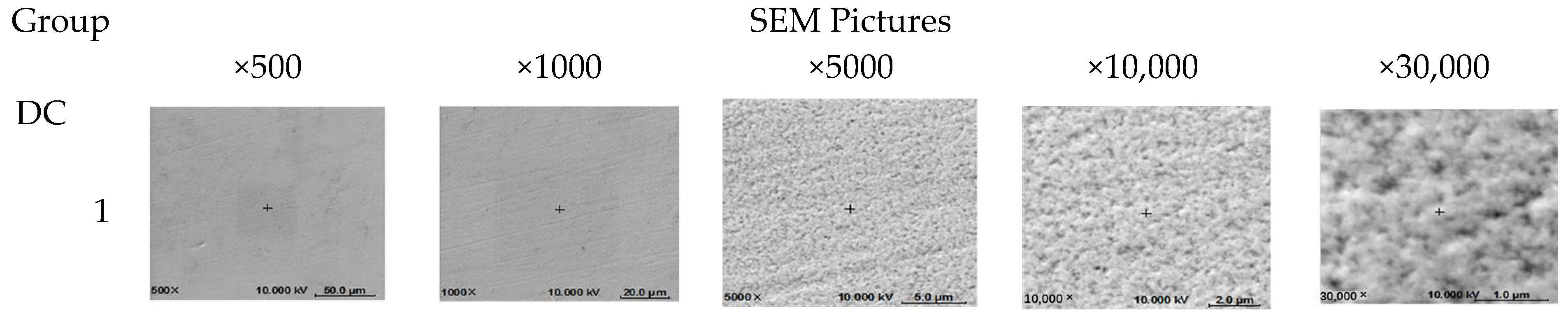
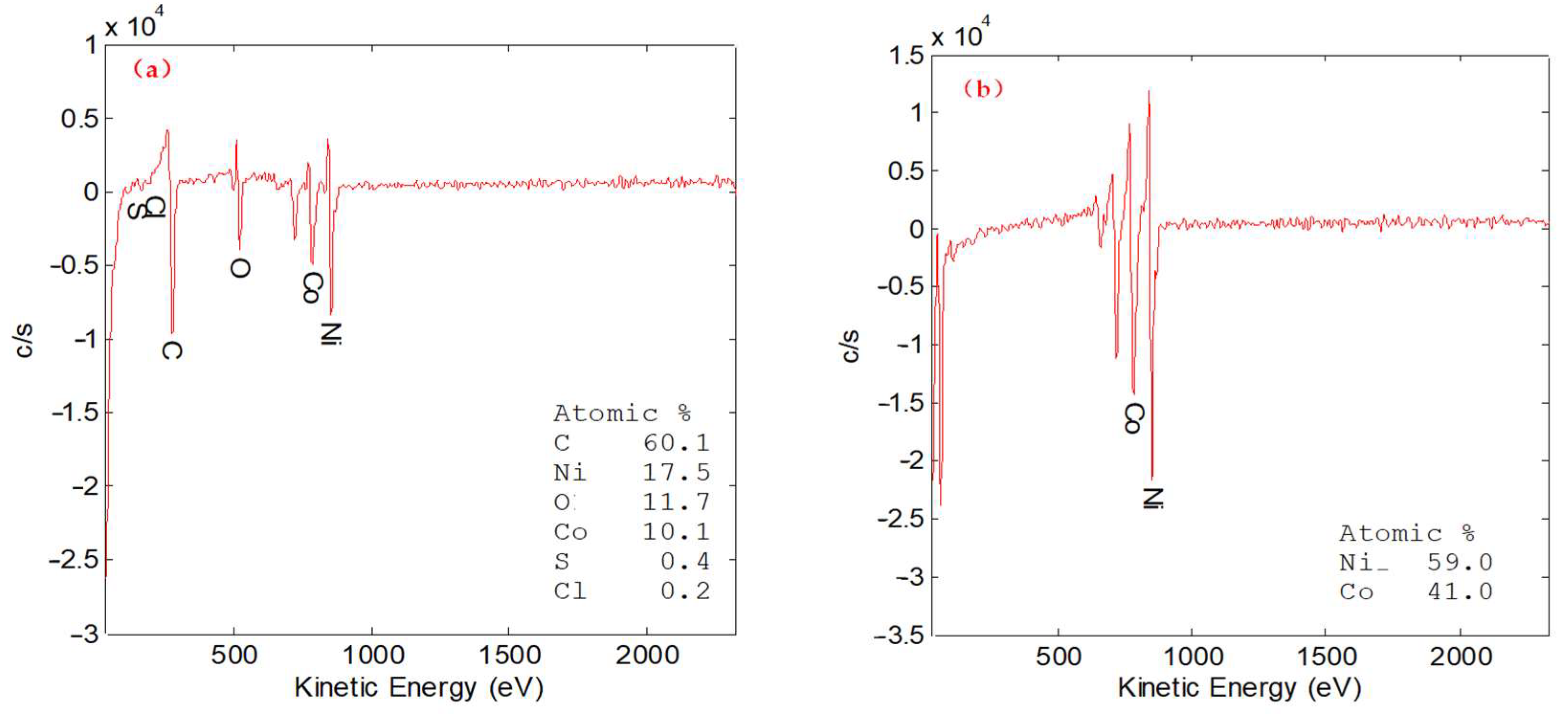
3.2. Experiment and Performance Comparison of Ni Cocoatings Prepared by Different Power Sources

There is a great deal of literature on how coating the mold surface can significantly improve the wear resistance of the mold. To improve the wear resistance of molds in high temperature and high stress environments, the selection of appropriate mold materials and coatings is essential. Ni-Co alloy coating prepared by electrodeposition is an effective method to increase the wear resistance on the surface of copper alloy die. To obtain a good quality NiCo coating, by reading the comparative references in detail [41,42,43,44], we adjusted the Ni-Co weight ratio to 80:20, 60:40 and 40:60, and used DC power electroplating and double pulse power electroplating for coating comparison.
The experiment conditions are listed in Table 5, and the physical properties of each group of samples were tested as follows: three points for hardness, three points for thickness and three points for roughness, and the results are shown in Table 5.
As can be seen from Table 5, under the same conditions, the coating hardness prepared by pulsed power supply is significantly higher than that of DC power supply group, with an average of about 30% higher, an average of 450% higher thickness, and an average of 14% lower roughness. Among them, the fifth group had the highest average hardness value of 465.257 HV when the NiCo weight ratio was 60:40. The average thickness was 34.081 um. Wear resistance is significantly influenced by the hardness of the NiCo (nickel-cobalt) coating [45,46]. The ability to resist surface wear and plastic deformation can be determined by the hardness of the coating. When the hardness of the NiCo coating is high, the surface of the coating is more resistant to scratching and can effectively resist external scratching and friction. Such coatings can provide better wear resistance for components that suffer from scratched or abraded surfaces, protecting the substrate from damage. On the other hand, the high hardness NiCo coating can resist friction and wear, thus reducing the surface wear and mass loss. The harder the coating, the better it can maintain surface integrity and smoothness under external friction, improving the wear resistance of the material. The high hardness NiCo coating also has a high resistance to plastic deformation. This prevents the coating from warping, peeling or flaking. When the hardness of the coating is high, the coating is better able to maintain its original shape and structure, providing better wear resistance and extending the life of the coating.
Combined with the hard test, thickness, and roughness results comparison, the morphology of the coatings obtained from each group was meticulously analyzed. As illustrated in Figure 11, the SEM group diagram demonstrates that the coating fabricated using a pulse power supply exhibits distinct microstructural and surface morphological differences compared to the one prepared via a DC power supply. Notably, the coating generated by the pulse power supply (refer to Figure 11, pulse group (4–6)) demonstrates a significantly higher degree of compactness. In the SEM images, the coating appears relatively uniform and compact, with scarce pores and cracks, particularly in Figure 11 group (5).
The coating prepared by the DC power supply in Figure 11 DC group (1–3) exhibits a higher density of pores, cracks, or bumps, as compared to the coating generated by the dual pulse power supply, which is evident in Figure 11 Pulse group (4–6). The surface of the latter is shown to be relatively more uniform, as observed in the scanning electron microscope (SEM) images. Upon examining the SEM images of each group, it becomes clear that the morphology of the coating varies slightly across the entire surface in pulse group, in contrast to the varying uneven morphology observed in the DC group. Furthermore, the surface texture characteristics of the pulse group coating, characterized by prominent granules and a relatively smooth surface, can be observed in the SEM image, which is consistent with the conclusion that the coating roughness of pulse group is lower than DC group.
The fifth group of coatings were analysed and tested using AES: PHI710 AES, electron gun: electron beam voltage: 10 kV; electron beam current: 10 nA; Figure 12a shows the atomic analysis of the surface. The results show that inorganic elements such as C, O, S, and Cl are present in addition to Ni and Co. After sputtering the sample for 3 min, the AES results in Figure 12b show that the atomic ratio of Ni:Co is close to 60:40. This is in agreement with the experimental conditions.
The experiment is repeated in the same conditions. The measured SEM diagram is shown in Figure 13 as follows:
The SEM images showed that the surface of the Nico coating was dense and smooth under these conditions. This indicates that the preparation method of the coating may have produced the expected effect. The hardness test results are shown in Figure 14. The result of the hardness test is 474 HV, which shows that the coating has a relatively high hardness, indicating that it has good wear and corrosion resistance.
The coating was tested using a Zygo thickness gauge. The results are shown in Figure 15. The thickness is 43.0665 μm, which indicates that the coating has a certain thickness and may provide sufficient protection for the substrate. The surface roughness is shown in Figure 16. The result is 4.331 nm, which indicates that the surface of the coating is very smooth, which is important for some high-precision applications.
The wear resistance of the wear layer is evaluated by the wear test module of the nanoindentation instrument, TI 950 TriboIndenter, Hysitron Co. Ltd., Eden Prairie, MN, USA, load, 30 μN, wear area of 4 μm × 4 μm, which uses a diamond indenter to rub back and forth over a specified area to remove the coating. All samples use the same test parameters, including the loading force of the indenter. The unit of wear depth is nm, and a negative sign means that the material is removed. The wear resistance of the mold with coating is −28.7 nm. This is 80% higher than that of the original mold, −142.4 nm.
A comparison chart of the wear resistance test is shown in Figure 17. According to the test results of coating properties obtained by repeated experiments under the best conditions, the Ni-Co weight ratio is 60:40 and the double pulse power peak current is 1.5 A. Ton was set to 0.2 ms and Toff was set to 0.8 ms, a 10 min electroplating process, a good-quality NiCo coating with a thickness of 43.0665 μm, a hardness of 474 HV, and a roughness of 4.331 nm, and the wear resistance of the mold was increased by 80%.

4. Conclusions

In this paper, we analyzed the wear mechanism of the mold, analyzed the wear zone of the mold by high-power microscope and scanning electron microscope (SEM), and compared the elemental composition of the wear zone with the normal zone by energy dispersion spectrometer (EDS) and X-ray fluorescence spectrometer (XRF). The results show that the wear mechanism of the die is mainly adhesive wear. In order to solve the problem of mold wear, we tried to prepare a NiCo coating on the surface of the copper substrate. The samples were prepared by a DC power supply and a double pulse power supply, respectively. The morphology of the sample was analyzed and tested by SEM, and it was found that the surface coating of the sample prepared by a double pulse power supply was relatively dense. When the NiCo weight ratio is 60:40, the average hardness and thickness of the sample are the highest, and the standard deviation results show that the dispersion is small and the roughness is low. Under the same conditions, the experimental repeatability test shows that the coating surface is dense and uniform, the hardness is 467.628 hv, the thickness is 43.0665 μm, and the roughness is 4.331 nm. Nanoindentation test results show that the wear resistance of the coating is −28.7 nm, which is 80% higher than the original mold.
The results of this study show that the preparation of NiCo coating on the surface of copper substrate by double-pulse power plating technology is an effective method to improve the wear resistance of dies. When the weight ratio of NiCo is 60:40, the hardness and thickness of the sample reach the maximum value, the surface morphology of the coating is dense and uniform, the roughness is low, and the wear resistance is obviously better than that of the original mold. These findings are of great significance for understanding the problem of mold wear and its application in practical production.
Through the study of this paper, we draw the following conclusions:
(1)
The wear mechanism of the die is mainly adhesive wear.
(2)
The NiCo coating prepared on the surface of copper substrate by double pulse power electroplating technology has higher density and uniformity, and can effectively improve the wear resistance of the die.
(3)
When the NiCo weight ratio is 60:40, the hardness and thickness of the sample reach the maximum, and the wear resistance of the coating is the best.
(4)
The results of this study provide an effective coating preparation method to solve the problem of mold wear, which is helpful to improve the service life and production efficiency of the mold.
These conclusions not only have important value in understanding the mechanism of die wear but also provide a theoretical basis and practical guidance for the application of coating technology to solve the problem of die wear in actual production. In the future, the effects of different element combinations and process parameters on coating properties, as well as the applicability of coatings on different types of mold materials, can be further discussed to provide more references for expanding the application of coating technology in the field of mold.

Author Contributions

Conceptualization, X.J.; methodology, X.J.; software, X.J.; validation, X.J. and F.K.; formal analysis, X.J.; investigation, X.J.; resources, X.J.; data curation, X.J.; writing—original draft preparation, X.J.; writing—review and editing, X.J.; visualization, X.J.; supervision, X.J.; project administration, X.J.; funding acquisition, X.J. All authors have read and agreed to the published version of the manuscript.

Funding

This research was funded by the Natural Science Foundation of Guangdong Province China, grant number 2023A1515012309 and by the sci-tech commissioner project of Dongguan, grant number 20221800500152.

Institutional Review Board Statement

Not applicable.

Informed Consent Statement

Not applicable.

Data Availability Statement

Data are contained within the article.

Acknowledgments

SAE Magnetics (HK) Ltd.

Conflicts of Interest

The authors declare no conflict of interest.

References

  1. El-Naggar, M.I.; El-Sayed, M.A. Wear mechanisms in sliding wear: A review of the state-of-the-art. J. Mater. Eng. Perform. 2020, 29, 1369–1385. [Google Scholar]
  2. Nemat-All, N. Investigation of wear mechanisms in sliding contact using numerical simulation. Wear 2022, 457, 149–158. [Google Scholar]
  3. Khoshnevisan, A.; Rezaei, M. A study on the wear mechanisms of low carbon martensitic steels under sliding conditions. Mater. Des. 2023, 187, 108–115. [Google Scholar]
  4. Gupta, P.; Gupta, A. A study on the wear mechanisms of tribological interfaces in reciprocating motion. Wear 2022, 435, 209–218. [Google Scholar]
  5. Zhang, S.; Wang, H.; Wang, C. Effects of surface integrity on wear mechanisms in rolling contact fatigue failure of a bearing steel. Wear 2022, 457, 95–104. [Google Scholar]
  6. Kimura, Y. Friction and Wear at the Initial Stage: Effects of Surface Roughness and Sliding Speed. Wear 1996, 192, 115–124. [Google Scholar]
  7. Zhang, S.; Wang, H.; Wang, C. Effects of surface treatment on wear mechanisms in copper alloy dies. Wear 2022, 457, 75–84. [Google Scholar]
  8. Dogan, I.; Senthilkumar, H. Study on wear mechanisms of copper alloy dies in precision stamping. Int. J. Adv. Manuf. Technol. 2023, 108, 907–916. [Google Scholar]
  9. Gao, L.; Li, Q. Study on wear mechanisms of copper alloy molds for automobile components. Mater. Des. 2023, 188, 897–915. [Google Scholar]
  10. Lee, S.; Zhang, J. Investigation of wear mechanisms in copper alloy molds under sliding contact conditions. Wear 2022, 457, 119–128. [Google Scholar]
  11. Pai, S.; Naik, S.P. Investigation of wear mechanisms in copper alloy molds. J. Mater. Process. Technol. 2022, 201, 25–34. [Google Scholar]
  12. Zhang, W.; Li, Y. Study on wear mechanisms of copper alloy molds under different temperatures. Int. J. Adv. Manuf. Technol. 2023, 108, 2359–2371. [Google Scholar]
  13. Wang, X.; Zhang, J. Analysis of wear mechanisms in copper alloy molds using numerical simulation. Wear 2023, 458, 159–168. [Google Scholar]
  14. Yang, J.; Liu, Q. Experimental investigation of wear mechanisms in copper alloy molds under high-speed impact conditions. Mater. Des. 2023, 184, 106995. [Google Scholar]
  15. Pinto, A.R. Study of wear mechanisms in copper alloy molds during injection molding. J. Mater. Process. Technol. 2011, 289, 1–11. [Google Scholar]
  16. Zhang, L.; Li, Y. An analysis of wear mechanisms in copper alloy molds used for plastic injection molding. Int. J. Adv. Manuf. Technol. 2023, 110, 2359–2371. [Google Scholar]
  17. Yang, J.; Wang, Z. A study on the wear mechanisms of copper alloy molds in medical injection molding. J. Biomater. Nanobiotechnol. 2023, 14, 609–621. [Google Scholar]
  18. Zhou, W.; Zhang, X. Investigation of wear mechanisms in copper alloy molds used for electric motor components. J. Mater. Sci. Technol. 2023, 38, 1093–1104. [Google Scholar]
  19. Al-Sayed, A. Study on the Wear Behavior of Copper Alloy Dies in Plastic Injection Molding. J. Mater. Process. Technol. 2017, 250, 195–204. [Google Scholar]
  20. Zhou, Y.; Wang, H. A study of wear mechanisms in sliding wear using a combined experimental and numerical approach. Wear 2013, 297, 598–610. [Google Scholar]
  21. Li, Y. Research on the Prevention and Repair of Copper Alloy Die Wear in Plastic Injection Molding. Mater. Des. 2016, 89, 179–188. [Google Scholar]
  22. Gupta, M. Effect of Process Parameters on Copper Alloy Die Wear in Plastic Injection Molding. J. Mater. Process. Technol. 2017, 239, 181–189. [Google Scholar]
  23. Chen, Y.; Ma, H.; Zhang, Q. Preparation of Ni-Co alloy coating by pulse electrodeposition and its effect on the fracture of mold material. Appl. Surf. Sci. 2017, 426, 531–537. [Google Scholar]
  24. Li, X.; Shen, Y.; Zhang, X. The research of pulse electrocodeposition Ni-Co coating on the application of automobile panel mould. Surf. Coat. Technol. 2019, 357, 906–918. [Google Scholar]
  25. Yan, L.; Guo, H.; Cui, X.; Li, S.; Wang, Y. Corrosion and Wear Resistance of Ni–Co Alloy Coatings Prepared by Copper Electroplating Method. J. Mater. Eng. Perform. 2018, 27, 2798–2806. [Google Scholar]
  26. Liu, K.; Wang, Y.; Zhao, Y.; Li, S. Influence of Co content on microstructure and corrosion resistance of Ni–Co alloy coatings prepared by copper electroplating method. Surf. Coat. Technol. 2017, 315, 116–122. [Google Scholar]
  27. Kalsi, S.S.; Gupta, S.K. Prediction of Die Wear in Plastic Injection Molding Using Artificial Neural Networks. Adv. Mater. Res. 2011, 428, 254–262. [Google Scholar]
  28. Cai, Z.Y. Study on Mechanical Properties and Friction and Wear Characteristics of Nanostructured Nickel-Cobalt Alloys by Electrodeposition. Master’s Thesis, Jilin University, Changchun, China, 2020. [Google Scholar]
  29. Wang, Y.; Zhang, L.; Li, Z. Understanding wear mechanisms in sliding bearings using finite element analysis. J. Tribol. 2019, 141, 021601. [Google Scholar]
  30. Li, P.; Liu, L.; Wu, J. Study of wear mechanisms in sliding contacts using tribometers and numerical simulations. Wear 2018, 360, 60–73. [Google Scholar]
  31. Johnson, K.L.; Xie, Z. Wear mechanisms in sliding contacts: A review of the current knowledge and future challenges. J. Lubr. Technol. 2017, 139, 031502. [Google Scholar]
  32. Gupta, M.; Srivastava, A. Modelling of wear mechanisms in sliding bearings using finite element analysis. J. Mech. Eng. Sci. 2016, 230, 1495–1510. [Google Scholar]
  33. Li, M.; Wu, J. Understanding and predicting wear mechanisms in sliding systems using advanced experimental and numerical techniques. Wear 2015, 338–339, 80–93. [Google Scholar]
  34. Sun, Y.; Zhang, X.; Wang, Y. Wear mechanisms in sliding contacts: Influence of surface roughness and contact pressure. Tribol. Int. 2014, 78, 28–37. [Google Scholar]
  35. Xu, Y.; Zhang, L. Wear mechanisms and their prevention in sliding bearings: A review. J. Mech. Eng. Sci. 2012, 226, 945–964. [Google Scholar]
  36. Rabinowicz, I.; Tobias, A. Sliding wear: A review of mechanisms and effects of surface roughness and lubrication conditions. Wear 2011, 271, 1639–1657. [Google Scholar]
  37. Gao, D.; Li, Y.; Wang, Z. Effects of surface roughness on adhesive wear of steel in sliding contact. Wear 2019, 336, 105–113. [Google Scholar]
  38. Li, J.; Zhang, Y.; Wang, Z. Adhesive wear behavior of low-carbon steel under sliding contact fatigue loading. Mater. Des. 2018, 153, 375–384. [Google Scholar]
  39. Zhang, L.; Li, Y.; Wang, Z. Study on the adhesive wear mechanism of steel in sliding contact with different counterpart materials. Wear 2020, 371–372, 205–214. [Google Scholar]
  40. Guo, H.; Yan, L.; Li, S.; Zhang, L.; Wang, Y. Effect of electrodeposition temperature on the morphology, microstructure and properties of Ni–Co alloy coatings prepared by copper electroplating method. J. Mater. Sci. Technol. 2016, 32, 233–240. [Google Scholar]
  41. Xia, X.; Zhang, X. Tribological Property of Ni–Co Alloy Coatings Prepared by Copper Electroplating Method. J. Mater. Eng. Perform. 2018, 27, 3540–3548. [Google Scholar]
  42. Wang, Y.; Li, S.; Zhao, Y.; Zhang, L. Preparation and characterization of Ni–Co alloys by electrodeposition using different reverse pulse voltages. Int. J. Electrochem. Sci. 2014, 9, 6595–6604. [Google Scholar]
  43. Ma, J.; Zhang, B.; Ma, Y. Preparation and tribological properties of Ni–Co/SiC composite coatings by copper electroplating method. J. Mater. Sci. Technol. 2019, 35, 1375–1384. [Google Scholar]
  44. Guo, H.; Yan, L.; Li, S.; Wang, Y. Effect of Copper Concentration on Electrodeposition of Ni-Co Alloy Coatings Prepared by Copper Electroplating Method. J. Mater. Eng. Perform. 2014, 23, 4213–4220. [Google Scholar]
  45. Wang, Y.; Yan, L.; Li, S.; Guo, H.; Fu, H. Study on the Microstructure and Properties of Ni-Co Alloys Deposited by Copper Electroplating Method at Low Temperature. Trans. Chin. Soc. Agric. Mach. 2013, 44, 300–305. [Google Scholar]
  46. Luo, J.; Zhang, Y.; Wang, J. Preparation and corrosion resistance of Ni–Co coatings by electrodeposition using pulse current. Trans. Nonferrous Met. Soc. China 2018, 28, 2345–2353. [Google Scholar]
Figure 1. General wear process (Oa shows Stage I, Running-in stage; ab shows Stage II, stable wear stage; Stage III is Rapid wear stage).
Metals 13 01933 g001
Figure 2. Runner needle valve nozzles worn mold.
Metals 13 01933 g002
Figure 3. (a) Thickness test schematic diagram. (b) Roughness test schematic diagram.
Metals 13 01933 g003
Figure 4. Optical microscope images depicting the worn area at different magnifications. (a) 100×, (b) overall view, (c) 30×, (d) 200×. The red arrows indicate the same wear locations corresponding to different magnifications.
Metals 13 01933 g004
Figure 5. SEM image (a) magnified 17 times and image, (b) magnified 500 times. The red arrow indicate the same wear locations corresponding to different magnifications.
Metals 13 01933 g005
Figure 6. (a) The selected measuring points (pink squares) in the worn area and the unaffected area at a magnification of 2 mm. (b) The selected measuring points (pink squares) in the worn area at a magnification of 900 μm.
Metals 13 01933 g006
Figure 7. (a) Elemental distribution map corresponding to point 1. (b) Elemental distribution map corresponding to point 2.
Metals 13 01933 g007
Figure 8. (a) Elemental distribution map corresponding to point 1. (b) Elemental distribution map corresponding to point 2. (c) Elemental distribution map corresponding to point 3.
Metals 13 01933 g008
Figure 9. Mold surface sampling. Pink squares shows different locations. The red arrow shows the main component of the surface is 0.2 mm CuOx.
Metals 13 01933 g009
Figure 10. EDS spectrum diagrams (a) Spectrum 1, (b) Spectrum 2 and (c) Spectrum 3.
Metals 13 01933 g010
Figure 11. SEM of each group at different magnifications.
Metals 13 01933 g011aMetals 13 01933 g011b
Figure 12. Comparison of AES results (a) the atomic analysis of the surface, (b) the atomic analysis after sputtering 3 min.
Metals 13 01933 g012
Figure 13. SEM images of best condition magnification times. (a) 1000×, (b) 5000×, (c) 10,000×, (d) 30,000×.
Metals 13 01933 g013
Figure 14. Diagram of the hardness test.
Metals 13 01933 g014
Figure 15. Thickness measuring. Dotted lines are for reference.
Metals 13 01933 g015
Figure 16. Surface roughness measuring. Dotted lines is for reference.
Metals 13 01933 g016
Figure 17. Comparison chart of wear resistance test. (a) Sample from mold (b) Sample from prepared coating. The red squared area is the comparison test area.
Metals 13 01933 g017
Table 1. Comparison of EDS results for different regions.
COMgAlSiPSClKCaFeCu
146.3311.6000.190.4500.450.230.280.411.6138.72
218.468.8400000000072.70
Table 2. EDS results corresponding to different points in the wear area.
NGCOMgAlSiPSClKCaFeCu
125.2419.970.140.170.280.190.140.1500.231.6451.84
231.0119.280.100.140.280.100.180.770.310.394.1143.32
344.1210.9600.290.860.130.080.120.180.601.1741.49
Table 3. EDS Elemental Percentage Results.
Spectrum-%wtCOAlCu
15.316.980.3987.32
24.101.370.1894.34
33.851.050.1694.94
Mean4.423.140.2492.20
Standard. deviation0.783.340.134.24
Max.5.316.980.3994.94
Min.3.851.050.1687.32
Table 4. XRF results.
FeCuSiMnCrCoNi
(wt)%/98.3191.234//0.3660.081
Table 5. Comparison of the experimental conditions, the hardness, the thickness and the roughness results of each group.
ConditionValuePower Supply ModeSample Group No.Ni-Co Weight RatioHardnessThicknessRoughness
Average/HVStandard DeviationAverage/μmStandard DeviationAverage/nmStandard Deviation
Electric Current Density1.5 ADirect Current180:20298.9788.5521.8470.0799.1221.383
260:40307.6576.8198.3170.5955.0630.454
340:60313.9301.1747.7541.6126.3380.496
PH3 Pulse peak current
(Ton = 0.2 ms,
Toff = 0.8 ms)
480:20360.6761.66032.4950.1075.0360.315
Time10 min560:40465.2572.51634.0810.7084.7370.574
Volume500 mL640:60417.4240.63332.9060.8287.8550.346
Disclaimer/Publisher’s Note: The statements, opinions and data contained in all publications are solely those of the individual author(s) and contributor(s) and not of MDPI and/or the editor(s). MDPI and/or the editor(s) disclaim responsibility for any injury to people or property resulting from any ideas, methods, instructions or products referred to in the content.

