Abstract
We present a strategy for fabricating aluminum (Al) matrix composites (AMCs) reinforced with interconnected aluminum nitride (AlN) via arc plasma-induced accelerated volume nitridation. AMCs with 10 vol.% AlN are formed in situ by the reaction between liquid Al alloy and nitrogen gas within 1 min of arc melting, revealing very high formation rate of AlN (3.28 × 10⁻¹ g/min·cm3). The rapid nitridation is attributed to the improved wettability and spontaneous infiltration of the melt, which results in the formation of AlN agglomerates and lamellas. In particular, Al-12Si/AlN composites exhibit over two times higher yield strength (195 MPa) than the Al/AlN composites (70 MPa) when compressed along the longitudinal direction to the lamellas. The coefficient of thermal expansion (CTE) is about 30% lower in the Al-12Si/AlN composites (17.0 × 10⁻⁶/K) than pure Al (23.6 × 10⁻⁶/K). This is attributed to the interconnected AlN architecture and Al–Si eutectic microstructure, which constrain the thermal expansion of the Al matrix. The present AMCs afford an attractive combination of specific thermal conductivity and CTE. These findings would facilitate the development of novel AMCs reinforced with interconnected AlN as cost-effective heat sink materials.
1. Introduction
Owing to the electrification of automotive powertrains and the miniaturization of electronic devices over recent decades, the thermal management industry has shown considerable interest in novel heat-dissipation materials with high thermal conductivity (TC) and low coefficient of thermal expansion (CTE) [1,2]. Pure aluminum (Al) and Al alloys have been widely adopted for heat sink applications, owing to their high specific strength, high TC, and excellent deformability [1,3]. However, the CTE mismatch between the Al heat sinks (~23.6 × 10⁻⁶/K) and heat sources (4–8 × 10⁻⁶/K in GaAs, GaN, and Al2O3 [4]) must be reduced to relieve the thermal stress at the interface during the thermal cycle [5]. To satisfy the requirements of heat sink applications, various types of reinforcements with high TC, such as B4C [6], C fibers [7], CNT [8], and SiC [9,10,11], have been utilized to develop novel Al matrix composites (AMCs) [12]. However, the formation of the carbide phase (Al4C) at the interface is the main concern in carbide (carbon)-reinforced AMCs and should be avoided to prevent the degradation of thermal and mechanical properties.
Aluminum nitride (AlN) is a promising reinforcement for AMCs because of its low CTE, high TC, and thermodynamic compatibility with the Al matrix [13,14,15,16,17,18,19,20]. Various AMCs reinforced with AlN have been fabricated using ex situ processing techniques, such as stir casting [21] and pressure infiltration [22]. However, AlN exhibits unsatisfactory wettability with Al [23,24,25], which can result in weak interfacial bonding or debonding during composite processing. Strong interfacial bonding and excellent wettability between AlN and Al can be achieved by adding alloying elements such as Mg [21,26]; however, the TC of the Al matrix deteriorates significantly as the amount of solute in the Al matrix increases. Thus, in situ processing using pure Al has received considerable attention for achieving AMCs with high TC. Various techniques, such as directed melt nitridation [27], gas bubbling [28], surface nitridation [17], and plasma nitriding [13,16,19], have been introduced to fabricate AlN-reinforced AMCs with strong interfacial bonding.
Among the various in situ processing routes to fabricate AlN ceramics or AlN-reinforced AMCs, plasma processing has been utilized for nitriding treatment [29] and the preparation of ultrafine nitride powder [19]. AlN coating on Al substrates exhibited a thickness of ~10 μm [30], and ultrafine AlN powder with an average diameter of ~50 nm has been reported [16], which is not ideal for thermal management applications because the thermal properties of AMCs benefit from the high fraction and large size of the reinforcement. Recently, the in situ fabrication of bulk Al/AlN composites with reinforcement sizes in the micrometer range was investigated using thermal plasma via gas tungsten are welding [31] and arc melting [13]. Al/AlN composite ingots with widths of 20 mm were produced by arc melting via an arc plasma-induced accelerated volume nitridation (APAVN) process using pure Al and N2 gas [13]. The arc-melted Al/AlN ingots showed a much higher formation rate of AlN than other in situ processing techniques, thus enabling the further development of the APAVN process for cost-effective processing when the processing conditions are optimized accordingly. However, the composite microstructure and microstructural evolution of Al/AlN ingots during APAVN are rarely investigated.
Al-Si alloys such as A356 (Al-7Si) and A383 (Al-11Si) have been used for AMCs as matrix materials due to their high specific strength and excellent fluidity [32]. Recently, due to the high TC (150 W/m·K) and low CTE (2.2 × 10⁻⁶/K [14]) of Si, Al-Si alloys and Si particle reinforced AMCs with high Si content have attracted significant interest in the thermal management [33]. The strength of Al-Si alloys can be improved as the Si content increases, but the addition of Si higher than eutectic composition leads to the formation of blocky Si phase which is associated with the brittle nature of hypereutectic Al-Si alloys [32,34]. Thus, a eutectic Al-Si alloy (Al-12Si) can be one of promising matrix materials with high strength, moderate ductility, high TC and low CTE [35,36] which are required for heat sink applications.
In this study, we investigate the in situ formation of Al/AlN composites with an interconnected architecture of AlN via the APAVN of pure Al melt using nitrogen (N2) gas. In addition to this, the APAVN of an Al-12Si alloy is conducted to investigate the effect of Si addition on the AlN formation, microstructure, and mechanical/thermal properties of resulting composites. Within 1 min of the APAVN process, AMCs reinforced with 10 vol.% AlN are fabricated via the initial surface nitridation at a relatively low temperature, followed by volume nitridation at a relatively high temperature, which is assisted by the improved wettability and upward infiltration of the Al melt. The distinctive interconnected structure and the resultant thermal properties of the AlN-reinforced AMCs are systematically characterized. In particular, the microstructural evolution of Al/AlN composites during APAVN is discussed.
2. Experimental
Al and Al–12Si (at.%) alloys were prepared using pure Al and Si pieces (99.999% purity). Button-shaped Al and Al–12Si ingots (8 g in weight) were prepared using an arc melting apparatus equipped with a tungsten electrode in a Ti-gettered Ar atmosphere (60 kPa, 99.999% purity), as shown in Figure 1a,b. The ingots were nitrided via arc melting at an arc current of 150 A under a mixture of Ar and N2 atmosphere (Ar/N2 volume ratio = 2:1; total pressure = 60 kPa) [13], which resulted in the in situ formation of AlN in liquid Al during the melting and the fabrication of Al/AlN and Al–12Si/AlN composite ingots. The distance between the tungsten electrode and ingots was fixed at approximately 3 mm.
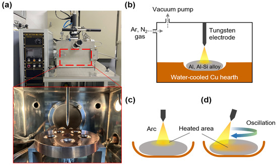
Figure 1.
(a) Images of arc melting apparatus and (b) schematic diagram showing the arc melting process. Nitridation of button-shaped ingot with a (c) fixed and (d) oscillating tungsten electrode in a circular motion.
In this study, Al and Al–12Si ingots were nitrided using a (1) fixed or (2) oscillated tungsten electrode. Using a fixed electrode (Figure 1c), an ingot placed on a water-cooled Cu hearth was locally heated via arc discharge, which resulted in a large temperature gradient in the melt [37]. When an ingot was arc melted by the oscillating electrode in circular motion (Figure 1d), the arc shifted continuously along the circumference of the ingot (diameter of ~20 mm) at a constant velocity of ~7 mm/s (~10 s per one revolution). Consequently, the temperature gradient in the Al melt decreased, whereas the area of the N2 gas–Al melt interface where AlN was formed increased. The APAVN process with arc oscillation was recorded, as shown in Supplementary Video S1.
For the nitridation under arc oscillation, button-shaped ingots were arc melted for less than 100 s. The weight (W) of each composite ingot was measured using an electrical balance (XSR204; Mettler Toledo, Greifensee, Switzerland). By assuming that the weight gain (Wf − Wi,, where subscripts f and i refer to final and initial states, respectively) of the ingot was due to the formation of AlN in the ingot, the weight (WAlN) and volume fraction (VAlN) of the in situ formed AlN was calculated using the following equations:
where a and ρ represent the molar mass (14 and 41 g/mol for N and AlN, respectively) and density (2.7, 2.3, and 3.3 g/cm3 for Al, Si, and AlN, respectively). VAlN was confirmed based on optical and electron micrographs using an image analysis software (Image J, v1.53g) to validate the calculations.
WAlN = (Wf − Wi) × (aAlN/aN)
VAlN = (WAlN/ρAlN)/(WAlN/ρAlN + WAl/ρAl + WSi/ρSi) × 100
The phase constitutions were investigated by X-ray diffraction (XRD; Miniflex600, Rigaku, Tokyo, Japan) with a scanning step (0.01°) and rate (4°/min) using monochromatic Cu Kα radiation. The microstructures were examined via optical microscopy (OM; Axio Lab 5; Carl Zeiss, Jena, Germany) and scanning electron microscopy (SEM; Mira 3, Tescan, Brno, Czech Republic). To observe the morphology of the in situ formed AlN in the Al matrix, the cross-sections of the composites were polished with a colloidal silica and then etched in a 10% HF + 10% HCl + 80% H2O solution for 60 s.
The thermal expansivity of the composite samples measuring 2 × 2 × 10 mm was evaluated using a thermomechanical analyzer (TMA 450, TA Instruments, Castle, DE, USA) at a constant heating rate of 10 K/min. The CTE value was measured from the mean slope of the temperature–displacement curve in the temperature range of 300–373 K. The thermal diffusivity of the composite samples measuring 10 × 10 × 2 mm were evaluated at room temperature using a laser flash analyzer (LFA-467, NETZSCH, Selb, Germany). The TC value was calculated from the product of the thermal diffusivity, specific heat capacity, and density.
The compressive tests were performed at room temperature with a strain rate of 1 × 10⁻³ s−1 using universal testing machine (QUASAR 50, Galdabini, Cardano al Campo, Italy). The dimensions of the specimens were 2 × 2 × 4 mm, and their loading surfaces were carefully polished to be parallel with accuracy of less than 10 μm. The compressive strain was measured using a video extensometer. At least three specimens were tested to ensure the reliability of the result.
3. Results
3.1. Microstructures
Figure 2a shows the cross-sections of an Al ingot after nitridation without arc oscillation. Using the fixed electrode, the Al melt reacted explosively with N2 in a small area, which resulted in the formation of a lump in the middle of the top surface of the ingot. The nitridation was terminated at ~10 s because the lump developed rapidly and the top of the lump reached the electrode. This shows that the N2 gas–Al melt interface elevated rapidly toward the electrode during arc melting under a mixture of Ar and N2 atmosphere, which does not occur when an Al ingot is melted under an inert Ar atmosphere. Several pores were observed at the top of the lump, thus indicating that a portion of the Al melt evaporated owing to the arc plasma-induced high temperature up to the boiling point of Al.
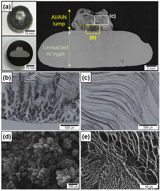
Figure 2.
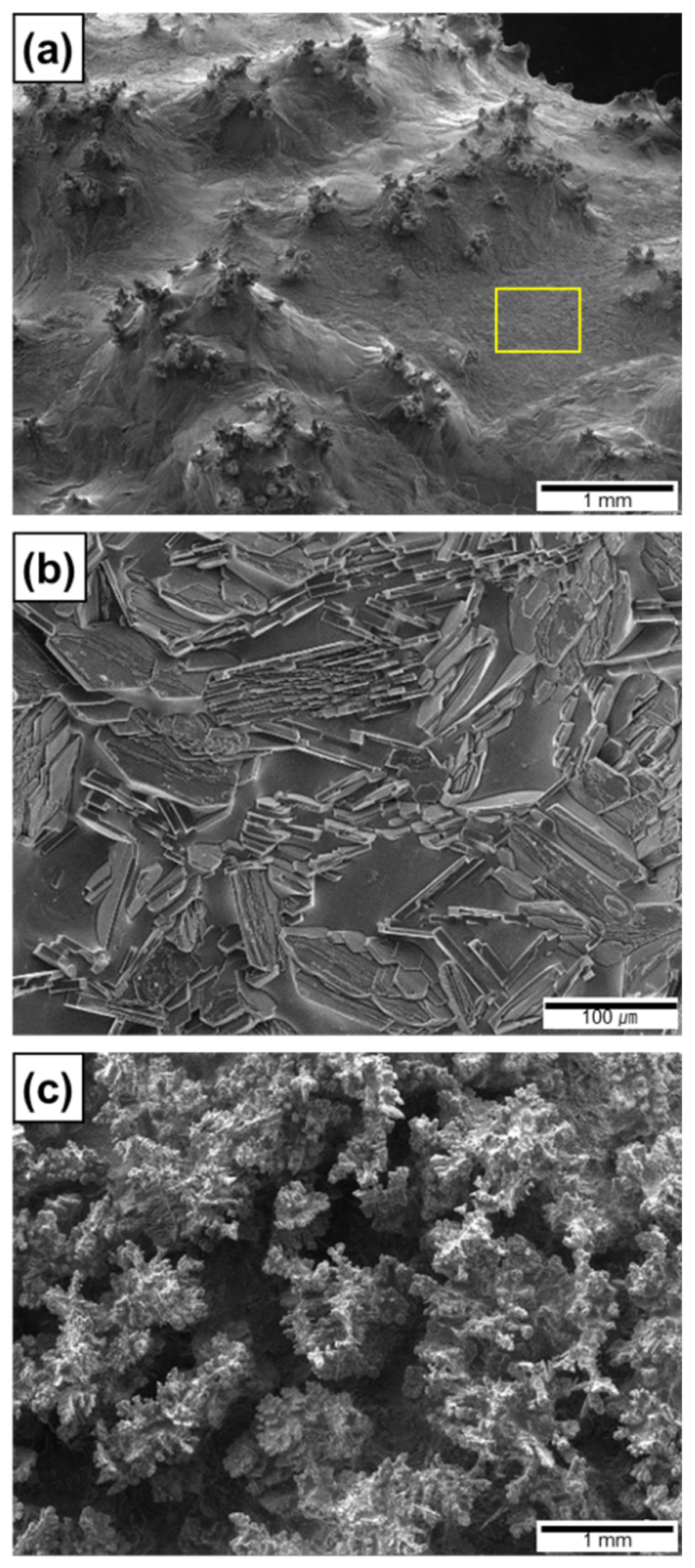
OM images of cross-section of (a) Al/AlN ingots after arc melting using fixed electrode. Magnified OM images of (b) lower and (c) upper sections of lump in (a). SEM images of in situ formed AlN (d) agglomerates and (e) lamellas on top surface.
The lump shows a three-dimensional interconnected structure of AlN (black portion shown in Figure 2b,c) and Al. The shapes of the AlN formed in situ at the lower (Figure 2b) and upper (Figure 2c) sections of the lump were different. To clearly show the AlN morphology, the top surface of the two lumps, formed at different nitridation time of 2 and 7 s, was observed by SEM. The AlN in the lower section comprised agglomerates of small particles (Figure 2d), whereas the AlN in the upper section comprised lamellar layers (Figure 2e). The WAlN was measured to be ~0.2 g, and the VAlN was calculated to be 30 ± 10 vol.% for the lump. The significant deviation in VAlN is attributed to the small volume and residual porosity of the lump, as well as the short reaction time.
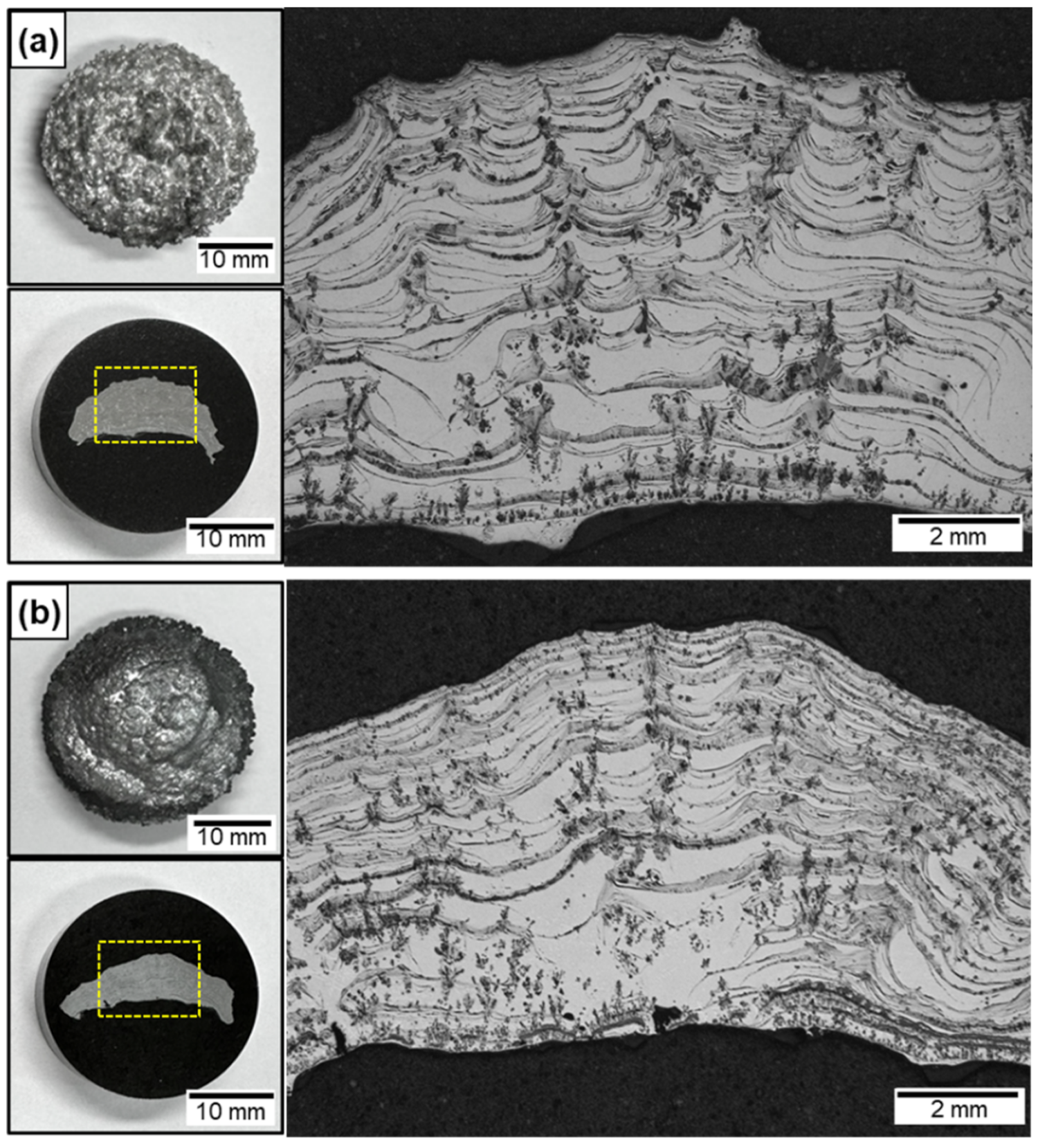
Figure 3a,b show the cross-sections of the Al/AlN and Al-12Si/AlN composite ingots after nitridation for 60 s with arc oscillation, as illustrated in Figure 1d. Compared with the lump formed locally at the top surface (Figure 2a), the in situ-formed AlN was homogeneously distributed in both the Al (Figure 3a) and Al-12Si (Figure 3b) matrix. Compared with the button shape of the ingot before nitridation, both the Al/AlN and Al-12Si/AlN composites exhibited a concave surface at the lower section of the ingots. This is due to the capillary flow of the Al melt through the in situ formed AlN structure, which will be discussed later. Despite the prolonged nitridation time from 10 to 60 s, the Al/AlN and Al-12Si/AlN composite ingots exhibited few pores in their cross-sections. Therefore, in this study, the thermal and mechanical properties of the composites were evaluated using specimens obtained from the middle of the composite ingots.
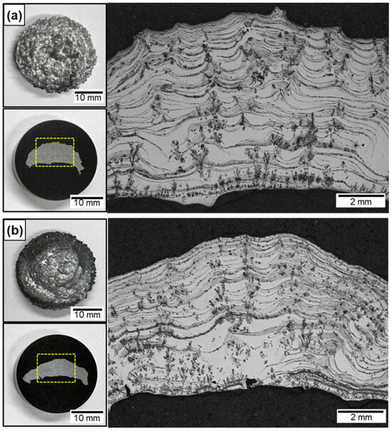
Figure 3.
OM images of (a) Al/AlN and (b) Al–12Si/AlN composite ingots arc melted for 60 s under arc oscillation. The yellow dashed boxes indicate the area where the cross-sections of the composites were observed.
Arrays of agglomerated AlN were observed in the lower section of both composite ingots (Figure 3a,b). However, agglomerates were observed in the middle, upper, and lower sections, which were not observed in the lump (Figure 2a–c). Both the Al/AlN and Al-12Si/AlN composites exhibited arrays of AlN lamellas, mainly in the middle and upper sections of the ingots. The interspacing of the lamellas was larger (~61 μm) than that of the lump (~23 μm in Figure 2c). The WAlN was ~1.0 g, and the VAlN was calculated to be 10 ± 1 vol.% in both the Al/AlN and Al-12Si/AlN composite ingots. The specific formation rate of AlN (WAlN divided by the reaction volume and nitridation time [13]) was calculated to be 3.28 × 10⁻¹ g/min·cm3 for the present study, which is 100–400 times higher than the nitridation rate of other in situ processes such as N2–gas bubbling (6.91 × 10⁻⁴ g/min·cm3 [38]) and solid-state processing (2.35 × 10⁻³ g/min·cm3 [17]). This indicates that APAVN accelerates the nitridation of Al.
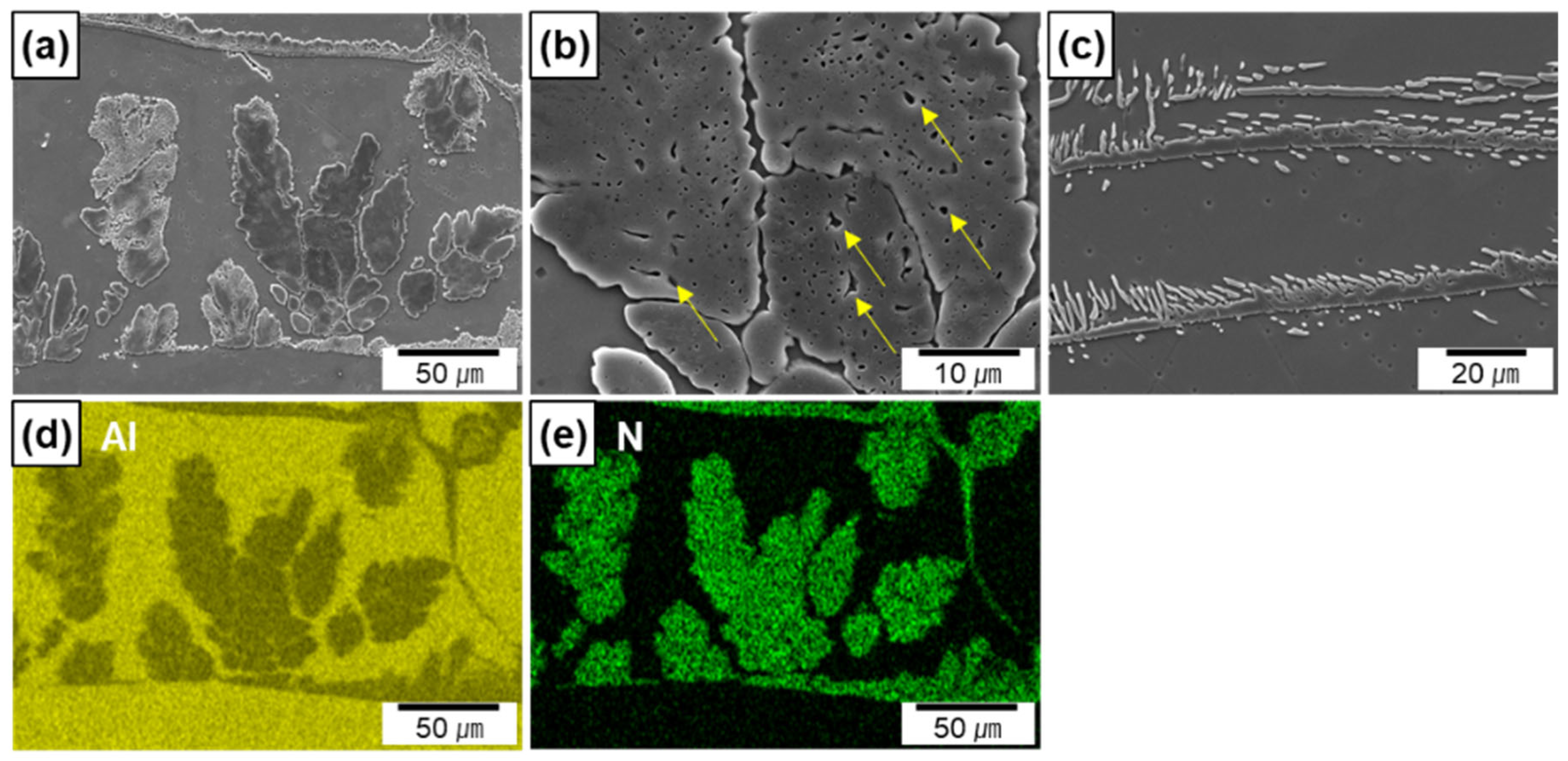
Figure 4a–c show the SEM micrographs of the Al/AlN composites at high magnification levels. Figure 4d,e show the EDS maps of Al and N taken from Figure 4a. The EDS maps clearly reveal the elemental distribution of N, which corresponds to the morphology of the in situ formed AlN. The widths of the AlN agglomerates ranged from 5 to 50 μm, and the interspacing between the agglomerates was between 10 and 110 μm. Residual Al was observed in the agglomerates (shown by yellow arrows in Figure 4b), thus indicating that a portion of the Al melt was entrapped during agglomerate formation. The thickness of the AlN lamella was 4 ± 1 μm (Figure 4c). Small spherical or rod-like AlN particles appeared around the lamellas. Based on previous findings, the particles in the micrograph are cross-sections of in situ-formed AlN rods or plates grown from AlN lamellas [13].

Figure 4.
SEM micrographs of in situ formed AlN in Al/AlN composites; (a,b) agglomerates, (c) lamellas, (d,e) EDS maps of Al and N from (a).
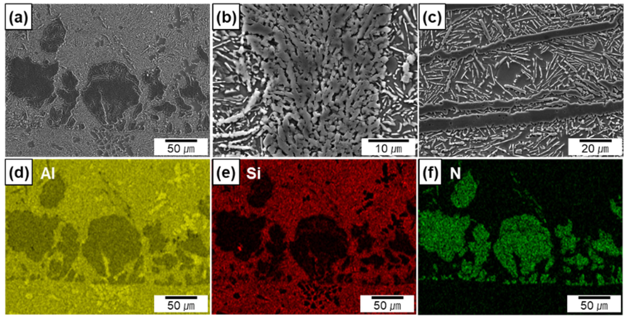
The electron micrographs (Figure 5a–c) and EDS maps (Figure 5d–f taken from Figure 5a) are shown for the Al-12Si/AlN composites. The EDS maps reveal that Si is mainly distributed in the metal matrix. Because of the near-eutectic composition of the metal matrix, the Si phase exhibited a flake shape in white contrast, whereas AlN was observed in gray contrast (Figure 5c). In the Si-containing composites, the sizes of the AlN agglomerates and the thicknesses of the AlN lamellas were similar to those of the Al/AlN composites (Figure 5b,c). However, compared to the agglomerates in the Al/AlN composite (Figure 4b), the residual Al in the agglomerates had co-continuous structure with AlN (Figure 5b) in the Al–12Si/AlN composite. The thickness of Al and AlN layers were measured to be 0.5 ± 0.2 and 1.3 ± 0.4 μm, respectively. The different morphology of the agglomerates may be associated with the reaction between Si and N during arc melting, which will be discussed later.
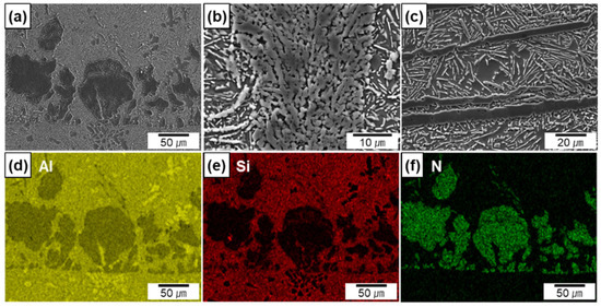
Figure 5.
SEM micrographs of in situ formed AlN in Al–12Si/AlN composites; (a,b) agglomerates, (c) lamellas, (d–f) EDS maps of Al, Si, and N.
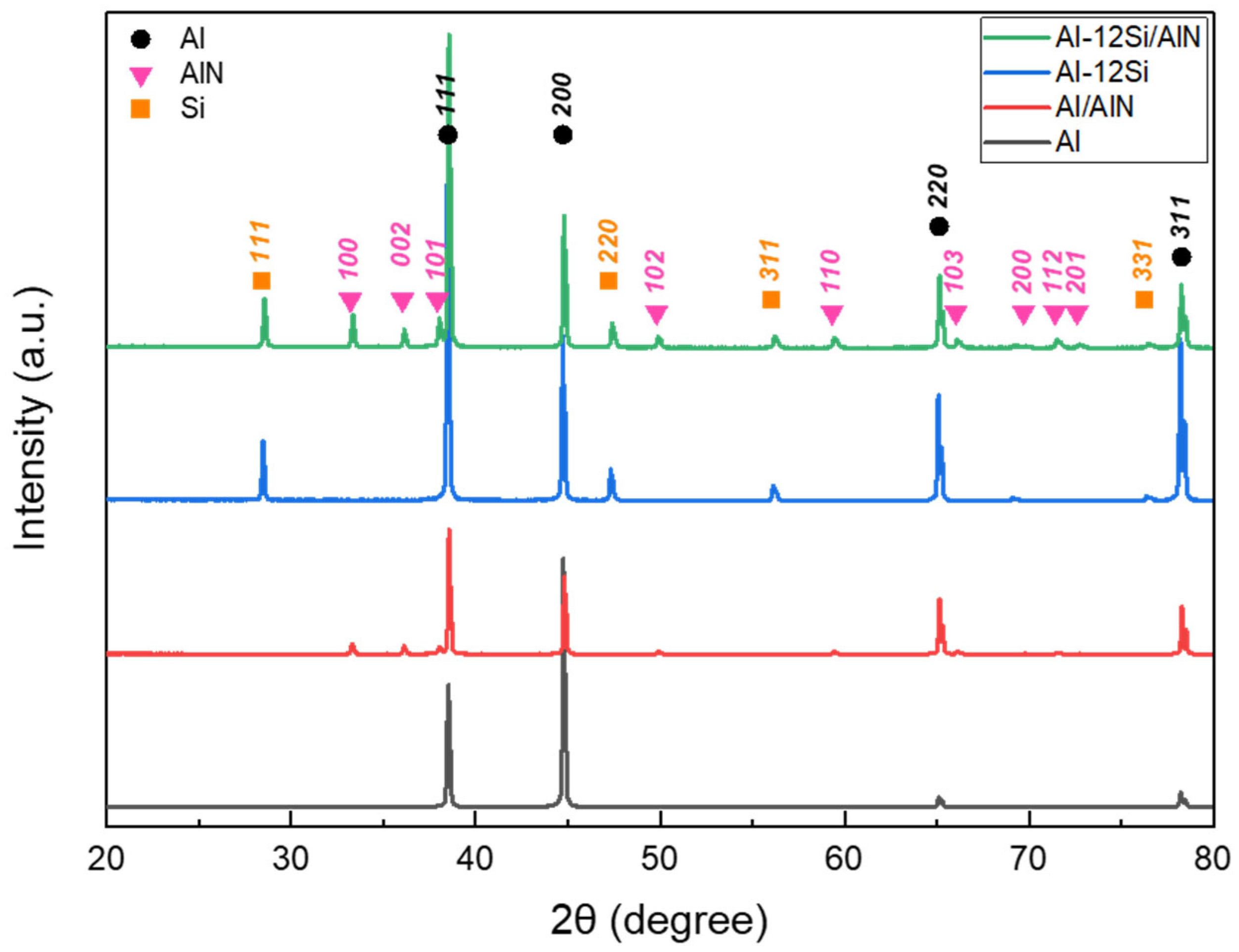
Figure 6 shows the XRD spectra of the cross-sections of the pure Al, Al–12Si alloy, Al/AlN, and Al–12Si/AlN composite ingots. As shown in Figure 4 and Figure 5, the Al/AlN and Al–12Si/AlN composites exhibited two- and three-phase microstructures of (Al and AlN) and (Al, Si, and AlN), respectively. These results indicate that no intermetallic compounds or oxides were formed during the reaction between the Al and Al–12Si alloys with N2 gas under an Ar + N2 atmosphere.
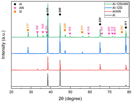
Figure 6.
XRD diffraction patterns of Al, Al–12Si alloys, and Al/AlN and Al–12Si/AlN composites.
3.2. Mechanical Properties
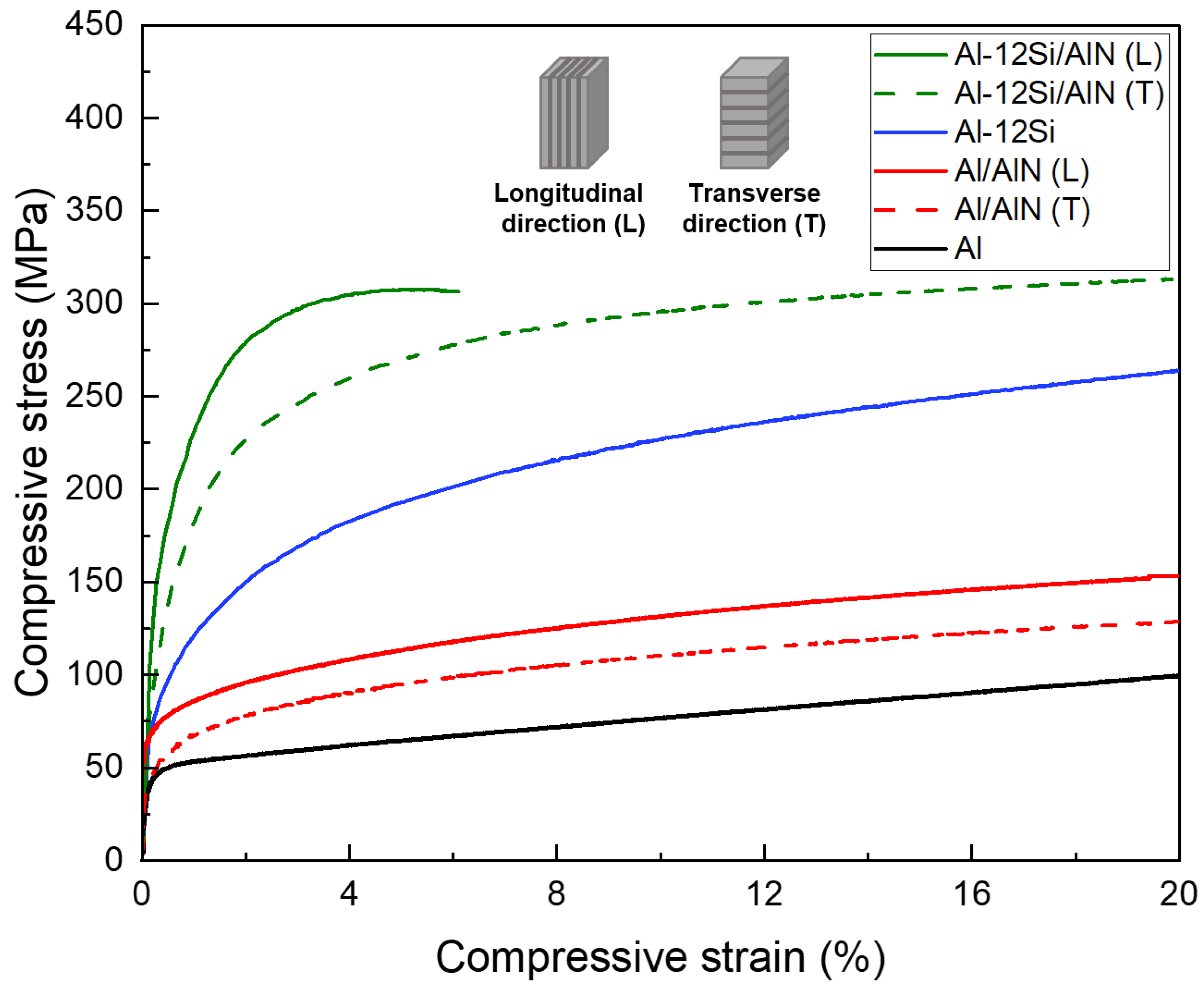
Figure 7 shows the compressive stress–strain curves of Al, Al–12Si alloy, Al/AlN, and Al–12Si/AlN composites. For the matrix materials, it was confirmed that the yield strength of Al-12Si alloy (94 MPa) was about two times higher than that of pure Al (44 MPa). This result reveals the strengthening of the Al matrix by the evenly dispersed Si phase (Figure 5a–f). To compare the effect of lamellar structure of AlN, the composite specimens were compressed along the longitudinal and transverse directions. Table 1 shows the yield compressive strength values of Al and Al-12Si matrix composites. The composites showed about 20–40% higher yield strength when compressed along the longitudinal direction due to the effective load transfer from the matrix to the AlN lamellas [39]. For both longitudinal and transverse directions, the Si-containing composites (195, 131 MPa) exhibit 2–3 times higher yield strength than the Al/AlN composites (70, 55 MPa). All the Al/AlN composites were compressed up to 20% without fracture, but the Al–12Si/AlN composite failed at a strain of ~6% (showing ultimate compressive strength of 308 MPa) when compressed along the longitudinal direction.
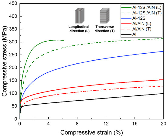
Figure 7.
Compressive stress–strain curves of Al, Al–12Si alloys, and Al/AlN and Al–12Si/AlN composites (L and T denote the longitudinal and transverse directions, respectively).

Table 1.
Yield strengths of Al and Al-12Si matrix composites with interconnected AlN aligned with longitudinal and transverse directions.
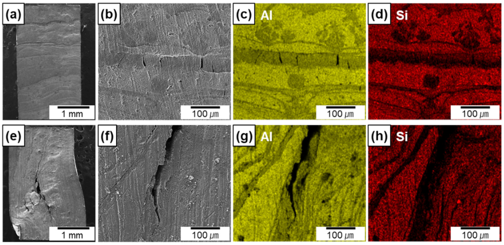
Figure 8a–h show the lateral surface of the Al-12Si/AlN composites compressed along the transverse (Figure 8a–d) and longitudinal (Figure 8e–h) directions with a compressive strain of ~6%. Both composites exhibited several cracks at the area where AlN lamellas were densely formed, which can be confirmed by the EDS maps (Figure 8c,d,g,h). For the composite compressed along the transverse direction, the formation of multiple cracks was confined between the Al-12Si metallic layers, which prevented interfacial debonding. However, for the composite compressed along the longitudinal direction, cracks can be propagated along the AlN lamellas which were aligned parallel to the loading direction. This led to a small amount of interfacial debonding and crack propagation from one AlN lamella to another, which resulted in the extensive deformation of metal matrix at local area and failure at the small strain of 6% (Figure 7).

Figure 8.
SEM images and EDS elemental maps of the lateral surface of the Al–12Si/AlN composites compressed along the transverse (a–d) and longitudinal (e–h) directions.
3.3. Thermal Properties
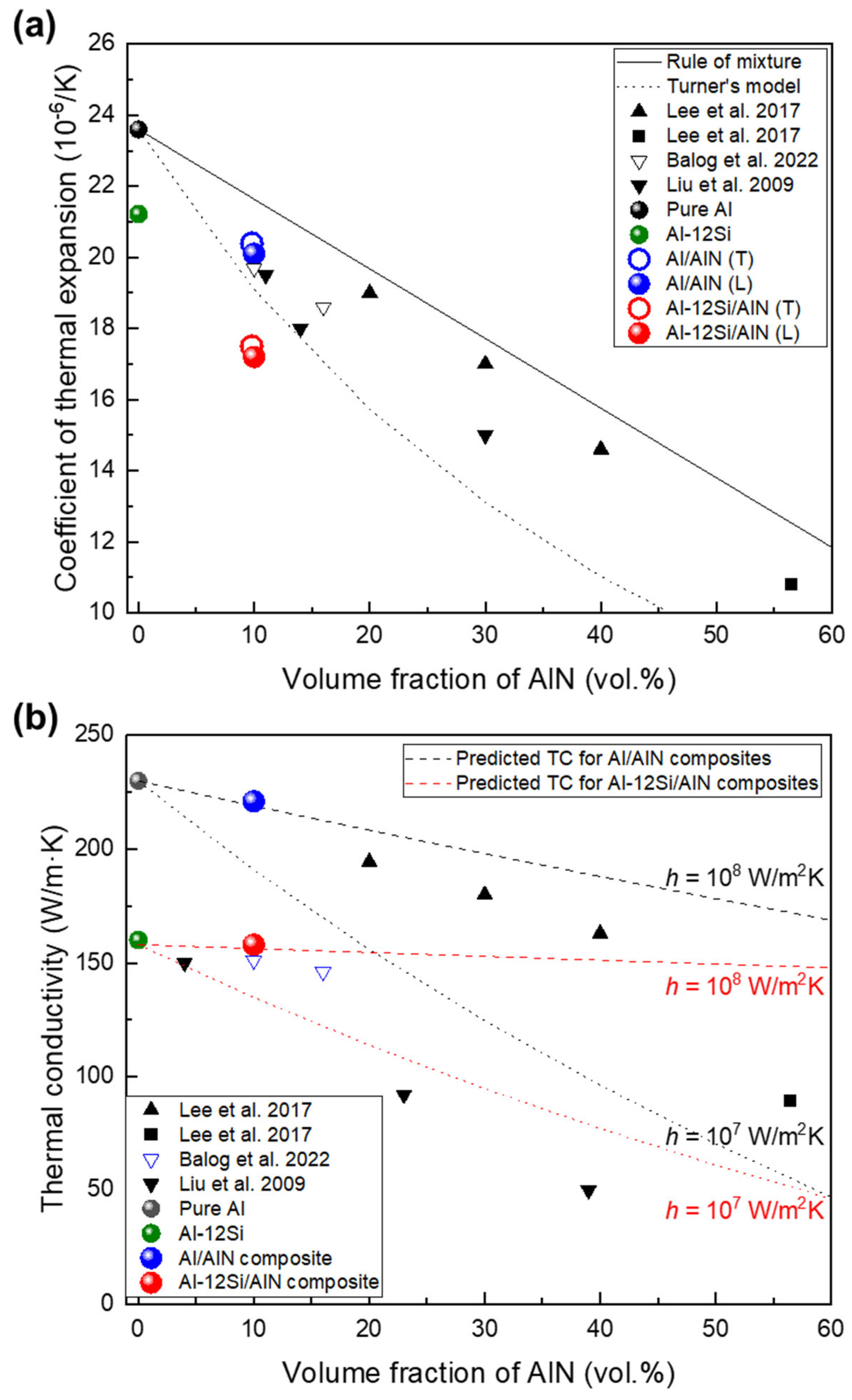
Figure 9a shows the CTE of the Al/AlN and Al–12Si/AlN composites and those of various Al/AlN composites [13,14,15,16]. Owing to the low CTE of AlN compared with that of Al (4.0 and 23.6 × 10⁻⁶/K, respectively), the CTE decreased as VAlN increased in the Al/AlN composites. The present and other Al/AlN composites exhibited CTE values lower than that based on the rule-of-mixture relationship, thus indicating strong interfacial cohesion between the matrix and reinforcement. In particular, the CTE of the present Al/AlN composite (20.1 × 10⁻⁶/K) was as low as that of nanocrystalline Al/AlN composites [15,16] and the CTE value was similar to that obtained using Turner’s model [40], which assumes an equilibrium of internal stress between the particles and matrix.
where α and B represent the CTE and bulk modulus, respectively; and subscripts c, m, and p refer to the composite, matrix, and particle (reinforcement), respectively. The correspondence between the CTE and that obtained Turner’s model indicates that the AlN reinforcements induced a large residual internal stress and constrained the linear expansion of the Al matrix [41], as similarly confirmed in Al/AlN nanocomposites [15,16] and co-continuous composites [14], which exhibit strong bonding between the matrix and reinforcement. Meanwhile, the Al–12Si/AlN composite exhibited a much lower CTE (17.0 × 10⁻⁶/K), which was about 30% lower than that of pure Al and 19% lower than that of Al–12Si alloy (21.2 × 10⁻⁶/K). This reduction in the CTE was significant, although the AlN fraction remained at ~10 vol.%. This result is attributed to the presence of a Si phase with a low CTE (2.2 × 10⁻⁶/K [14]) and its distribution in the matrix (eutectic Al–Si, as shown in Figure 5a–f), which contributed to greater restriction on the thermal expansion of the Al phase [33].
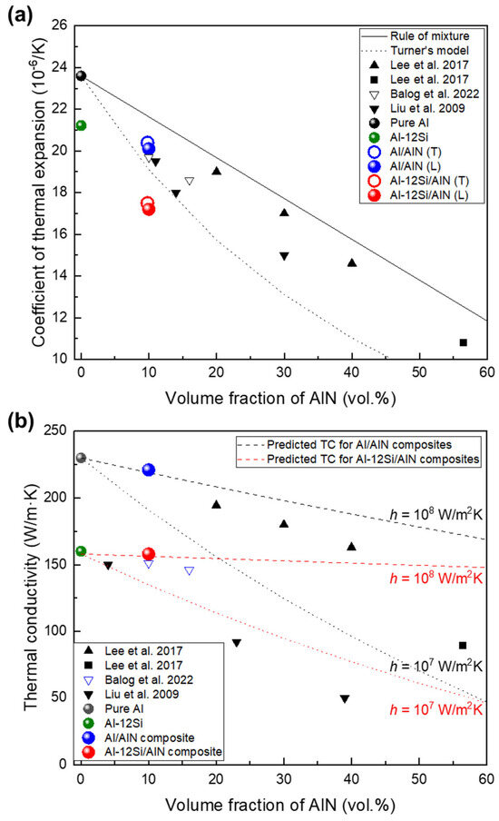
Figure 9.
(a) Coefficient of thermal expansion of present composites compared with those of various Al/AlN composites [13,14,15,16] and Turner’s model [40]; (b) thermal conductivity of composites compared with thermal conductivities predicted theoretically using H–J model [42].
Figure 9b shows the correlation between TC and VAlN in the present study and those of various Al/AlN composites. Compared with the TC values of pure Al (230 W/m·K) and the Al–12Si alloy (160 W/m·K), those of the Al/AlN and Al-12Si/AlN composites were 221 and 157 W/m·K, respectively. Therefore, the TC of present composites was slightly lower, even though 10 vol.% AlN was added into the Al and Al–12Si matrix. The Al/AlN composite showed a much higher TC than nanocrystalline Al/AlN composites with similar VAlN fabricated via extrusion (156 W/m·K [15]) or hot pressing (150 W/m·K [16]). This result is mainly attributed to the larger AlN size in the present composite (~5 μm, Figure 4a–c) than that in the nanocrystalline composites (diameter: ~50 nm [15,16]) owing to an increase in the particle size, which decreased the total interfacial area where thermal conduction is hindered.
Using the TC of each component (230 and 200 W/m·K for Al and AlN, respectively), the theoretically predicted TCs using the Hasselman–Johnson (H-J) model [42] with interfacial thermal conductance of 107 and 108 W/m2K are drawn as dotted lines in Figure 9b. The H–J model expresses the effective TC of a particulate composite as follows:
where K, r, and h represent the TC, particle radius, and interfacial thermal conductance, respectively. According to this model, the TC of a particulate composite increases with the particle size, as described previously. Furthermore, TC is affected significantly by the quality of the matrix/reinforcement interface because interfacial compounds or debonding degrade the thermal conductance at the interface.
The thermal conductance at an Al/AlN interface has been reported to be between ~1.9 × 10⁷ and 2.3 × 10⁸ W/m2K [13,43,44], which depends on the interfacial structure and processing condition. The TC of the Al/AlN composite (221 W/m·K) is comparable to that of a hypothetical particulate composite with 10 vol.% AlN (particle size of 5 μm) and an interfacial thermal conductance of 1.4 × 10⁸ W/m2K. This implies that the high TC of the Al/AlN composite can be attributed to the high interfacial thermal conductance, which results from the strong interfacial bonding afforded by APAVN. The estimated thermal conductance was higher than that of cold-rolled Al/AlN particulate composites (6.7 × 10⁷ W/m2K [13]). This comparison supports the H–J model in that the present composite with an interconnected structure exhibits less interfacial thermal resistance than the cold-rolled particulate composite because of the decrease in the interfacial area in the interconnected composites.
4. Discussion
The in situ formation of Al/AlN composites is demonstrated in this study using a simple arc-melting apparatus. The arc-melted Al/AlN composite exhibited a higher AlN formation rate (3.28 × 10⁻¹ g/min·cm3) than other in situ processes such as gas bubbling 6.91 × 10⁻⁴ g/min·cm3 [38]) and solid-state processing (2.35 × 10⁻³ g/min·cm3 [17]). Furthermore, the arc melting of Al under an Ar + N2 atmosphere resulted in the rapid formation of AMCs with 10 (in ingot) –30 (in lump) vol.% AlN within 1 min, which depended on the arc oscillation. In this study, the arc was intentionally shifted to increase the area of the gas–melt interface during APAVN. Using the oscillating electrode, nitridation occurred over the entire volume of the initial Al ingot, a high WAlN (1.0 g) was obtained, and bulk Al/AlN composite ingots (width ≥ 20 mm, thickness ≥ 5 mm) were successfully fabricated. The bottom surfaces of the composite ingots appeared to be concave, which indicates the upward infiltration of the Al melt during arc melting. Therefore, one can infer that the morphology of the in situ formed AlN structure, the VAlN, and the final shape of the composite ingots are closely related to the upward infiltration of liquid Al during arc melting.
4.1. Microstructural Evolution of Al/AlN Composite Ingots with Arc Oscillation
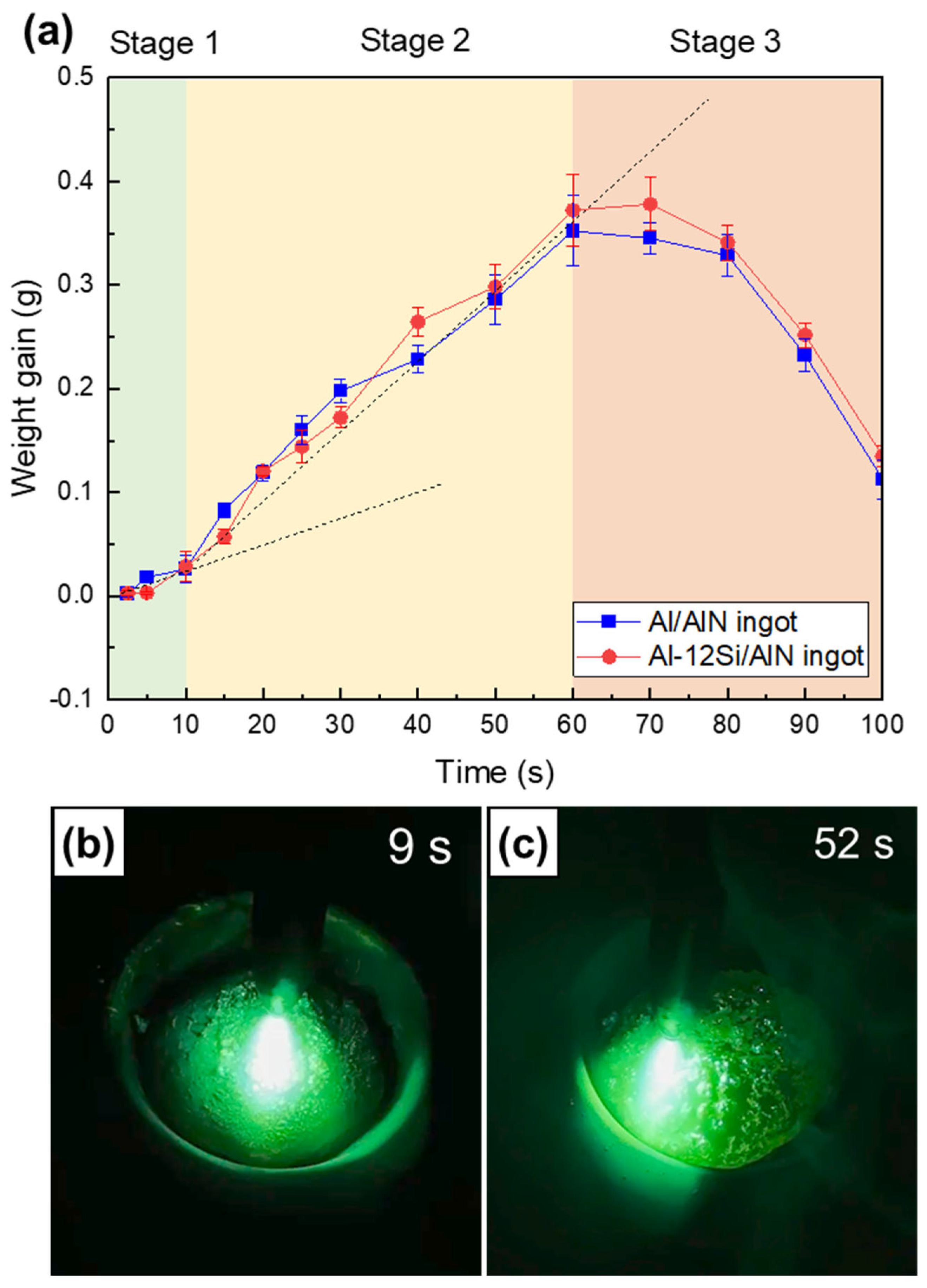
Figure 10a shows the measured weight gains (Wf − Wi,) of the Al/AlN and Al–12Si/AlN composite ingots, which were arc melted with arc oscillation. As a function of time, the weight change trend can be classified into Stages 1–3. The weight gain increased at a lower slope (Stage 1, t ≤ 10 s), peaked at a higher slope (Stage 2, 10 ≤ t ≤ 60 s), and then decreased significantly to a negative value (Stage 3, t ≥ 60 s). Figure 10b,c show images captured from the Supplementary Video S1, where an Al ingot was arc melted with arc oscillation under an Ar + N2 atmosphere. The top surfaces of the ingot at nitridation times of 9 s (Stage 1, Figure 10b), and 52 s (Stage 2, Figure 10c) are shown.

Figure 10.
(a) Measured weight gain curves of Al/AlN and Al–12Si/AlN composite ingots as a function of time. Captured images of APAVN at nitridation times of (b) 9 s (Stage 1) and (c) 52 s (Stage 2).
4.1.1. Stage 1: Incubation Period—Surface Nitridation
In Stage 1 (t ≤ 10 s), where the initial nitridation occurred, the in situ synthesis of AlN was localized at the top surface of the Al ingot. Nitridation at the surface is associated with the relatively low temperature of liquid Al. Because of the low solubility of N and the low growth rate of AlN at lower temperatures, the in situ formed AlNs exhibit the shape of an agglomerate (Figure 4a,b and Figure 5a,b) instead of a lamella [13]. The top surface of the Al ingot was dominated by AlN agglomerates (Figure 10b), and the Al melt was depleted. This resulted in nitridation confined to the surface and a lower formation rate of AlN (the slope in Figure 10a) in Stage 1.
4.1.2. Stage 2: Volume Nitridation
In Stage 2 (10 ≤ t ≤ 60 s), the weight gain curve (see Figure 10a) shows a slope that was ~2.5 times larger than that in Stage 1, thus indicating the change in the nitridation mechanism. When the nitridation time exceeded 10 s, the temperature of the Al melt increased due to exothermic heat released from the reaction between Al and N (Al + N = AlN, ΔH = −322 kJ/mol) as well as continuous arc discharge. The contact angle of an Al droplet on an AlN substrate has been reported to exceed 110° when the liquid temperature is lower than 800 °C [23], thus indicating the unsatisfactory wettability of AlN by liquid Al. However, the angle decreases to less than 40° if the liquid temperature exceeds 1100 °C [23,24,25]. At elevated temperatures, the wettability of AlN by liquid Al can be improved significantly, thus affecting nitridation [14]. The excellent wettability enables the Al melt to wet the in situ formed AlN agglomerates and rise spontaneously owing to the capillary effect, as shown in the lump (Figure 2a) and composite ingots (Figure 3a,b).
The upward flow of the Al melt is assisted by capillary pressure (ΔP), which can be calculated as follows:
where γ, θ, and r represent the surface tension, contact angle, and capillary radius, respectively. The surface tension of a liquid Al depends on the temperature, as indicated in the following equation: [γ = (868 − 0.152 × (T − Tm)) × 10−3 J/m2 [45]]. Using the interspacing of the AlN agglomerates, i.e., 10–110 μm, as the diameter of the capillary tube and assuming a contact angle of 40°, the capillary pressure was calculated to be in the range of −240 to −20 kPa at 1100 °C and −180 to −15 kPa at 2470 °C. This large negative pressure is similar to the external pressure required for the infiltration of liquid Al into a particulate ceramic preform [46,47]. The infiltration kinetics of the Al melt through the in situ-formed AlNs can be evaluated using the Washburn relation [47] as follows:
where h and μ are the infiltration height and liquid viscosity, respectively. Using the equation for the viscosity of an Al melt [μ = 0.1492 × exp(1984.5/T)/1000 N·s/m2], the infiltration height for 1 s is estimated to exceed 50 and 60 mm at 1100 °C and 2470 °C, respectively. These calculations rationalize the upward infiltration of the Al melt into the AlNs formed in situ on the top surface of the Al ingot within a few seconds during the arc melting process.
Figure 10c shows the top surface of the Al ingot during arc melting at a nitridation time of 52 s. As described above, the Al melt was spontaneously transported to the top surface and the fresh surface was exposed to the arc plasma. The previously formed AlNs on the top surface were wetted by the Al melt, as confirmed from the top surface of the composite ingot where nitridation was intentionally terminated at 30 s (Figure 11a). Owing to the elevated temperature of the Al ingot in Stage 2, the solubility of N and the growth rate of AlN in the Al melt increased significantly. These changes resulted in the formation of AlN lamellas, plates, and rods (Figure 4c) [13]. The synthesis of these AlN particles can be observed on the newly formed surface (yellow square in Figure 11a), where AlN lamellas and plates were grown (Figure 11b). These AlNs can serve as new capillary tubes for the upward infiltration of the Al melt, thus resulting in the formation of AlN lamellas (Figure 4c and Figure 5c) in the Al matrix. Thus, the infiltration and nitridation of the Al melt can be repeated until arc melting is terminated, which results in (1) the synthesis of numerous AlN lamellas in the entire volume of the Al ingot and (2) a higher formation rate of AlN in Stage 2 than that in Stage 1.

Figure 11.
Morphologies of AlN on top surface of Al/AlN ingots showing (a) wetting of AlN agglomerates, (b) formation of AlN lamellas, and (c) formation of interconnected pores due to excessive arc melting.
4.1.3. Stage 3: Evaporation Period
In Stage 3 (t ≥ 60 s), the weight of the Al/AlN ingot decreased significantly (Figure 10a). This weight loss is attributed to the evaporation of the Al melt in the ingot, which indicates that the liquid temperature reached the boiling point of Al. The evaporation under prolonged arc melting can be utilized to prepare Al and AlN ultrafine powders [19,48]. However, excessive melting resulted in the formation of interconnected pores in the resulting composite ingot. Figure 11c shows the top surface of the ingot nitrided for 100 s. Dendritic growth of AlNs was observed; however, a significant amount of the Al matrix was absent, which resulted in composites with inferior mechanical and thermal properties. Thus, the excessive arc melting of Al ingots under Ar and N2 atmospheres should be avoided to obtain composites with lower porosity.
4.2. Mechanism of In Situ Synthesis of Al/AlN Composite Ingots
Figure 12 shows a schematic illustration of the nitridation of an Al ingot via arc melting. An Al ingot was placed on a water-cooled Cu hearth, and melted under arc oscillation. Initially, when the temperature of the Al melt was relatively low (Stage 1), AlNs in the shape of an agglomerate were mainly formed on the top surface (Figure 12a). As the nitridation proceeded (Stage 2), the liquid temperature increased, and the Al melt under the surface was transported upward through the AlN structure formed in situ owing to capillary pressure (Figure 12b,c). This resulted in the formation of AlN lamellas on the newly formed liquid surfaces. Owing to the upward infiltration of the Al melt, the area of Ohmic contact between the Al ingot and Cu hearth decreased gradually, which resulted in composite ingots with a concave surface after the nitridation terminated (Figure 12d). In Stage 2, the liquid temperature was uneven in the ingot because the Al melt was locally heated by the arc, which resulted in the intermittent cooling of the Al ingot behind the arc plasma. As the liquid temperature reduced locally, the solubility of N decreased, and AlN agglomerates formed in the middle and upper sections of the composite ingot, as shown in Figure 3. At the end of Stage 2, the liquid temperature reached the boiling point of Al, and the Al melt evaporated, which resulted in the formation of interconnected pores in the ingot. The abovementioned evaporation was not observed when the pure Al ingot was arc melted under an inert Ar atmosphere. An extremely high temperature can be achieved by decreasing the area of the Ohmic contact (Figure 12d), which delays heat transfer from the Al ingot to the Cu hearth.
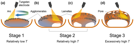
Figure 12.
Schematic diagram showing nitridation mechanism. (a) Formation of AlN agglomerates on the top surface in stage 1; (b,c) formation of AlN lamellas on the top surface where Al melt is transported upward. (d) formation of an Al/AlN ingot with concave surface at the bottom surface and pores at the top surface.
In this study, Al–12Si ingots were nitrided via arc melting; however, this did not significantly alter the VAlN (~10 vol.%) and the final shape of the resulting composite ingots. In the Al–12Si/AlN ingot, the AlN agglomerates showed co-continuous structure with layer thicknesses of 0.5 and 1.5 μm for Al and AlN, respectively (Figure 5b). This morphology may be related to the formation of an intermediate Si3N4 phase. The formation of AlN from liquid Al can be catalyzed by the addition of Si because of the nitridation of Si (3Si + 4N = Si3N4) and the displacement reaction of Si3N4 to AlN (Si3N4 + 4Al = 4AlN + 3Si) [49]. In particular, the arc plasma-induced displacement reaction can result in the formation of co-continuous nitride structures [14], whose morphology is similar to that of the AlN agglomerates shown in Figure 5b. However, evidence of the catalytic effect of Si was not confirmed in this study because the diffraction peaks of Si3N4 phase was not detected in XRD spectrum (Figure 6) and any segregation of Si was not observed in the SEM micrographs (Figure 5a–c). The effect of Si addition on the nitridation mechanism of Al during APAVN is currently being investigated.
4.3. Thermal Properties of In Situ Formed Al/AlN Composites
During arc melting, the in situ-formed AlN was spontaneously wetted and infiltrated with liquid Al owing to the improved wettability by the arc plasma-induced high temperature. The in situ synthesis of AlN resulted in strong interfacial bonding between AlN and Al and contributed to the high interfacial conductance in the resulting composites, as confirmed in Figure 9b. The APAVN resulted in the formation of AlN in the shape of agglomerates and lamellas, which resulted in an interconnected structure of Al and AlN in the composite ingots. The three-dimensional architecture can significantly limit the thermal expansion of the composite, thus causing a further reduction in the CTE of the Al/AlN and Al-12Si/AlN composites (Figure 9a).
Figure 13 shows the specific TC of the Al/AlN and Al–12Si/AlN composites compared with those of various pure metals, Al/AlN composites, and semiconducting materials as a function of the CTE. To design a novel heat sink material, the density must be considered to reduce the weight of the final products. Compared with high-density transition metals and low-TC Al/AlN nanocomposites [15,16], the Al/AlN and Al–12Si/AlN composites showed higher specific TCs. In particular, the CTE of the Al–12Si/AlN composite was much lower than that of pure Al and similar to that of pure Cu, resulting in higher K/ρα value of ~4 × 10³. Thus, interconnected AlN-reinforced Al-12Si matrix composites afford a unique combination of high specific TC and low CTE.
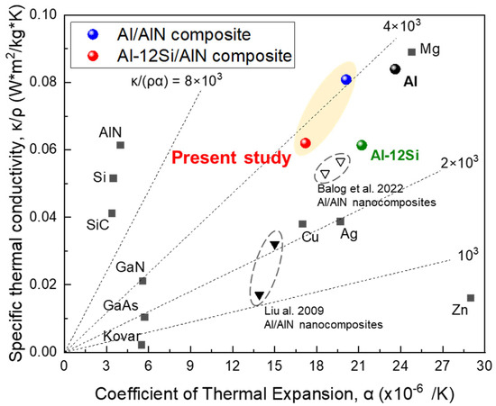
Figure 13.
Correlation between specific TC and CTE of present Al/AlN and Al–12Si/AlN composites compared with those of other in situ Al/AlN nanocomposites [15,16], transition metals, and semiconducting materials.
For heat sink applications, the CTE of the present composites must be decreased further to reduce the CTE mismatch with heat source materials such as GaN (5.5 × 10⁻⁶/K) or GaAs (6.0 × 10⁻⁶/K), which are used for high-power semiconductor devices [4]. Thus, the proportions of AlN and Si in the AMC ingot should be increased, and its interconnected structure should be customized to effectively constrain the expansion of the Al phase. Despite the small reaction volume and WAlN, the lump (Figure 2) showed a dense AlN structure and a high VAlN of ~30 vol.%. This implies that the arc-melting conditions must be optimized to obtain Al(-Si)/AlN composites with excellent thermal properties.
Compared to the initial shape of Al alloy ingots before nitridation (Figure 1b), both Al/AlN and Al-12Si/AlN composite ingots exhibited a concave surface at their low section (Figure 3a,b). For heat sink applications, the composite ingots will need to be shaped by thermomechanical processing. Cold-rolling of the Al/AlN composite ingots was found to be feasible [13], but the severe plastic deformation of the Al-12Si/AlN composites at room temperature seems to be difficult due to their high strength and low ductility (Figure 7). One possible way will be forging of the composite at elevated temperature, which is currently under investigation.
5. Conclusions
In this study, we demonstrated the in situ synthesis of AMCs reinforced with interconnected AlN via the APAVN of Al alloys with N2 gas. AMCs with 10 vol.% AlN were synthesized with a high AlN formation rate of 3.28 × 10⁻¹ g/min·cm3. The homogeneous dispersion of AlN in the matrix was achieved via arc oscillation in circular motion, which increases the area of the N2 gas–Al melt interface and delays the elevation of the interface. The microstructural evolution of the Al/AlN ingots during APAVN was proposed to explain the volume nitridation mechanism of the Al ingot. The rapid formation of AlN was significantly affected by the liquid temperature, which influenced the wetting and infiltration behaviors of the Al melt. The resulting composites exhibited improved compressive properties (from 70 to 195 MPa) when 12 at.% Si was added to the matrix. The Al-12Si/AlN composites displayed higher specific TC than Al/AlN nanocomposites with similar AlN fraction. In particular, the CTE of the arc-melted Al/AlN composite was further reduced in the Al-12Si/AlN composites (from 20.1 to 17.0 × 10⁻⁶/K) where both interconnected AlN architecture and eutectic Si microstructure induced significant constraints on the thermal expansion of the Al phase. These findings would provide guidelines for designing novel AMCs reinforced with interconnected AlN architecture via APAVN for heat sink applications.
Supplementary Materials
The following supporting information can be downloaded at: https://www.mdpi.com/article/10.3390/met13121967/s1, Video S1.
Author Contributions
Conceptualization, J.I.L.; Methodology, S.J.; Validation, T.K.; Investigation, S.J. and J.I.L.; Resources, J.I.L.; Writing—original draft, S.J. and T.K.; Writing—review and editing, J.I.L.; Visualization, T.K.; Supervision, J.I.L. All authors have read and agreed to the published version of the manuscript.
Funding
This study was supported by the National Research Foundation of Korea (NRF) funded by the Korea government (MSIT) (No. 2020R1G1A1101423, 2021R1C1C1012310), and 2023 BK21 FOUR Graduate School Innovation Support funded by Pusan National University (PNU-Fellowship program).
Data Availability Statement
Data are contained within the article and Supplementary Materials.
Conflicts of Interest
The authors declare no conflict of interest.
References
- Zweben, C. Metal-Matrix Composites for Electronic Packaging. Jom 1992, 44, 15–23. [Google Scholar] [CrossRef]
- Han, X.H.; Wang, Q.; Park, Y.G.; T’Joen, C.; Sommers, A.; Jacobi, A. A Review of Metal Foam and Metal Matrix Composites for Heat Exchangers and Heat Sinks. Heat Transf. Eng. 2012, 33, 991–1009. [Google Scholar] [CrossRef]
- Zhang, A.; Li, Y. Thermal Conductivity of Aluminum Alloys—A Review. Materials 2023, 16, 2972. [Google Scholar] [CrossRef] [PubMed]
- Pengelly, R.S.; Wood, S.M.; Milligan, J.W.; Sheppard, S.T.; Pribble, W.L. A Review of GaN on SiC High Electron-Mobility Power Transistors and MMICs. IEEE Trans. Microw. Theory Tech. 2012, 60, 1764–1783. [Google Scholar] [CrossRef]
- Lee, S.; Son, S.H.; Kim, J.; Yesuraj, J.; Kim, K.; Rhi, S.H. Heat conduction and thermal expansion of copper–graphite composite as a heat sink. Int. J. Energy Res. 2022, 46, 10907–10918. [Google Scholar] [CrossRef]
- Tayebi, M.; Jozdani, M.; Mirhadi, M. Thermal expansion behavior of Al–B4C composites by powder metallurgy. J. Alloys Compd. 2019, 809, 151753. [Google Scholar] [CrossRef]
- Lee, M.; Choi, Y.; Sugio, K.; Matsugi, K.; Sasaki, G. Effect of aluminum carbide on thermal conductivity of the unidirectional CF/Al composites fabricated by low pressure infiltration process. Compos. Sci. Technol. 2014, 97, 1–5. [Google Scholar] [CrossRef]
- Nyanor, P.; El-Kady, O.; Yehia, H.M.; Hamada, A.S.; Hassan, M.A. Effect of bimodal-sized hybrid TiC–CNT reinforcement on the mechanical properties and coefficient of thermal expansion of aluminium matrix composites. Met. Mater. Int. 2021, 27, 753–766. [Google Scholar] [CrossRef]
- Schöbel, M.; Altendorfer, W.; Degischer, H.-P.; Vaucher, S.; Buslaps, T.; Di Michiel, M.; Hofmann, M. Internal stresses and voids in SiC particle reinforced aluminum composites for heat sink applications. Compos. Sci. Technol. 2011, 71, 724–733. [Google Scholar] [CrossRef]
- Kumar, C.R.; Malarvannan, R.R.R.; JaiGanesh, V. Role of SiC on mechanical, tribological and thermal expansion characteristics of B4C/talc-reinforced Al-6061 hybrid composite. Silicon 2020, 12, 1491–1500. [Google Scholar] [CrossRef]
- Kim, D.-Y.; Cha, P.-R.; Nam, H.-S.; Choi, H.-J.; Lee, K.-B. Effect of material and process variables on characteristics of nitridation-induced self-formed aluminum matrix composites—Part 1: Effect of reinforcement volume fraction, size, and processing temperatures. Materials 2020, 13, 1309. [Google Scholar] [CrossRef] [PubMed]
- Baig, M.M.A.; Hassan, S.F.; Saheb, N.; Patel, F. Metal Matrix Composite in Heat Sink Application: Reinforcement, Processing, and Properties. Materials 2021, 14, 6257. [Google Scholar] [CrossRef]
- Lee, J.I.; Park, E.S. In situ synthesis of cold-rollable aluminum–aluminum nitride composites via arc plasma-induced accelerated volume nitridation. J. Mater. Res. 2017, 32, 217–226. [Google Scholar] [CrossRef]
- Lee, J.I.; Park, E.S. In-Situ synthesis of co-continuous aluminum-aluminum nitride composites by arc plasma induced accelerated displacement reaction. J. Alloys Compd. 2017, 729, 171–179. [Google Scholar] [CrossRef]
- Balog, M.; Krizik, P.; Dvorak, J.; Bajana, O.; Krajcovic, J.; Drienovsky, M. Industrially fabricated in-situ Al-AlN metal matrix composites (part B): The mechanical, creep, and thermal properties. J. Alloys Compd. 2022, 909, 164720. [Google Scholar] [CrossRef]
- Liu, Y.; Cong, H.; Cheng, H. Thermal properties of nanocrystalline Al composites reinforced by AlN nanoparticles. J. Mater. Res. 2009, 24, 24–31. [Google Scholar] [CrossRef]
- Balog, M.; Krizik, P.; Svec, P., Jr.; Orovcik, L. Industrially fabricated in-situ Al-AlN metal matrix composites (part A): Processing, thermal stability, and microstructure. J. Alloys Compd. 2021, 883, 160858. [Google Scholar] [CrossRef]
- Balog, M.; Yu, P.; Qian, M.; Behulova, M.; Sr, P.S.; Cicka, R. Nanoscaled Al–AlN composites consolidated by equal channel angular pressing (ECAP) of partially in situ nitrided Al powder. Mater. Sci. Eng. A 2013, 562, 190–195. [Google Scholar] [CrossRef]
- Liu, Y.; Cong, H.; Wang, W.; Sun, C.; Cheng, H. AlN nanoparticle-reinforced nanocrystalline Al matrix composites: Fabrication and mechanical properties. Mater. Sci. Eng. A 2009, 505, 151–156. [Google Scholar] [CrossRef]
- Kim, J.; Park, J.; Shim, C.-H.; Ahn, J.-P.; Choi, H.; Lee, K.-B. Preparation of Al/AlN composites by in-situ reaction in the nitridation-induced self-forming process. J. Compos. Mater. 2022, 56, 3653–3658. [Google Scholar] [CrossRef]
- Mohanavel, V.; Rajan, K.; Ravichandran, M. Synthesis, characterization and properties of stir cast AA6351-aluminium nitride (AlN) composites. J. Mater. Res. 2016, 31, 3824–3831. [Google Scholar] [CrossRef]
- Kida, M.; Bahraini, M.; Molina, J.; Weber, L.; Mortensen, A. High-temperature wettability of aluminum nitride during liquid metal infiltration. Mater. Sci. Eng. A 2008, 495, 197–202. [Google Scholar] [CrossRef]
- Ho, H.N.; Wu, S.T. The wettability of molten aluminum on sintered aluminum nitride substrate. Mater. Sci. Eng. A 1998, 248, 120–124. [Google Scholar] [CrossRef]
- Toy, C.; Scott, W. Wetting and spreading of molten aluminium against AlN surfaces. J. Mater. Sci. 1997, 32, 3243–3248. [Google Scholar] [CrossRef]
- Nicholas, M.; Mortimer, D.; Jones, L.; Crispin, R. Some observations on the wetting and bonding of nitride ceramics. J. Mater. Sci. 1990, 25, 2679–2689. [Google Scholar] [CrossRef]
- Gao, T.; Li, Z.; Hu, K.; Bian, Y.; Liu, X. Assessment of AlN/Mg–8Al composites reinforced with in situ and/or ex situ AlN particles. Materials 2020, 14, 52. [Google Scholar] [CrossRef] [PubMed]
- Scholz, H.; Greil, P. Nitridation reactions of molten Al-(Mg, Si) alloys. J. Mater. Sci. 1991, 26, 669–677. [Google Scholar] [CrossRef]
- Kumari, S.S.; Pillai, U.; Pai, B. Synthesis and characterization of in situ Al–AlN composite by nitrogen gas bubbling method. J. Alloys Compd. 2011, 509, 2503–2509. [Google Scholar] [CrossRef]
- Thibault, S.; Hug, E. Corrosion and wear mechanisms of aluminum alloys surface reinforced by multicharged N-implantation. Appl. Surf. Sci. 2014, 310, 311–316. [Google Scholar] [CrossRef]
- Ebisawa, T.; Saikudo, R. Formation of aluminum nitride on aluminum surfaces by ECR nitrogen plasmas. Surf. Coat. Technol. 1996, 86, 622–627. [Google Scholar] [CrossRef]
- Li, X.; Xin, W.; Zheng, X.; Ren, Z.A.; Sun, D.; Lu, W. Microstructural characterization and formation mechanism of nitrided layers on aluminum substrates by thermal plasma nitriding. Metals 2019, 9, 523. [Google Scholar] [CrossRef]
- Nithesh, K.; Gowrishankar, M.; Nayak, R.; Sharma, S. Effect of light weight reinforcement and heat treatment process parameters on morphological and wear aspects of hypoeutectic Al-Si based composites-a critical review. J. Mater. Res. Technol. 2021, 15, 4272–4292. [Google Scholar] [CrossRef]
- Ma, P.; Jia, Y.; Prashanth, K.G.; Yu, Z.; Li, C.; Zhao, J.; Yang, S.; Huang, L. Effect of Si content on the microstructure and properties of Al–Si alloys fabricated using hot extrusion. J. Mater. Res. 2017, 32, 2210–2217. [Google Scholar] [CrossRef]
- Chen, J.; Hung, H.; Wang, C.; Tang, N. Thermal and electrical conductivity in Al–Si/Cu/Fe/Mg binary and ternary Al alloys. J. Mater. Sci. 2015, 50, 5630–5639. [Google Scholar] [CrossRef]
- Zhang, X.; Zhou, Y.; Zhong, G.; Zhang, J.; Chen, Y.; Jie, W.; Schumacher, P.; Li, J. Effects of Si and Sr elements on solidification microstructure and thermal conductivity of Al–Si-based alloys. J. Mater. Sci. 2022, 57, 6428–6444. [Google Scholar] [CrossRef] [PubMed]
- Zhang, A.; Li, Y. Effect of alloying elements on thermal conductivity of aluminum. J. Mater. Res. 2023, 38, 2049–2058. [Google Scholar] [CrossRef]
- Yokoyama, Y.; Fukaura, K.; Inoue, A. Cast structure and mechanical properties of Zr–Cu–Ni–Al bulk glassy alloys. Intermetallics 2002, 10, 1113–1124. [Google Scholar] [CrossRef]
- Zheng, Q.; Reddy, R. Mechanism of in situ formation of AlN in Al melt using nitrogen gas. J. Mater. Sci. 2004, 39, 141–149. [Google Scholar] [CrossRef]
- Shaga, A.; Shen, P.; Sun, C.; Jiang, Q. Lamellar-interpenetrated Al–Si–Mg/SiC composites fabricated by freeze casting and pressureless infiltration. Mater. Sci. Eng. A 2015, 630, 78–84. [Google Scholar] [CrossRef]
- Turner, P.S. The problem of thermal-expansion stresses in reinforced plastics. J. Res. Natl. Bur. Stand. 1946, 37, 239–250. [Google Scholar] [CrossRef]
- Huber, T.; Degischer, H.-P.; Lefranc, G.; Schmitt, T. Thermal expansion studies on aluminium-matrix composites with different reinforcement architecture of SiC particles. Compos. Sci. Technol. 2006, 66, 2206–2217. [Google Scholar] [CrossRef]
- Hasselman, D.; Johnson, L.F. Effective thermal conductivity of composites with interfacial thermal barrier resistance. J. Compos. Mater. 1987, 21, 508–515. [Google Scholar] [CrossRef]
- Mizuuchi, K.; Inoue, K.; Agari, Y.; Nagaoka, T.; Sugioka, M.; Tanaka, M.; Takeuchi, T.; Tani, J.-I.; Kawahara, M.; Makino, Y. Processing and thermal properties of Al/AlN composites in continuous solid–liquid co-existent state by spark plasma sintering. Compos. B Eng. 2012, 43, 1557–1563. [Google Scholar] [CrossRef]
- Stevens, R.J.; Smith, A.N.; Norris, P.M. Measurement of thermal boundary conductance of a series of metal-dielectric interfaces by the transient thermoreflectance technique. J. Heat Transf. 2005, 127, 315–322. [Google Scholar] [CrossRef]
- Hatch, J.E. Aluminum: Properties and Physical Metallurgy; American Society for Metals: Detroit, MA, USA, 1984; pp. 1–24. [Google Scholar]
- Garcia-Cordovilla, C.; Louis, E.; Narciso, J. Pressure infiltration of packed ceramic particulates by liquid metals. Acta Mater. 1999, 47, 4461–4479. [Google Scholar] [CrossRef]
- Liu, B.; Liu, X.; Liu, M.; Zhao, Z. Infiltration mechanism in SiCp/aluminum-matrix composite prepared by nonpressure. Mater. Manuf. Process. 2011, 26, 1339–1345. [Google Scholar] [CrossRef]
- Ageorges, H.; Megy, S.; Chang, K.; Baronnet, J.-M.; Williams, J.; Chapman, C. Synthesis of aluminum nitride in transferred arc plasma furnaces. Plasma Chem. Plasma Process. 1993, 13, 613–632. [Google Scholar] [CrossRef]
- Li, X.; Xin, W.; Wang, Y.; Wang, W. Aluminium nitride layers prepared by nitrogen arc discharge on Al-Si alloy substrate. J. Mater. Process Technol. 2021, 288, 116847. [Google Scholar] [CrossRef]


Disclaimer/Publisher’s Note: The statements, opinions and data contained in all publications are solely those of the individual author(s) and contributor(s) and not of MDPI and/or the editor(s). MDPI and/or the editor(s) disclaim responsibility for any injury to people or property resulting from any ideas, methods, instructions or products referred to in the content. |
© 2023 by the authors. Licensee MDPI, Basel, Switzerland. This article is an open access article distributed under the terms and conditions of the Creative Commons Attribution (CC BY) license (https://creativecommons.org/licenses/by/4.0/).