

Wear and Corrosion Resistance of CrYN Coating in Artificial Seawater
Abstract
:1. Introduction
2. Materials and Methods
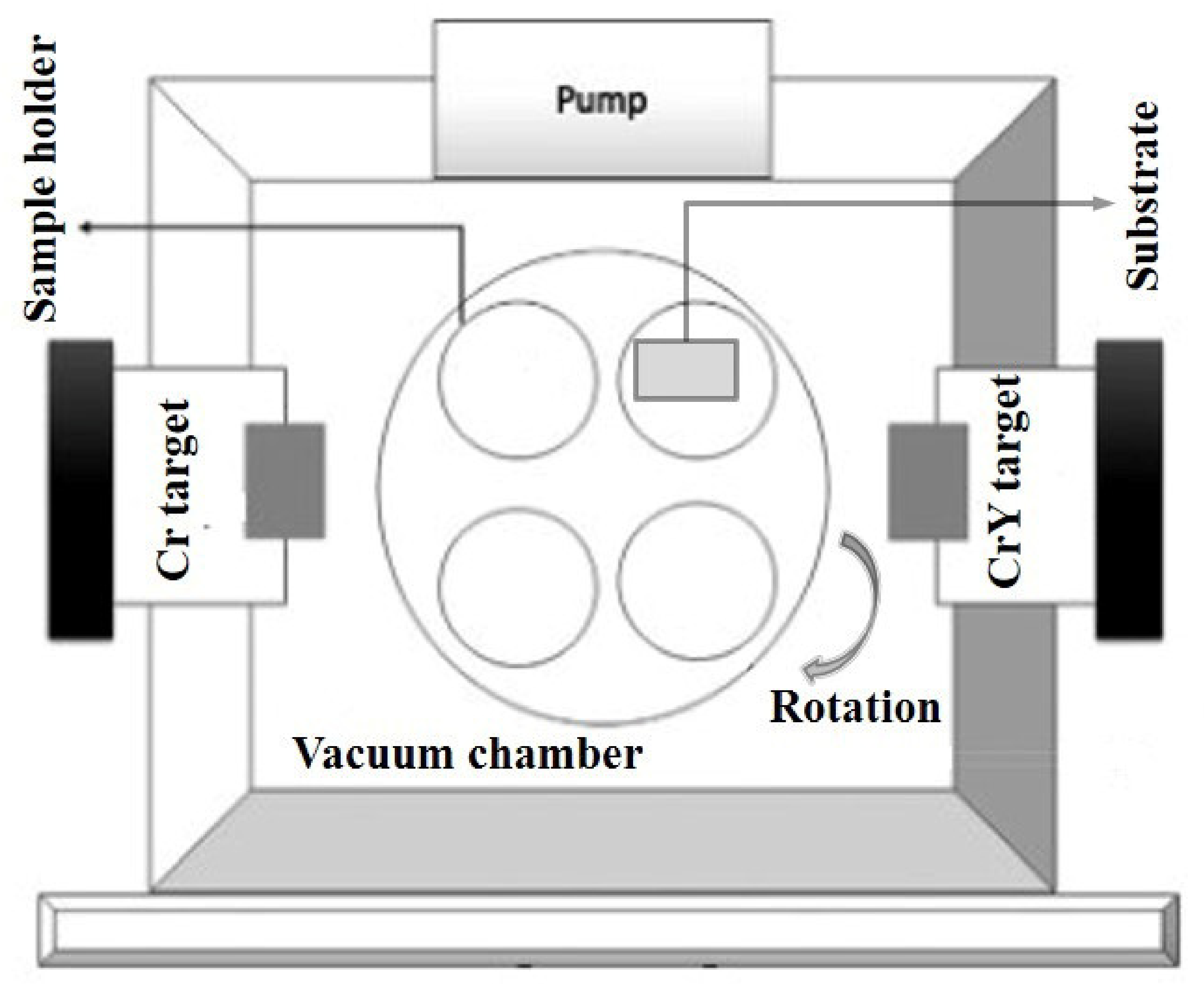
2.1. Coating Deposition
2.2. Characterization of Coating
3. Results and Discussion
3.1. Coating Structure, Morphology and Mechanical Properties
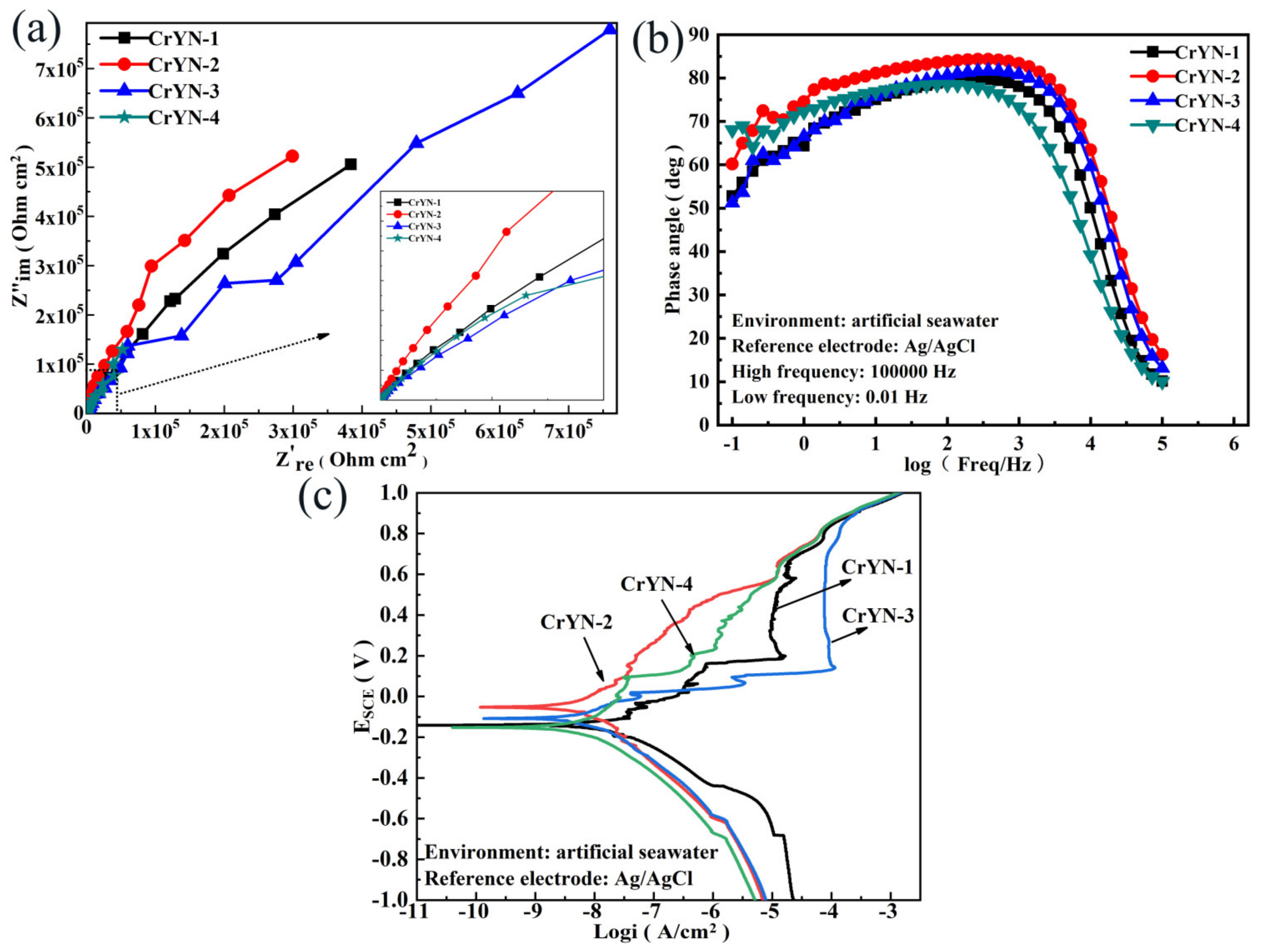
3.2. Corrosion Resistance
3.3. Tribological Properties
4. Conclusions
- (1)
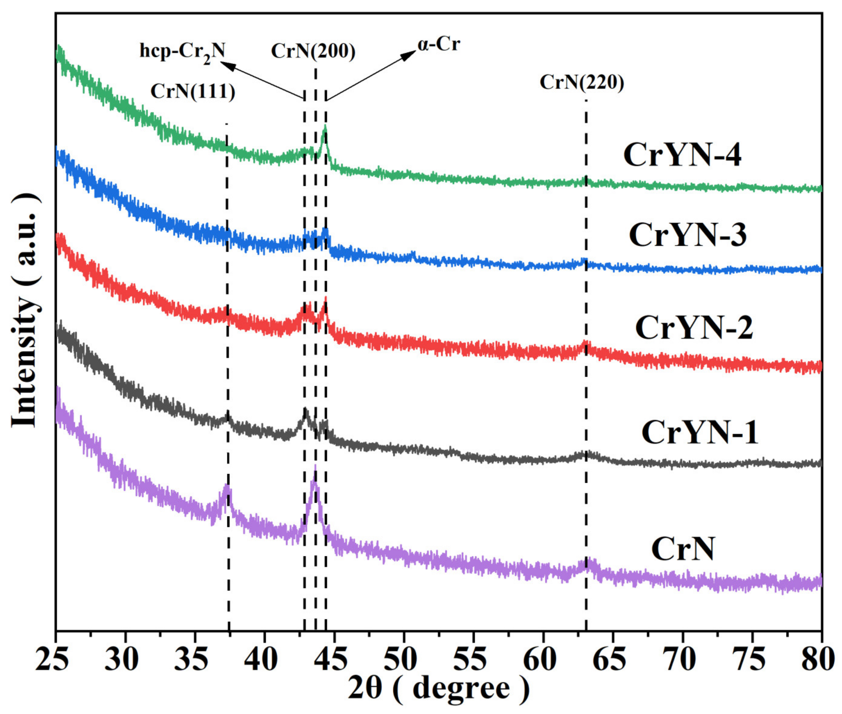
- As the substrate bias voltage increased, the CrN (111), (200), and (220) peak intensities decreased and increased in width at half height;
- (2)
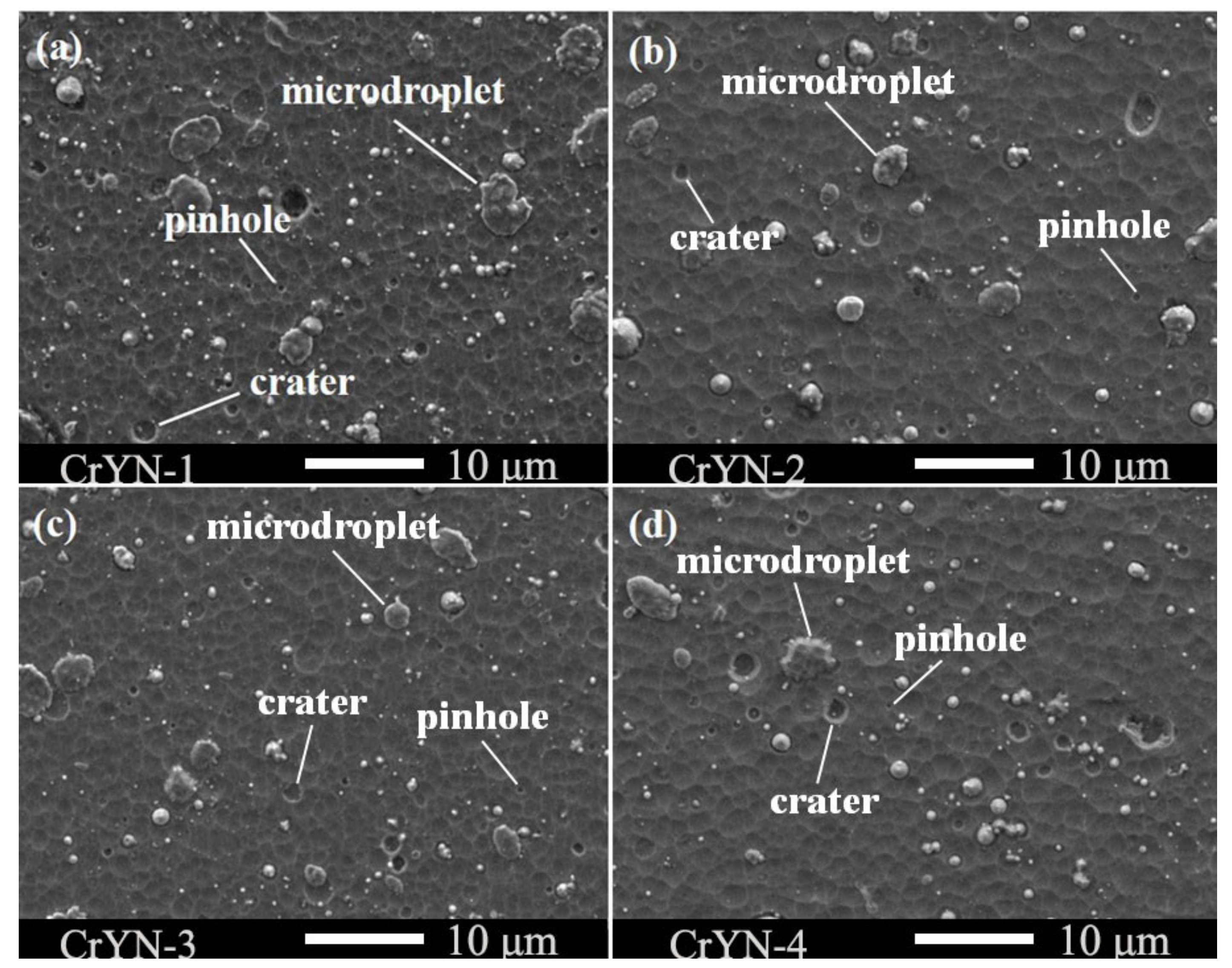
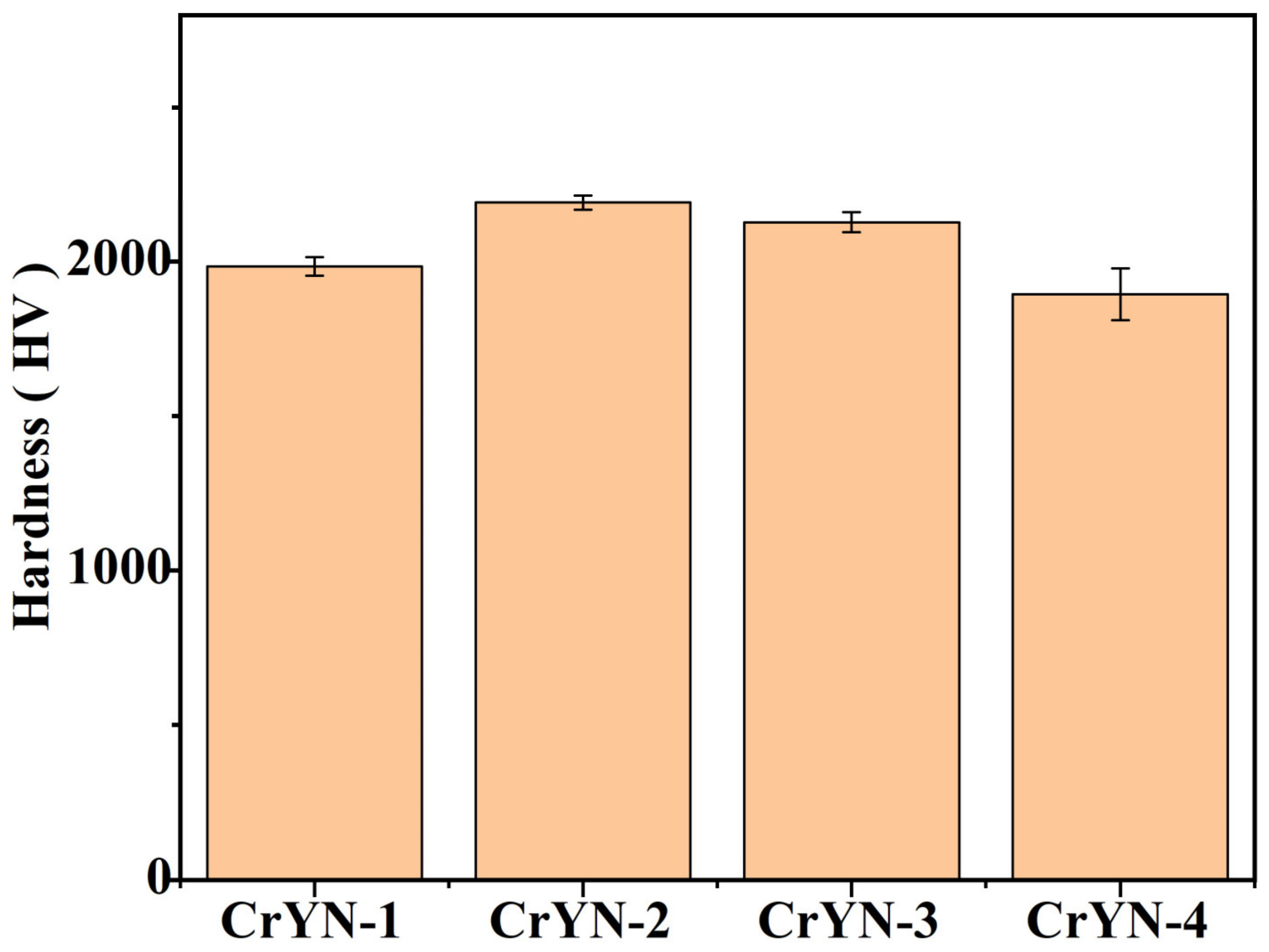
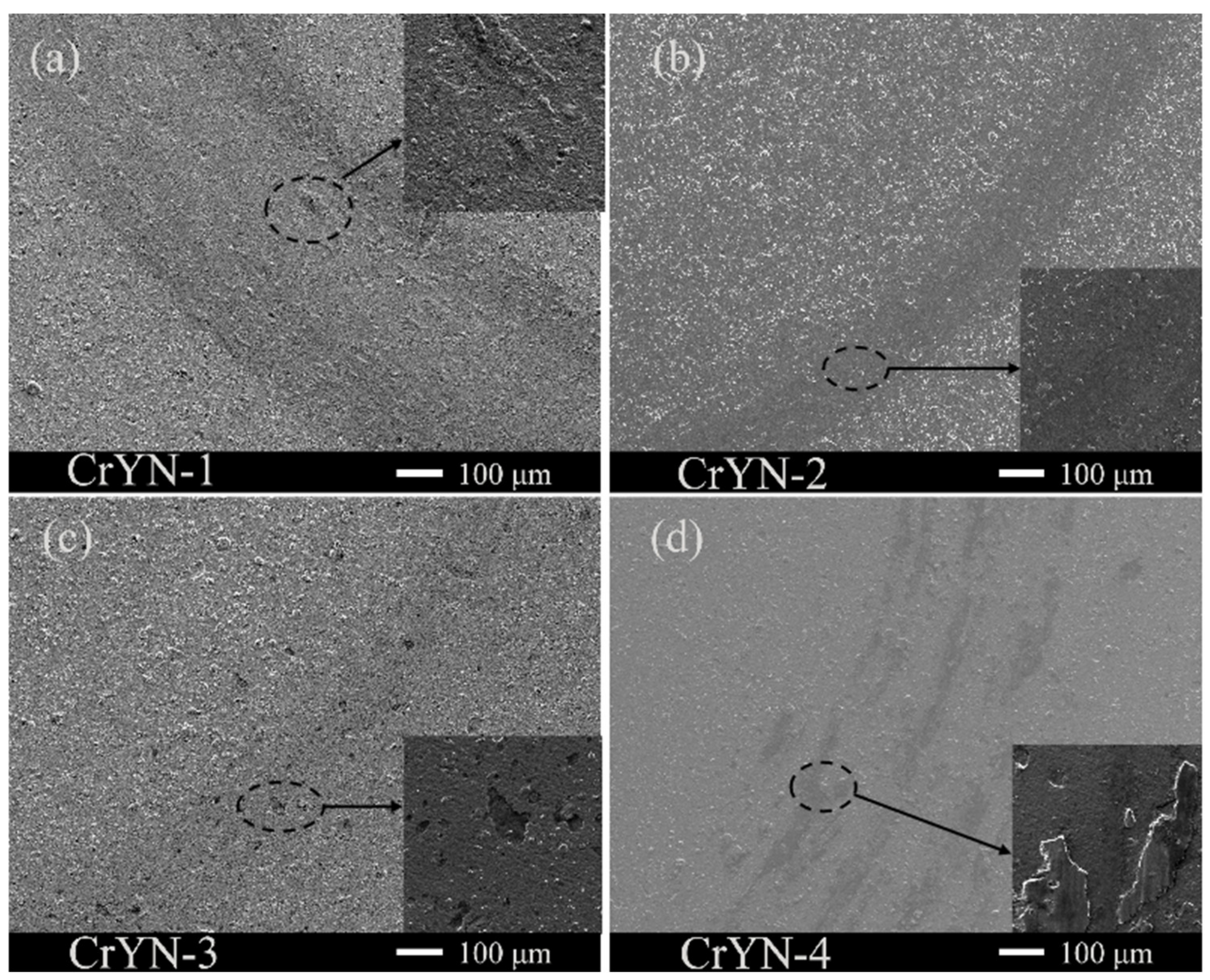
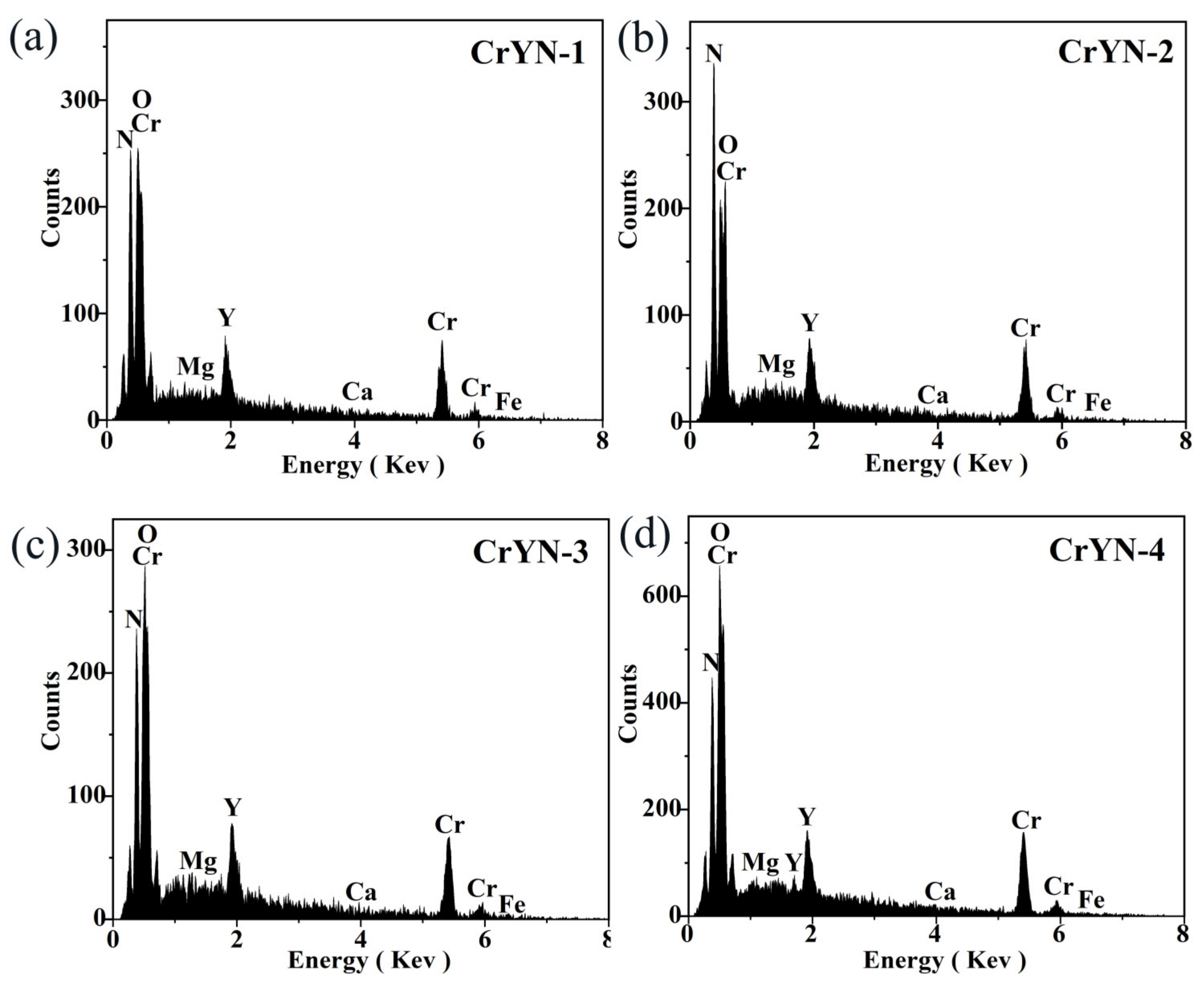
- With increasing bias voltage, using yttrium (Y) in an amorphous form as a dopant restrained the grain growth, refined the grains, and improved the coating quality; moreover, the microhardness increased from 1985 hv to 2192 HV. The surfaces of the CrYN coatings prepared under bias voltages of −100 V and −150 V were smoother and more compact than those of the CrYN coatings prepared under bias voltages of −50 V and −200 V, corresponding to Y contents of 2.83 at.% and 3.1 at.%;
- (3)
- The corrosion resistance of the coatings was mainly related to their surface, compactness, and material components. Electrochemical tests showed that the CrYN coatings deposited at a bias voltage of −100 V had the largest impedance values, the highest corrosion potentials, low self-corrosion currents, and good levels of resistance to electrolytic attack;
- (4)
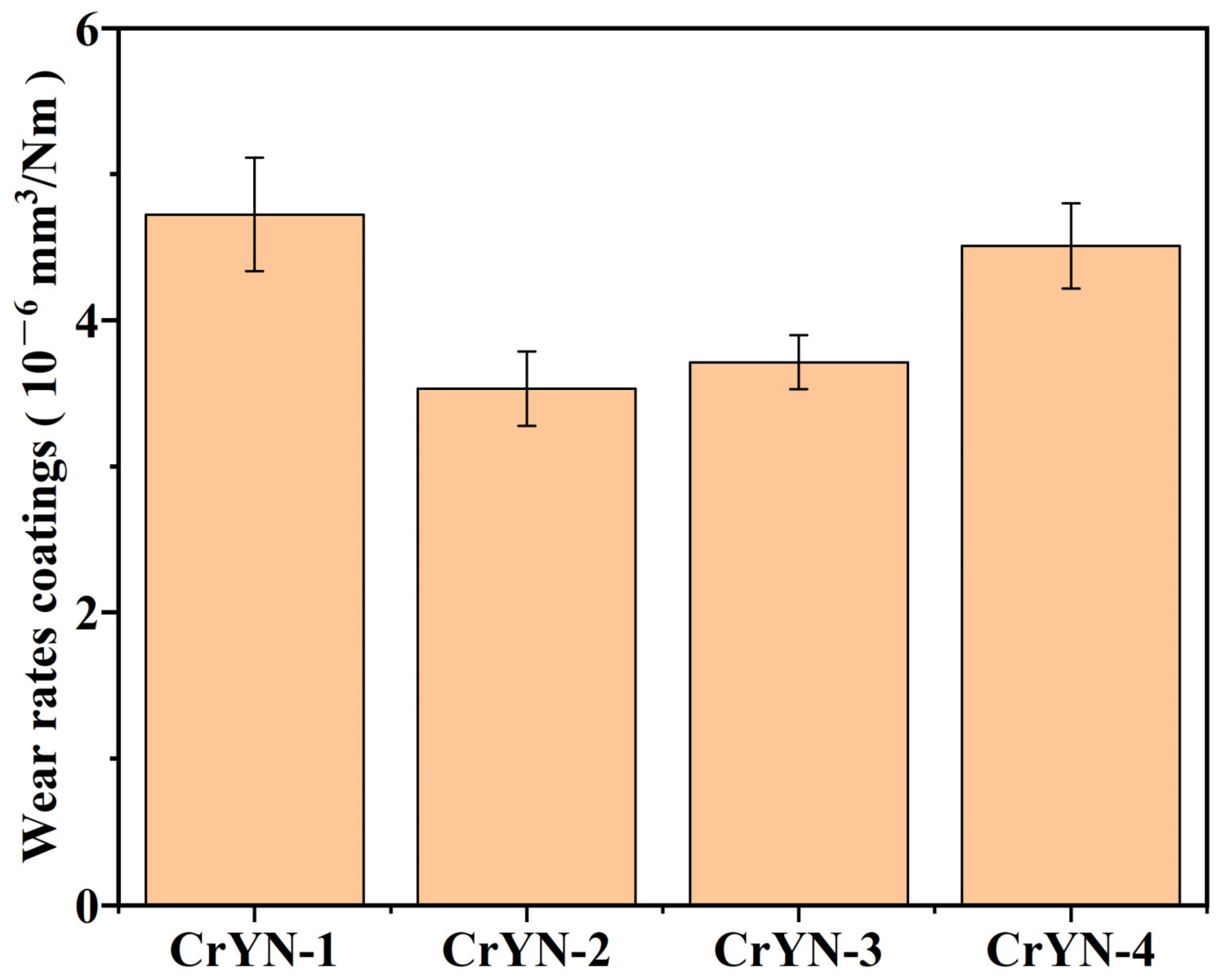
- In an artificial seawater friction test, the friction coefficients of deposited CrYN coatings under −100 V and −150 V bias voltages were all below 0.2, and the wear rates were low. This was mainly because of their dense coating structure and good corrosion resistance. The wear mechanism of CrYN coatings in artificial seawater was shown to be a mix of tribochemical wear and adhesive wear.
Author Contributions
Funding
Data Availability Statement
Conflicts of Interest
References
- Wang, J.; Yan, F.; Xue, Q. Friction and Wear Behavior of Ultra-High Molecular Weight Polyethylene Sliding Against GCr15 Steel and Electroless Ni–P Alloy Coating Under the Lubrication of Seawater. Tribol. Lett. 2009, 35, 85–95. [Google Scholar] [CrossRef]
- Cicek, V. Corrosion and Corrosion Prevention of Metallic Structures in Seawater. In Corrosion Engineering and Cathodic Protection Handbook.; John Wiley & Sons.: Milton, Australia, 2017; pp. 305–308. [Google Scholar]
- Machuca, L.L.; Murray, L.; Gubner, R.; Bailey, S.I. Evaluation of the effects of seawater ingress into 316L lined pipes on corrosion performance. Mater. Corros. 2014, 65, 8–17. [Google Scholar] [CrossRef]
- Du, C.; Bai, X.; Yuan, C. Fretting Tribocorrosion Behaviors of Marine Mooring Chain Steel 22MnCrNiMo in Artificial Seawater. J. Tribol. 2021, 143, 071701. [Google Scholar] [CrossRef]
- Ye, Y.; Liu, Z.; Liu, W.; Zhang, D.; Wang, Y.; Zhao, H.; Li, X. Effect of interlayer design on friction and wear behaviors of CrAlSiN coating under high load in seawater. RSC Adv. 2018, 8, 5596–5607. [Google Scholar] [CrossRef] [PubMed] [Green Version]
- Alkan, S.; Gök, M.S. Influence of plasma nitriding pre-treatment on the corrosion and tribocorrosion behaviours of PVD CrN, TiN and AlTiN coated AISI4140 steel in seawater. Lubr. Sci. 2021, 34, 67–83. [Google Scholar] [CrossRef]
- Zhang, J.; Li, Z.; Wang, Y.; Zhou, S.; Wang, Y.; Zeng, Z.; Li, J. A new method to improve the tribological performance of metal nitride coating: A case study for CrN coating. Vacuum 2020, 173, 109158. [Google Scholar]
- Wu, Z.; Zhou, F.; Ma, Q.; Wang, Q.; Zhou, Z.; Kwok-Yan Li, L. Tribological and electrochemical properties of Cr–Si–C–N coatings in artificial seawater. RSC Adv. 2016, 6, 76724–76735. [Google Scholar] [CrossRef]
- Cai, F.; Yang, Q.; Huang, X. The Roles of Diffusion Factors in Electrochemical Corrosion of TiN and CrN (CrSiCN) Coated Mild Steel and Stainless Steel. In Supplemental Proceedings: Volume 1: Materials Processing and Interfaces; TMS: Pittsburgh, PA, USA, 2012; pp. 49–56. [Google Scholar]
- Bernal, J.L.; Irvin, A.; Vera, E.; Olvera, P.N.; Villanueva, M.; Lasorsa, C.A.; Medina, A.; Bejar, L.; BorJas, S. Microstructural Characterization of Hardened AISI 4140 using CrN/CSi Coatings. Microsc. Microanal. 2017, 23, 416–417. [Google Scholar] [CrossRef] [Green Version]
- Baseri, N.A.; Mohammadi, M.; Ghatee, M.; Abassi-Firouzjah, M.; Elmkhah, H. The effect of duty cycle on the mechanical and electrochemical corrosion properties of multilayer CrN/CrAlN coatings produced by cathodic arc evaporation. Surf. Eng. 2020, 37, 253–262. [Google Scholar] [CrossRef]
- Filippov, A.; Vorontsov, A.; Shamarin, N.; Moskvichev, E.; Novitskaya, O.; Knyazhev, E.; Denisova, Y.; Leonov, A.; Denisov, V.; Tarasov, S. Dry Sliding Friction Study of ZrN/CrN Multi-Layer Coatings Characterized by Vibration and Acoustic Emission Signals. Metals 2022, 12, 2046. [Google Scholar] [CrossRef]
- Iram, S.; Wang, J.; Cai, F.; Zhang, J.; Ahmad, F.; Liang, J.; Zhang, S. Effect of bilayer number on mechanical and wear behaviours of the AlCrN/AlCrMoN coatings by AIP method. Surf. Eng. 2020, 37, 536–544. [Google Scholar] [CrossRef]
- Kim, G.S.; Kim, S.M.; Lee, S.Y.; Lee, B.Y. Comparative studies on the thermal stability and corrosion resistance of CrN, CrSiN, and CrSiN/AlN coatings. J. Vac. Sci. Technol. A: Vac. Surf. Film. 2009, 27, 873–879. [Google Scholar] [CrossRef]
- Konchady, M.S.; Yarmolenko, S.; Pai, D.M.; Sankar, J. In Nanoindentation, Nanoscratch and Wear Studies on Nanoscale Multilayer TiN/CrN Coatings. In Proceedings of the ASME 2009 International Mechanical Engineering Congress and Exposition, Lake Buena Vista, FL, USA, 13–19 November 2009; pp. 55–59. [Google Scholar]
- Luo, P.; Gong, C.; Li, Y.; Wang, X.; Tian, X. Effect of Auxiliary Enhanced Magnetic Field on Microstructure and Mechanical Behaviors of Multilayered CrN/AlCrN Films. J. Mater. Eng. Perform. 2021, 31, 230–239. [Google Scholar] [CrossRef]
- Mundotia, R.; Thorat, N.J.; Kale, A.; Mhatre, U.; Kothari, D.C.; Kovacs, T.; Ghorude, T. Study of corrosion properties of CrN and multilayer CrN/Cr coating at different electrolyte temperatures deposited on stainless steel by vacuum arc process. Dae Solid State Phys. Symp. 2019, 2115, 030313. [Google Scholar]
- Ren, Y.J.; Wen, W.; Chen, J.; Chen, J.L.; Qiu, W.; He, J.J. Corrosion behaviour of nanochromium coatings deposited by direct current magnetron sputtering. Surf. Eng. 2016, 32, 294–298. [Google Scholar] [CrossRef]
- Wu, Z.; Cheng, Z.; Zhang, H.; Xu, Z.; Wang, Y.; Zhou, F. Electrochemical and Tribological Properties of CrAlN, TiAlN, and CrTiN Coatings in Water-Based Cutting Fluid. J. Mater. Eng. Perform. 2020, 29, 2153–2163. [Google Scholar] [CrossRef]
- Aissani, L.; Fellah, M.; Nouveau, C.; Abdul Samad, M.; Montagne, A.; Iost, A. Structural and mechanical properties of Cr–Zr–N coatings with different Zr content. Surf. Eng. 2017, 36, 69–77. [Google Scholar] [CrossRef] [Green Version]
- Selvam, L.; Murugesan, P.K.; Mani, D.; Natarajan, Y. Investigation of AlCrN-Coated Inserts on Cryogenic Turning of Ti-6Al-4V Alloy. Metals 2019, 9, 1338. [Google Scholar] [CrossRef] [Green Version]
- Liu, S.; Ong, B.D.; Guo, J.; Liu, E.; Zeng, X. Wear performance of Y-doped nanolayered CrN/AlN coatings. Surf. Coat. Technol. 2019, 367, 349–357. [Google Scholar] [CrossRef]
- Tritremmel, C.; Daniel, R.; Mitterer, C.; Mayrhofer, P.H.; Lechthaler, M.; Polcik, P. Oxidation behavior of arc evaporated Al-Cr-Si-N thin films. J. Vac. Sci. Technol. A Vac. Surf. Film. 2012, 30, 061501. [Google Scholar] [CrossRef]
- Liu, S.; Wheeler, J.M.; Davis, C.E.; Clegg, W.J.; Zeng, X.T. The effect of Si content on the fracture toughness of CrAlN/Si3N4 coatings. J. Appl. Phys. 2016, 119, 025305. [Google Scholar]
- Correa, J.F.; Caicedo, J.C.; Aperador, W.A. Comparison of Structural and Electrochemical Properties among TiCN, BCN, and CrAlN Coatings under Aggressive Environments. J. Mater. Eng. Perform. 2021, 30, 3586–3602. [Google Scholar]
- Zhang, P.; Shan, L.; Tian, Y.; Su, X.; Luo, L.; Chen, J. Structure and tribological behavior of CrAlCN coating in artificial seawater. Surf. Topogr. Metrol. Prop. 2021, 9, 035028. [Google Scholar]
- Radu, I.; Li, D.Y.; Llewellyn, R. Tribological behavior of Stellite 21 modified with yttrium. Wear 2004, 257, 1154–1166. [Google Scholar] [CrossRef]
- Wu, Z.T.; Qi, Z.B.; Zhu, F.P.; Liu, B.; Wang, Z.C. Influences of Y Addition on Mechanical Properties and Oxidation Resistance of CrN Coating. Phys. Procedia 2013, 50, 150–155. [Google Scholar]
- Rovere, F.; Mayrhofer, P.H. Impact of yttrium on structure and mechanical properties of Cr–Al–N thin films. J. Vac. Sci. Technol. A: Vac. Surf. Film. 2007, 25, 1336–1440. [Google Scholar] [CrossRef]
- Wang, Y.-X.; Wu, S.-L.; Pan, J.; Zhang, X. Effect of Y content on the microstructure, tribological and corrosion properties of CrAlYN coatings deposited by magnetron sputtering. Mater. Res. Express 2019, 6, 096402. [Google Scholar] [CrossRef]
- ASTM D1141-98. Standard Practice for Preparation of Substitute Ocean Water. ASTM: West Conshohocken, PA, USA, 2021.
- ASTM G102-89e1. Standard Practice for Calculation of Corrosion Rates and Related Information from Electrochemi cal Measurements. ASTM: West Conshohocken, PA, USA, 2015.
- Shiao, M.H.; Chang, Z.C.; Shieu, F.S. Characterization and Formation Mechanism of Macroparticles in Arc Ion-Plated CrN Thin Films. J. Electrochem. Soc. 2003, 150, C320. [Google Scholar]
- Goto, H.; Akao, N.; Hara, N.; Sugimoto, K. Pinhole Defect Density of CrNx Thin Films Formed by Ion-Beam-Enhanced Deposition on Stainless Steel Substrates. J. Electrochem. Soc. 2007, 154, C189. [Google Scholar]
- Rovere, F.; Mayrhofer, P.H.; Reinholdt, A.; Mayer, J.; Schneider, J.M. The effect of yttrium incorporation on the oxidation resistance of Cr–Al–N coatings. Surf. Coat. Technol. 2008, 202, 5870–5875. [Google Scholar] [CrossRef]
- Chunyan, Y.; Linhai, T.; Yinghui, W.; Shebin, W.; Tianbao, L.; Bingshe, X. The effect of substrate bias voltages on impact resistance of CrAlN coatings deposited by modified ion beam enhanced magnetron sputtering. Appl. Surf. Sci. 2009, 255, 4033–4038. [Google Scholar] [CrossRef]
- Tlili, B.; Mustapha, N.; Nouveau, C.; Benlatreche, Y.; Guillemot, G.; Lambertin, M. Correlation between thermal properties and aluminum fractions in CrAlN layers deposited by PVD technique. Vacuum 2010, 84, 1067–1074. [Google Scholar] [CrossRef] [Green Version]
- Tjong, S.C.; Chen, H. Nanocrystalline materials and coatings. Mater. Sci. Eng. R: Rep. 2004, 45, 1–88. [Google Scholar] [CrossRef]
- Wan, X.S.; Zhao, S.S.; Yang, Y.; Gong, J.; Sun, C. Effects of nitrogen pressure and pulse bias voltage on the properties of CrN coatings deposited by arc ion plating. Surf. Coat. Technol. 2010, 204, 1800–1810. [Google Scholar] [CrossRef]
- Warcholinski, B.; Gilewicz, A.; Ratajski, J.; Kuklinski, Z.; Rochowicz, J. An analysis of macroparticle-related defects on CrCN and CrN coatings in dependence of the substrate bias voltage. Vacuum 2012, 86, 1235–1239. [Google Scholar]
- Romero, J.; Gómez, M.A.; Esteve, J.; Montalà, F.; Carreras, L.; Grifol, M.; Lousa, A. CrAlN coatings deposited by cathodic arc evaporation at different substrate bias. Thin Solid Film. 2006, 515, 113–117. [Google Scholar] [CrossRef]
- Liu, C.; Bi, Q.; Leyland, A.; Matthews, A. An electrochemical impedance spectroscopy study of the corrosion behaviour of PVD coated steels in 0.5 N NaCl aqueous solution: Part II.: EIS interpretation of corrosion behaviour. Corros. Sci. 2003, 45, 1257–1273. [Google Scholar] [CrossRef]
- Abd El-Rahman, A.M.; Wei, R. Effect of ion bombardment on structural, mechanical, erosion and corrosion properties of Ti–Si–C–N nanocomposite coatings. Surf. Coat. Technol. 2014, 258, 320–328. [Google Scholar]
- Barshilia, H.C.; Prakash, M.S.; Poojari, A.; Rajam, K.S. Corrosion Behaviour of TiN/a-C Superhard Nanocomposite Coatings Prepared by a Reactive DC Magnetron Sputtering Process. Trans. IMF 2017, 82, 123–128. [Google Scholar] [CrossRef] [Green Version]
- Dong, M.; Zhu, Y.; Xu, L.; Ren, X.; Ma, F.; Mao, F.; Wang, L. Tribocorrosion performance of nano-layered coating in artificial seawater. Appl. Surf. Sci. 2019, 487, 647–654. [Google Scholar] [CrossRef]
- Shan, L.; Wang, Y.; Li, J.; Li, H.; Wu, X.; Chen, J. Tribological behaviours of PVD TiN and TiCN coatings in artificial seawater. Surf. Coat. Technol. 2013, 226, 40–50. [Google Scholar] [CrossRef]
- Ye, Y.; Wang, Y.; Chen, H.; Li, J.; Zhou, S.; Xue, Q. Influences of bias voltage on the microstructures and tribological performances of CrCN coatings in seawater. Surf. Coat. Technol. 2015, 270, 305–313. [Google Scholar] [CrossRef]
- Chen, B.; Wang, J.; Yan, F. Friction and Wear Behaviors of Several Polymers Sliding Against GCr15 and 316 Steel Under the Lubrication of Sea Water. Tribol. Lett. 2011, 42, 17–25. [Google Scholar] [CrossRef]


| Bias Voltage/V | Transition Layer CrN/Cr | CrYN | ||||
|---|---|---|---|---|---|---|
| Current/A | Pressure/Pa | Time/min | Current/A | Pressure/Pa | Time/min | |
| −50, −100, −150, −200 | 80 | 2.0 | 10 | 70 | 1.0 | 120 |
| Component | NaCl | KCl | Na2SO4 | NaHCO3 | MgCl2 | KBr | CaCl2 | H3BO3 | SrCl2 | NaF |
|---|---|---|---|---|---|---|---|---|---|---|
| Concentration (g/L) | 24.530 | 0.695 | 4.090 | 0.201 | 5.200 | 0.101 | 1.160 | 0.027 | 0.025 | 0.003 |
| Sample | Composition/at.% | ||
|---|---|---|---|
| Cr/at.% | Y/at.% | Cr/Y% | |
| CrYN-1 | 67.85 | 2.58 | 26.3 |
| CrYN-2 | 68.78 | 2.83 | 24.3 |
| CrYN-3 | 71.66 | 3.1 | 23.1 |
| CrYN-4 | 74.16 | 3.4 | 21.8 |
| Sample | Ecorr (V) | βa (V) | βc (V) | icorr (10−6 A/cm2) | Rp (kΩ·cm2) |
|---|---|---|---|---|---|
| CrYN-1 | −0.141 ±0.020 | 0.134 ±0.022 | 0.158 ±0.019 | 17.051 ±2.740 | 1847 ±211 |
| CrYN-2 | −0.052 ±0.010 | 0.174 ±0.016 | 0.132 ±0.008 | 5.803 ±0.194 | 5620 ±31 |
| CrYN-3 | −0.117 ±0.013 | 0.176 ±0.014 | 0.073 ±0.003 | 4.677 ±0.421 | 4798 ±337 |
| CrYN-4 | −0.151 ±0.010 | 0.158 ±0.009 | 0.150 ±0.005 | 4.976 ±0.470 | 6723 ±526 |
Disclaimer/Publisher’s Note: The statements, opinions and data contained in all publications are solely those of the individual author(s) and contributor(s) and not of MDPI and/or the editor(s). MDPI and/or the editor(s) disclaim responsibility for any injury to people or property resulting from any ideas, methods, instructions or products referred to in the content. |
© 2023 by the authors. Licensee MDPI, Basel, Switzerland. This article is an open access article distributed under the terms and conditions of the Creative Commons Attribution (CC BY) license (https://creativecommons.org/licenses/by/4.0/).
Share and Cite
Li, M.; Yu, Y.; Zou, C.; Tian, C.; Wang, Z.; Xiang, Y. Wear and Corrosion Resistance of CrYN Coating in Artificial Seawater. Metals 2023, 13, 183. https://doi.org/10.3390/met13020183
Li M, Yu Y, Zou C, Tian C, Wang Z, Xiang Y. Wear and Corrosion Resistance of CrYN Coating in Artificial Seawater. Metals. 2023; 13(2):183. https://doi.org/10.3390/met13020183
Chicago/Turabian StyleLi, Man, Yunjiang Yu, Changwei Zou, Canxin Tian, Zesong Wang, and Yanxiong Xiang. 2023. "Wear and Corrosion Resistance of CrYN Coating in Artificial Seawater" Metals 13, no. 2: 183. https://doi.org/10.3390/met13020183