Article

Mathematical Modeling on Optimization of Submerged Entry Nozzle for an Ultra-Thick Slab Continuous Casting Mold

1
State Key Laboratory of Advanced Metallurgy, University of Science and Technology Beijing, Beijing 100083, China
2
School of Metallurgy and Energy, North China University of Science and Technology, Tangshan 063210, China
*
Authors to whom correspondence should be addressed.
Metals 2023, 13(2), 221; https://doi.org/10.3390/met13020221
Submission received: 13 December 2022 / Revised: 20 January 2023 / Accepted: 20 January 2023 / Published: 24 January 2023
(This article belongs to the Special Issue Hot Deformation of Metal and Alloys)

Abstract

:
To optimize the submerged entry nozzle (SEN) for an ultra-thick slab mold, a mathematical model has been established. The molten steel flow and solidification, inclusion transports, and meniscus fluctuation have been investigated through the model. Compared with the concave-bottom SEN cases, the convex-bottom SEN decreases the imping depth of the jet flow and increases the horizontal velocity and temperature on the meniscus. However, the remelting of the solidified shell is dramatic for the convex-bottom case. The well depth of the concave-bottom SEN and the SEN’s submerged depth have little influence on molten steel flow and solidification. The effects of SEN port shape and port angle on the molten steel flow are significant. As the port shape changes from rectangle to square or the port downward angle decreases, the imping depth of jet flow decreases, the horizontal velocity and the temperature on the mold free surface increase. For the ultra-thick mold, a square-shaped-port SEN with a −10° downward angle is more beneficial by comprehensive consideration of molten steel flow and solidification, inclusion removal, and mold powder melting. The optimized SEN has been applied to the actual caster and its performance has been assessed, indicating that the SEN optimization is efficient.

1. Introduction

Heavy plates with excellent performances (mechanical properties, low-temperature impact toughness, and lamellar tearing resistance, etc.) have been extensively applied in high-end equipment manufacturing in the fields of shipbuilding, pressure vessels, offshore platforms, etc. [1]. Generally, the as-cast slabs of the heavy plates are produced through ingot casting [2], vacuum composite welding [3], and continuous casting (CC) [4,5]. To date, some techniques, such as electromagnetic stirring [6] and mechanical reduction (especially heavy reduction) [7,8], have been developed for (ultra-)thick slab CC production. These techniques promote (ultra-)thick slab CC to be the predominant method to produce as-cast slabs for heavy plates [9].
During ultra-thick slab CC, the inactivity of the meniscus often occurs, resulting from the obviously lower casting speeds relative to those of conventional-slab CC [10]. The inactivity of the meniscus of the mold would lead to the insufficient melting of mold powder, which may subsequently result in surface cracks of slabs [11,12]. Furthermore, a relatively uniform growth of a solidified shell in the mold is beneficial for the stable production and high quality of ultra-thick slabs [10,13,14]. Additionally, inclusions existing in the subsurface of the ultra-thick slab deteriorate the machining properties of slabs in the rolling process (acting as a crack initiation) and the performances of the final plates [15]. The molten steel flow pattern in the mold is one of the key factors that influence the problems mentioned above. For ultra-thick slab CC, optimizations of structures and parameters about the SEN is a simple and also realistic way for control or majorization of the flow pattern in the mold, since argon injection into the SEN and in-mold electromagnetic stirring are barely ever applied in practical production. Hence, it is essential to conduct an optimizing study on the SEN for an ultra-thick slab mold for the sake of improving producing stability and product quality of ultra-thick slab CC.
Research on the optimization of the SEN is mainly conducted through physical modeling [10,16,17,18,19,20,21,22,23,24,25,26,27,28] and numerical simulation [10,18,19,20,21,23,24,25,29,30,31,32,33,34,35]. Regarding the SEN in a slab mold, optimizations have been almost performed focused on bottom structure [16,17,36], exit port shape [10,16,19,20,29,30,31,33], submerged depth [17,21,37], and port angle [16,17,29,30]. Additionally, an SEN with a swirl blade [27,28], and a bifurcated SEN with solid barriers attached to the inner bottom [22,38] have been developed to change the flow pattern in the mold. Deng et al. [17] studied the SEN optimization of a slab mold with high casting speed through water model experiments. The effects of SEN bottom structure, port angle, and submerged depth on free surface velocity and level fluctuation have been revealed. Based on the water model results, a concave-bottom SEN with a larger upper port angle has been suggested for high-speed CC, due to its favorable performances of weakening the vortices at the SEN port, reducing slag entrapment, and decreasing free surface velocity. Calderón-Ramos et al. [20] reported that the effect of port shape on the molten steel flow inside the slab mold was significant. Moreover, the SEN with a square port could promote a symmetrical flow in the mold. Wu and Cheng [29] developed a coupling multiphase model to investigate the effects of port angle and port shape on level fluctuation and solidification in a slab mold. The simulation results indicate that the molten steel flow in the mold is mainly influenced by the nozzle port angle. Moreover, as the angle of the port upper face increases, the effective area fraction of the SEN increases, which would lead to a decrease in imping depth, reduction in meniscus turbulence, and uniform solidification. Miranda et al. [37] investigated the effects of the SEN’s submerged depth on the surface velocity and fluctuation at the meniscus through a water model experiment and numerical simulation. The results indicate that the maximum velocity and the wave amplitude at the free surface increase as the submerged depth increases. Moreover, as the submerged depth increases, the maximum and the minimum meniscus levels move towards the SEN. In summary, the purposes of the published works related to optimizations of the SEN in conventional slab molds are to form a stable and symmetry flow pattern, decrease the surface velocity and fluctuation at the meniscus, reduce slag entrainment, and promote a higher-speed casting. Hence, the optimized SEN in the previous work may be not suitable for the ultra-thick slab mold. Nevertheless, optimizations on the SEN for an ultra-thick slab mold, especially if the thickness is larger than 450 mm, have not been reported.
The scope of the current work was to optimize the SEN for an ultra-thick slab mold with a thickness of 475 mm; a mathematical model has been established. The molten steel flow and solidification, inclusion transports, and meniscus fluctuation with different bottoms, port shapes, submerged depths, and port downward angles have been comprehensively investigated through the developed model. Based on the results, the SEN for the ultra-thick slab CC mold has been optimized. The performance of the optimized SEN has been assessed according to the production data and inclusion contents in slabs, indicating that the SEN optimization is efficient.

2. Numerical Methodology

In the present work, some assumptions were considered to simplify the model, which can be seen in the previous works [39,40]. The mathematical model consists of two modules: molten steel flow and heat transfer model and inclusion transports model.

2.1. Flow and Heat Transfer Model of Molten Steel

The flow field of molten steel is solved by the following equations:
u = 0 ,
ρ t ( u ) + ρ ( u u ) = p + ( ( μ + μ t ) u ) + g + S u ,
where u is velocity, ρ is density, p is pressure, g is gravitational acceleration, μ is the laminar viscosity. The turbulent viscosity μ t was computed through the standard k-epsilon turbulent model [41]. Su is a source term for momentum in the mushy zone caused by solidification.
The enthalpy–porosity technique (EPT) [42] was adopted to simulate the heat transfer and solidification of the molten steel. The enthalpy of the steel, H, can be calculated as follows:
H = ( h r e f + T r e f T c p d T ) + f L ,
where href is the enthalpy in reference, Tref is the temperature in reference, cp is constant pressure specific heat. The liquid fraction, f, is calculated as follows:
f = { 1 T > T l T T s T l T s T s T T l 0 T < T s ,
where Ts is solidus temperature, Tl is liquidus temperature.
The conservation equation of enthalpy can be described as follows:
ρ t ( H ) + ρ ( u H ) = ( ( λ + λ t ) T ) ,
λ t = c p μ t Pr t ,
where λ is conducting coefficient of heat, λ t is turbulent conducting coefficient of heat. Pr t is turbulent Prandtl number, which is set as 0.85 by default.
The source term of momentum in the mushy zone caused by solidification, Su, is solved as:
S u = ( 1 f ) f 3 + e A m u s h ( u u p ) ,
where e is set as 0.001 to prevent floating point division by zero, A m u s h is mushy zone constant (set as 1 × 10⁸ [43]), and u p is pouring velocity.

2.2. Inclusion Transports Model

To study the effect of SEN parameters on inclusion removal in the mold, a numerical formulation for inclusion transports has been adopted. The trajectories of inclusions injected into the mold are tracked by solving the particle force balance equation in the Lagrangian reference frame, as follows:
ρ i n π 6 d i n 3 d u i n d t = F b + F d + F p + F l + F v m ,
where ρ i n is inclusion density, d i n is inclusion diameter, u i n is inclusion velocity. F b , F d , F p , F l , F v m are buoyancy force, drag force, pressure gradient force, lift force, and virtual mass force, respectively, of which the details can be found in the previous work [40,44].

2.3. Geometry Model, Mesh, and SEN Structures

As Figure 1a shows, to save the computation cost, a quarter geometry model of the strand has been considered. Moreover, to obtain a fully developed and stable outflow from the mold, the computational domain has been extended to 3 m from the meniscus, which includes SEN, mold region (0.8 m in length), foot roller zone (FRZ, 0.29 m in length), and part of the secondary cooling zone (SCZ, 1.91 m in length). The computational domain is divided into approximately 800,000 cells to generate a structured grid used in calculations. To accurately calculate the solidification and capture the solidification front, local grids near the wall regions were refined.
Figure 1b shows the SENs with different bottoms and ports considered in the current work. A concave-bottom SEN with a well depth (Dw) of 27.5 mm, whose port is rectangular in shape (H95 × L60), is used in the field production before optimization. The SENs with different bottoms have the same port structure, which is a rectangle with a size of 95 × 60 mm. Additionally, the port areas of SENs with different port structures are consistent. Moreover, the same concave bottom with a well depth of 27.5 mm has been adopted for the SENs with different port structures. The parameters for materials, geometrical sizes, and operations used in the simulations are listed in Table 1.

2.4. Boundary Conditions

The boundary conditions used in the computations of flow and heat transfer are detailed in Table 2. Velocity at the inlet is set as a fixed value according to the throughput of molten steel. A fixed wall velocity boundary condition, of which the magnitude is equal to the casting speed, is applied for the broad face (BF) and narrow face (NF) of the domain. The value of pressure at the outlet is set as zero. The fixedValue boundary condition is adopted to turbulent parameters (k and ε) at the inlet [40]. Wall function (WF) is applied for the walls in the calculations. In the mold, the heat flux q m can be expressed as:
q m = a b t ,
where t is the residence time of molten steel from the meniscus. The constants, a and b are determined according to the temperature difference and the flow rate of cooling water of mold [45].
In the FRZ and SCZ, the heat flux across the strand surface, q s , can be defied as follows:
q s = h t ( T s T w ) ,
where ht is coefficient of heat transfer [46], Ts is the strand surface temperature, Tw is the spray cooling water temperature.
With reference to the computations of the inclusion transports, inclusions are uniformly injected into the calculation domain from the inlet. The injection rate of inclusions is 500 s−1. The reflect boundary condition is applied for all walls during the calculations of inclusion transports. Additionally, when inclusions touch the mold top surface and the outlet, inclusions would escape and not be tracked in the later computation.

2.5. Numerical Procedure Details

In the present work, the computations were performed through OpenFOAM 7, an open-source computational fluid dynamics package. The mathematical model was established based on the official solver pimpleFoam in OpenFOAM. During the computations, the maximum Courant number, which was set as 0.5, was adopted to adjust the time step. To save the computation cost, the heat transfer of molten steel was not solved during the computations of inclusion transports. For each case, the calculation period is 600 s. The simulations were conducted using a workstation with two AMD EPYC 7402 CPUs with 2.8 GHz basic frequency. Approximately 30 h were required to conduct the simulation for each case utilizing 24 cores.

3. Results and Discussion

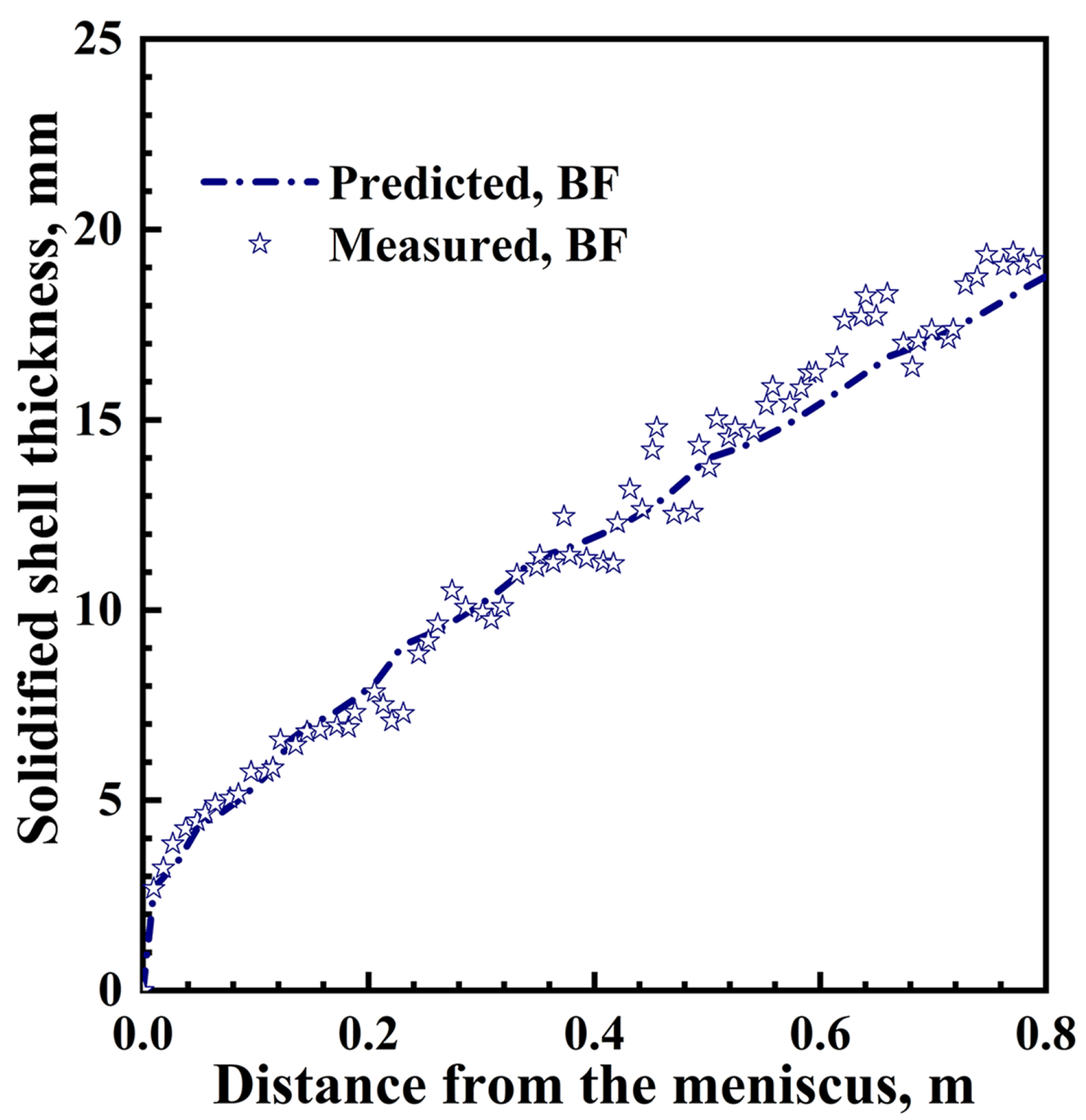
3.1. Model Validation

In the current work, to validate the solidification model, a numerical calculation has been performed through the developed model according to the conditions detailed in the previous work [47]. As shown in Figure 2, the predicted results about solidified shell thickness have been compared with the measurements on a shell after breakout [47]. A good agreement could be found between the predicted results and the measurements, which verified the validity of the mathematical model used in the current study.

3.2. Effects of SEN Bottom and Port Structure on Flow, Heat Transfer, and Inclusion Removal

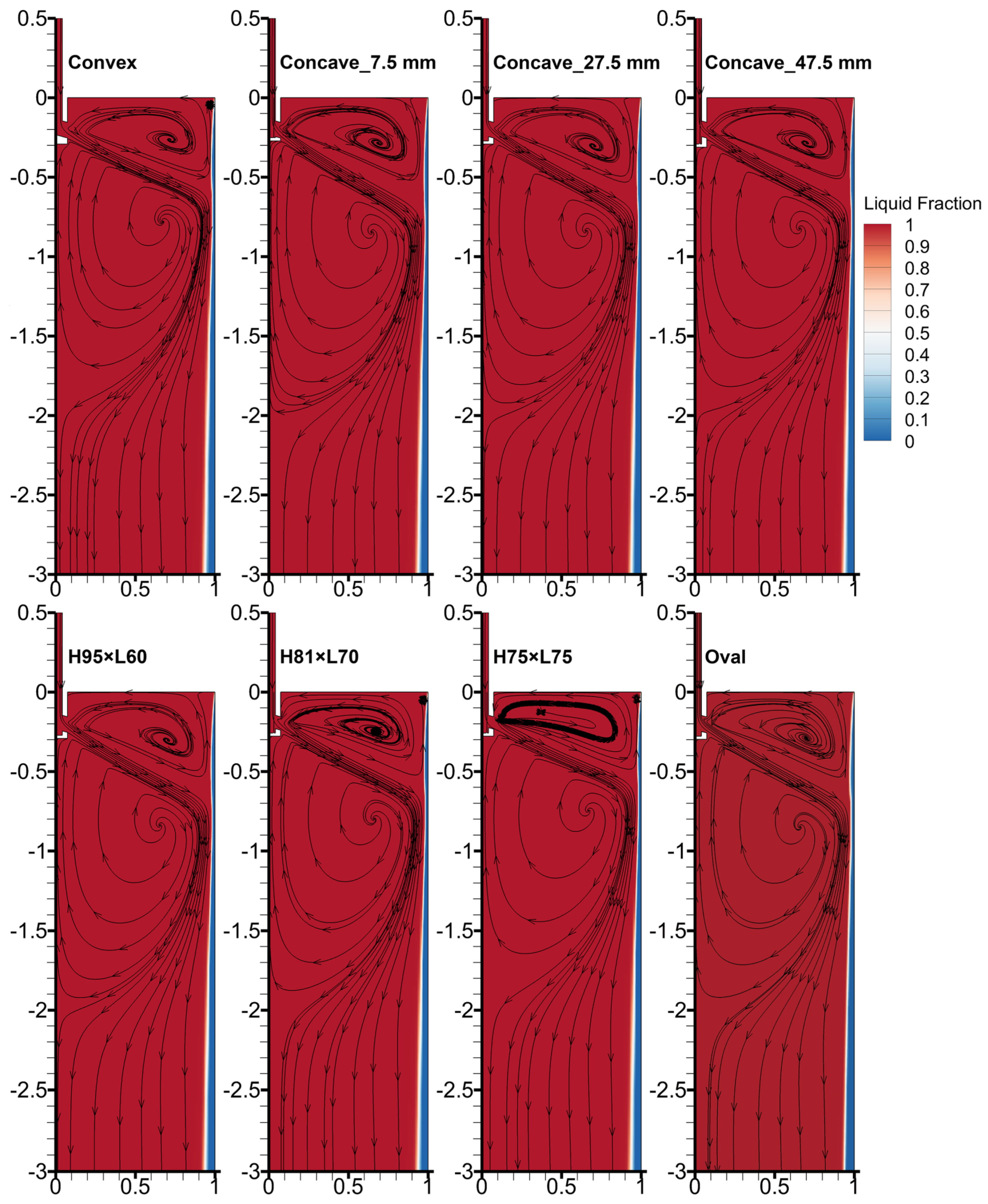
3.2.1. Molten Steel Flow Field and Temperature Distribution

Figure 3 shows the flow field and steel liquid fraction on the mold mid-thickness plane with different SEN structures. The submerged depth and port angle of SENs in these cases are consistent, which are 155 mm and −15°, respectively. Classical “double-roll” flow pattern, upper recirculation zone (URZ), and lower recirculation zone (LRZ), can be found in the mold for different conditions of the SEN structures. Moreover, the remelting of the solidified shell at NF can be seen for each case. When the bottom of the SEN is convex, the flow pattern is different from those cases with a concave bottom. Compared with the cases with concave bottoms, the angle of the imping jet out from the SEN port decreases under the condition that the SEN is a convex bottom. As a result, the LRZ for the convex-bottom case elevates relative to those cases with concave bottoms. It can be found that the well depth of a concave-bottom SEN has little influence on the molten steel flow in the mold cavity. However, the effect of the SEN port shape on the molten steel flow is significant. As H decreases and L increases, the angle of jet flow decreases, and the vortices of URZ and LRZ raise gradually, which leads to reducing of the URZ. In addition, as Figure 3 shows, molten steel flow in the oval-port SEN case is almost consistent with that in the rectangle-port SEN (H95 × L60) case.
Figure 4a,c show the longitudinal velocity variations near the NF solidification front (x = 0.95 m) along the casting direction on the mold mid-thickness plane with different SEN bottoms and port shapes. As shown in Figure 4c, an index Di [48], which is the longitudinal distance from the meniscus to the location where Uz is zero, has been applied to evaluate the imping depth of the molten steel jet flow. Furthermore, the LRZ and URZ can be clearly distinguished, as Figure 4c presents. Molten steel flows inside the SEN with a convex bottom and crashes the tip of the convex bottom. Then, the stream is divided into two parts, which flow into the mold from each port. Nevertheless, the concave bottom, which is similar to the turbulence inhibitor in the tundish [36], has an inhibition on the molten steel flow inside the SEN. The kinematic energy loss of molten steel inside the concave-bottom SEN is significantly higher than that inside the convex-bottom SEN. Therefore, as Figure 4a shows, the molten steel flow in the case with a convex bottom is obviously stronger than those in the cases with concave bottoms. As a result, the value of Di for the convex case is lower than those for the other three cases. Moreover, the velocity of molten steel near the solidified shell for the convex-bottom case is larger than those for the cases with concave bottoms. In addition, the effect of well depth on the molten steel flow is relatively gentle. As the well depth increases, the inhibition on the flow increases. Consequently, the value of Di decreases, and the velocity near the solidified shell also decreases. As Figure 4c demonstrates, the influence of the SEN port shape is apparent. It can be found that a square port shape (H75 × L75) possesses a lower Di value. Moreover, for this type of SEN port shape, the upward velocity in the URZ is relatively larger and the downward velocity in the LRZ is relatively smaller. Nevertheless, the situations for the SEN with an oval-shaped port are just the opposite.
Figure 4b,d reveal the effects of SEN bottom and port shape on the horizontal velocity variations at the mold free surface. Based on the above analysis, it is easy to find that the surface velocity on the meniscus in the case with a convex bottom is larger than those in cases with concave bottoms. Moreover, a square-port SEN can also intensify the horizontal flow on the mold free surface. The horizontal velocity of molten steel at the mold free surface, is a key parameter for CC production and surface quality of slabs. The freezing of molten steel near the meniscus and inadequate melting of mold flux would occur if the value is too low. However, a too-high value would lead to excessive level fluctuation and even slag entrainment. Some scholars [36,49] suggested a favorable range for the surface velocity, which is 0.1–0.4 m·s−1. With reference to ultra-thick slab CC, the surface velocity on the meniscus first needs to be larger than 0.1 m·s−1. Based on this consideration, an SEN with a convex bottom or square-shaped port is more favorable. However, the surface velocities in the cases with convex-bottom or square-shaped SENs are still lower than 0.1 m·s−1, which should be further optimized.
Figure 5 presents the temperature distributions on the meniscus under different conditions of SEN bottoms and port shapes. A convex-bottom SEN leads to a small Di, and an intensified flow in the URZ. As a result, the temperature on the mold free surface is higher than the cases with concave bottoms. For SENs with concave bottoms, a larger well depth results in a greater inhibition on the imping jet of molten steel and a weaker flow in the URZ. Hence, as the well depth increases, the temperature of molten steel on the meniscus reduces. By the same token, for cases with different port shapes, an SEN with a square-shaped port (H75 × L75) results in a higher temperature of molten steel on the mold free surface, which is beneficial for the melting of mold powder.

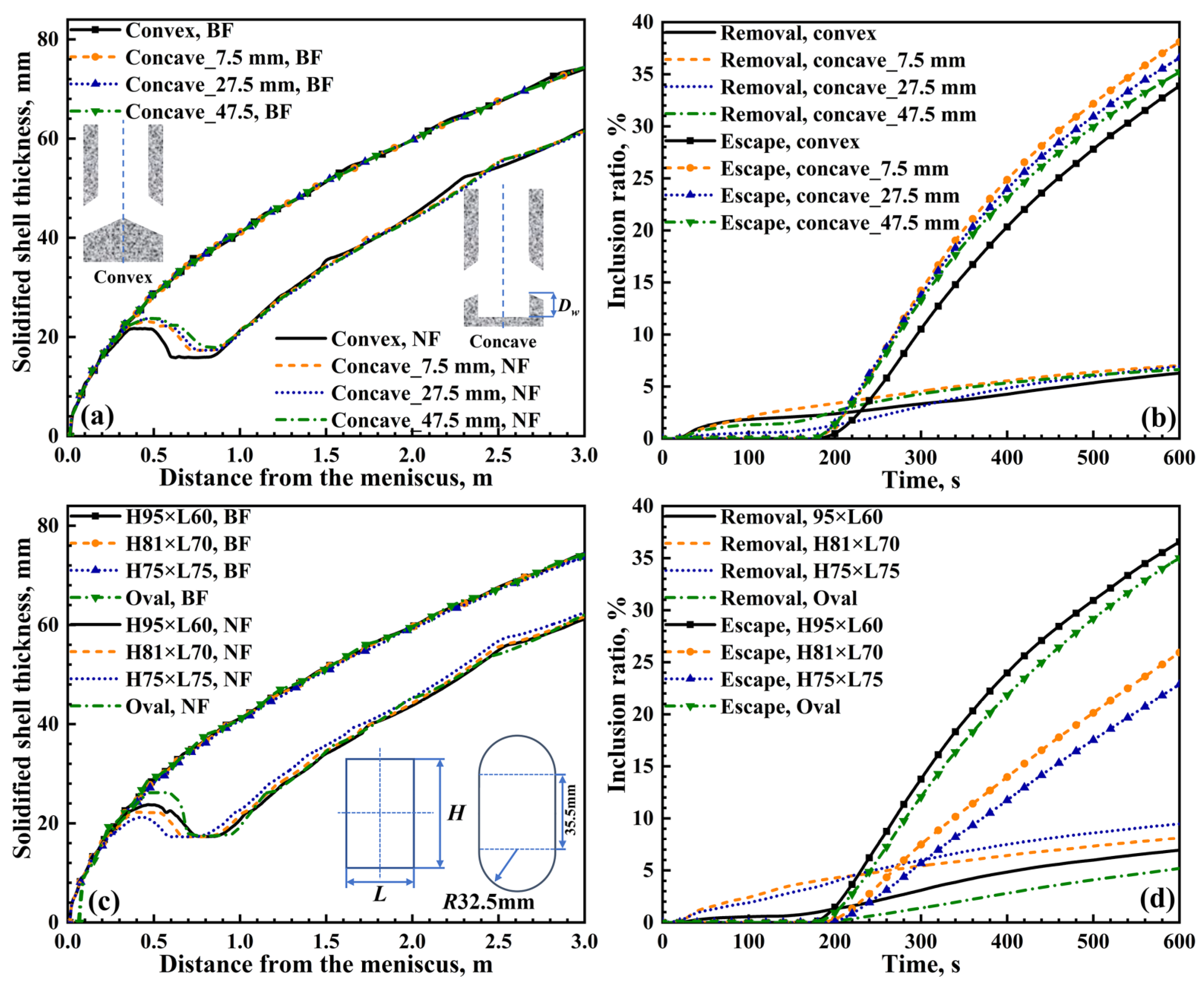
3.2.2. Solidified Shell Thickness and Inclusion Removal

Figure 6a,c show the solidified shell distributions along the casting direction with different SEN bottoms and port shapes. It can be observed that the effects of the SEN bottom and port shape on the solidified shell thickness at the BF center can be neglected. Due to a lower Di value and a more intensified flow near the NF solidification front, the remelting of the NF solidified shell initiates at a position closer to the meniscus for the convex-bottom case. Moreover, the remelting zone of the solidified shell for the convex-bottom case is the largest among the four different SEN bottom cases. As a result, the NF solidified shell at the mold exit for the convex-bottom case is the thinnest, which may lead to breakout during CC. As mentioned above, the well depth has little effect on the molten steel flow pattern in cases with concave bottoms. Similarly, its effect on the solidification is slight. The concave bottom can weaken the jet flow of molten steel. As the well depth increases, the weakening effect increases slightly, then the remelting of the solidified shell can be alleviated to a certain extent. As shown in Figure 4c, among four cases with different SEN port shapes, the value of Di and the downward velocity in the LRZ for the case with a square-shaped-port SEN are the lowest. Hence, for the square-port-shape case, the remelting of the NF solidified shell appears early. Moreover, the remelting range of solidified shell for the square-port case is the smallest among the four different SEN port cases. Consequently, the NF solidified shell at the mold exit for the square-port case is the thickest, which is beneficial for production safety and slab quality.
Two parameters have been recorded during the calculations of inclusion transports, which are the ratio of inclusion removing from the meniscus and the ratio of inclusion escaping from the domain outlet. Figure 6b,d show the predicted inclusion ratios of removal and escape with different SEN bottoms and port shapes. Compared with the effect of SEN bottom on inclusion transports, the effect of SEN port shape on inclusion transports is more significant. For the case with a square-shaped port, the value of Di and the downward velocity in the LRZ are the lowest. As a result, while inclusions are carried into the mold by the imping jet of molten steel, more of them can move into the URZ and float up to the meniscus rapidly, then be absorbed by the mold flux. Furthermore, fewer number of inclusions can be transported into the liquid pool of the lower part of the mold region. Hence, the ratio of inclusion escape is the lowest for the case with a square-shaped port. In a word, the SEN with a square-shaped port is more advantageous for inclusion removal in the mold.

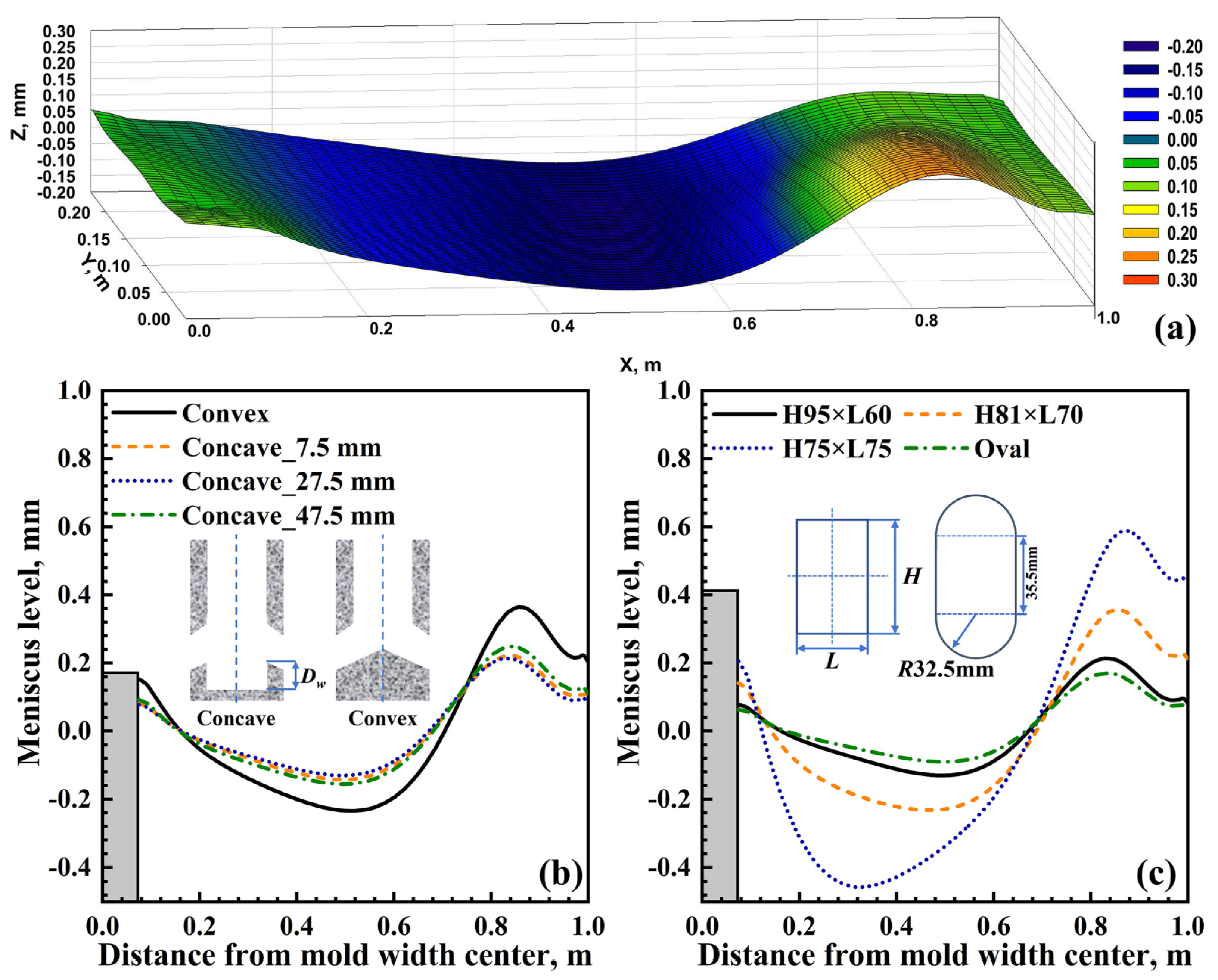
3.2.3. Meniscus Level Profiles

In order to evaluate the influence of SEN structure on the level fluctuation of the meniscus, the displacements of meniscus Δz was calculated according to the equation as follows [50]:
Δ z = p ( x , y ) p m e a n ( ρ ρ s l a g ) g ,
where p ( x , y ) is the pressure at each point of the free surface, p m e a n is the average pressure of the meniscus, ρ s l a g is the density of the mold flux.
Figure 7 shows the calculated 3D meniscus level profile for the concave-bottom case with 27.5 mm well depth and meniscus level profiles on the mid-thickness plane of the mold under different conditions. As Figure 7a shows, the maximum of Δz appears at the position near the NF, resulting from the upward flow of molten steel in the URZ. Moreover, the minimum of Δz locates between the SEN and the quarter of the mold width. Additionally, the fluctuation can hardly be found near the SEN, especially the zone between the SEN and BF, which is adverse for the melting of mold powder. As shown in Figure 7b, due to a more intensified flow in the URZ, the convex bottom makes a relatively larger level fluctuation of the meniscus. Figure 7c reveals the effect of the SEN port shape on the level fluctuation of the mold free surface. It is easy to find that the influence of the SEN port shape on the meniscus fluctuation is more obvious, due to its significant impact on the molten steel flow pattern. The square-port SEN generates a more distinct meniscus fluctuation. Nevertheless, the optimal range for the level fluctuation in the mold is <±3 mm, according to correlational research [51] and practical production experience. Hence, the fluctuations of different cases shown in Figure 7b,c are far from reaching the upper limit.

3.3. Optimizations of Submerged Depth and Port Angle of Square-Port SEN

As analyzed above, it is concluded that the SEN with a square port (H75 × L75) is more beneficial for ultra-thick slab CC. However, as shown in Figure 4d, the horizontal velocity at the meniscus is still lower than 0.1 m·s−1, which is lower than the lower limit of the suggested range (0.1–0.4 m·s−1). The SEN optimization should be further conducted. Hence, the current work has performed optimizations for the square-port SEN in terms of submerged depth and port angle.

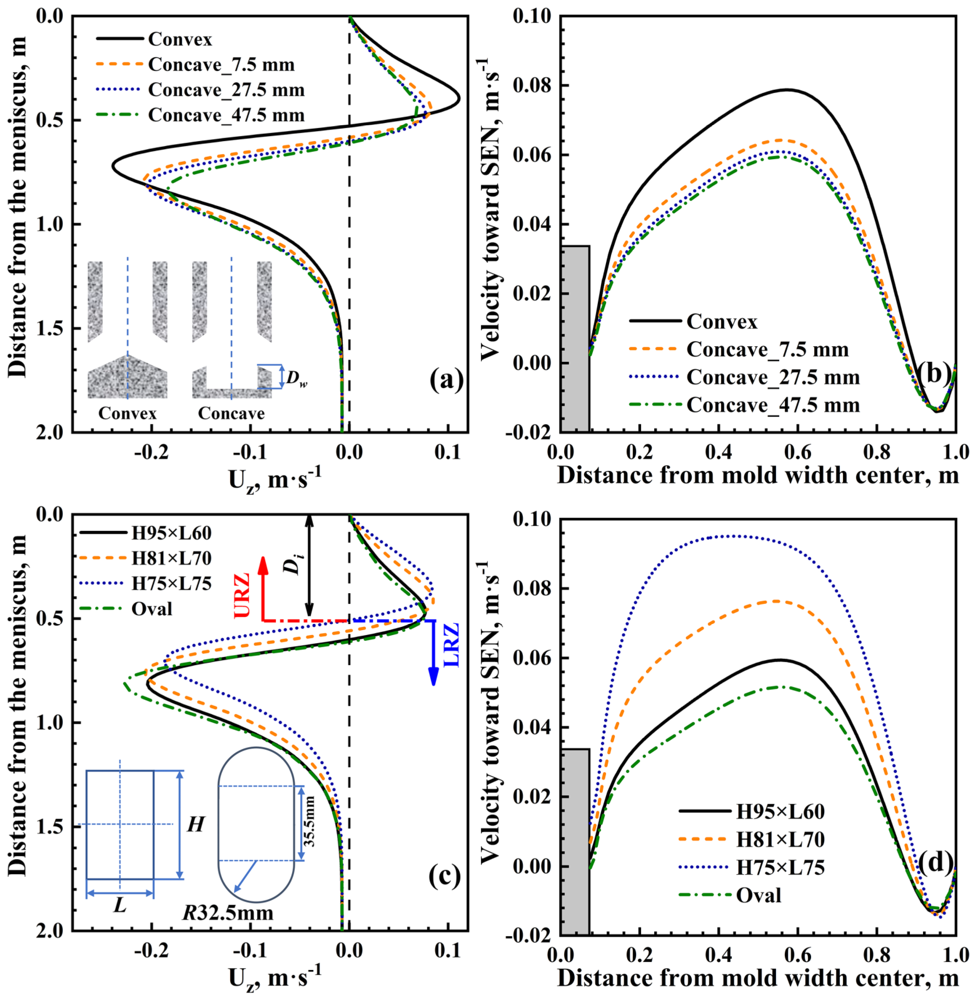
3.3.1. Effects of Submerged Depth and Port Angle on Flow and Heat Transfer

Figure 8 shows the longitudinal velocity profiles near the NF solidification front along the casting direction and horizontal velocity variations on the meniscus with different SEN submerged depths and port angles. As shown in Figure 8a,b, it can be found that the SEN’s submerged depth has a tiny influence on the molten steel flow. Furthermore, in the scope of the current work, the maximum surface velocity at the meniscus decreases as the submerged depth decreases. Similar results have also been reported by other scholars [17,37]. This may be caused by the insufficient development of the flow in URZ as the submerged depth decreases. Hence, the effect of the SEN’s submerged depth will not be discussed.
Figure 8c,d indicate that the SEN port angle has a significant influence on the molten steel flow. As the downward angle of the port increases, the imping depth of molten steel jet flow obviously increases, and the flow in the URZ changes to be gradually weakened. While the downward angle is changed from −20° to −10°, the horizontal velocity on the meniscus significantly increases. However, when the port angle is −5°, the horizontal velocity decreases, compared with the case with a port angle of −10°. Moreover, relative to other cases, the variation trend in the horizontal velocity along the mold width direction is unique while the port angle is −5°. It should be mentioned that the horizontal velocity reaches the optimal range (0.1–0.4 m·s−1) only in the case with a port angle of −10°.
As shown in Figure 9, the molten steel flow pattern in the case with a −5° port angle is different from that in other cases. The imping jet is divided into two parts after exiting the port. One part of the jet travels across the mold and generates the URZ and LRZ. However, the other part of the jet disperses at the port, and spreads toward the NF. At last, this part of molten steel encounters the upper recirculation flow at the quarter of the mold width approximately. The type of flow pattern is likely to form a flow dead zone, which is adverse for heat transfer to the meniscus and the meniscus activation. Moreover, this flow pattern leads to the unique variation trend in the horizontal velocity shown in Figure 8d. As Figure 9 demonstrates, due to a lower imping depth and a stronger flow of molten steel in the URZ, the −10° port angle generates a more favorable temperature distribution on the meniscus with a larger high-temperature zone. For the case with a −5° port angle, a relatively lower temperature zone appears around the SEN, resulting from the special flow pattern of molten steel.

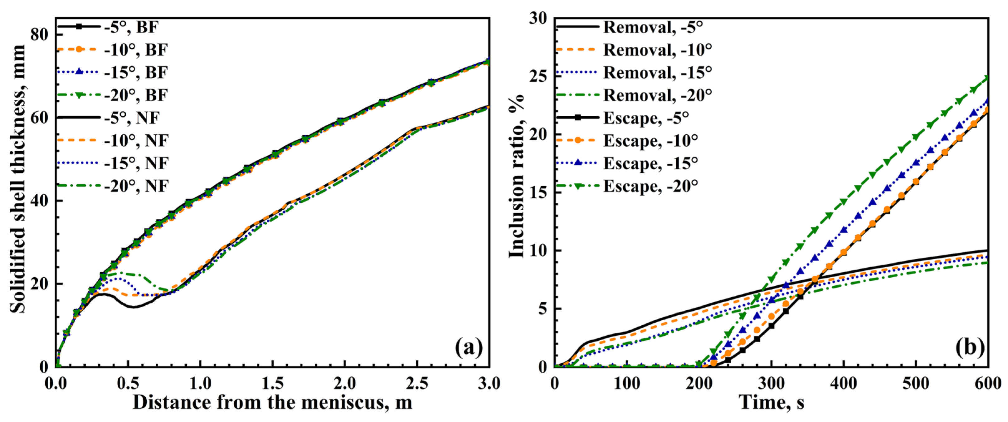
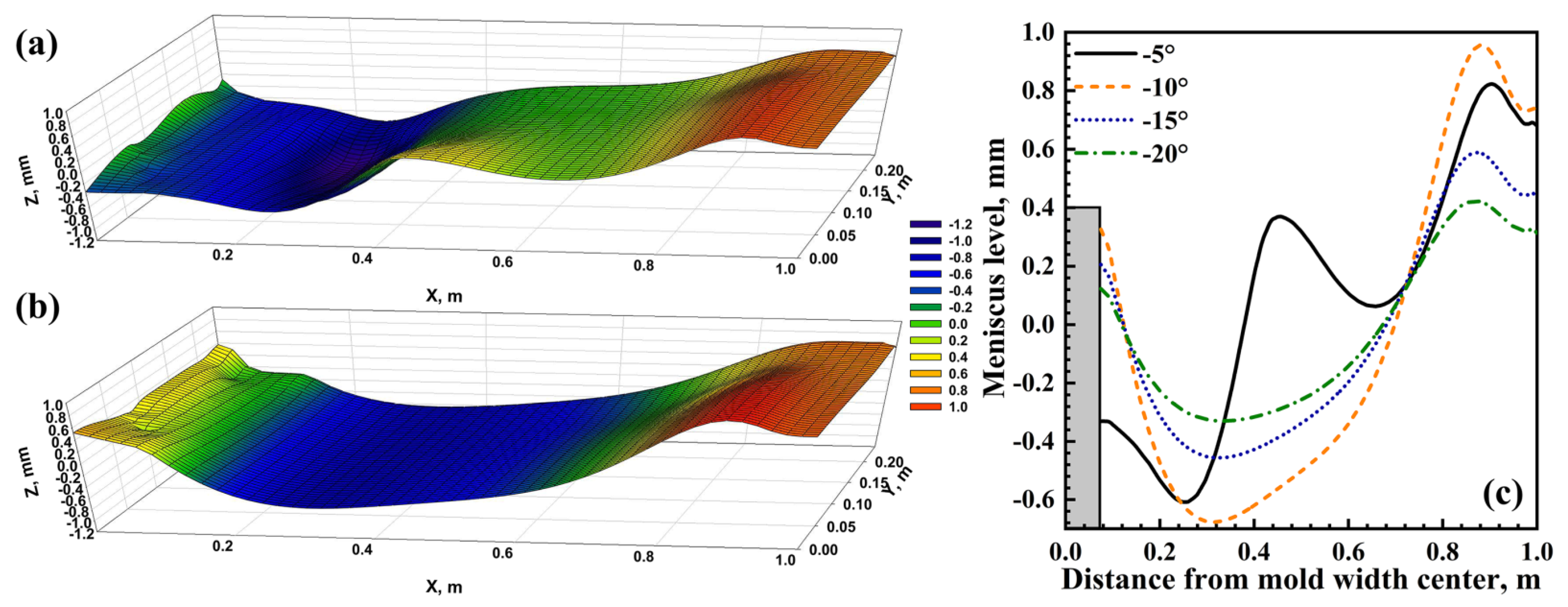
3.3.2. Effects of Port Angle on Solidified Shell, Inclusion Removal, and Meniscus Level

Figure 10a shows the solidified shell distributions along the casting direction with different port angles of the square-port SENs. Similarly, the effect of the port angle on the molten steel solidification is more obvious for the NF. As the downward angle increases, the imping position on the NF moves down, which is not favorable out of the consideration of the prevention of breakout. Nevertheless, while the downward angle is too little, the impacts of the jet out from the port and the upward jet in the URZ on the NF solidified shell would be intense, resulting in premature remelting of the solidified shell. Hence, a moderate downward port angle, −10°, is recommended for the molten steel solidification in the ultra-thick slab mold.
Figure 10b shows the predicted inclusion ratios of removal and escape with different port angles of the square-port SENs. As the downward port angle decreases, inclusions are easier to be transported into the URZ and float up to the meniscus. While the downward port angle changes from −10° to −5°, the variations in the inclusion removal ratio and inclusion escape ratio are tiny. Hence, for the sake of inclusion removal, both −5° and −10° are recommended for the downward port angle.
Figure 11 shows the calculated meniscus level profiles with different port angles of the square-port SENs. Similarly, in the cases with −10°, −15°, and −20° port angles, the maximum and minimum of Δz appear at the position near the NF and the position between the quarter of the mold width and the SEN, respectively. Additionally, as the port angle increases from −20° to −10°, the fluctuation of the meniscus is intensified gradually. However, the level profile changes when the port angle is −5°, and a peak appears at the quarter of mold width, where two parts of the jet flow out from the port encounters, as shown in Figure 9. Moreover, it should be pointed out that the fluctuations in the four cases are all within the optimal range (<±3 mm).

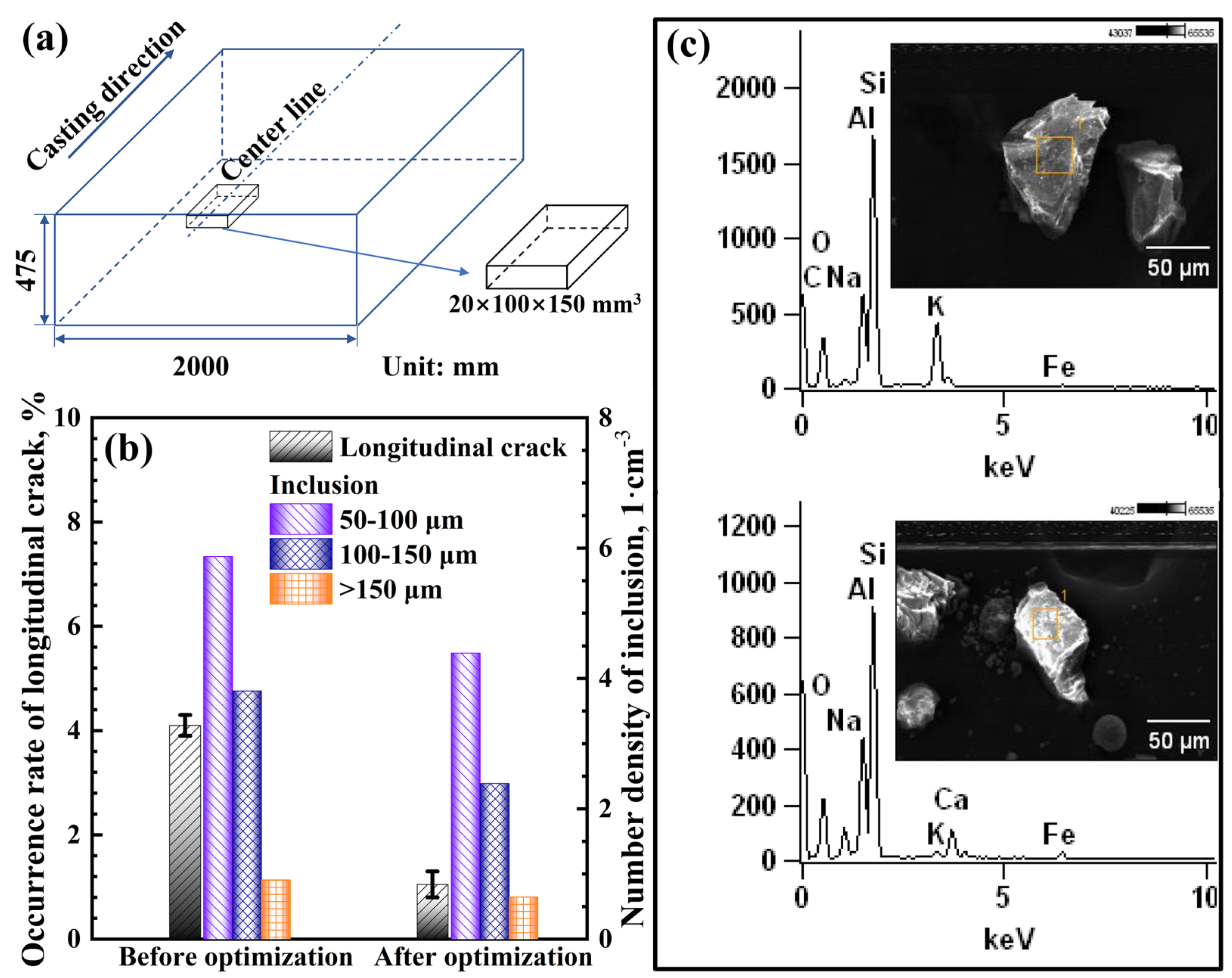
3.4. Field Production

As analyzed above, a square-shaped-port SEN with a downward angle of −10° is more beneficial for ultra-thick slab CC by comprehensive consideration. The optimized SEN has been applied to the actual caster considered in the current work. To assess the practical performance of the optimization on the SEN, the occurrence of surface longitudinal cracks on (hypo-)peritectic steels has been counted for six months before and after the optimization. Moreover, steel samples from the plant have been obtained and machined as shown in Figure 12a. Inclusions in the obtained samples have been quantitatively extracted by the method of galvanostatic electrolysis [40]. As shown in Figure 12b, the occurrence of longitudinal cracks and the inclusion content of the ultra-thick slabs have been reduced after the SEN optimization. Moreover, some inclusions originating from slag entrainment in the mold, shown in Figure 12c, have been detected in the sample obtained before optimization. This type of inclusion can hardly be detected in the optimization sample.

4. Conclusions

A mathematical model has been established for an ultra-thick slab CC mold. The molten steel flow and solidification, inclusion transports, and meniscus fluctuation have also been investigated through the developed model. Based on the results of the computations, the SEN for the ultra-thick slab mold has been optimized. The conclusions are as follows:
  • Compared with the case with a concave-bottom SEN, the convex-bottom SEN decreases the downward angle of the imping jet and imping depth, and increases the horizontal velocity and temperature on the meniscus. The molten steel velocity near the solidified shell for the convex-bottom case is larger than those for the cases with concave bottoms. However, the remelting of the solidified shell is dramatic for the convex-bottom case. The well depth of the concave-bottom SEN has little influence on the molten steel flow pattern and solidification.
  • The effect of the SEN port shape on the molten steel flow is significant. As the port shape changes from rectangle to square, the angle of jet flow and imping depth decrease. The horizontal velocity and the temperature on the mold free surface increase. The SEN with a square port is beneficial for molten steel solidification and inclusion removal.
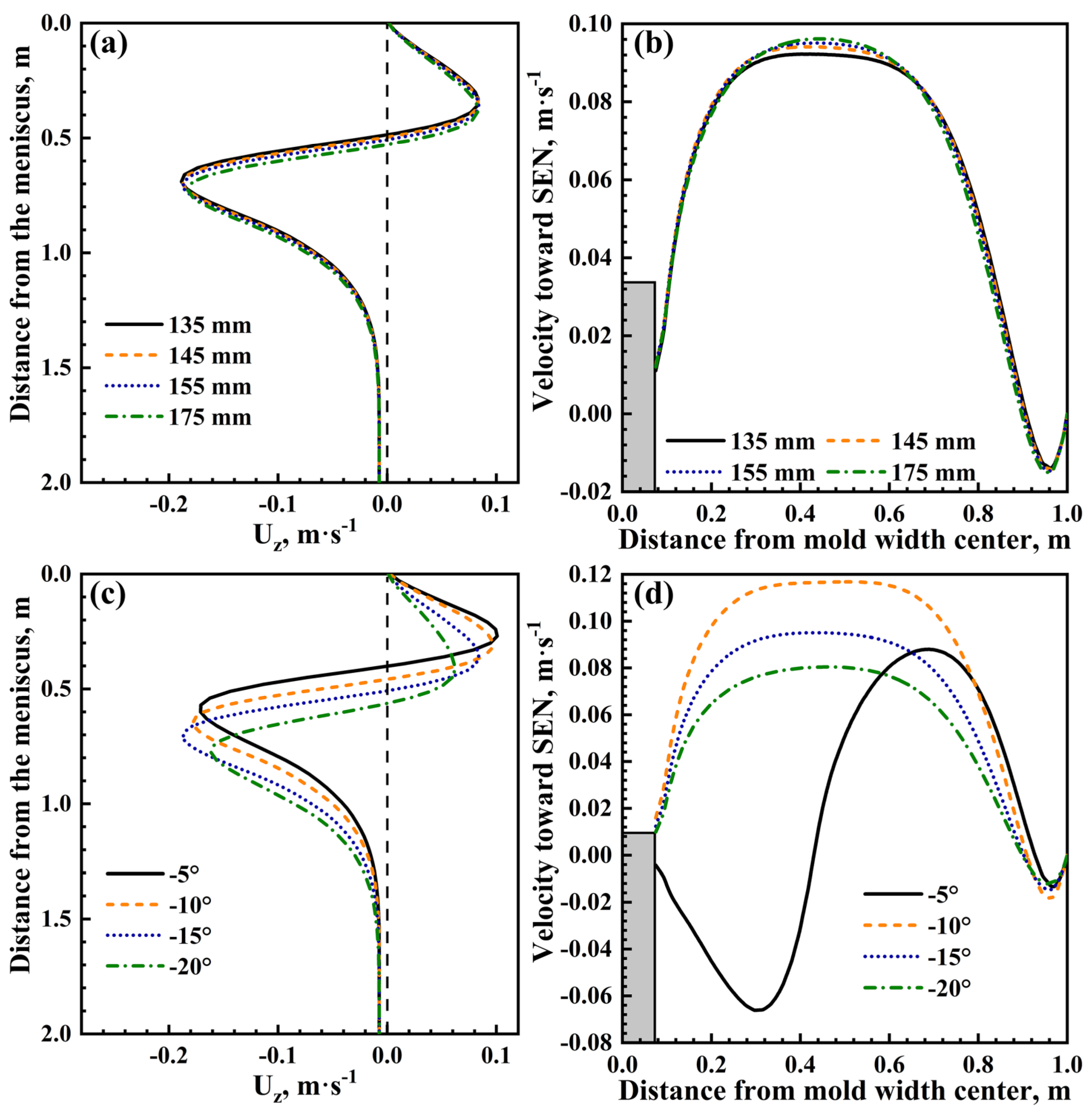
  • The SEN’s submerged depth has a tiny impact on the molten steel flow. Nevertheless, the SEN port angle has a significant influence on the molten steel flow. As the downward angle of the port increases, the imping depth of molten steel jet flow obviously increases, and the flow in the URZ changes to be gradually weakened.
  • A square-shaped-port SEN with a downward angle of −10° is more beneficial for ultra-thick slab CC by comprehensive consideration of molten steel flow and solidification and inclusion removal. The optimized SEN has been applied to the actual caster, and the practical performance of the optimization has been assessed, indicating that the SEN optimization is efficient.

Author Contributions

Y.Y. and J.Z. conceived and designed the study; Y.Y. performed the numerical calculation; Y.Y. and P.X. conducted the experiment; Y.Y. wrote the paper. All authors have read and agreed to the published version of the manuscript.

Funding

This research was funded by the National Natural Science Foundation of China (Nos. 52104320, 51834002 and 51904107) and Postdoctoral Research Foundation of China (No. 2021M690371).

Data Availability Statement

The data presented in this study are available on request from the corresponding author. The data are not publicly available due to privacy restrictions.

Acknowledgments

This work was supported by the National Natural Science Foundation of China (Nos. 52104320, 51834002 and 51904107) and Postdoctoral Research Foundation of China (No. 2021M690371). The authors are grateful for their financial support.

Conflicts of Interest

The authors declare no conflict of interest.

References

  1. Jiang, M.; Yang, E.; Hou, Z.; Wang, X. Decreasing Porosities in Continuous Casting Thick Slab by Soft Reduction Technology. Metall. Mater. Trans. B 2021, 52, 2753–2759. [Google Scholar] [CrossRef]
  2. Schwinn, V.; Bauer, J.; Flüss, P.; Kirsch, H.J.; Amoris, E. Recent Developments and Applications of TMCP Steel Plates. Metall. Res. Technol. 2011, 108, 283–294. [Google Scholar] [CrossRef] [Green Version]
  3. Yu, W.; Zhang, Y.; He, C.; Xu, L.; Cai, Q. Production of Heavy-gauge Steel Plates by Clad Rolling Process. J. Univ. Sci. Technol. Beijing 2011, 33, 1391–1395. [Google Scholar] [CrossRef]
  4. Jiang, M.; Yao, T.; Yang, E.; Wang, X. Decreasing Central Porosities in a Continuous Casting Thick Slab by Heavy Mechanical Reduction Near the Solidification End. Metall. Mater. Trans. B 2022, 53, 3322–3333. [Google Scholar] [CrossRef]
  5. Zhao, X.; Zhang, J.; Lei, S.; Wang, Y. Dynamic Recrystallization (DRX) Analysis of Heavy Reduction Process with Extra-Thickness Slabs. Steel Res. Int. 2014, 85, 811–823. [Google Scholar] [CrossRef]
  6. Kunstreich, S. Strand Electromagnetic Stirring for Thick Slab Casters. Metall. Plant Technol. Int. 2006, 29, 50–52. [Google Scholar]
  7. Zhou, Q.; Yin, Y.; Zhang, J. Numerical Simulation Research and Application of Convex Roll for Efficient Soft Reduction of Continuous Casting Slab. Metall. Mater. Trans. B 2022, 53, 4029–4047. [Google Scholar] [CrossRef]
  8. Zhao, X.; Zhang, J.; Lei, S.; Wang, Y. The Position Study of Heavy Reduction Process for Improving Centerline Segregation or Porosity with Extra- Thickness Slabs. Steel Res. Int. 2014, 85, 645–658. [Google Scholar] [CrossRef]
  9. Wu, C.; Ji, C.; Zhu, M. Deformation Behavior of Internal Porosity in Continuous Casting Wide-Thick Slab during Heavy Reduction. Metals 2019, 9, 128. [Google Scholar] [CrossRef] [Green Version]
  10. Shen, J.; Chen, D.; Xie, X.; Zhang, L.; Dong, Z.; Long, M.; Ruan, X. Influences of SEN Structures on Flow Characters, Temperature Field and Shell Distribution in 420 mm Continuous Casting Mould. Ironmak. Steelmak. 2013, 40, 263–275. [Google Scholar] [CrossRef]
  11. Li, X.; Liu, Y.; Zhang, H.; Guobiao, D.; Ji, C.; Li, H.; Liu, J.; Zhang, M. Formation and Control of Longitudinal Cracks in Hypoperitectic Steel Slabs. Ironmak. Steelmak. 2022, 1–5. [Google Scholar] [CrossRef]
  12. Cho, S.; Thomas, B.G. Electromagnetic Effects on Solidification Defect Formation in Continuous Steel Casting. JOM 2020, 72, 3610–3627. [Google Scholar] [CrossRef]
  13. Cai, Z.; Zhu, M. Non-uniform Heat Transfer Behavior during Shell Solidification in a Wide and Thick Slab Continuous Casting Mold. Int. J. Miner. Metall. Mater. 2014, 21, 240–250. [Google Scholar] [CrossRef]
  14. Ji, C.; Luo, S.; Zhu, M.; Sahai, Y. Uneven Solidification during Wide-thick Slab Continuous Casting Process and its Influence on Soft Reduction Zone. ISIJ Int. 2014, 54, 103–111. [Google Scholar] [CrossRef] [Green Version]
  15. Lachmund, H.; Schwinn, V.; Jungblut, H.A. Heavy Plate Production: Demand on Hydrogen Control. Ironmak. Steelmak. 2000, 27, 381–386. [Google Scholar] [CrossRef]
  16. Gupta, D.; Lahiri, A.K. Water Modelling Study of the Jet Characteristics in a Continuous Casting Mould. Steel Res. 1992, 63, 201–204. [Google Scholar] [CrossRef]
  17. Deng, X.; Xiong, X.; Wang, X.; Ji, Y.; Huang, F.; Hao, X. Water Modeling Study on Submerged Entry Nozzles in Continuous Slab Casting Molds for High Speed Casting. J. Univ. Sci. Technol. Beijing 2013, 35, 1304–1312. [Google Scholar] [CrossRef]
  18. Fang, Q.; Ni, H.; Zhang, H.; Wang, B.; Lv, Z. The Effects of a Submerged Entry Nozzle on Flow and Initial Solidification in a Continuous Casting Bloom Mold with Electromagnetic Stirring. Metals 2017, 7, 146. [Google Scholar] [CrossRef] [Green Version]
  19. Salazar-Campoy, M.M.; Morales, R.D.; Nájera-Bastida, A.; Calderón-Ramos, I.; Cedillo-Hernández, V.; Delgado-Pureco, J.C. A Physical Model to Study the Effects of Nozzle Design on Dispersed Two-Phase Flows in a Slab Mold Casting Ultra-Low-Carbon Steels. Metall. Mater. Trans. B 2018, 49, 812–830. [Google Scholar] [CrossRef]
  20. Calderón-Ramos, I.; Morales, R.D.; Servín-Castañeda, R.; Pérez-Alvarado, A.; García-Hernández, S.; Barreto, J.d.J.; Arreola-Villa, S.A. Modeling Study of Turbulent Flow in a Continuous Casting Slab Mold Comparing Three Ports SEN Designs. ISIJ Int. 2019, 59, 76–85. [Google Scholar] [CrossRef] [Green Version]
  21. Saldaña-Salas, F.; Torres-Alonso, E.; Ramos-Banderas, J.A.; Solorio-Díaz, G.; Hernández-Bocanegra, C.A. Analysis of the Depth of Immersion of the Submerged Entry Nozzle on the Oscillations of the Meniscus in a Continuous Casting Mold. Metals 2019, 9, 596. [Google Scholar] [CrossRef] [Green Version]
  22. Gonzalez-Trejo, J.; Miranda-Tello, J.R.; Cervantes-de-la-Torre, F.; Carvajal-Mariscal, I.; Sanchez-Silva, F.; Gabbasov, R.; Real-Ramirez, C.A. Experimental Analysis of a Slab Continuous-Casting SEN with an Inner Flow Divider. Metals 2022, 12, 1097. [Google Scholar] [CrossRef]
  23. Liu, Q.; Du, Y.; Xu, P.; Chen, D.; Long, M. Optimization of Nozzle Parameters by Investigating the Flow Behavior of Molten Steel in the Mold under a High Casting Speed. Metals 2022, 12, 1595. [Google Scholar] [CrossRef]
  24. Wang, P.; Tie, Z.; Xiao, H.; Zhu, J.; Tang, H.; Zhang, J. Optimizing of Submerged Entry Nozzle for Bloom Continuous Casting Based on Physical and Numerical Simulation. Steel Res. Int. 2022, 93, 2200402. [Google Scholar] [CrossRef]
  25. Liu, R.; Blazek, K.; Forman, B.; Fritz, C.; Graham, C. Effect of Submerged-Entry Nozzle (SEN) Design on Fluid Flow and Heat Transfer in a Thin-Slab Steel Caster. Steel Res. Int. 2019, 90, 1800398. [Google Scholar] [CrossRef]
  26. Morales, R.D.; Palafox-Ramos, J.; Garcia-Demedices, L.; Sanchez-Perez, R. A DPIV Study of Liquid Steel Flow in a Wide Thin Slab Caster Using Four Ports Submerged Entry Nozzles. ISIJ Int. 2004, 44, 1384–1392. [Google Scholar] [CrossRef] [Green Version]
  27. Tsukaguchi, Y.; Hayashi, H.; Kurimoto, H.; Yokoya, S.; Marukawa, K.; Tanaka, T. Development of Swirling-flow Submerged Entry Nozzles for Slab Casting. ISIJ Int. 2010, 50, 721–729. [Google Scholar] [CrossRef] [Green Version]
  28. Chen, J.; Su, Z.; Li, D.; Wang, Q.; He, J. Flow Behavior in the Slab Mold under Optimized Swirling Technology in Submerged Entry Nozzle. ISIJ Int. 2018, 58, 1242–1249. [Google Scholar] [CrossRef] [Green Version]
  29. Wu, D.F.; Cheng, S.S. Effect of Sen Design on Surface Fluctuation and Solidifying Shell in Slab Mold and Its Optimization. Acta Metall. Sin. (Engl. Lett.) 2008, 21, 341–350. [Google Scholar] [CrossRef]
  30. Bai, H.; Thomas, B.G. Turbulent flow of liquid steel and argon bubbles in slide-gate tundish nozzles: Part II. Effect of operation conditions and nozzle design. Metall. Mater. Trans. B 2001, 32, 269–284. [Google Scholar] [CrossRef]
  31. Garcia-hernandez, S.; Morales, R.D.; Barreto, J.d.J.; Morales-higa, K. Numerical Optimization of Nozzle Ports to Improve the Fluidynamics by Controlling Backflow in a Continuous Casting Slab Mold. ISIJ Int. 2013, 53, 1794–1802. [Google Scholar] [CrossRef] [Green Version]
  32. Sun, H.; Li, L.; Liu, C. Novel Opposite Stirring Mode in Bloom Continuous Casting Mould by Combining Swirling Flow Nozzle with EMS. Metals 2018, 8, 842. [Google Scholar] [CrossRef] [Green Version]
  33. Gan, M.; Pan, W.; Wang, Q.; Zhang, X.; He, S. Effect of Exit Shape of Submerged Entry Nozzle on Flow Field and Slag Entrainment in Continuous Casting Mold. Metall. Mater. Trans. B 2020, 51, 2862–2870. [Google Scholar] [CrossRef]
  34. Arcos-Gutierrez, H.; Barrera-Cardiel, G.; Barreto, J.d.J.; Garcia-Hernandez, S. Numerical Study of Internal SEN Design Effects on Jet Oscillations in a Funnel Thin Slab Caster. ISIJ Int. 2014, 54, 1304–1313. [Google Scholar] [CrossRef] [Green Version]
  35. Aboutalebi, M.M.; Lapointe, F.; D’amours, J.; Isac, M.M.; Guthrie, R.I.L. Effects of Angle of Rotation of Submerged Entry Nozzle on Fluid Flows in a Square Billet Casting Mold. JOM 2018, 70, 2088–2095. [Google Scholar] [CrossRef] [Green Version]
  36. Li, L.; Wang, X.; Deng, X.; Wang, X.; Qin, Y.; Ji, C. Application of High Speed Continuous Casting on Low Carbon Conventional Slab in SGJT. Steel Res. Int. 2014, 85, 1490–1500. [Google Scholar] [CrossRef]
  37. Miranda, R.; Barron, M.A.; Barreto, J.; Hoyos, L.; Gonzalez, J. Experimental and Numerical Analysis of the Free Surface in a Water Model of a Slab Continuous Casting Mold. ISIJ Int. 2005, 45, 1626–1635. [Google Scholar] [CrossRef] [Green Version]
  38. Gonzalez-Trejo, J.; Gabbasov, R.; Miranda-Tello, J.R.; Carvajal-Mariscal, I.; Cervantes-de-la-Torre, F.; Sanchez-Silva, F.; Real-Ramirez, C.A. Analysis of a New SEN Design with an Inner Flow Divider. Metals 2021, 11, 1437. [Google Scholar] [CrossRef]
  39. Yin, Y.; Zhang, J.; Dong, Q.; Zhou, Q. Mathematical modelling of inclusion motion and entrapment in billet mould with effect of electromagnetic stirring. Ironmak. Steelmak. 2019, 46, 855–864. [Google Scholar] [CrossRef]
  40. Yin, Y.; Zhang, J.; Lei, S.; Dong, Q. Numerical Study on the Capture of Large Inclusion in Slab Continuous Casting with the Effect of In-mold Electromagnetic Stirring. ISIJ Int. 2017, 57, 2165–2174. [Google Scholar] [CrossRef] [Green Version]
  41. Launder, B.E.; Spalding, D.B. The Numerical Computation of Turbulent Flows. Comput. Methods Appl. Mech. Eng. 1974, 3, 269–289. [Google Scholar] [CrossRef]
  42. Brent, A.D.; Voller, V.R.; Reid, K.J. Enthalpy-porosity technique for modeling convection-diffusion phase change: Application to the melting of a pure metal. Numer. Heat Transf. A Appl. 1988, 13, 297–318. [Google Scholar] [CrossRef]
  43. Trindade, L.B.; Nadalon, J.E.A.; Contini, A.C.; Barroso, R.C. Modeling of Solidification in Continuous Casting Round Billet with Mold Electromagnetic Stirring (M-EMS). Steel Res. Int. 2017, 88, 1600319. [Google Scholar] [CrossRef]
  44. Liu, Z.; Li, B.; Zhang, L.; Xu, G. Analysis of Transient Transport and Entrapment of Particle in Continuous Casting Mold. ISIJ Int. 2014, 54, 2324–2333. [Google Scholar] [CrossRef] [Green Version]
  45. Liu, H.; Yang, C.; Zhang, H.; Zhai, Q.; Gan, Y. Numerical Simulation of Fluid Flow and Thermal Characteristics of Thin Slab in the Funnel-Type Molds of Two Casters. ISIJ Int. 2011, 51, 392–401. [Google Scholar] [CrossRef] [Green Version]
  46. Dong, Q.; Zhang, J.; Yin, Y.; Wang, B. Three-Dimensional Numerical Modeling of Macrosegregation in Continuously Cast Billets. Metals 2017, 7, 209. [Google Scholar] [CrossRef] [Green Version]
  47. Yin, Y.; Zhang, J.; Ma, H.; Zhou, Q. Large Eddy Simulation of Transient Flow, Particle Transport, and Entrapment in Slab Mold with Double-Ruler Electromagnetic Braking. Steel Res. Int. 2021, 92, 2000582. [Google Scholar] [CrossRef]
  48. Li, Z.; Wang, E.; Zhang, L.; Xu, Y.; Deng, A. Influence of Vertical Electromagnetic Brake on the Steel/Slag Interface Behavior in a Slab Mold. Metall. Mater. Trans. B 2017, 48, 2389–2402. [Google Scholar] [CrossRef]
  49. Zhang, L.; Yang, S.; Cai, K.; Li, J.; Wan, X.; Thomas, B.G. Investigation of fluid flow and steel cleanliness in the continuous casting strand. Metall. Mater. Trans. B 2007, 38, 63–83. [Google Scholar] [CrossRef]
  50. Yuan, Q.; Thomas, B.G.; Vanka, S.P. Study of transient flow and particle transport in continuous steel caster molds: Part I. Fluid flow. Metall. Mater. Trans. B 2004, 35, 685–702. [Google Scholar] [CrossRef] [Green Version]
  51. Thomas, B.G.; Jenkins, M.S.; Mahapatra, R.B. Investigation of Strand Surface Defects Using Mould Instrumentation and Modelling. Ironmak. Steelmak. 2004, 31, 485–494. [Google Scholar] [CrossRef]
Figure 1. Schematic diagrams for geometry model and mesh used in the calculation: (a) the whole geome-try and mesh and (b) SEN structures.
Metals 13 00221 g001
Figure 2. The variation of solidified shell thickness in mold along the casting direction.
Metals 13 00221 g002
Figure 3. Streamline and contour plot of steel liquid fraction on the mid-thickness plane of the mold with different SEN bottoms and port shapes.
Metals 13 00221 g003
Figure 4. Longitudinal velocity profiles near NF solidification front along the casting direction (a,c) and horizontal velocity variations on the meniscus (b,d) with different SEN bottoms and port shapes.
Metals 13 00221 g004
Figure 5. Temperature distributions on the meniscus under different conditions of SEN bottoms and port shapes.
Metals 13 00221 g005
Figure 6. Solidified shell distributions along the casting direction (a,c) and the predicted inclusion ratios of removal and escape (b,d) with different SEN bottoms and port shapes.
Metals 13 00221 g006
Figure 7. The calculated 3D meniscus level profile for the concave-bottom case with 27.5 mm well depth (a) and meniscus level profiles on the mid-thickness plane of the mold under different conditions (b,c).
Metals 13 00221 g007
Figure 8. Longitudinal velocity profiles near NF solidification front along the casting direction (a,c) and horizontal velocity variations on the meniscus (b,d) with different SEN submerged depths and port angles.
Metals 13 00221 g008
Figure 9. Effect of SEN port angle on molten steel flow in the mold and temperature distribution on the meniscus.
Metals 13 00221 g009
Figure 10. Solidified shell distributions along the casting direction (a) and the predicted inclusion ratios of removal and escape (b) with different SEN port angles.
Metals 13 00221 g010
Figure 11. The calculated 3D meniscus level profiles for the cases with −5° (a) and −10° (b) port angles; and meniscus level profiles on the mid-thickness plane of the mold under different port angles (c).
Metals 13 00221 g011
Figure 12. Schematic diagram of samples used for galvanostatic electrolysis (a); longitudinal crack occurrence rate and large inclusion content before and after optimization (b); and inclusions originated from slag entrainment in mold (c).
Metals 13 00221 g012
Table 1. The physical parameters and model parameters.
ParametersValuesDimensions
Specific heat650J·kg−1·K−1
Thermal conductivity31W·m−1·K−1
Molten steel molecular viscosity0.0055kg·s−1·m−1
Molten steel density7020kg·m−3
Steel latent heat268,000J·kg−1
Liquid temperature1766K
Solid temperature1718K
Inclusion density2700kg·m−3
Inclusion diameter10μm
Mold section0.475 × 2m2
SEN inner diameter0.085m
SEN outer diameter0.15m
Pouring temperature1786K
Casting speed0.45m·min−1
Table 2. The boundary conditions used for the flow and heat transfer computations.
Boundary Conditions u pk, εT
InletfixedValuezeroGradientfixedValuefixedValue, 1786 K
MeniscusslipzeroGradientWFzeroGradient
SEN wallsnoSlipzeroGradientWFzeroGradient
Symmetry planessymmetrysymmetrysymmetrysymmetry
Mold, BFfixedValuezeroGradientWF q = 2,680,000 + 233,691 t
Mold, NFfixedValuezeroGradientWF q = 2,680,000 + 225,567 t
FRZ, BFfixedValuezeroGradientWF q = 1022 × ( T T w )
FRZ, NFfixedValuezeroGradientWF q = 1207 × ( T T w )
SCZfixedValuezeroGradientWF q = 550 × ( T T w )
OutletzeroGradientfixedValuezeroGradientzeroGradient
Disclaimer/Publisher’s Note: The statements, opinions and data contained in all publications are solely those of the individual author(s) and contributor(s) and not of MDPI and/or the editor(s). MDPI and/or the editor(s) disclaim responsibility for any injury to people or property resulting from any ideas, methods, instructions or products referred to in the content.

