Article

Microstructure and Mechanical Properties of LaB6/Ti-6Al-4V Composites Fabricated by Selective Laser Melting

1
Fujian Key Laboratory of Intelligent Machining Technology and Equipment, Fuzhou 350118, China
2
School of Mechanical and Automotive Engineering, Fujian University of Technology, Fuzhou 350118, China
*
Author to whom correspondence should be addressed.
Metals 2023, 13(2), 264; https://doi.org/10.3390/met13020264
Submission received: 28 November 2022 / Revised: 24 January 2023 / Accepted: 25 January 2023 / Published: 29 January 2023

Abstract

:
In this study, TiB + La2O3/Ti-6Al-4V composites were successfully prepared by in situ reaction using selective laser melting technology. The effect of LaB6 content on the fabrication quality, microstructure evolution and mechanical properties of the composite samples was investigated. The results show that the relative density of the sample gradually decreased from 98.56% to 96.57% as LaB6 content increased from 0 wt% to 3 wt%. With increasing LaB6 content, TiB precipitates gradually aggregated and grew from a discrete needle-like structure to a dendritic structure, before eventually developing a cell-like structure. The dislocations piled up around the TiB and La2O3 reinforcements, which impeded the motion of the dislocations and led to the enhancement of the tensile strength of the samples. Different from the addition of a single reinforcement due to the combined strengthening effect of the micrometer-scale and nanoscale reinforcements, the strength of the samples was increased significantly. The Ti-6Al-4V sample with 3 wt% LaB6 addition showed the most significant strengthening effect. Compared to the pure Ti-6Al-4V sample, the 3 wt% LaB6 addition sample gained a 35.71% increase in hardness and a 14.5% increase in tensile strength. Additionally, wear volume was reduced by 47.5%. The results revealed that the addition of LaB6 was a potential way to improve the mechanical performance of the titanium alloys in the additive manufacturing process.

1. Introduction

Compared to pure titanium alloys, titanium-based composites have higher strength and wear resistance, as well as better high-temperature creep and fatigue properties, and are widely used in aerospace, automotive, biomedical and other industries [1,2]. Rare earth oxides such as TiB, TiC, TiN, Al2O3, SiC, graphite and La2O3 are often used as reinforcing materials for titanium alloys [3,4,5]. Among them, TiB has similar densities, similar Poisson’s ratios, good compatibility, and no interfacial reactions with Ti. Some rare earth elements such as La easily react with oxygen, with this specific element thus forming La2O3, which improves the oxidation resistance and thermal stability of titanium alloys [6,7,8].
The mechanical properties of metals can be adjusted by adding rare earth oxides. Li et al. [9] prepared TiB + La2O3-reinforced titanium matrix composites by vacuum electric arc furnace in situ synthesis and adjusted the heat treatment process to increase the elongation of the composites by 126% at 293 K. Han et al. [10] prepared new high-performance layered (TiB + La2O3)/Ti composites through a combination of powder metallurgy and hot rolling. The size and composition of the reinforcement was controlled by in situ reaction of Ti and LaB6 at high temperatures. Yi et al. [11] synthesized (TiB + La2O3)/Ti-Ni composites in situ via vacuum sintering, and high strength and better strain recovery properties could be obtained by adjusting the network structure. Sun et al. [12] found that both micron-scale TiB and sub-micron La2O3 can hinder dislocation motion, and TiB can promote the recrystallization of the matrix phase and grain refinement. According to the literature, TiB and La2O3 may have a synergistic enhancement effect for titanium alloys.
Selective laser melting (SLM) can directly process stacked powders into near net shape products without the constraints of product shape structure and is one of the most rapidly developing additive manufacturing technologies [13,14,15]. In recent years, the use of SLM techniques to prepare novel titanium matrix composites has been the focus of research for many scholars. The effect of the mass fraction of the particle-reinforced phase on the microstructure, hardness, wear resistance, strength and plasticity of the composite has been previously investigated. For example, Gu et al. [16] added different masses of TiC to titanium alloy and found that, when the content of TiC was 7.5 wt% and 12.5 wt%, the density of the sample structure was relatively uniform, and excessive content would lead to the agglomeration of TiC particles and reduce density. Another focus is to investigate the parameters of the SLM process. Krakhmalev et al. [17] added SiC-reinforced particles to titanium alloy to study the relationship between the energy density and the induced density of the sample and found that an increase in energy density in a certain range would lead to a decrease in induced density. Cai et al. [18] reported the results of the TiB strengthening of Ti-6Al-4V. The hardness of the composite samples increased gradually with the increase in TiB content, and the wear resistance was also better. Xia et al. [19] studied the relationship between laser power and the surface accuracy of (TiB + TiC)-enhanced titanium matrix composite samples and found that TiB whiskers and TiC phases tended to grow and coarsen with the increase in laser power. There are still many challenges in the study of particle-reinforced titanium matrix composites fabricated via SLM, including the issue of defects such as pores and cracks that are caused by the addition of ceramic particles.
Previous studies on Ti-6Al-4V-based composites have focused on traditional processing methods such as powder metallurgy, where the reinforcements were added directly into the powders. In this study, TiB + La2O3/Ti-6Al-4V composites were prepared by SLM through in situ reaction between LaB6 and Ti-6Al-4V for the first time. LaB6 content was also adjusted to obtain the best mechanical performance. The effect of LaB6 content on the strengthening mechanism of the composites was discussed. It provides a basis for studying the composition design of the titanium-based alloys.

2. Experiments and Methods

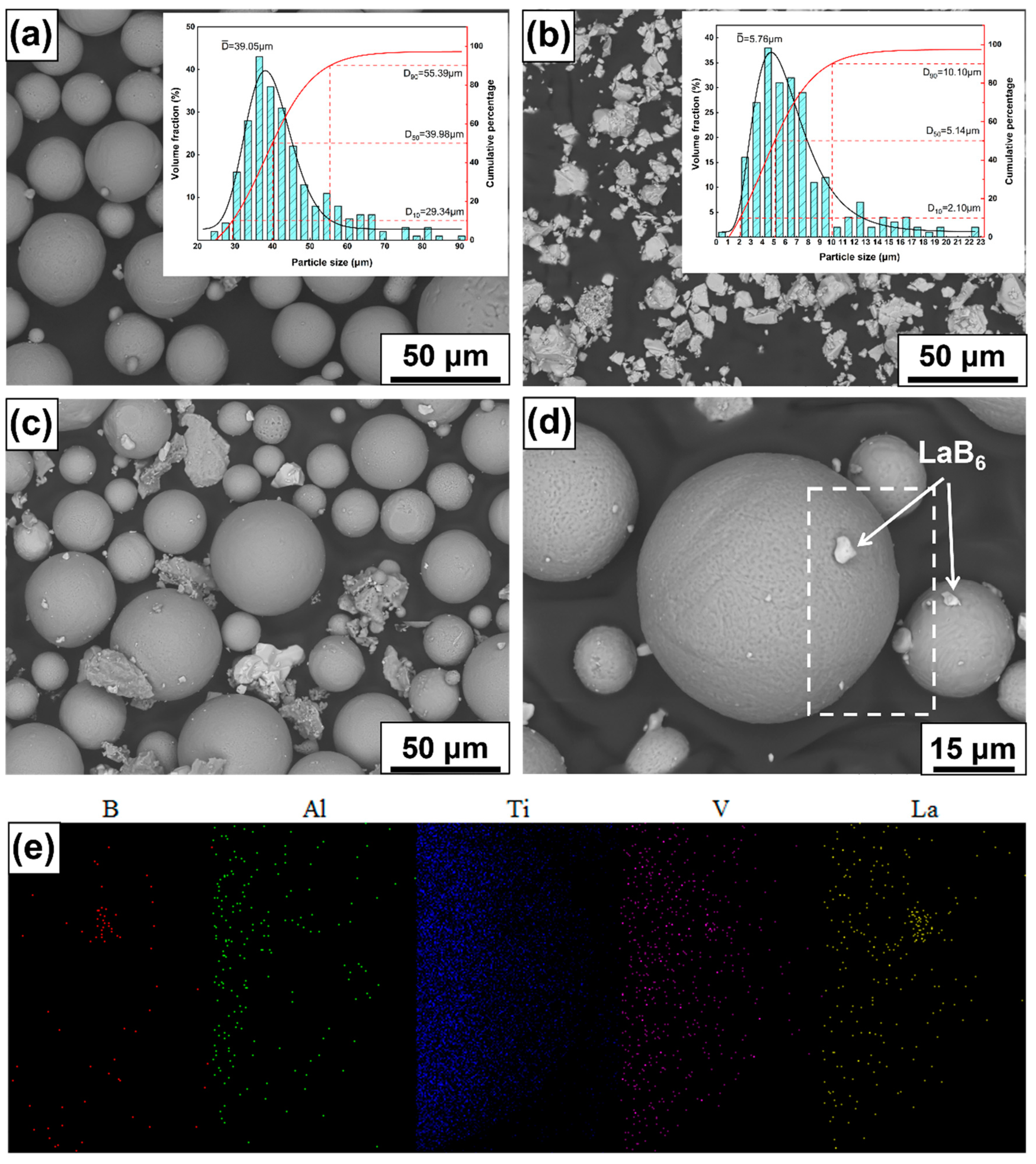
2.1. Powder Preparation

In this paper, a commercial Ti-6Al-4V powder provided by Guorui Zhongke Optoelectronics Co., Ltd. (Fuzhou, China) was used. As shown in Figure 1a, the powder is nearly spherical. Powder size was measured by Nano Measure software. Table 1 shows the chemical composition of the Ti-6Al-4V powders. Particle sizes ranged from 9 to 52 μm, and the average diameter was 31.9 μm. As shown in Figure 1b, LaB6 was a polyhedral granular powder with a particle size ranging between 1 and 21 μm, with an average particle size of 7.4 μm. LaB6 was provided by Aladdin Biochemical Technology Co., Ltd. (Shanghai, China). Ti-6Al-4V was mixed with four different concentrations of LaB6, i.e., 0 wt%, 0.5 wt%, 1 wt% and 3 wt%. The mixture was obtained via ball milling using a Miqi planetary ball mill was provided by Nanjing Chishun Technology Development Co., Ltd. (Changsha, China). The agate ball to powder ratio was 4:1 by weight. The rotation speed was 300 r/min, and the ball milling time was 4 h. To avoid high temperatures during ball milling, the material was cooled for 10 min every half hour. The mixed powders were observed and analyzed using an FEI NovaNanoSEM450 field emission scanning electron microscope (FEI Company, Hillsboro, OR, USA), and energy-dispersive X-ray spectroscopy (EDS), (FEI Company, Hillsboro, OR, USA), as shown in Figure 1c, Figure 1d and Figure 1e. After ball milling, Ti-6Al-4V powder still appeared to have a nearly spherical shape, and fine LaB6 particles were attached to the Ti-6Al-4V powder.

2.2. SLM Process

In this paper, an SLM Solutions 125HL was used to fabricate the Ti-6Al-4V samples. The fabricating bin space was 125 mm × 125 mm × 125 mm, the machine was equipped with a 400WIPG fiber laser (SLM Solutions, Lübeck, Germany), and the spot diameter was 70 μm. Laser power was 330 W, scanning speed was 300 mm/s, powder thickness was set to 30 μm, the scanning rotation angle was 67° between the upper layer and the lower layer and scanning distance was set to 0.12 mm. Ti-6Al-4V samples with different TiB6 content were printed. A schematic diagram of the melting pool is shown in Figure 2. In order to prevent the powder from being moistened, the composite powder was dried at 100 °C for 5 h using a vacuum drying oven. The substrate was sandblasted to ensure the strength of the bonding between the sample and the substrate. Argon was used as a protective gas during printing, and oxygen content was always kept below 0.1% to avoid oxidation of the sample. Subsequently, 10 mm × 10 mm × 10 mm cubic samples and ASTEME8-0 standard tensile parts were fabricated. The Ti-6Al-4V samples with 0, 0.5, 1 and 3 wt% TiB6 content are referred to as S0, S05, S1 and S3, respectively.

2.3. Microstructure Characterization and Analysis

The laser absorptivity of Ti-6Al-4V powders with different LaB6 content was determined by diffuse reflectance spectroscopy (DRS). UV-VIS-NIR (Japan-Shimadzu-UV-3600 plus, Shimadzu, Kyoto, Japan) was used to measure DRS, and the spectrophotometer was equipped with an integrating sphere with a diameter of 150 mm which was used to measure laser absorptivity in the wavelength range of 200–2000 nm.
The surface of the cubic samples was then ground and polished. The phase was determined and analyzed using the German Bruker D8ADVANCE X-ray diffractometer, (Bruker, Billerica, MA, USA), CuKα (λ = 1.5418 Å, working current 40 mA, working voltage 40 kV). The step size was 0.02° and the samples were scanned in the range of 2θ = 20–80°, with a scanning speed of 6 °/min. The metallographic experiments were conducted according to the ASTM E340-00el standard. During metallurgical sampling, 100#, 400#, 800#, 1200#, 1500#, 2000# and 3000# metallurgical sandpapers were used to manually polish the surfaces of the samples. The macroscopic morphology of the sample surfaces was observed with a KH1300 stereo microscope and the surface was observed with an FEI NanoSEM450 field emission scanning electron microscope equipped with an EDS (HV = 18.00 KV, WD = 8.9 mm). TEM samples with a diameter of 3 mm were prepared using a Gatan 656 high-precision crater and an ion thinning instrument (Pleasanton, CA, USA). The microstructures of the samples were observed using an FEI TECNAI G2 F20 electron microscope system, (FEI Company, Hillsboro, OR, USA) (HV = 18.00KV).

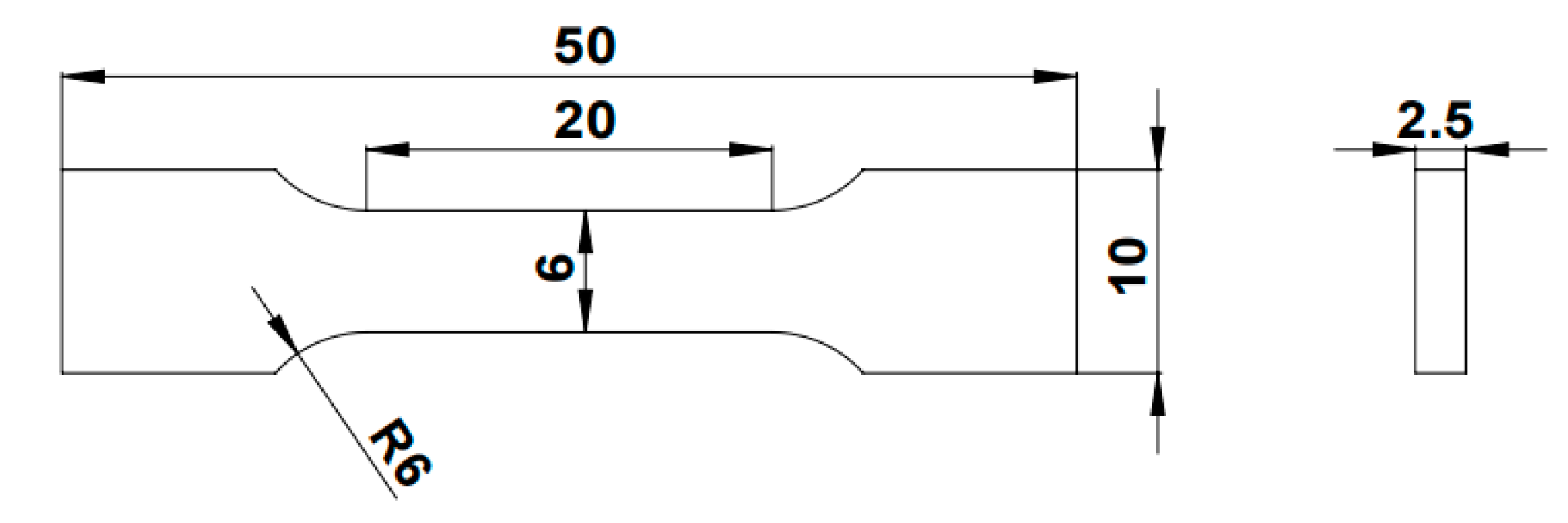
2.4. Mechanical Property Test

The hardness of the polished samples was measured at a pressure of 500 g for 15 s using the MVA-402TS hardness tester (Shenzhen Irma Electromechanical Equipment Co Ltd. Shenzhen, China) (Practice AS FM E92-82(2003)). The test involves selecting nine equally spaced locations on the surface of each sample in the same direction, with the average hardness of these locations referred to as the Vickers hardness value of the sample. Using the UMT-Tribolab high-load scratch tester, friction and abrasion experiments were performed on the polished samples under the following experimental conditions: pressure, 3 N; abrasion time, 30 min; abrasion distance, 3 mm. The coefficient of friction (COF) and the wear volume of samples with different content were measured. An INSTRON 2382 electronic universal test machine from the United States was used for tensile testing, with a tensile speed of 0.4 mm/min (Practice ASTM E8-01e1). Nine tensile samples were prepared for each concentration and the mean value was taken as the final result. The dimensions of the standard stretched part of the ASTEME8-0 test specimen are shown in Figure 3.

3. Results

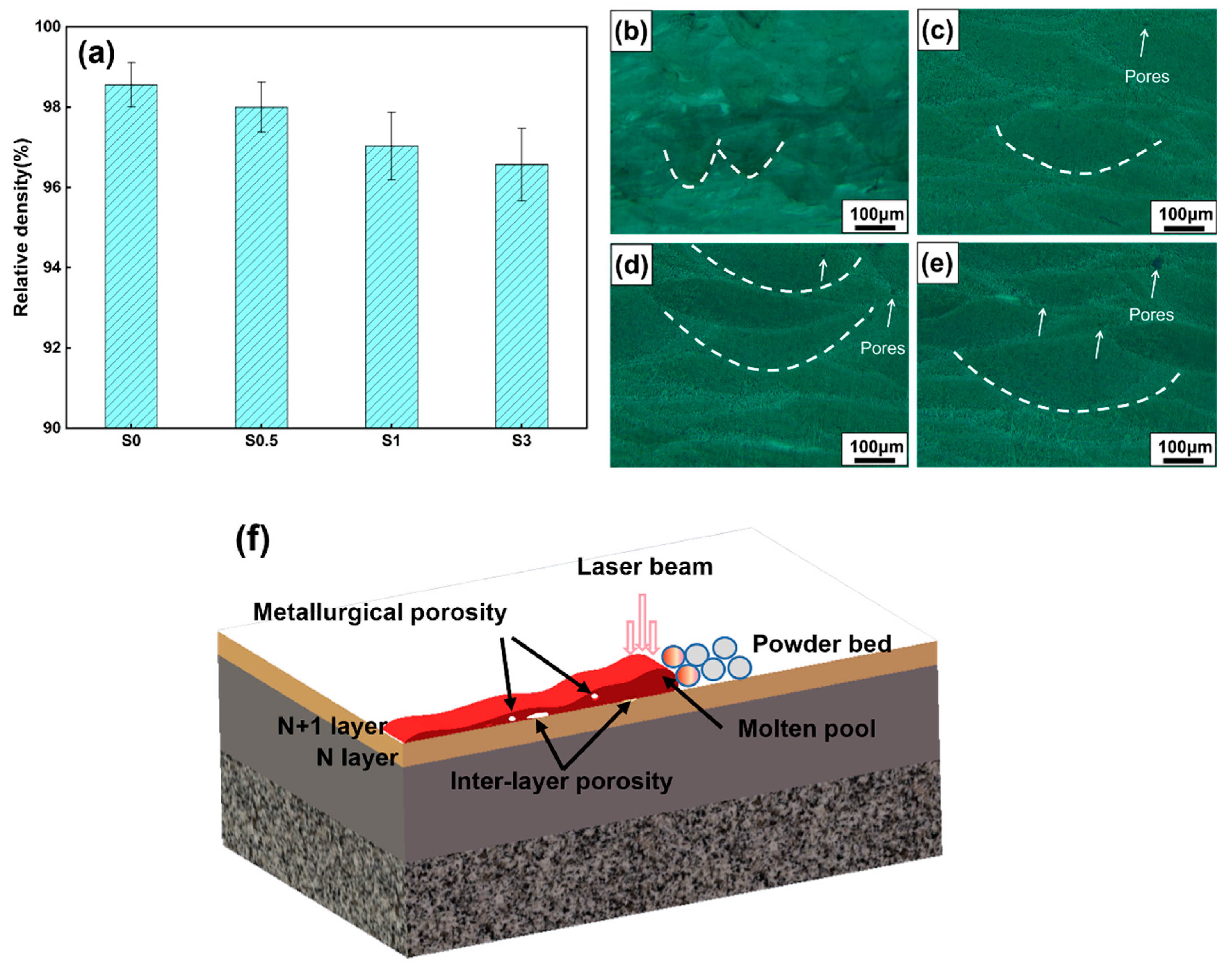
3.1. Densification Research

The relative density of the printed cubes is calculated using the Archimedean drainage method, which is the ratio of the actual density of the sample to the theoretical density. This ratio is calculated by the following formula:
D = m 1 ρ L m 2 ρ 0 × 100 %
where D is relative density, m1 is the mass in air, m2 is the mass of the liquid discharged from the sample, ρL is the density of the liquid used in the drainage method and ρ0 is the theoretical density of the material. Each sample was measured seven times, and the final results were averaged. The relative density results of each sample measured are shown in Figure 4a. The results show that at a bulk energy density of 305.56 J/mm, the density gradually decreases from 98.56% to 96.57% with increasing LaB6 content. As shown in Figure 4b–e, the sides of the printed samples showed fish scale-like melt channel sections. As LaB6 content increases, the depth and width of the melt pool gradually increases. LaB6 powder has a higher laser absorption rate compared to Ti-6Al-4V, and powder with higher LaB6 content receives more energy at the same volume, making the molten pool larger and deeper. As LaB6 content increases, the number of pores at the edge of the melt channel begins to increase, and the increase in the number of pores is reflected by a decrease in the relative density of the sample. A schematic diagram of the formation of pores in the printing process is shown in Figure 4f, and the formation of pores in the printing process is mainly distributed at the junction of the melt channel and inside the melt channel. The formation of pores is mainly due to the very short solidification time of the melt pool, which prevents the gas in the powder void from being able to escape.

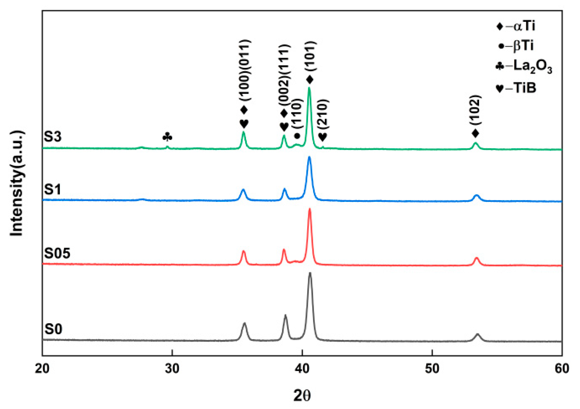
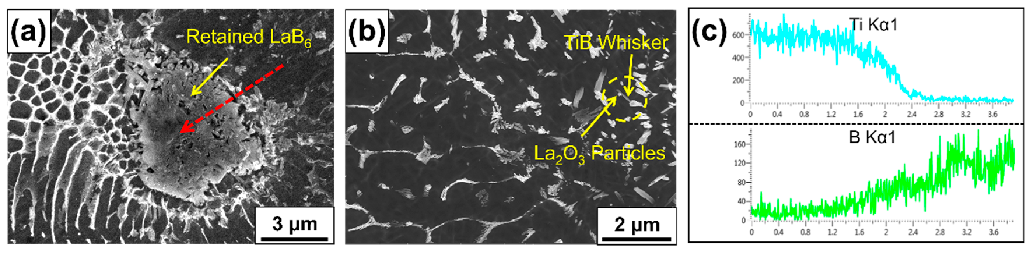
3.2. Phase Evolution and Identification

Figure 5 shows the XRD patterns for samples with different content. All samples detected strong α-Ti phase diffraction peaks, and β-Ti diffraction peaks were also detected in samples with LaB6 added, though not in all samples. Concerning the diffraction peak of LaB6, weak diffraction peaks for TiB and La2O3 can be detected at 3% LaB6 content, indicating that most of the LaB6 reacts with Ti to form the desired products. When LaB6 content is low, the reaction yields less TiB and La2O3 and the diffraction peaks for TiB and La2O3 are not observed.
During SLM fabrication of the LaB6/Ti-6Al-4V compound, self-propagating chemical reactions between uniformly distributed LaB6 and Ti in the molten state should be performed as follows:
12Ti + 2LaB6 + 3[O] = 12TiB + La2O3
According to the Ti-B binary phase diagram and the Ti-La binary phase diagram, due to the high melting point of La2O3, part of the La2O3 will first solidify and precipitate before TiB with a higher concentration then begins to do so, and β-Ti is present in the form of TiB and La2O3 surfaces. Solidification and precipitation at the core site and in situ synthesis solidification and precipitation processes are described as follows:
Ti + LaB6→L(Ti, TiB, La, La2O3I)→La2O3I + LI→β-Ti + LII→TiB + β-Ti→α-Ti + La + [O]→La2O3II
In order to study the evolution mechanism and orientation relationship of the TiB phase, La2O3 phase and α-Ti phase in detail, the S05 sample was observed and analyzed through TEM. Figure 6a shows a bright field image of the S05 sample. The three phases are clearly demarcated. The α-Ti phase is the main phase, and the needle-like TiB phase and the granular La2O3 phase are distributed in the α-Ti phase. A large number of dislocations are found around it, and these add to the strength of the material. Figure 6b,c show high-resolution TEM images of the grain boundaries between the La2O3 phase and α-Ti phase and the TiB phase and α-Ti phase. The calculated lattice fringe spacings of 0.212 nm and 0.225 nm correspond to the crystal planes of (101) α-Ti and (102) La2O3 that were calculated, and the lattice fringe spacings of 0.209 nm and 0.239 nm were calculated to correspond to the crystal planes of (101) α-Ti and (201) TiB; the crystal planes parallel to each other will be mismatched, and there are dislocations in the phase interface to alleviate the so-called mismatch [20]. In addition, it can be seen that the two reinforcing phases are well combined with the α-Ti matrix, without defects such as pores or cracks. Energy dispersive X-ray (EDX) analysis was introduced, and the samples were analyzed. The results are shown in Figure 6d,e and B was detected at the white elongated grains (point 1) element, indicating that the white elongated grains are TiB (length was in the range of 0.1–1 μm and width was less than 200 nm). La and O elements were detected in the black granular grains (point 2), indicating that the black granular grains were La2O3 with a diameter of less than 100 nm.

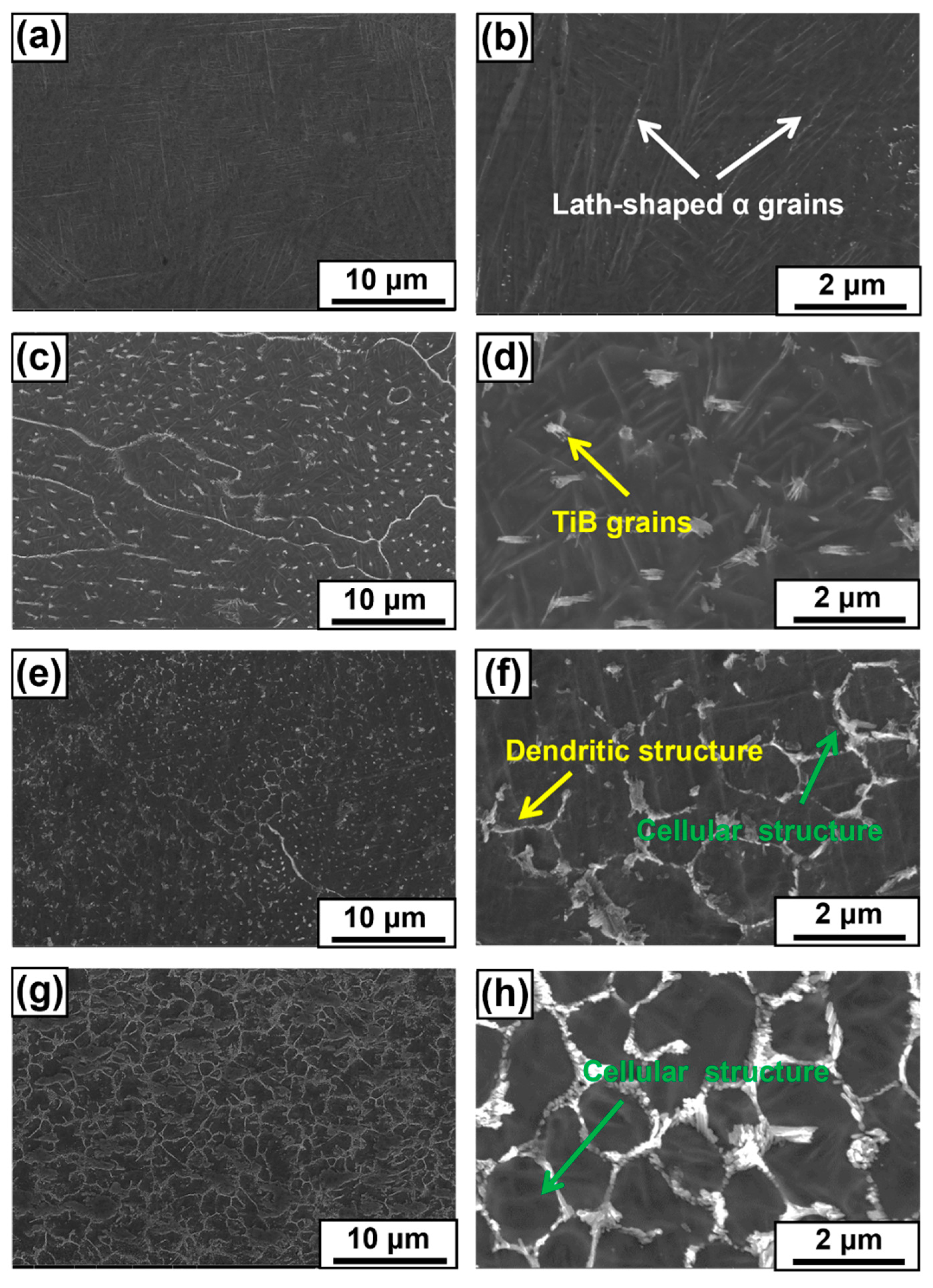
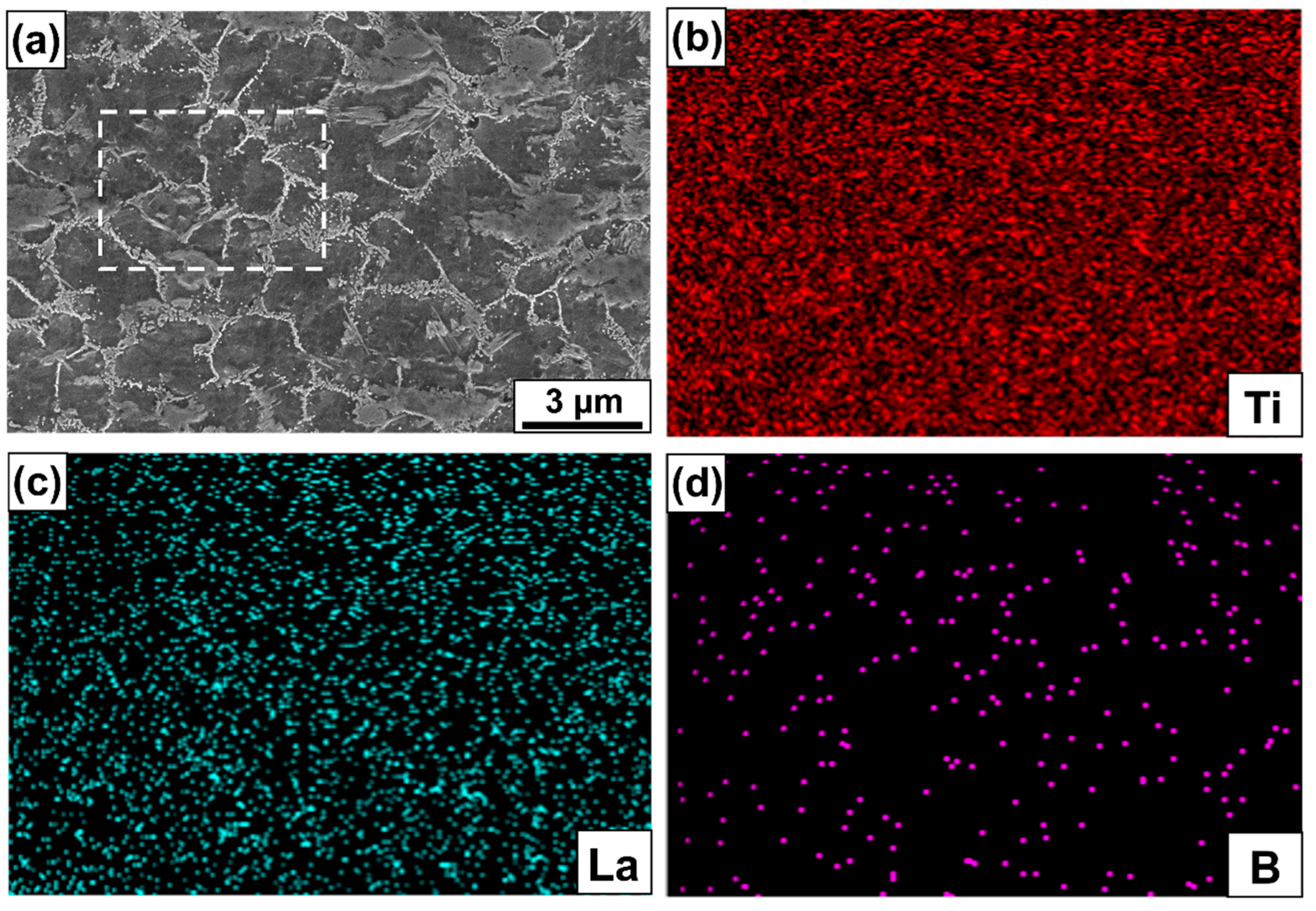
3.3. Microstructure Evolution

Figure 7 shows the microstructure of the top surface of the samples with different content. The microstructure morphology of samples is greatly affected by LaB6. The top surface of the S0 sample is mainly composed of lath-like α-Ti. When 0.5 wt% LaB6 is added, the needle-like reinforcing phase particles are evenly distributed in the sample, and the size of the lath-like α-Ti becomes smaller because the first precipitation ceramic phase hinders the growth of lath-like α-Ti [21]. When 1 wt% LaB6 is added, homogeneous and discrete spicules begin to aggregate and grow, subsequently becoming dominated by dendrites. At the same time, a small number of cellular hybrid structures are present, and the growing young branches have curved features. When LaB6 content continues to increase to 3 wt%, the microstructure of the sample shows cellular structures connected to each other with dendrites and the cellular structure becomes the α-Ti grain boundary [22]. The microstructural features of the composite samples are affected by thermal convection in the molten pool during the printing process [23].
Figure 8 shows the microstructure of the S3 sample and the EDS map in the dashed box. For the presence of TiB and La2O3 phases, we analyze the distribution of Ti, B and La elements in the cross section of the S3 sample using EDS. The tissue morphology is a white cell-like structure precipitated in a gray matrix. The EDS results show that the gray matrix is rich in Ti and La elements, while the B element is concentrated in the white precipitates. Combined with the XRD pattern, the white spicule-like precipitate can be identified as TiB. The La element is evenly distributed in the matrix, and there is no local aggregation phenomenon, indicating that La2O3 is not formed by precipitation and solidification after the transformation of β-Ti into α-Ti (the solubility of La2O3 in β-Ti is higher than that of α-Ti) and then combined. The Gibbs free energy of La2O3 is low, and it can be inferred that La2O3 existed before the nucleation of β-Ti. Instead of La2O3, as proposed by Yang et al. [24], it is formed after β-Ti nucleation. Similar conclusions were obtained by Bermingham et al. [25].
Figure 9 shows the microstructure morphology of the unmelted LaB6 particles in the S3 sample and the distribution of B and Ti in the EDS pattern. Coexisting micro-sized TiB whiskers and La2O3 grains were observed in the printed samples. Linear EDS was performed from the matrix to the position of the red dashed line of the LaB6 particle. The B content gradually increases and the Ti content gradually decreases along the direction of the red dashed line. Combining the SEM and EDS results, the residual particle can be identified as LaB6. By observing the residual LaB6 particles through SEM, it was found that the TiB phase precipitates and grows from the surface of the LaB6 phase and aggregates into dendritic and cell-like structures. The tissue changes with content in the same trend. The chemical potential difference of B at the interface between LaB6 particles and Ti liquid is the driving force for its dissolution, and the convective flow in the molten pool promotes the rapid dissolution of LaB6 particles. Due to the extremely short heating and cooling times during the SLM process, some of the large particles or agglomerated micron-sized LaB6 particles remain during the printing process and become heterogeneous nucleation sites for TiB whiskers. Since the reaction zones of the TiB and La2O3 phases are formed around the LaB6 particles, the LaB6 and the Ti matrices have better wettability and metallurgical bonding properties.

3.4. Mechanical Properties
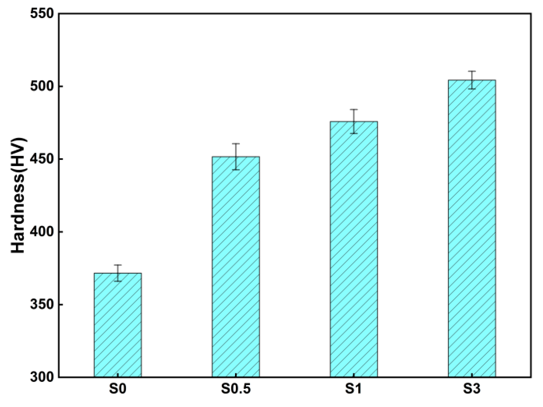
3.4.1. Hardness

The hardness of samples with different content is shown in Figure 10. As LaB6 content increases, the hardness of each sample gradually increases. Among them, the hardness of the S05 sample is 451.63 ± 8.95 HV, which is 21.56% higher than that of the S0 sample. Other samples have higher hardness than the S0 sample. Compared to the S1 sample, the LaB6 content of the S3 sample is three times higher, and the hardness is increased by only 6.0%.

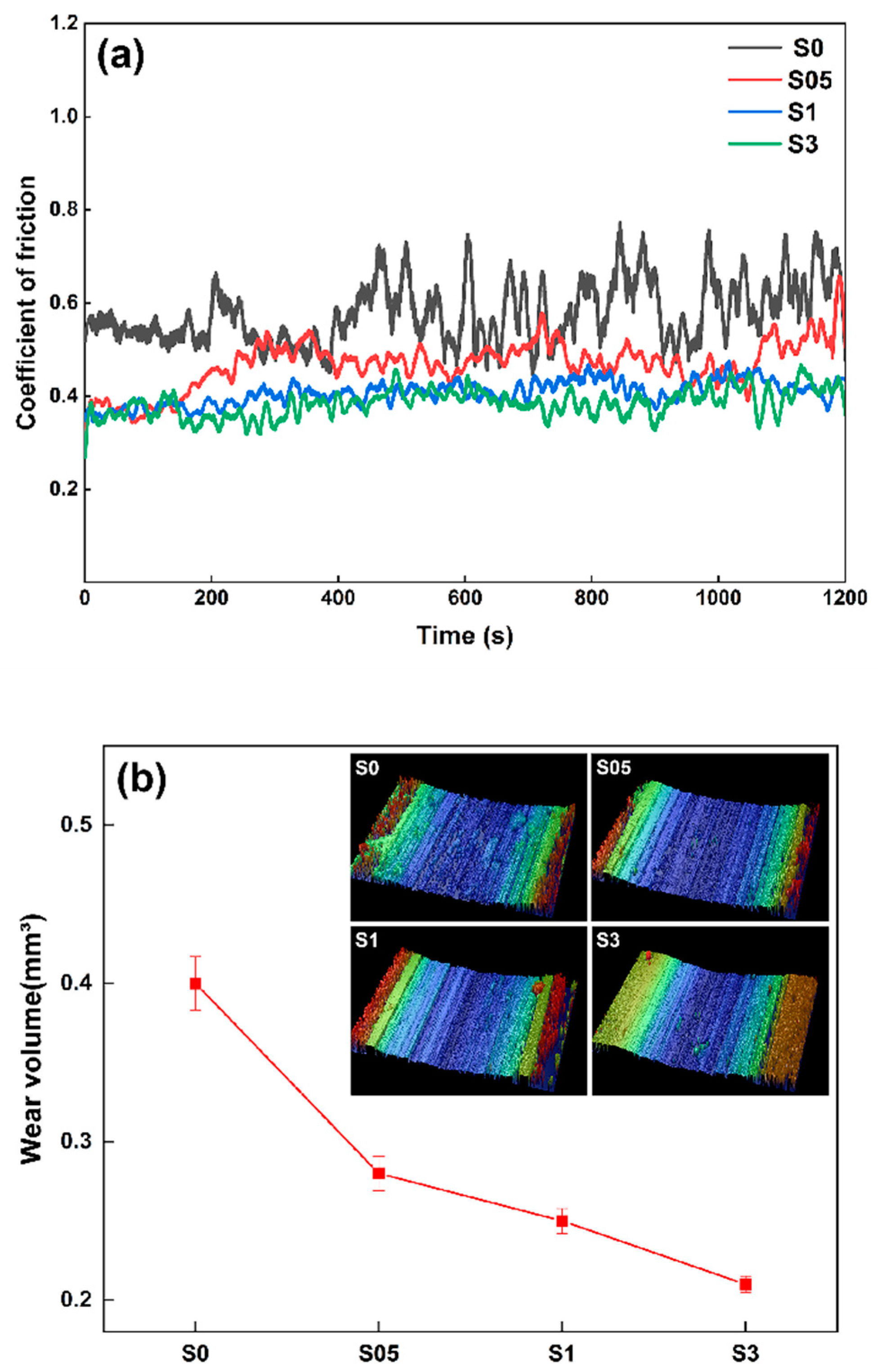
3.4.2. Wear Resistance

Figure 11 shows the coefficient of friction (COF) and wear volume of samples with different LaB6 content. Figure 11a shows the change in friction coefficient with LaB6 content. The results show that LaB6 content has a significant effect on the friction coefficient of the sample. As LaB6 content increases, the friction coefficient of the sample gradually decreases, and the wear resistance of the sample improves. The average friction coefficient of the S0 sample is 0.49 and the coefficient fluctuates strongly during friction, which is a non-stationary process. Figure 11b shows the change in friction volume with LaB6 content. With the increase in LaB6 content, wear volume gradually decreases, which is the same as the change law of the friction coefficient. The maximum wear volume of the S0 sample is 0.4 ± 0.017 mm3, and the wear volume of the S05 sample is 0.28 ± 0.011 mm3, which is 30% smaller than that of the S0 sample. The wear volume of the S3 sample is 0.21 ± 0.005 mm3, which is about half that of the S0 sample. A 3D map of the working surface shows that the wear surface of sample S0 is relatively rough, while the roughness of the other samples is small. The smaller the surface roughness, the more stable the friction process. In addition, the roughness reflects the sample’s wear resistance. Generally speaking, the smaller the roughness, the better the wear resistance of the sample.
Figure 12 shows the abrasion surface morphologies of samples with different LaB6 content. Under the same experimental conditions, furrows and worn fragments appear on the wear surfaces of the four samples, which are an abrasive form of wear. Increasing LaB6 content not only makes the furrows shallower and narrower, but also reduces the amount of worn fragments. Comparing and looking at the worn fragments of each sample, it can be seen that the worn fragments of the S0 sample are in the form of clumps, and the worn fragments of the S05, S1 and S3 samples are in the form of flakes. As LaB6 content increases, the size of the worn fragments gradually decreases. The surface grooves of the S0 sample are deep and broad and covered with a large amount of worn debris, representing very severe wear. Such large-area surface damage, severe plastic deformation and metal flow are considered to be the characteristics of adhesive wear. The granular wear fragments are embedded in the wear surface and wear debris is added to the wear process as a third party, thus accelerating the wear failure process. The sample underwent a severe abrasive abrasion process.

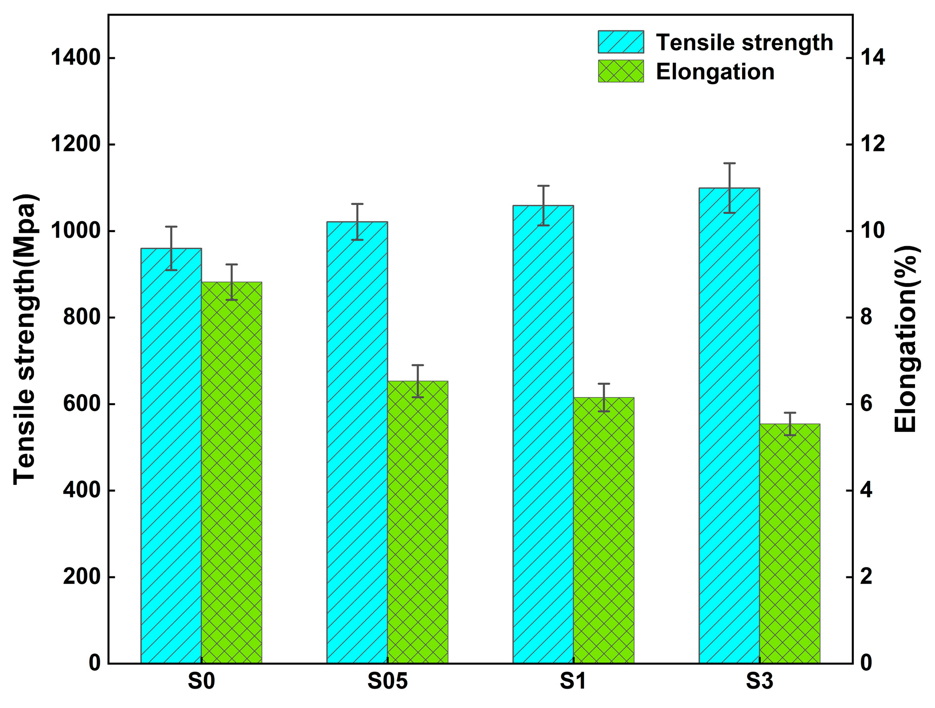
3.4.3. Room Temperature Stretching

Figure 13 shows ultimate tensile strength (UTS) and elongation after the fracture of samples with LaB6 content. It can be concluded that the UTS of the composite samples gradually increases with LaB6 content, while elongation after fracture gradually decreases with LaB6 content. The UTS of the S0 sample is 959.95 ± 70.15 MPa, and the elongation after fracture is 8.8 2 ± 0.61%. Compared to S0, the S05, S1 and S3 samples showed an increase in tensile strength of 6.4%, 10.3% and 14.5%, respectively, while elongation after fracture decreased by 26.0%, 30.3% and 37.2%, respectively. Although the addition of LaB6 to Ti-6Al-4V increases the UTS of the sample to some extent, it greatly reduces the post-fracture elongation of the sample.
Figure 14 shows the tensile fracture morphology of samples with different LaB6 content at room temperature. A large area of nearly equidistant dimples is found in the tensile fracture morphology of the S0 sample, which belongs to the ductile fracture mode. The fracture morphologies of the S05, S1 and S3 samples are all composed of a large number of near-equiaxial dimples, cleavage steps and tear ridges, which belong to the brittle–ductile mixed fracture type. The strength of the TiB and La2O3 phases generated by the reaction is higher than that of the matrix α-Ti phase, and strain capacity is lower than that of the α-Ti phase. Here, micro-holes are created when the external force received by the sample is larger than the interfacial bonding force. When the tension is continued, micro-holes grow and aggregate to form cracks [26]. In addition, Ti-6Al-4V is an α + β-type alloy. It is composed of a large number of α-Ti phases with a hexagonal close-packed structure (HCP) and a small number of β-Ti phases with a body-centered cubic structure (BCC). The strain capacity of the BCC is stronger than the HCP, and this difference in strain capacity also tends to lead to the formation of micropores at the α and β interfaces under tension [27]. The fracture morphology is consistent with the tensile test elongation results.

4. Discussion

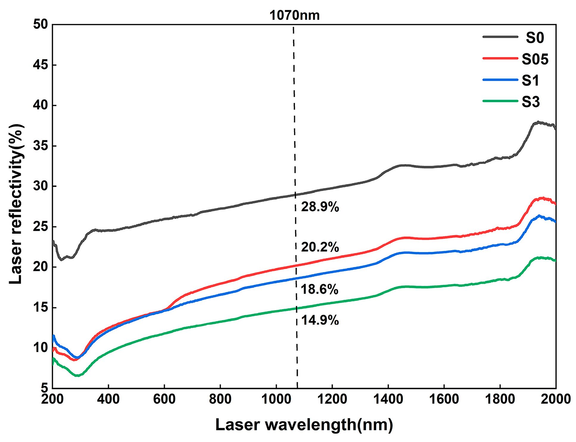
4.1. Effect of LaB6 Content on the Property of Fabrication

Relative density is frequently used to evaluate SLM formability. As LaB6 content increases, the relative density of the sample gradually decreases, reaching a maximum relative density of 98.56% and a minimum of 96.57%. Side face metallography has shown the presence of micropores distributed in fish-scale melt track profiles, which can be classified as interlayer and metallurgical pores. In both types, the interlayer pores are mainly caused by the extremely short cooling time during the printing process, resulting in the incomplete fusion of adjacent melt channels [28]. Metallurgical pores occur primarily due to the evaporation of volatile elements and the precipitation of gas when the metal solidifies. The boiling point of Al in Ti-6Al-4V is 2519 °C, while the melting point of LaB6 is 2715 °C. LaB6 is still solid when Al begins to evaporate. Solid particles impede the flow of the surrounding molten metal liquid into the void left by the evaporation of Al, thus forming a metallurgical pore. In the experiment, to prevent the printed composite samples from producing cracks and other manufacturing defects, we used a higher laser energy density to ensure that the LaB6 particles were completely melted. In the instability, the surface energy of the molten pool is reduced, either forming a solarization effect or causing small droplets to splash out of the molten pool, thus resulting in a decrease in the density of the sample. As shown in Figure 15, the laser reflectivity gradually decreases, which indicates that the laser absorption rate of the LaB6/Ti-6Al-4V composite powder at the 1070 nm wavelength is larger than the pure Ti-6Al-4V powder and increases with LaB6 content. Firstly, this is mainly due to the higher laser absorptivity of the ceramic particles [29]. Secondly, as can be seen from Figure 1, the mixed powder is a relatively large Ti-6Al-4V powder with fine reinforcing phase particles attached to the surface, which will improve the surface roughness of the Ti-6Al-4V powder and reduce laser reflection. Therefore, an appropriate amount of LaB6 helps to improve the processing performance of the material; however, too much LaB6 content is not only unfavorable for the relative density of the printed parts, but also causes LaB6 to aggregate in the matrix and become a crack source in the printed parts. Thus, in order to reduce cracks and ensure the relative density of printed parts, it is necessary to control LaB6 content.

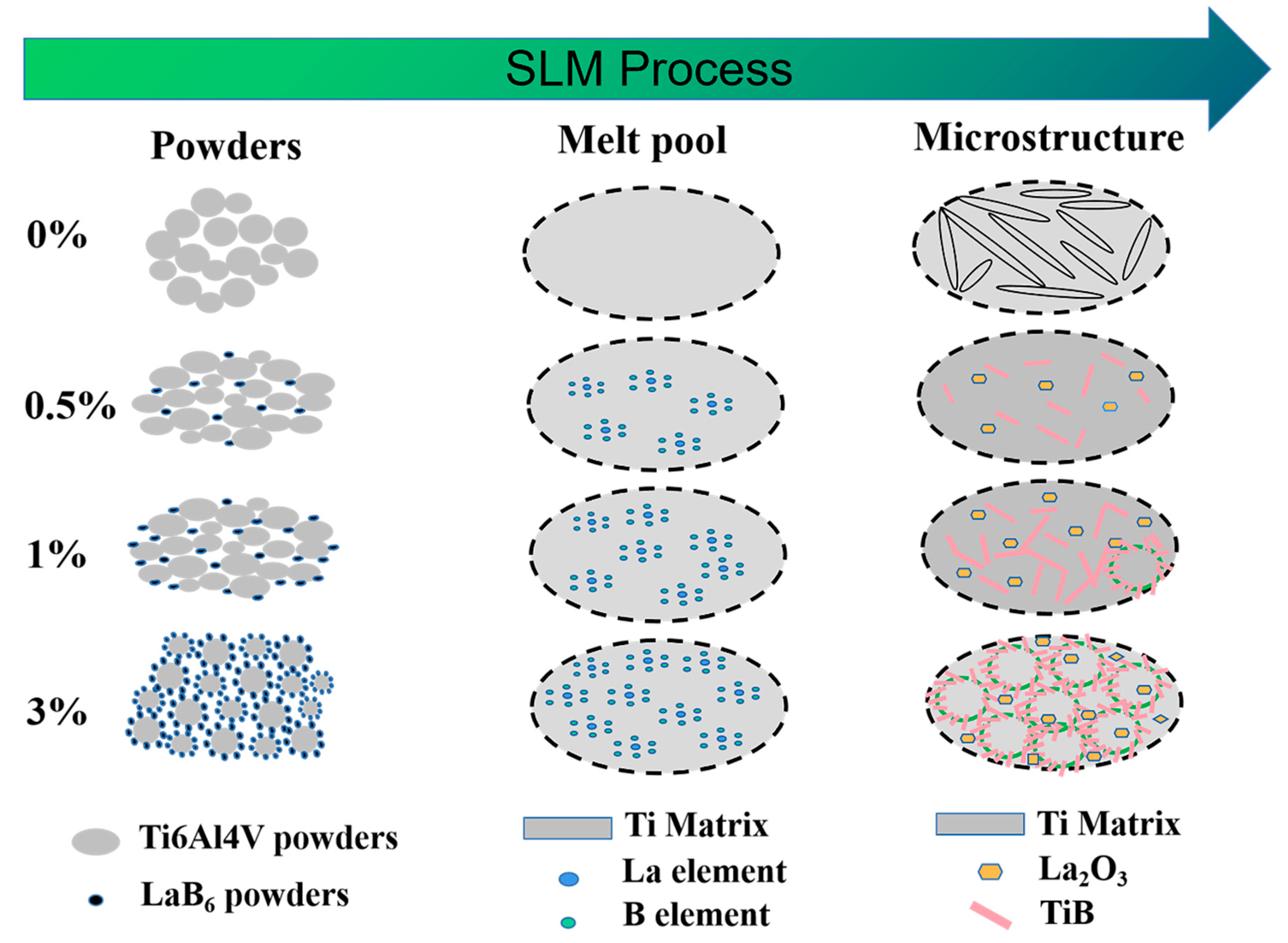
4.2. Effect of LaB6 Content on the Microstructure Evolution of Composites

Figure 16 shows a schematic diagram of the microstructure formation mechanism for samples with different content. Due to the Gaussian distribution of the laser and the fast cooling rate of the SLM process, a large temperature gradient will be generated between the center of the molten pool and the surrounding region, which will then form a surface tension gradient. The surface tension gradient drives the composite solution to flow from the low surface tension region to the high surface tension region, forming Marangoni convection. The Marangoni number Ma is used to indicate the magnitude of convective intensity:
M a = L Δ γ μ v
where L is the length of the molten pool, Δ γ is the surface tension change value, μ is the viscosity of molten liquid and v is the viscosity of the flow. Compared to Ti-6Al-4V powder, LaB6 particles have higher laser absorptivity. With the same treatment parameters, the higher the LaB6 content, the more energy is absorbed by the powder, which reduces dynamic viscosity and increases the convective strength (Ma) of the Marangoni flow.
During the dissolution of LaB6, the powder is subjected to a high-energy laser beam in order to form a molten pool in which a temperature gradient is formed, resulting in a Marangoni flow towards the center of the molten pool. Since LaB6 has a higher laser absorption rate than Ti-6Al-4V, a temperature gradient is also generated around LaB6, forming a small Marangoni flow. Adjacent Marangoni flows easily converge to form a dendritic structure. Increasing LaB6 content allows the compound powder to absorb more energy and leads to the convection of the Marangoni flow becoming more intense, thus resulting in a cell-like structure.
During compound powder printing, the large cooling rate of the SLM process limits the diffusion of B, resulting in the aggregation of TiB that in turn is affected by Marangoni convection, thus leading to the formation of dendritic and cellular structures. An increase in LaB6 content results in an increase in the concentration of TiB produced, which in turn results in a greater tendency to aggregate. As a result, the tissue gradually aggregates and grows from discrete needle-like structures to dendritic structures and eventually develops into cellular structures. In contrast to S0, the TiB whiskers and La2O3 particles precipitated in S05, S1 and S3 limit the growth of Ti cores, resulting in grain refinement.

4.3. Effect of LaB6 Content on the Mechanical Properties of Composites

Grain refinement in the SLM process is affected by a variety of factors. Tamirisakandala et al. [30] found that grain refinement of titanium alloys occurs when the nucleation rate is greater than the growth rate and vice versa. By affecting the properties of the solid–liquid interface, B drives an increase in the nucleation rate, which then plays the role of grain refinement. The resistance formula for grain growth is as follows:
F = 3 f γ b / 2 r
where F represents the forces that hinder grain growth, f is second phase particle content, γ b is the surface tension between the α-Ti phase and reinforcing phase and r is the size of the reinforcing phase. It can be seen from the above equation that as LaB6 content increases, the content of the reinforcing phase increases and grain growth resistance and grain size decrease. The microstructure of the SLM-fabricated samples shows fine grains due to the short cooling time, which limits grain growth.
LaB6 can greatly improve the hardness and wear resistance of Ti-6Al-4V alloy. Sulima et al. [31] pointed out that the microhardness of the material determines its wear resistance. Here, we only discuss hardness. The hardness of composites is affected by the combination of relative density and grain size. The higher the relative density of the sample, the stronger the resistance to plastic deformation of the micro-domain and the greater the hardness. Inadequate fusion during the printing process creates irregular defects at the edges of the molten pool, which may well cause a reduction in hardness. When the relative density of the sample is at a high level, the grain size determines the hardness of the sample, and the material hardness and the average grain size satisfy the Hall–Petch relation:
H = H 0 + k W 1 / 2
where H is the Vickers hardness of the sample, H 0 and k are the constants, respectively, and W is the average size of all grains. According to Equation (6), the finer the sample grain, the harder the sample.
During the SLM fabrication of the composite, the increase in the number of nucleation sites in the sample with higher LaB6 content suppresses the growth of matrix grains to form finer needle-like Ti, which strengthens fine crystals. Moreover, the reaction generates TiB- and La2O3-enhanced particles that pin and hinder dislocation motion. As can be seen from the tissue photos and EDS, the in situ reaction products bind well to the matrix and are uniformly distributed over the whole, which plays a role in dispersal enhancement. Sen et al. [32] pointed out that only 0.02 g of B could be dissolved in 100 g of titanium. It is very easy to form supersaturated solid solutions when the cooling rate of SLM is too high, leading to a solid solution strengthening effect. Jin et al. [33] also reached the same conclusion in their study.
Analysis shows that the UTS of the sample gradually increases with LaB6 content. According to the theory of shear hysteresis, the strength of TiB + La2O3/Ti-6Al-4V composites can be expressed as follows:
σ M M C = σ m V f s + 4 / 4 + 1 V f
In the above formula, σ M M C is the strength of the TiB + La2O3/Ti-6Al-4V composite material, σ m is the strength of the Ti-6Al-4V alloy, V f is TiB and La2O3 reinforcing phase content and s is the aspect ratio of the TiB and La2O3 reinforcing particles. It can be seen from Equation (7) that the number and morphology of TiB and La2O3 reinforcing phases affects the tensile strength of the composite. Adding TiB and La2O3 reinforcing particles to the Ti-6Al-4V alloy results in α-Ti grain refinement and increases the strength of the Ti-6Al-4V alloy. The greater the number of TiB and La2O3 reinforcement particles, the greater the aspect ratio and the higher the strength of the composites. Two kinds of brittle and hard particles are generated in the composite material, TiB and La2O3. The presence of TiB and La2O3 particles hinders the motion of dislocations and generates a large number of dislocations around them, which enhances the strength of the TiB + La2O3/Ti-6Al-4V composite at the expense of plasticity. Elongation of the composites decreased with increasing LaB6 content.
We compared the mechanical properties of the TiB + La2O3/Ti-6Al-4V composite, and the results are shown in Table 2. According to the results, the SLM method is a potential formation method that benefits the in situ reaction between Ti-6Al-4V and LaB6. Additionally, the fast cooling process also guarantees the small size of reinforcement particles.

5. Conclusions

In this study, TiB + La2O3/Ti-6Al-4V composites were successfully prepared by in situ reaction using the selective laser melting method starting from a micro-sized LaB6/Ti-6Al-4V powder system. The effect of LaB6 content on the fabrication properties, microstructure evolution and mechanical properties of composites was systematically studied and the main conclusions drawn are as follows:
(1) As LaB6 content increases, the relative density of the sample gradually decreases from 98.56% to 96.57%. Of the samples tested, S0, S05 and S1 had higher relative density, with a relative density above 97%. The sides of each sample show a fish-scale melt channel profile, with the depth and width of the melt pool gradually increasing with LaB6 content due to the effect of laser absorptivity.
(2) During the printing process, the microstructure of the sample gradually aggregates due to the influence of the Marangoni flow and grows from a discrete needle-like structure to a dendritic structure with increasing LaB6 content, finally developing into a cell-like structure.
(3) After the addition of LaB6 to the Ti-6Al-4V alloy, the Vickers hardness, wear resistance and ultimate tensile strength of the TiB + La2O3/Ti-6Al-4V composite were enhanced due to grain refinement strengthening, dispersion strengthening and solid solution strengthening; however, some of the plasticity of the material was lost. The S3 sample had the most significant strengthening effect. Compared to the S0 sample, hardness was increased by 35.71%, wear volume was reduced by 47.5%, tensile strength was increased by 14.5% and elongation after fracture was reduced by 37.2%. The S05 sample had the best formability and is best suited for production practice.

Author Contributions

Conceptualization, D.H. and H.W.; methodology, D.H. and H.W.; software, D.H.; validation, H.W., W.H. and G.L.; formal analysis, D.H.; investigation, X.C.; resources, W.H.; data curation, Y.W.; writing—original draft preparation, D.H.; writing—review and editing, D.H.; visualization, D.H.; supervision, D.H.; project administration, W.H.; funding acquisition, W.H. and H.W. All authors have read and agreed to the published version of the manuscript.

Funding

This work was financially supported by the National Natural Science Foundation of China (No. 52205340), the Natural Science Foundation of Fujian Province (No. 2021J05214), the Fujian Industry University Cooperation Project (Grant No.2020H6018), and the Fujian Innovation Center of Additive Manufacturing (Grant Nos. ZCZZ202-04, ZCZZ202-05).

Data Availability Statement

The data that support the findings in this paper are available from the corresponding authors upon reasonable request.

Conflicts of Interest

The authors declare that they have no known competing financial interest or personal relationships that could have appeared to influence the work reported in this paper.

References

  1. Kadirgama, K.; Harun, W.S.W.; Tarlochan, F.; Samykano, M.; Ramasamy, D.; Azir, M.Z.; Mehboob, H. Statistical and optimize of lattice structures with selective laser melting (SLM) of Ti6AL4V material. Int. J. Adv. Manuf. Technol. 2018, 97, 495–510. [Google Scholar] [CrossRef]
  2. Attar, H.; Ehtemam-Haghighi, S.; Kent, D.; Dargusch, M.S. Recent developments and opportunities in additive manufacturing of titanium-based matrix composites: A review. Int. J. Mach. Tools Manuf. 2018, 133, 85–102. [Google Scholar] [CrossRef]
  3. Imayev, V.M.; Gaisin, R.A.; Imayev, R.M. Microstructure and mechanical properties of near α titanium alloy based composites prepared in situ by casting and subjected to multiple hot forging. J. Alloys Compd. 2018, 762, 555–564. [Google Scholar] [CrossRef]
  4. Traxel, K.D.; Bandyopadhyay, A. Reactive-deposition-based additive manufacturing of Ti-Zr-BN composites. Addit. Manuf. 2018, 24, 11. [Google Scholar] [CrossRef]
  5. Cai, C.; He, S.; Li, L.; Teng, Q.; Song, B.; Yan, C.; Shi, Y. In-situ TiB/Ti-6Al-4V composites with a tailored architecture produced by hot isostatic pressing: Microstructure evolution, enhanced tensile properties and strengthening mechanisms. Compos. Part B Eng. 2019, 164, 546–558. [Google Scholar] [CrossRef]
  6. Duan, H.; Han, Y.; Lv, W.; Mao, J.; Wang, L.; Zhang, D. Effect of solid carburization on surface microstructure and hardness of Ti-6Al-4V alloy and (TiB + La2O3)/Ti-6Al-4V composite. Trans. Nonferrous Met. Soc. China 2016, 26, 1871–1877. [Google Scholar] [CrossRef]
  7. Guo, X.; Wang, L.; Qin, J.; Lv, W.; Zhang, D. Microstructure and mechanical properties of (TiB + La2O3)/Ti composites heat treated at different temperatures. Trans. Nonferrous Met. Soc. China 2014, 24, 1737–1743. [Google Scholar] [CrossRef]
  8. Li, Y.; Xiao, L.; Lu, W.; Qin, J.; Zhang, D. Creep rupture property of in situ synthesized (TiB + La2O3)/Ti composite. Mater. Sci. Eng. A 2008, 488, 415–419. [Google Scholar] [CrossRef]
  9. Li, J.; Han, Y.; Yang, D.; Mao, J. Effect of Heat Treatment on Creep Properties of in situ Synthesized (TiB + La2O3)/Ti Composite. Front. Mater. 2019, 6, 10. [Google Scholar] [CrossRef]
  10. Han, Y.; Duan, H.; Lu, W.; Wang, L.; Zhang, D. Fabrication and characterization of laminated Ti-(TiB + La2O3)/Ti composite. Prog. Nat. Sci. Mater. Int. 2015, 25, 453–459. [Google Scholar] [CrossRef] [Green Version]
  11. Yi, X.; Wang, H.; Sun, K.; Shen, G.; Meng, X.; Gao, Z.; Cai, W. Tailoring martensitic transformation and mechanical properties of Ti–Ni composite reinforced by network structure of in-situ TiB and La2O3 phase. Vacuum 2021, 184, 109894. [Google Scholar] [CrossRef]
  12. Sun, X.; Li, H.; Han, Y.; Li, J.; Mao, J.; Lu, W. Compressive response and microstructural evolution of bimodal sized particulates reinforced (TiB + La2O3)/Ti composites. J. Alloys Compd. 2018, 732, 524–535. [Google Scholar] [CrossRef]
  13. Song, B.; Wang, Z.W.; Yan, Q.; Zhang, Y.J.; Zhang, J.L.; Cai, C.; Wei, Q.S.; Shi, Y.S. Integral method of preparation and fabrication of metal matrix composite: Selective laser melting of in-situnano/submicro-sized carbides reinforced iron matrix composites. Mater. Sci. Eng. A 2017, 707, 478–487. [Google Scholar] [CrossRef]
  14. Li, R.; Wang, M.; Yuan, T.; Song, B.; Chen, C.; Zhou, K.; Cao, P. elective laser melting of a novel Sc and Zr modified Al-6.2Mg alloy: Processing, microstructure, and properties. Powder Technol. 2017, 319, 117–128. [Google Scholar] [CrossRef]
  15. Li, R.; Niu, P.; Yuan, T.; Cao, P.; Chen, C.; Zhou, K. Selective laser melting of an equiatomic CoCrFeMnNi high-entropy alloy: Processability, non-equilibrium microstructure and mechanical property. J. Alloys Compd. 2018, 746, 125–134. [Google Scholar] [CrossRef]
  16. Gu, D.; Meng, G.; Li, C.; Meiners, W.; Poprawe, R. Selective laser melting of TiC/Ti bulk nanocomposites: Influence of nanoscale reinforcement. Scr. Mater. 2021, 67, 185–188. [Google Scholar] [CrossRef]
  17. Krakhmalev, P.; Yadroitsev, I. Microstructure and properties of intermetallic composite coatings fabricated by selective laser melting of Ti–SiC powder mixtures. Intermetallics 2014, 46, 147–155. [Google Scholar] [CrossRef]
  18. Cai, C.; Radoslaw, C.; Zhang, J.; Yan, Q.; Wen, S.; Song, B.; Shi, Y. In-situ preparation and formation of TiB/Ti-6Al-4V nanocomposite via laser additive manufacturing: Microstructure evolution and tribological behavior. Powder Technol. 2018, 342, 73–84. [Google Scholar] [CrossRef]
  19. Xia, M.; Liu, A.; Hou, Z.; Li, N.; Chen, Z.; Ding, H. Microstructure growth behavior and its evolution mechanism during laser additive manufacture of in-situ reinforced (TiB + TiC)/Ti composite. J. Alloys Compd. 2017, 728, 436–444. [Google Scholar] [CrossRef]
  20. Li, W.; Yang, Y.; Liu, J.; Zhou, Y.; Li, M.; Wen, S.; Wei, Q.; Yan, C.; Shi, Y. Enhanced nanohardness and new insights into texture evolution and phase transformation of TiAl/TiB2 in-situ metal matrix composites prepared via selective laser melting. Acta Mater. 2017, 136, 90–104. [Google Scholar] [CrossRef]
  21. Su, Y.; Luo, S.C.; Meng, L.; Gao, P.; Wang, Z.M. Selective Laser Melting of In Situ TiB/Ti6Al4V Composites: Formability, Microstructure Evolution and Mechanical Performance. Acta Metall. Sin. (Engl. Lett.) 2020, 33, 774–788. [Google Scholar] [CrossRef]
  22. Han, C.; Babicheva, R.; Chua, J.D.Q.; Ramamurty, U.; Tor, S.B.; Sun, C.-N.; Zhou, K. Microstructure and mechanical properties of (TiB + TiC)/Ti composites fabricated in situ via selective laser melting of Ti and B4C powders. Addit. Manuf. 2020, 36, 101466. [Google Scholar] [CrossRef]
  23. Kovalev, O.B.; Gurin, A.M. Multivortex convection of metal in molten pool with dispersed impurity induced by laser radiation. Int. J. Heat Mass Transf. 2014, 68, 269–277. [Google Scholar] [CrossRef]
  24. Yang, Z.; Lu, W.; Zhao, L.; Qin, J.; Zhang, D. Microstructure and mechanical property of in situ synthesized multiple-reinforced (TiB+TiC+La2O3)/Ti composites. J. Alloys Compd. 2008, 455, 210–214. [Google Scholar] [CrossRef]
  25. Bermingham, M.J.; McDonald, S.D.; Dargusch, M.S. Effect of trace lanthanum hexaboride and boron additions on microstructure, tensile properties and anisotropy of Ti-6Al-4V produced by additive manufacturing. Mater. Sci. Eng. A 2018, 719, 1–11. [Google Scholar] [CrossRef]
  26. Li, D.; Wang, K.; Yan, Z.; Cao, Y.; Misra RD, K.; Xin, R.; Liu, Q. Evolution of microstructure and tensile properties during the three-stage heat treatment of TA19 titanium alloy. Mater. Sci. Eng. A 2018, 716, 157–164. [Google Scholar] [CrossRef]
  27. Huang, W.; He, D.; Wang, H.; Qin, S.; Wang, L.; Xu, X. The Effect of Heat Treatment on the Anisotropy of Ti-6Al-4V by Selective Laser Melting. JOM 2022, 74, 2724–2732. [Google Scholar] [CrossRef]
  28. Xia, M.; Gu, D.; Yu, G.; Dai, D.; Chen, H.; Shi, Q. Porosity evolution and its thermodynamic mechanism of randomly packed powder-bed during selective laser melting of Inconel 718 alloy. Tools Manuf. 2017, 116, 96–106. [Google Scholar] [CrossRef]
  29. Tolochko, N.K.; Laoui, T.; Khlopkov, Y.V.; Mozzharov, S.E.; Titov, V.I.; Ignatiev, M.B. Absorptance of powder materials suitable for laser sintering. Rapid. Prototyp. J. 2000, 6, 155–160. [Google Scholar] [CrossRef]
  30. Tamirisakandala, S.; Bhat, R.B.; Tiley, J.S.; Miracle, D.B. Grain refinement of cast titanium alloys via trace boron addition. Scr. Mater. 2005, 53, 1421–1426. [Google Scholar] [CrossRef]
  31. Sulima, I.; Klimczyk, P.; Malczewski, P. Effect of TiB2 Particles on the Tribological Properties of Stainless Steel Matrix Composites. Acta Metall. Sin. (Engl. Lett.) 2014, 27, 12–18. [Google Scholar] [CrossRef]
  32. Sen, I.; Tamirisakandala, S.; Miracle, D.; Ramamurty, U. Microstructural effects on the mechanical behavior of B-modified Ti–6Al–4V alloys. Acta Mater. 2007, 55, 4983–4993. [Google Scholar] [CrossRef]
  33. Jin, J.; Zhou, S.; Zhao, Y.; Zhang, Q.; Wang, X.; Li, W.; Chen, D.; Zhang, L.C. Refined microstructure and enhanced wear resistance of titanium matrix composites produced by selective laser melting. Opt. Laser Technol. 2021, 34, 106644. [Google Scholar] [CrossRef]
  34. Liu, M.; Liu, S.; Chen, W.; Chen, C.; Lv, Y.; Zhang, X.; Lei, P.; Lin, Y.; Zhou, K. Effect of trace lanthanum hexaboride on the phase, grain structure, and texture of electron beam melted Ti-6Al-4V. Addit. Manuf. 2019, 30, 100873. [Google Scholar] [CrossRef]
Figure 1. SEM morphology of powders. (a) Ti-6Al-4V powder, (b) LaB6 powder, (c) low-resolution, and (d) high-resolution image of Ti-6Al-4V with 3 wt% LaB6 addition, (e) EDS image of the white dashed box area in (d).
Metals 13 00264 g001
Figure 2. Schematic illustration of the SLM fabrication process.
Metals 13 00264 g002
Figure 3. Dimensions for the ASTEME8-0 test specimens (mm).
Metals 13 00264 g003
Figure 4. (a) Relative density of each sample; (b) S0 side profile; (c) S05 side profile; (d) S1 side profile; (e) S3 side profile; (f) schematic diagram of pore formation.
Metals 13 00264 g004
Figure 5. XRD of samples with different LaB6 content.
Metals 13 00264 g005
Figure 6. TEM image of the S05 sample; (a) bright field image; (b) high-resolution image, (c) high-resolution image; (d) EDX at point 1, and (e) EDX at point 2 in (a).
Metals 13 00264 g006
Figure 7. Microstructures of samples with different LaB6 content: (a) low-resolution, and (b) high -resolution image of microstructures of S0, (c) low-resolution, and (d) high -resolution image of microstructures of S05, (e) low-resolution, and (f) high -resolution image of microstructures of S1, (g) low-resolution, and (h) high -resolution image of microstructures of S3.
Metals 13 00264 g007
Figure 8. (a) Microstructure of the S3 sample, (b) distribution Ti elements at the position of the white dotted line area, (c) distribution La elements at the position of the white dotted line area, (d) distribution B elements at the position of the white dotted line area.
Metals 13 00264 g008
Figure 9. (a) Microstructure of unmelted LaB6 in the S3 sample, (b) morphology of TiB whiskers and La2O3 grains, and (c) distribution of B and Ti elements at the position of the red dotted line in (a).
Metals 13 00264 g009
Figure 10. Hardness of samples with different LaB6 content.
Metals 13 00264 g010
Figure 11. Samples with different LaB6 content: (a) COF, (b) wear volume.
Metals 13 00264 g011
Figure 12. (a) low-resolution worn surface morphology of S0, (b) low-resolution worn surface morphology of S05, (c) low-resolution worn surface morphology of S1, (d) low-resolution worn surface morphology of S3. (e) high-resolution worn surface morphology of S0, (f) high-resolution worn surface morphology of S05, (g) high-resolution worn surface morphology of S1, (h) high-resolution worn surface morphology of S3, (i) worn fragments of S0, (j) worn fragments of S05, (k) worn fragments of S1, (l) worn fragments of S3.
Metals 13 00264 g012
Figure 13. Room temperature tensile properties of samples with different LaB6 content.
Metals 13 00264 g013
Figure 14. Morphology of samples with different LaB6 content after tensile fracture. (a) S0, (b) S05, (c) S1, (d) S3.
Metals 13 00264 g014
Figure 15. Laser reflectivity of feedstock powders with different concentrations of LaB6 nanoparticles.
Metals 13 00264 g015
Figure 16. Schematic diagram of the formation mechanism of the samples with different content.
Metals 13 00264 g016
Table 1. Chemical composition of the Ti-6Al-4V powder.
ElementTiAlVFeCNH
Mass fraction/%Bal.6.183.960.140.000780.0130.003
Table 2. Comparison of the mechanical properties of the TiB + La2O3/Ti-6Al-4V composite.
Fabricated ModeLaB6 Content (wt%)UTS (Mpa)δ (%)
Wire arc additive manufacturing [25]0.185213.2
Electron beam melting [34]0.2965.9 ± 12.810.1 ± 0.3
Selective laser melting (this work)0.51021.1 ± 41.66.5 ± 0.4
Selective laser melting (this work)11058.9 ± 45.86.2 ± 0.3
Selective laser melting (this work)31099.4 ± 57.25.5 ± 0.3
Disclaimer/Publisher’s Note: The statements, opinions and data contained in all publications are solely those of the individual author(s) and contributor(s) and not of MDPI and/or the editor(s). MDPI and/or the editor(s) disclaim responsibility for any injury to people or property resulting from any ideas, methods, instructions or products referred to in the content.

