Abstract
Titanium alloy is widely used in aerospace and other fields due to its low density, high specific strength, corrosion resistance, and other advantages. With the development of selective laser melting additive manufacturing technology, it is possible to manufacture triply periodic minimal surface porous structures. The effects of structural parameters on the mechanical properties of a Ti-6Al-4V Diamond (D)-type triply periodic minimal surface structure are studied. According to the characteristics of porous structures, the Gibson Ashby fitting formulas of D structures are modified using the concept of equivalent cross-sectional areas. The influence of cell size and surface thickness on the compressive modulus and strength of a D structure is discussed. Prediction formulas of the mechanical properties based on cell size and surface thickness are established by combining the relative density with the structural parameters. On this basis, the density optimization method is applied to the lightweight design of a rocket-related assembly based on D structure filling. The design results verify the feasibility of a lightweight design based on triply periodic minimal surface structure filling.
1. Introduction
Titanium alloy is widely used in aerospace due to its high strength, low density, high fracture toughness, and excellent corrosion resistance. The lightweight design of titanium alloys based on porous structure filling is an essential part of making structures lightweight and allows for obtaining excellent mechanical properties under the condition of structural weight reduction [1,2]. Due to their smooth shell and large surface area, triply periodic minimal surface (TPMS) structures are ideal porous structures for lightweight designs [3,4,5,6]. The additive manufacturing of porous structures reduces manufacturing cost and time and provides a basis for the practical application of TPMS structures [7,8,9].
The structural parameters and performance optimization of porous structures are studied by finite element simulation. The effects of structure type and volume fraction on the stress distributions and mechanical properties were studied with numerical methods [10]. The performance parameters of different TPMS structures were determined by finite element simulation [11]. The relationship between the deformation process and the scaffold’s internal structure, the Schwarz structure’s stiffness, surface parameters, element thickness, and porosity were investigated [12,13]. The effect of structural parameters and gradient properties on the distribution of stress fields was investigated for TMPS structures using the simulation method [14,15].
A typical theoretical model describing the mechanical properties of porous structures is the Gibson Ashby (GA) model [16]. The GA model simplifies the porous structure into a cube frame connection structure. Through the geometric mechanical derivation of the model, Equations (1) and (2) are obtained for the porous structure [17].
where denotes the density of the porous structure; denotes the elastic modulus of the porous structure; denotes the compression stress of the porous structure; denotes the density of the material constituting the porous structure; denotes the elastic modulus of the material constituting the porous structure; denotes the compression stress of the material constituting the porous structure; and , , m, and n are material and structure constants.
The diamond (D) structure is a typical structure in TPMS, and its anisotropic elastic behavior, deformation mechanism, mechanical property prediction based on the GA model, energy absorption, and other issues have been studied [18,19]. As a component of porous structures, structural factors play an essential role in the mechanical properties of porous structures. The influence of the structure size on the mechanical properties of Schwarz primitive, Schoen IWP, and Neovius structures was studied by combining experimental and computational methods [20]. Yang et al. [21] studied the effect of cell size on compression modulus, strength, and energy absorption capacity. Energy absorption efficiency is not affected by cell size. The OFAT method and Taguchi method are used to study the influence of geometric factors on structural response. The results show that cell number and surface thickness have a great influence on the compressive modulus and strength [22]. Maskery et al. [23] assumed a power law relationship between cell size and mechanical properties.
The relative density method and structural parameter method are used to predict its mechanical properties. The effects of structural parameters on compression strength and the modulus of a D structure are studied using the simulation method. Prediction formulas of the mechanical properties based on structure are obtained, and the influence of the structural parameters on the mechanical properties is discussed.
2. Experimental Setup
2.1. Sample Preparation
A titanium alloy spherical powder Ti-6Al-4V alloy was used as a raw material with a particle size of 15~53 μm. The samples were prepared with the help of an aerospace company using the FS273M selective laser melting system. Before sample preparation, the Ti-6Al-4V alloy substrate was polished and alcohol was scrubbed. In order to avoid an oxidation reaction of the metal powder during processing, argon gas with an oxygen content of less than 0.1% (volume fraction) was used as a protective gas. The parameters used during the formation process are shown in Table 1. The formed D structure block was removed from the substrate following the wire-cutting method, as shown in Figure 1. The side length of the D structure block was 15mm, and the surface thickness was 1.2 mm.

Table 1.
Process parameter settings.
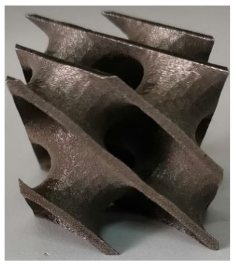
Figure 1.
D structure specimen.
2.2. Compression and Tensile Experiments
The quasi-static compression experiment of the D structure was carried out with a universal electronic tester. The speed of the indenter was 3 mm/min. The experiment ended when the load dropped rapidly to zero. The compressive stress–strain curve is shown in Figure 2. The compressive strength of the D structure was 667 MPa.
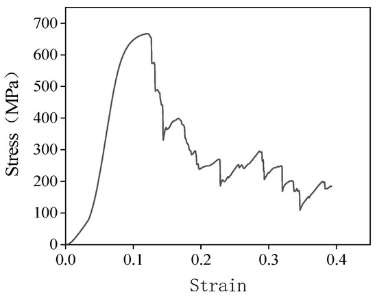
Figure 2.
Compression stress–strain curve of the D structure.
The tensile specimens were prepared with the same printing process parameters as the D structure, and the elastic modulus and tensile mechanical properties of the specimen were obtained. The shape and size of the tensile specimen are shown in Figure 3. The tensile mechanical properties of the bulk material are listed in Table 2.
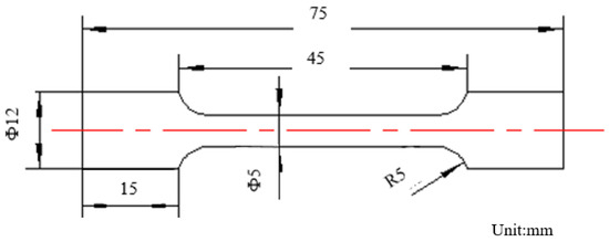
Figure 3.
Shape and size of tensile specimen.
Table 2.
Tensile mechanical properties of bulk material.
2.3. Microstructure Observation
In order to consider the influence of internal defects on the simulation results, the metallographic morphology of the SLM-deposited D structure was observed. As can be seen from Figure 4, only a small number of void defects can be observed in the D structure under the current group printing parameters. The voids are circled in Figure 4. The void fraction was used to characterize the number of void defects. The void fraction is defined as the ratio of the total void area to the metallographic observation area. Under the current set of print parameters, the voidage of the D structure was 0.037%.
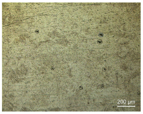
Figure 4.
Microstructure of the D structure deposited by SLM.
3. Simulation
The mechanical properties of the titanium alloy D structure were simulated by Abaqus software. The D structure was modeled by 3D design software, and the exported STL file was imported into Abaqus software to conduct a finite element analysis of the structure.
3.1. Finite Element Model
As shown in Figure 5, the indenter and base were set as discrete rigid bodies during the compression simulation. The reference points RP1 and RP2 were set on two rigid surfaces and assembled on the upper and lower surfaces of the D structure by the point coincidence constraint. The base was set to be fully fixed, and the speed of the indenter was 3 mm/min. Discrete rigid element R3D4 was used for mesh division. The interaction type of the D structure was set to self-contact, and the contact property was set to hard contact. The D structure meshed with the shell element S4R. A total of 4832 elements and 14,496 nodes were used for the D structure. An applied mesh size of 0.5 mm was verified by extensive simulation tests. Satisfactory simulation results could be obtained with the current mesh size of the element. In the material attribute, the elastic modulus and the yield strength of the Ti-6Al-4V alloy were set to 106 GPa and 1066 MPa, respectively.
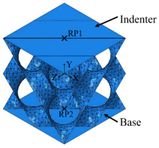
Figure 5.
Assembly diagram of the D structure and rigid surface.
The simulation result of D structure compressive strength was 646 MPa, close to the experimental result. The method can be used to study the effect of structural parameters on the mechanical properties of the D structure.
3.2. Simulation Results Considering Void Defects
The effect of void defects on the mechanical properties of the D structure was studied. Considering the effect of void defects and the amount of calculation, the cell size of the D structure was selected as 1.5 mm, the surface thickness was selected as 0.1 mm, and the void ratio was selected as 0.037%. The volume of the selected D structure was 0.66 . The average radius of a single void was 15 . According to the void ratio of 0.037%, there were about 16 voids in the selected D structure. Sixteen void defects were randomly arranged in the D structure, as shown in Figure 6. The voids were set to a highly soft material. The elastic modulus of the voids was set as 1MPa, and Poisson’s ratio was set as 0.001. The other simulation settings are the same as in Section 3.1.
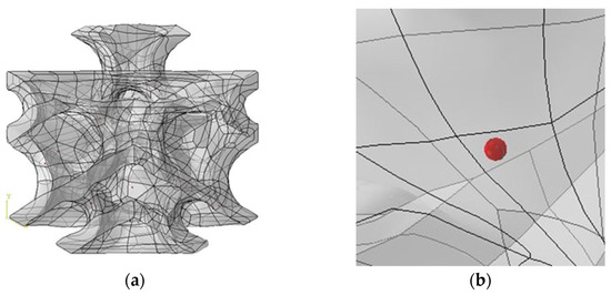
Figure 6.
D structure diagram considering voids of (a) finite element model and (b) enlarged view of a local area with voids.
The results of quasi-static compression with and without void defects are shown in Figure 7. There is no significant difference in the maximum von Mises stress of the D structure when no defects and void defects are taken into account. The compressive strengths of the D structure with and without void defects are 517 MPa and 520 MPa, respectively. By extracting the reaction force at the indenter, the maximum load forces of the D structure considering a void and without a void are 325 N and 327 N, respectively. Under the current print parameter, the low porosity compressive strength of structure D has almost no significant change [24]. The effect of void defects can be ignored during a simulation.
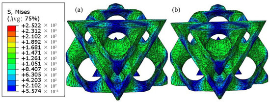
Figure 7.
Quasi-static compression simulation results of the D structure: (a) stress distribution without considering void defects, (b) stress distribution considering void defects.
4. The Influence of Structural Parameters
The mechanical properties of the D structure are directly affected by its structural parameters, such as surface thickness, cell size, and other structural factors. The mechanical properties of the D structure based on structural parameters are studied by simulation method.
4.1. Parameter Setting of the D structure
The basic structural parameters of the TPMS structure are surface thickness, unit cell size, and the number of unit cells. The influence of surface thickness and cell size on the mechanical properties of the D structure is studied.
In order to evaluate the compression performance of the D structure, six surface thicknesses and seven cell sizes of the D structure were selected for the uniaxial compression simulation analysis, as described in Section 2.2. The detailed parameter settings can be seen in Table 3. According to the GA model, by extracting the nominal compressive modulus and strength of the stress–strain curve at each relative density, the prediction formulas of the mechanical properties of the D structure are obtained. The nominal compressive modulus and strength are determined by the slope of the linear elastic portion of the stress–strain curve and the maximum strength during the entire loading process, respectively.
Table 3.
Structure parameters of the D structure.
4.2. GA Fitting Formulas of the D Structure
With the relative density as the horizontal coordinate and the nominal compressive modulus or strength as the vertical coordinate, the power function was used to fit the simulation data of the D structure. The GA fitting curves of the D structure are plotted, as shown in Figure 8.
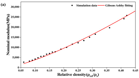
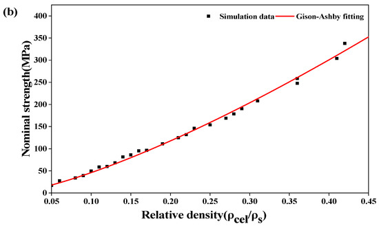
Figure 8.
Variations in (a) nominal modulus and (b) nominal maximum strength of the D structure with relative density.
The GA fitting formulas of the D structure are as follows:
As seen in Figure 8, the nominal modulus and strength of the D structure increase with the increase in relative density [25]. The correlation coefficients of the relative density-nominal compressive modulus and the relative density-nominal compressive strength are 0.993 and 0.996, respectively. The nominal compressive modulus and strength of the D structure can be predicted by the GA model. Moreover, when the product of the length and width of the unit cell is used as the cross-sectional area for the stress calculation, the greater the relative density, the more significant the change in mechanical properties.
4.3. The Modification of GA Fitting Formulas
In a lightweight design, the nominal modulus and strength will be underestimated when the cross-sectional area of a solid structure is used to calculate the D structure’s stress. The concept of an equivalent cross-sectional area is used to modify GA fitting formulas.
The equivalent cross-sectional area is as follows:
where is the volume of the porous structure, is the cell size of the porous structure along loading direction, and is the equivalent cross-sectional area.
The concept of an equivalent cross-sectional area is used to calculate the equivalent nominal modulus and strength of the D structure. The curves of the relative density-equivalent nominal modulus and the relative density-equivalent nominal strength are shown in Figure 9.
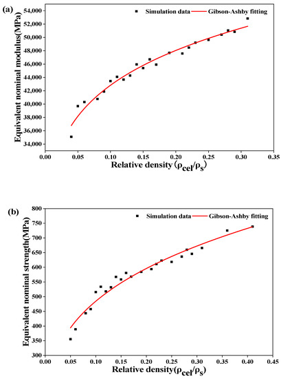
Figure 9.
Variations in (a) equivalent nominal modulus and (b) equivalent nominal strength of the D structure with relative density.
The modified GA fitting formulas of the D structure:
where is the equivalent nominal modulus and is the equivalent nominal strength.
As can be seen from Figure 9, the correlation coefficients of the relative density-equivalent nominal compressive modulus and the relative density-equivalent nominal compressive strength are 0.972 and 0.961, respectively. The compression modulus and strength of the D structure can be predicted by the modified GA fitting formulas. The equivalent nominal modulus and strength values calculated by the equivalent cross-sectional area are slightly larger. Moreover, when the equivalent cross-sectional area is used as the cross-sectional area for stress calculation, the greater the relative density, the smaller the change in mechanical properties. In a practical production, it is important to determine the relative density of the filling structure.
4.4. Prediction Formulas of Mechanical Properties Based on Structural Parameters
The influence of relative density on the mechanical properties of porous structures has been studied theoretically. However, to effectively utilize porous structures, other parameters, such as cell size, should be considered [23]. In this part, the prediction formulas of mechanical properties based on structural parameters are obtained by combining the structural parameters of the D structure with its relative density.
Prediction Formulas
The volume of TPMS structures is proportional to the surface area A and surface thickness t when the relative density is low [5]. The relative density can be expressed as follows:
where A is the surface area of the porous structure and t is the surface thickness of the porous structure.
The following results can be obtained by fitting the cell size and surface area of the D structure. As can be seen from Figure 10, the correlation coefficient between the cell size and surface area of the D structure is 1. The relationship between cell size and surface area of the D structure can be described by Formula (9).
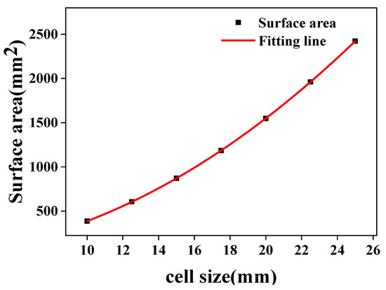
Figure 10.
Relationship of cell size and surface area of the D structure.
Substituting Equations (8) and (9) into Equations (1) and (2), the following results can be obtained.
where , , p, and q are material and structure constants.
The relative densities of porous structures used in the literature mainly range from 0.1 to 0.3 [26]. Therefore, the data with a relative density of less than 0.3 are selected for calculating the constants in Equations (10) and (11). Two groups of cell data with a cell size of 10 mm and surface thickness of 0.25 mm and 0.5 mm are substituted into Equations (10) and (11). The material and structure constants of , , p, and q are 0.735, 1.424, 0.179, and 0.321, respectively.
Equivalent nominal modulus of the D structure is as follows:
The equivalent nominal strength of the D structure is as follows:
It can be seen from Equations (12) and (13) that the equivalent compressive nominal modulus and strength increase as a power function when the cell size decreases or surface thickness increases [23].
The unit cell size and surface thickness data of 2–7 groups are inserted into Equations (12) and (13) to predict and verify their correctness. The verification results show that the errors of relative equivalent nominal modulus and strength are within 5% and 10%, respectively.
Based on the simulation results of the seven groups of D structures, the effects of structural parameters on mechanical properties are systematically studied. It can be seen from Figure 11 that the equivalent nominal strength and modulus of the D structure decrease with an increase in cell size or a decrease in surface thickness [20,23]. The influence of surface thickness on the equivalent nominal strength and modulus of the D structure gradually decreases with an increase in cell size, and the influence of cell size on the equivalent nominal strength and modulus of the D structure gradually decreases with an increase in surface thickness. The mass of the cell increases or decreases with the change in surface thickness and cell size.
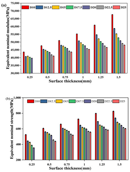
Figure 11.
Variations in (a) equivalent nominal modulus and (b) equivalent nominal maximum strength of the D structure with structural parameters.
5. Structural Lightweight Design Based on D Structure Filling
An example illustrates the practical application of the above formula for predicting mechanical properties based on structural parameters. The assembly block is a part of a rocket motor, as shown in Figure 12. To better apply this part, the structural lightweight design of the assembly block was carried out based on D structure filling technology.
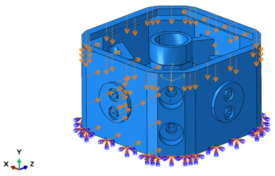
Figure 12.
Structure diagram of the assembly block.
5.1. Density Optimization of the Assembly Block
The mass of the assembly block was designed to be reduced by 20%. Based on the strength and stiffness, the structure of the assembly block was optimized. By optimizing the density of the assembly block, the relative density of the appropriate porous structure was determined, and the modulus and strength of the assembly block were optimized.
The schematic diagram of the assembly block filled with D cells is shown in Figure 12. Quadratic tetrahedral elements of type C3D10 were used for numerical analysis. A total of 106,647 elements and 168,775 nodes were used for the assembly block. The current mesh size of 3.06mm yielded a satisfactory simulation result. The material properties were set in the same way as the D structure material above. The assembly block was fixed at the bottom, and 15 KN forces were applied perpendicularly to two external surfaces along the X direction. A force of 12 KN was applied perpendicularly to the upper surface of the assembly block. With stiffness and strength as design objectives, the optimal density distribution of the assembly block was obtained.
As shown in Figure 13, the relative density of the loading side of the assembly block was mostly less than 0.3, while the others were less than 0.5. Considering that the D structure was filled in the interior of the assembly block with a 1 mm skin outside, the loading side could be filled with the D structure with a relative density of 0.3. Similarly, the non-loading side could also be filled with the D structure with a relative density of 0.2.
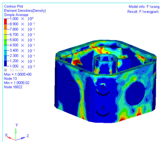
Figure 13.
Density optimization analysis result of the assembly block.
According to the characteristics of the filled part, the unit cell size of the D structure was selected as 15 mm. When the relative density was 0.3, the relative equivalent nominal modulus and strength were as follows:
Combined with Equations (12) and (13), the cell surface thickness was determined to be 1.69 or 1.25 mm. Similarly, when the relative density was 0.2, the cell surface thickness was determined to be 0.79 mm or 0.75mm.
When the cell size was 15 mm, and the surface thickness of the loading and non-loading sides were 1.25 mm and 0.75 mm, respectively, and the weight of the assembly block was reduced by 22%.
5.2. Stress Analysis of the Assembly Block
Due to the complexity of the D structure, it was time-consuming to use the D structure assembly block for a simulation analysis directly. Therefore, according to the principle that a solid block and a porous structure have the same compressive properties, the homogenization analysis method was used to analyze the assembly block filled with the D structure. The compressive modulus and strength extracted from the compressive stress–strain curve of the porous structure were assigned to the material attribute of the solid block. The homogenization results of the D structure are shown in Table 4. Cell 1a and cell 1b represent cells with different surface thicknesses.
Table 4.
Parameters and theoretical properties of unit cell.
The quadratic tetrahedral elements of type C3D10 were used in the numerical homogenization analysis. A total of 109,642 elements and 186,420 nodes were used for the homogenization assembly block. The current mesh size of 3.1mm yielded a satisfactory simulation result. The material properties were set in the same way as the D structure material above. The filling diagram of the assembly block after adjusting for a lightweight design is shown in Figure 14, where different colors represent D structures with different structural parameters.
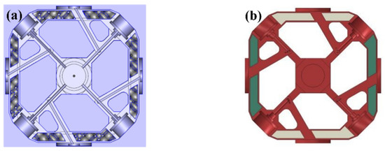
Figure 14.
Schematic diagram of the lightweight assembly block: (a) schematic diagram based on D structure filling, (b) homogenization diagram of the lightweight assembly block.
The force analysis of the assembly block before and after adjusting for a lightweight design was carried out with Abaqus software. The results are shown in Figure 15 and Figure 16.
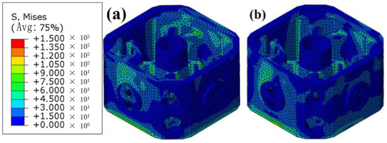
Figure 15.
Strength analysis results of (a) original assembly block and (b) lightweight assembly block based on D structure filling.
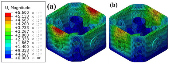
Figure 16.
Deformation analysis results of (a) original assembly block and (b) target lightweight part based on D structure filling.
It can be seen from Figure 15 and Figure 16 that the maximum von Mises stress of the assembly block is located at the internal connecting slabs for the original assembly block, and the maximum displacement is at the surface of the two loading sides. There are still large stress areas in the internal connecting slabs of the target lightweight part. However, compared with the original assembly block, the maximum von Mises stress did not change significantly. A larger deformation area still appeared on the surface of the two loading sides, but the deformation decreased to 0.044 mm after the lightweight design. Compared with the deformation of the original assembly block by 0.055 mm, the stiffness of the lightweight assembly block improved by nearly 20%.
6. Conclusions
(1) The mechanical properties of the Ti-6Al-4V alloy D structure were studied by means of simulations and experiments. The porosity of the TC4 samples deposited by SLM was 0.037%. The equivalent compressive nominal strengths of the D structure with and without void defects were similar. The effect of the defects was negligible in the subsequent studies.
(2) Using the concept of an equivalent cross-sectional area, the GA fitting formulas of the D structure were modified. The mechanical property prediction formulas based on structural parameters were obtained by connecting the structural parameters of the D structure with its relative density.
(3) The D structure showed a cubic relationship between the surface area and the cell size. The formulas for predicting the compressive strength and modulus of the D structure by cell size and thickness were derived. The equivalent compressive nominal strength and modulus of the D structure increased with an increase in surface thickness and a decrease in cell size.
(4) According to the prediction formula of the compressive strength and modulus of the D structure, the lightweight design of the assembly block was achieved by the D structure. When the weight of the assembly block was reduced by 22%, the maximum von Mises stress of the structure through a lightweight design did not change significantly, and the stiffness was improved by 20%. A lightweight structure design based on D structure filling technology can therefore meet the design requirements.
Author Contributions
Data curation, X.C.; Formal analysis, X.C.; Funding acquisition, Z.D.; Investigation, W.K.; Methodology, G.S.; Project administration, W.K.; Supervision, G.S., D.S. and Z.D.; Validation, J.Z.; Visualization, J.Z.; Writing—original draft, X.C.; Writing—review and editing, G.S. All authors have read and agreed to the published version of the manuscript.
Funding
This research was funded by [National Natural Science Foundation of China] grant number [92160205, 11672010].
Institutional Review Board Statement
Not applicable.
Informed Consent Statement
Not applicable.
Data Availability Statement
Data included in this study are available upon request by contact with the corresponding author.
Acknowledgments
This work is financially supported by the National Natural Science Foundation of China (Grant No. 92160205, 11672010).
Conflicts of Interest
The authors declare no conflict of interest.
Nomenclature
| Elastic modulus of the porous structure | |
| Modulus of the material constituting the porous structure | |
| Density of the porous structure | |
| Density of the material constituting the porous structure | |
| Compress stress of the porous structure | |
| Compress stress of the material constituting the porous structure | |
| Equivalent cross-sectional area of the porous structure | |
| Volume of the porous structure | |
| Cell size of porous structure along loading direction | |
| Equivalent nominal modulus of the porous structure | |
| Equivalent nominal strength of the porous structure | |
| The surface area of the porous structure | |
| The surface thickness of the porous structure | |
| Material and structure constant | |
| Material and structure constant | |
| Material and structure constant | |
| Material and structure constant | |
| Material and structure constant | |
| Material and structure constant | |
| Material and structure constant | |
| Material and structure constant |
References
- Bartolomeu, F.; Gasik, M.; Silva, F.S.; Miranda, G. Mechanical Properties of Ti6Al4V Fabricated by Laser Powder Bed Fusion: A Review Focused on the Processing and Microstructural Parameters Influence on the Final Properties. Metals 2022, 12, 986. [Google Scholar] [CrossRef]
- Atwater, M.A.; Guevara, L.N.; Darling, K.A.; Tschopp, M.A. Solid State Porous Metal Production: A Review of the Capabilities, Characteristics, and Challenges. Adv. Eng. Mater. 2018, 20, 1700766. [Google Scholar] [CrossRef]
- Günther, F.; Hirsch, F.; Pilz, S.; Wagner, M.; Gebert, A.; Kästner, M.; Zimmermann, M. Structure-property relationships of imperfect additively manufactured lattices based on triply periodic minimal surfaces. Mater. Des. 2022, 222, 111036. [Google Scholar] [CrossRef]
- Xiao, X.; Xie, L.; Tang, R.; Liu, J.; Song, P.; Zhu, X.; Zhao, J.; Jiang, C.; Yang, S.; Wu, P. Improved Compressive Properties of Lattice Structure Based on an Implicit Surface Hybrid Optimization Design Method via Selective Laser Melting. Metals 2022, 12, 1477. [Google Scholar] [CrossRef]
- Zhang, L.; Feih, S.; Daynes, S.; Chang, S.; Wang, M.Y.; Wei, J.; Lu, W.F. Energy absorption characteristics of metallic triply periodic minimal surface sheet structures under compressive loading. Addit. Manuf. 2018, 23, 505–515. [Google Scholar] [CrossRef]
- Liu, B.; Liu, M.; Cheng, H.; Cao, W.; Lu, P. A new stress-driven composite porous structure design method based on triply periodic minimal surfaces. Thin-Walled Struct. 2022, 181, 109974. [Google Scholar] [CrossRef]
- Yang, L.; Ferrucci, M.; Mertens, R.; Dewulf, W.; Yan, C.; Shi, Y.; Yang, S. An investigation into the effect of gradients on the manufacturing fidelity of triply periodic minimal surface structures with graded density fabricated by selective laser melting. J. Mater. Process. Technol. 2020, 275, 116367. [Google Scholar] [CrossRef]
- Soro, N.; Attar, H.; Wu, X.; Dargusch, M.S. Investigation of the structure and mechanical properties of additively manufactured Ti-6Al-4V biomedical scaffolds designed with a Schwartz primitive unit-cell. Mater. Sci. Eng. A 2019, 745, 195–202. [Google Scholar] [CrossRef]
- Afshar, M.; Anaraki, A.P.; Montazerian, H.; Kadkhodapour, J. Additive manufacturing and mechanical characterization of graded porosity scaffolds designed based on triply periodic minimal surface architectures. J. Mech. Behav. Biomed. Mater. 2016, 62, 481–494. [Google Scholar] [CrossRef]
- Wang, H.; Chen, P.; Wu, H.; Chen, A.; Wu, S.; Su, J.; Wang, M.; Feng, X.; Yang, C.; Yang, L.; et al. Comparative evaluation of printability and compression properties of poly-ether-ether-ketone triply periodic minimal surface scaffolds fabricated by laser powder bed fusion. Addit. Manuf. 2022, 57, 102961. [Google Scholar] [CrossRef]
- Abueidda, D.W.; Abu Al-Rub, R.K.; Dalaq, A.S.; Lee, D.-W.; Khan, K.A.; Jasiuk, I. Effective conductivities and elastic moduli of novel foams with triply periodic minimal surfaces. Mech. Mater. 2016, 95, 102–115. [Google Scholar] [CrossRef]
- Kadkhodapour, J.; Montazerian, H.; Raeisi, S. Investigating internal architecture effect in plastic deformation and failure for TPMS-based scaffolds using simulation methods and experimental procedure. Mater. Sci. Eng. C 2014, 43, 587–597. [Google Scholar] [CrossRef] [PubMed]
- Ambu, R.; Morabito, A.E. Porous Scaffold Design Based on Minimal Surfaces: Development and Assessment of Variable Architectures. Symmetry 2018, 10, 361. [Google Scholar] [CrossRef]
- Elenskaya, N.; Tashkinov, M. Modeling of Deformation Behavior of Gyroid and I-WP Polymer Lattice Structures with a Porosity Gradient. Procedia Struct. Integr. 2021, 32, 253–260. [Google Scholar] [CrossRef]
- Kladovasilakis, N.; Tsongas, K.; Kostavelis, I.; Tzovaras, D.; Tzetzis, D. Effective mechanical properties of additive manufactured triply periodic minimal surfaces: Experimental and finite element study. Int. J. Adv. Manuf. Technol. 2022, 121, 7169–7189. [Google Scholar] [CrossRef]
- Gibson, I.J.; Ashby, M.F. The mechanics of three-dimensional cellular materials. Proc. R. Soc. London. A. Math. Phys. 1982, 382, 43–59. [Google Scholar]
- Gibson, L.J.; Ashby, M.F. Cellular Solids: Structure and Properties; Cambridge University Press: Cambridge, UK, 1997. [Google Scholar]
- Lu, Y.; Zhao, W.; Cui, Z.; Zhu, H.; Wu, C. The anisotropic elastic behavior of the widely-used triply-periodic minimal surface based scaffolds. J. Mech. Behav. Biomed. Mater. 2019, 99, 56–65. [Google Scholar] [CrossRef]
- Maskery, I.; Sturm, L.; Aremu, A.O.; Panesar, A.; Williams, C.B.; Tuck, C.J.; Wildman, R.D.; Ashcroft, I.; Hague, R.J.M. Insights into the mechanical properties of several triply periodic minimal surface lattice structures made by polymer additive manufacturing. Polymer 2018, 152, 62–71. [Google Scholar] [CrossRef]
- Abueidda, D.W.; Bakir, M.; Al-Rub, R.K.A.; Bergström, J.S.; Sobh, N.A.; Jasiuk, I. Mechanical properties of 3D printed polymeric cellular materials with triply periodic minimal surface architectures. Mater. Des. 2017, 122, 255–267. [Google Scholar] [CrossRef]
- Yang, L.; Han, C.; Wu, H.; Hao, L.; Wei, Q.; Yan, C.; Shi, Y. Insights into unit cell size effect on mechanical responses and energy absorption capability of titanium graded porous structures manufactured by laser powder bed fusion. J. Mech. Behav. Biomed. Mater. 2020, 109, 103843. [Google Scholar] [CrossRef]
- Yang, E.; Leary, M.; Lozanovski, B.; Downing, D.; Mazur, M.; Sarker, A.; Khorasani, A.; Jones, A.; Maconachie, T.; Bateman, S.; et al. Effect of geometry on the mechanical properties of Ti-6Al-4V Gyroid structures fabricated via SLM: A numerical study. Mater. Des. 2019, 184, 108165. [Google Scholar] [CrossRef]
- Maskery, I.; Aremu, A.O.; Simonelli, M.; Tuck, C.; Wildman, R.; Ashcroft, I.; Hague, R. Mechanical Properties of Ti-6Al-4V Selectively Laser Melted Parts with Body-Centred-Cubic Lattices of Varying cell size. Exp. Mech. 2015, 55, 1261–1272. [Google Scholar] [CrossRef]
- Sienkiewicz, J.; Płatek, P.; Jiang, F.; Sun, X.; Rusinek, A. Investigations on the Mechanical Response of Gradient Lattice Structures Manufactured via SLM. Metals 2020, 10, 213. [Google Scholar] [CrossRef]
- Keshavarzan, M.; Kadkhodaei, M.; Badrossamay, M.; Ravari, M.K. Investigation on the failure mechanism of triply periodic minimal surface cellular structures fabricated by Vat photopolymerization additive manufacturing under compressive loadings. Mech. Mater. 2020, 140, 103150. [Google Scholar] [CrossRef]
- Refai, K.; Brugger, C.; Montemurro, M.; Saintier, N. An experimental and numerical study of the high cycle multiaxial fatigue strength of titanium lattice structures produced by Selective Laser Melting (SLM). Int. J. Fatigue 2020, 138, 105623. [Google Scholar] [CrossRef]


Disclaimer/Publisher’s Note: The statements, opinions and data contained in all publications are solely those of the individual author(s) and contributor(s) and not of MDPI and/or the editor(s). MDPI and/or the editor(s) disclaim responsibility for any injury to people or property resulting from any ideas, methods, instructions or products referred to in the content. |
© 2023 by the authors. Licensee MDPI, Basel, Switzerland. This article is an open access article distributed under the terms and conditions of the Creative Commons Attribution (CC BY) license (https://creativecommons.org/licenses/by/4.0/).